三相感应电动机设计软件 EXCER版 25HP6P GB3 536(2012版标准 180L)
三相能耗计 Telstar CT 快速启动指南说明书
3-Phasen EnergiezählerTelstar CTQuick Starter GuideInstallationBevor Sie Ihr smart-me Gerät verwenden können, müssen Sie es mit Ihrem Wi-Fi Netzwerk verbinden.1.Verbinden Sie Ihr Smartphone oder Tablet mit dem WLAN.2.Downloaden und installieren Sie die kostenlose smart-me App.3.Starten Sie die App und erstellen Sie einen kostenlosen Account4.Klicken Sie auf …Gerät hinzufügen“ (+) und folgen Sie den Anweisungen.Quick StartGera t e U b ersichtOben links finden Sie die Geräteübersicht. Um die Gruppierung IhrerGeräte zu ändern, besuchen Sie das smart-me Webportal.Zahler DetailsFurdie Detailansicht eines Zahlers klicken Sie oben links auf das Menuund wah len den entsprechenden Zahler aus.Ereignis-Aktionen und WENN / DANN AktionenUm Ereignis Aktionen zu konfigurieren, gehen Sie auf und wa h len Sie «Editieren». Klicken Sie danach auf «Interne Ereignis-Aktionen».WENN/DANN Aktionen können Sie im Webportal konfigurieren.Beispiel:WENN Leistung grösser als 100 Watt DANN sende einen Alarm (E-Mail).Ausgänge S0-0 & S-1Gehen Sie auf und wa h len Sie «Editieren».Klicken Sie dann auf «Ausga n ge undEinga n ge». Hier ko n nen beide Ausga n ge konfiguriert werden.Art des Ausgangs 0Die Art des Ausgangs 0kann auch auf «Digitaler Ausgang» gestellt werden. Sobald dies gespeichert wird, ist ein zusa t zlicher Schalter in der Geräteübersicht sichtbar. (Achtung max.Schaltleistung <0.4W)Einstellungen digitaler Eingang / TarifumschaltungUm von der Tarifumschaltung auf den digitalen Eingang zu wechseln,gehen Sie auf und wa h len «Editieren» . Klicken Sie danach auf «Ausga n ge und Einga n ge». Hier kann der digitale Eingang / Tarif Eingang konfiguriert werden. Sobald diese Einstellung gespeichert wird, ist eine zusa t zliche Kachel sichtbar.Allgemeine EinstellungenUm die allgemeinen Einstellungen zu konfigurieren, gehen Sie auf und wa h len «Editieren». Klicken Sie danach auf «Allgemeine Einstellungen».Blindenergie:Soll diese in der App und dem Web Interfacedargestellt werden, kann dies hier aktiviert werden (nur mo g lich mit Professional Abo).Einstellung WandlerfaktorGehen Sie aufund wa h len Sie «Editieren». Klicken Sie dann auf “Allgemeine Einstellungen”. Wählen Sie nun den Wandlerfaktor gemäss den eingesetzten Stromwandlern.Sie können das Wandlerverhältnis sperren. Danach kann der Faktor nicht mehr geändert werden bis eine Neuinstallation des Zählers durchgeführt wird.DisplayAktiver Tarif 1 oder Tarif 2Stromrichtung (rechts Bezug / links Lieferung)WiFi/LTE Signalsta r keMomentan gemessene Leistung mit EinheitOBIS Kennzahl für den angezeigten Zählerstand ZählerstandEinheit des angezeigten ZählerstandesDisplayanzeige AblaufDer Za h ler hat ein rollendes Display.Die unten beschriebenen Punkte werden nacheinander angezeigt und wiederholt.1)Za h lerstand (OBIS Code gefolgt von Za h lerstand)1.8.1(A+) Wirkenergie Bezug Tarif 11.8.2(A+) Wirkenergie Bezug Tarif 22.8.1(A-) Wirkenergie Lieferung Tarif 12.8.2(A-) Wirkenergie Lieferung Tarif 21.8.0:5A (A+) Wirkenergie Total Bezug 5A Basis 2.8.0:5A (A-) Wirkenergie Total Lieferung 5A Basis 5.8.0(Q1) Induktive Blindenergie Bezug total 6.8.0(Q2) Kapazitive Blindenergie Bezug total 7.8.0(Q3) Induktive Blindenergie Lieferung total 8.8.0(Q4) Kapazitive Blindenergie Lieferung total2)Wandlerfaktor (OBIS Code gefolgt von Informationen)0.4.2 Wandlerfaktor (inkl. S0 Impulse / kWh)3)Firmware (OBIS Code gefolgt von Informationen)C.1.6Ch: 2218Firmware Checksumme 0.2.0V 1.1Firmware Version4)Fehleranzeige (OBIS Code gefolgt von Fehlermeldungen)C.60.9Fraud Flag (möglicher Betrugsversuch erkannt)PhL: 1nur Phase L1 angeschlossen PhL: 2nur Phase L2 angeschlossen PhL: 3nur Phase L3 angeschlossen PhL: 23Phase L1 nicht angeschlossen PhL: 13Phase L2 nicht angeschlossen PhL: 12Phase L3 nicht angeschlossenKorrekte Phasenreihenfolge:Zahlen leuchten statisch Falsche Phasenreihenfolge:Zahlen blinkenTechnische DatenBetriebsspannung3 x 230/400 VAC Strombereich I min -I ref (I max)0.01-1(6)AGenauigkeitsklasse B (1%)Betriebstemperatur −25 bis +70 °C Lagertemperatur −40 bis +85 °C LuftfeuchtigkeitJahresmittel 75%,kurzzeitig 95%,nicht kondensierendProdukt Zertifizierung CE, MID 2014/32/EU, RED Messgeräte Kategorie CAT IIISchutzart Klemmen: IP20Gehäuse: IP51Umweltklassen Mechanisch: M1Elektrisch: E2Zählerart4-Quadrantenzähler(Wirk-und Blindenergie,Bezug und Lieferung)Impulsausgang S0-0Opto Power MOSFET, P MAX = 0.4 W 12 - 48VDC / 12 - 230 VACImpulswertigkeit S0-01’000 oder 10’000 Impulse/kWh Leistungsausgang S-1Relais, P MAX = 1’500 Wmax. 48VDC / max. 230 VAC Tarifeingang E112 - 48VDC / 12 - 230 VACTechnische Irrtümer und Änderungen vorbehaltenSicherheitshinweiseDie Sicherheitshinweise sind unter allen Umsta n den einzuhalten:●Das Gera t ist fu r die Verwendung in Geba u den vorgesehen.●Das Gera t ist fu r den Betrieb an einem trockenen, staubfreien Ort ohne direkte Sonneneinstrahlung vorgesehen.●Ha u figes An- und Ausschalten kann die Lebensdauer elektrischer Gera t e verku r zen. Richten Sie nur dann eine automatische Schaltung mit ha u figen An- und Ausschaltvorga n gen ein, wenn dieangeschlossenen Gera t e dafu r ausgelegt sind. Fu r entsprechende Scha d en an angeschlossenen Gera t en wird nicht gehaftet.●Bei der Installation oder beim Wechseln des Gera t es mu s sen die Leiter, die an das Gera t angeschlossen werden, spannungsfrei sein.●Das Beru h ren unter Spannung stehender Teile ist lebensgefa h rlich!Deshalb sind die entsprechenden Vorsicherungen zu entfernen und so aufzubewahren, dass andere Personen diese nicht unbemerkt wiedereinsetzen ko n nen.●Die Installation des Gera t es darf nur von fachkundigem und entsprechend geschultem Personal erfolgen.●Die ortsu b lichen Sicherheits- und Werkvorschriften sind einzuhalten.●Der Energiezähler muss in einem Schrank mit der Schutzart IP51 oder besser installiert werden●Isolierung der Netzanschlussklemmen: Verstärkt ●Isolierung von S1, S0-0 und E1 Klemmenanschlüsse:Wenn eine Klemme mit Spannungen über SELV verwendet wird, ist eine verstärkte Isolierung für alle Klemmen erforderlich.AnschlussschemaT1Taste für die InstallationT2SpezialfunktionenKurz : Wird T2 >2s gedrückt, schaltet die grüne LED-Lampe ein / aus. Wenn diese aktiviert ist, zeigt diese den Verbindungszustand anGrün leuchtend: verbunden mit smart-me CloudGrün blinkend: Verbindungsaufbau oder keine Verbindung Lang : Wird T2 >8s gedrückt, wird die Anzeige der Leistung zwischen Wirk- & Blindleistung umgeschaltet. Ausserdem wechselt die Eichimpuls-LED zwischen Wirkenergie und Blindenergie.Sehr lang : Wird T2 >14s gedrückt, wird der S0-0Impulsausgang zwischen Wirkleistung und Blindleistung umgeschaltet.ACHTUNG:Diese Einstellung ändert nur die Anzeige auf dem Display,nicht in der smart-me Cloud (App und Webseite).Soll die Blindenergie in der Cloud angezeigt werden,muss dies in den allgemeinen Einstellungen gemacht werden.E1Tarifeingang, potentialfreiTarif 1:0V (oder nicht angeschlossen)Tarif 2:12 -48VDC / 12 - 230VAC einstellbar als digitaler EingangS0-0S0 Impulsausgang, potentialfreiPower MOSFET mit P MAX = 0.4 W einstellbar als digitaler AusgangS-1Leistungsausgang, potentialfreiRelais mit P MAX = 1’500 WQUICK INSTALLATION GUIDE3-Phasen EnergiezählerTelstar CTDEUTSCH23.07.2021LETTENSTRASSE 9 | 6343 ROTKREUZ | SWITZERLAND********************|+41(0)415110970Bei generellen Fragen sind weitere Informationen auf unserer Webseite sowieauf der Wiki-Plattform zu finden:smart-me wiki:。
maxwell软件-三相感应电机
8三相感应电动机本章我们将简化RMxprt一些基本操作的介绍,以便介绍一些更高级的使用。
有关RMxprt基本操作的详细介绍请参考第一部分的章节。
8.1基本理论三相感应电机的定子绕组通常连接到对称的三相电源上。
定子绕组由p对极组成,在空间成正弦分布,定子电流产生旋转磁场。
转子绕组一般为鼠笼型,其极数与定子绕组保持一致。
转子导条中感应的电流反过来又产生一个旋转磁场,这两个旋转磁场在电机气隙中相互作用产生合成磁场。
气隙合成磁场与转子导条电流相互作用产生电磁转矩,使转子按磁场旋转的方向旋转,同时有一个大小相同方向相反的转矩反作用于定子上。
定子绕组分为p组线圈,每一组都按三相对称分布,在电机中占据n D/2P空间,此处D为气隙直径。
因而气隙磁场有p个周期,定子绕组具有p对极。
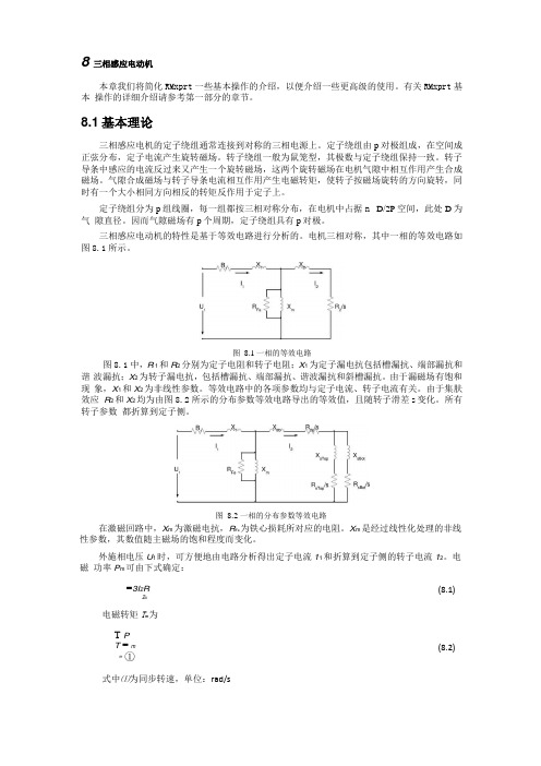
三相感应电动机的特性是基于等效电路进行分析的。
电机三相对称,其中一相的等效电路如图8.1所示。
图8.1中,R 1和R2分别为定子电阻和转子电阻;X1为定子漏电抗包括槽漏抗、端部漏抗和谐波漏抗;X2为转子漏电抗,包括槽漏抗、端部漏抗、谐波漏抗和斜槽漏抗。
由于漏磁场有饱和现象,X1和X2为非线性参数。
等效电路中的各项参数均与定子电流、转子电流有关。
由于集肤效应R2和X2均为由图8.2所示的分布参数等效电路导出的等效值,且随转子滑差s变化。
所有转子参数都折算到定子侧。
在激磁回路中,X m为激磁电抗,R Fe为铁心损耗所对应的电阻。
X m是经过线性化处理的非线性参数,其数值随主磁场的饱和程度而变化。
外施相电压U1时,可方便地由电路分析得出定子电流11和折算到定子侧的转子电流12。
电磁功率P m可由下式确定:=3I2R2s电磁转矩T m为T PT = mm①式中⑴为同步转速,单位:rad/s(8.1)(8.2)图8.1一相的等效电路图8.2 一相的分布参数等效电路轴端输出机械转矩为T2= T m - TW式中f 为风阻和摩擦转矩 输出功率为 P = T ①222式中巴=3(1-s )为转子转速,单位:rad/s 输入功率为P1= P2 +P加 +PCu2+PFe+九 +P(8.5)式中,尸彳风摩损耗,尸cu2为转子铜损耗,P Fe 为铁心损耗,P Cu1为定子铜损耗,P s 为杂散损耗。
Fluke 6003A三相电力校准器操作员手册说明书

6003AThree Phase Power Calibrator操作员手册July 2014(Simplified Chinese)© 2014 Fluke Corporation. All rights reserved. Specifications are subject to change without notice.All product names are trademarks of their respective companies.有限担保及责任范围Fluke 公司保证其每一个Fluke的产品在正常使用及维护情形下,其用料和做工都是毫无瑕疵的。
保证期限是一年并从产品寄运日起开始计算。
零件、产品修理及服务的保证期是 90 天。
本保证只提供给从 Fluke 授权经销商处购买的原购买者或最终用户,且不包括保险丝、电池以及因误用、改变、疏忽、或非正常情况下的使用或搬运而损坏(根据 Fluke 的意见而定)的产品。
Fluke 保证在 90 天之内,软件会根据其功能指标运行,同时软件已经正确地被记录在没有损坏的媒介上。
Fluke 不能保证其软件没有错误或者在运行时不会中断。
Fluke 仅授权经销商将本保证提供给购买新的、未曾使用过的产品的最终用户。
经销商无权以 Fluke 的名义来给予其它任何担保。
保修服务仅限于从 Fluke 授权销售处所购买的产品,或购买者已付出适当的Fluke国际价格。
在某一国家购买而需要在另一国家维修的产品,Fluke 保留向购买者征收维修/更换零件进口费用的权利。
Fluke 的保证是有限的,在保用期间退回 Fluke 授权服务中心的损坏产品,Fluke有权决定采用退款、免费维修或把产品更换的方式处理。
欲取得保证服务,请和您附近的Fluke服务中心联系,或把产品寄到最靠近您的Fluke服务中心(请说明故障所在,预付邮资和保险费用,并以 FOB 目的地方式寄送)。
UT267B智能三相数字相电功率表使用说明书

1TITLE PAGE Warnings 3I.Overview 6 II. Electrical Symbols 8III.Technical Specifications 9 1. Reference and Operating Conditions 9 2. General Specifications 11 3. General Differences and Performance Indexes under Reference Conditions 16IV. Structure of Meter 17V. Operating Instructions 18 1. Power On/Off 18 2. Backlight Control 18Contents23TITLE PAGE 3. Data Hold and Save 18 4. Data Access and Exit 19 5. Data Delete 19 6. Display Mode Switchover 20 7. Measurement 22 8. Data Transmission to Pc 29VI. Battery Replacement 29VII. Other Items and Notes 32VIII. Product Checklist35Thank you for purchasing our product UT267B intelligent three-phasedigital phase volt-ampere meter (also known as three-phase digital volt -ampere meter). In order to use the product properly, please follow instructions below:Please read user manual carefullyStrictly follow safety rules and notes mentioned in this manualWarnings4567I. OverviewUT267 intelligent three-phase digital phase volt-ampere meter (there-phase digital phase volt-ampere meter) comes out from hard efforts of our developers and is a fully automatic, multi-purpose, digital and intelligent meter specially designed for on-site measurement and with following features: high accuracy, high stability, low power consumption and easy operation. Without cutting off measured circuits, it can measure three-phase AC voltage and current, phase angles between voltages, currents or both, frequency, phase sequence, active, reactive and apparent power, power factor, sum of current vector; it is able to identify wiring groups of transformers, inductive and capacitive circuits as well as secondary circuits and bus differential protection system measurement; it also can read out differential protection phase between CT units, check and ensure correct wiring of kilowatt-hour meter, good conditions of wiring equipments, ect, which all together turn this kind of The meter, designed with latest materials for shell pattern and anti-vibration, anti-skidding, high-insulation protection jacket, can offer 240dots 160dots and dynamic display together with vector diagram indication, thus presenting users luxurious and elegant exterior structure. It is equipped with RS232 and available for data storage of 500 sets which transferred into PC through system software for further online real-time monitoring, history lookup, dynamic display, data readout, save, report and printing, ect.meter a safe, accurate and convenient new electric instrument offered for electric inspectors.This kind of meter is also known as three-phase digital phase volt-ampere meter, multi-purpose three-phase digital phase volt-ampere meter, automatic phase volt-ampere meter, tri-clamp digital phase volt-ampere meter, phase volt-ampere meter, three-phase electrical parameter tester. It can fully enjoy functions from intelligent dual-clamp phase volt-ampere meter and general machinery dual-clamp digital phase volt-ampere meter, which is applied inelectric power, petrochemical, metallurgy, railway, factories and mining, R&D institutes, metrological department. It is particularly needed in electric charging and relay protection system, electric power calculation, check and monitoring from power supply remarketing departments as well as electric installment, relay protection, differential inspection, start-up testing, power transformation check , electrical training, skill competition performed by technical department.II. Electrical SymbolsIII. Technical Specifications 1. Reference and Operating Conditions2. General Specifications101215* The meter flashes before automatically power off and continues to work with ON button pressed down.(15 minutes as a working period)163. General Differences and Performance Indexes under Reference Conditions. Notes1: Phase angle differences should be less than 3 under the working conditions, 6is for phase angle tolerance between 5mA 10mA IV. Structure of Meter1. USB-RS232 Interface2. Vibration-Proof Insulation Jacket3. LCD Display4. Functional Button Zone5. Three-Phase Voltage Input T erminals6. Current Input T erminal I37. Current Input T erminal I28. Current Input T erminal I19. Current Clamp Output Plug 10. Sharp Current Jaw11. V oltage Input T esting Cables4. Data Access and Exit Press MENU to enter into data access status during measurement, indicated by RD icon, then data lookup starts from R 001press Up button to increment by 1, Down button to decrement by 10 and Left to exit this status and return to measuring mode.5. Data Delete Press Right button when still under data access data to enter into data delete option, then Left or Right button to move the cursor to select YES or NO , next MENU button for confirmation or exit, finallyreturning to measuring mode. 1819V. Operating Instructions Note: Please carefully check if there are damaged parts or not before safe use. Do not use the meter on dangerous sites. Install the battery according to the manual. Do not simultaneously press 2 buttons or more in case of invalid operation.1. Power On/OffPress ON to power on and LCD displays. Press OFF button to power off, the meter will automatically power off 15 minutes later after power on.2. Backlight Controldark sites and at night.3. Data Hold and StoragePress HOLD button to maintain displayed data under measuring status, indicated by HD icon, press again to cancel the operation. The meter will automatically save and number current data while maintaining the data, indicated by group serial number such as S 001. Max 500 sets of data is available for the meter, displayed by FULL if the number is achieved.20216. Display Mode SwitchoverThe meter will automatically enter into voltage, current, phase display measuring modes (Figure A) after power on; then press Down button to go into display modes of active and reactive power, apparent power, power factor, frequency , three-phase current vector measurement (Figure B); orRight button to access phase sequence status (Figure C); Left button todisplay vector gram (Figure D); or Up button to back to voltage, current,phase measuring mode. Particularly to mention is that three-phase powerand power factor in figure B correspond to those of U1I1, U2I2, U3I3.23Voltage terminals U1, U2, U3 are named the same with red marks on current clamps.The Current clamping direction should accord with those of red marks during phase measuring This meter can measure three-phase voltage and current, phase angle between voltages, currents and both, frequency, active and reactive power , apparent power, power factor, three-phase sum of current vector, and also differentiate phase sequence, inductive and capacitive circuits, ect.Testing wire connection is shown as below:1. Single Phase Measuring: Connect measured voltage lines L, N to yellow U1 and black COM terminals, then current clamp I1 grasping L line. It also works by choosing Green U2, black COM, I2 or red U3, black COM and I3.24252. Three-Phase Four-Wire Measuring:Connect yellow UA, green UB, red UC and black N correspondingly to terminals yellow U1, green U2, red U3 and black COM on the meter, then get current clamps I1, I2, I3 grasp measured IA, IB, IC.3. Three-Phase Three-Wire Measuring:Connect measured voltage lines to yellow UA, red UC and Green UBcorrespondingly to terminals of the mete yellow U1, red U3 and black COM, then get current clamps I1, I3 grasp measured IA and IC. Reference connection figure shown as below.It is possible to differentiate among inductive and capacitive load, phase sequence and the polarity during measuring. If U1I1 phase angle is displayed ranging from 090, it measured load will be diagnosed as inductive; it is capacitive load with scope from 270360; it is positive phase sequence and has the same polarity with phase angles all close to120 ; otherwise positive phase sequence and reverse polarity is obtained with phase angle close to120and 300( it may caused by wrong current clamping or wiring connection), other conditions will be identified as reverse phase sequence (absence of phase not considered).Under phase sequence measuring mode, U1, U2, U3 or I1, I2, I3 are considered as positive phase sequence with cursor flashing from left to right side; and if the other way, U1, U2, U3 or I1, I2, I3 cursor move from right to left side. If corresponding cursor does not flash, it is likely that phase may be absent or signal amplitude is too low.2627Connection Figures shown as below:1. Single --Phase Voltage, Current, Phase Angle, Frequency , Power Measurement:2. Three-phase Four-Wire Voltage, Current, Phase Angle and Sequence, Frequency, Power and Power Factor Measurement:3. Three-Phase Three-Wire Voltage, Current, Phase Angle, Phase Sequence, Frequency, Power and Power Factor Measurement:8. Data Transmission to PCThe accessory RS232 connection line is used for communication of themeter with PC. With the meter power on and the software running, several following operations such as history lookup, data recall, save, report sheet, history printing can all be performed. The more data the meter saves,more time it will take to read out. History data can be saved in Txt or Excel format.VI. Battery ReplacementNote:Please ensure correct polarity when installing the battery, otherwise itcauses damage to the meterIt is prohibited to change batteries on dangerous sitesYou must use Qualified alkaline dry battery (1.5V AA6)New and old batteries are not allowed to combine for use282930311. Low battery icon will be displayed with power supply below 7.2V, please timely change batteries and do as below: 2. Press OFF button to power off. 3. Use cross-shaped screwdriver to loosen one bolt away from the battery cover and open it.4. Replace old batteries with new ones and ensure right polarity is selected.5. Close the battery cover and tighten the bolt.6. Press ON button to check if the battery is successfully replaced, if not, repeat operations from the second step.7. T ake the battery out if the mete is not in use for long time.Tight Loose Battery cover3233VII. Other Items and Notes:1. Exclusiveness of Current ClampsThere are three current clamps attached to every meter, which can not be exchanged for the other meters. Current clamps should be prevented from any crush and kept clean in order to ensure reliability when closing up to measure.2. Maintenance of Current ClampsPlease clean up clamp jaw surface after measurement, soft cloth coupled with lubricant (eg: WD-40 lubricant) instead of rough cloth or the corrosive are expected to use for the clearing. Please clean again just before use.3. The meter can be used to measure secondary circuits and low voltage loop, however, not suggested to measure current in high-voltage circuits in case of electric shock.4. Three-Phase Four-Wire (phase angle under three-phase load balance)5. Three-phase Three-Wire (phase angle under three-phase load balance):34356. Three-Phase Four-Wire and Three-Phase Three-Wire VectorgramsThree-Phase Four-Wire Vectorgram Three-Phase Three-Wire VectorgramIf current clamps or current wires are incorrectly attached, the displayed phase difference will be 180, that is to increment by 180 based onreference values above.Note:VIII. Product Checklist。
意法半导体电机控制参考指南说明书

电机控制3 意法半导体电机控制生态系统4 PMSM & BLDC电机8 3相感应电机(ACIM)12 步进电机14 直流有刷电机16 通用电机18 开关磁阻电机19 微控制器25 STM32电机控制生态系统29 电机驱动器IC39 电源模块44 功率MOSFET46 IGBT47 600-650 V IGBT系列48 1200 V IGBT系列49 二极管 & 整流器50 晶闸管、双向可控硅和交流开关 52 MOSFET和IGBT栅极驱动器56 碳化硅和氮化镓栅极驱动器58 信号调理ST对电机控制的承诺推进了环保革命。
在环保革命理念的指引下,电机控制正向着更高效电机和驱动器的方向快速发展。
此外,为了支持新技术的市场占有率,需要以最低成本提高集成度,同时提升安全性和可靠性。
ST致力于电机控制方面的研究已有20余年,是最早意识到这些趋势的公司。
意法半导体正通过一系列的创新突飞猛进,诸如集成式智能功率模块和系统级封装、单片式电机驱动器、快速高效的功率开关、具有电压暂态保护功能的可控硅、以及功能强大且安全的微控制器等。
无论您使用哪种电机技术(从传统的和坚固的,到最现代的和最高效的),ST都能够提供合适的电子器件和完整的生态系统(包括一系列评估板、参考设计、固件和开发工具),以简化和加速设计流程。
保持最新资讯更多信息和最新材料,请访问ST网站的控制应用页面http:///motorcontrol3意法半导体电机控制PMSM &永磁同步电机和直流无刷电机因其更高效、运行更安静、更可靠等优点,正在越来越多的应用中替代直流有刷电机。
尽管结构不同,但所有三相永磁电机(BLDC、PMSM或PMAC)都是由脉冲宽度调制(PWM)的三相桥(三个半桥)驱动,以便采用频率幅度可变的电压和电流为电机供电。
为了提供最高水平设计灵活性,ST的产品组合包括面向高压和低压应用的特定产品,如单片驱动IC、功率MOSFET、IGBT、栅极驱动器、功率模块和专用微控制器,用于满足广泛的应用需求。
三相感应电动机设计软件 EXCER版 0.5HP6P 降框号71 5623(钜丰)
14.4 槽高(HT)
11.05
LINE IF=
2.3762 A
1.4
RATING
HT'
10.95
3.52
TORQUE=
0.4001 KG-M
鐵心材質
800 ^S
1.4927 ^R
2.4988
WR 1=
0.1138
鐵心積壓參
數
1.75
ID RING=
1.1701
(AC)=
298.5578
(AC)d=
7.40
輸入同心
LINE MAG.
電壓
220
繞=
137
AMP=
1.5611 A
疊繞入線
LINE STARTING
6.29 ( 2.65
級數
6 並聯數
1=
71.21651 疊繞K=
0.933 CURRENT=
IF )
A
同心繞入
同心繞
-----** AT HP=100% **-
頻率
50 匝數
71.21651 線
設計資料
WS-
2020/5/4 Order No.:
自動計
設計者 CNLEE 日期
6:42
算最大匝
1
馬達規格
定部
轉部
數
0.5 BC1
BT1
BC2
BT2
BG
額定 HP/KW
0.5 槽型 HP
SA-2 槽型
RD-29
計算
8.75
15.98
SATURATION FACTOR=
5.95
17.16
1.369307
K=
0.97 ----
科尔摩根AKM 同步伺服电机 选型指南说明书
K O L L M O R G E N | A K o l l m o r g e n C O M PA N Y欢迎来到科尔摩根官方微信科尔摩根3目录u AKM ™ 同步伺服电机4u AKD ™ 伺服驱动器8u AKM ™ 各种选件12u AKM ™ 防水型和食品级防水型电机13u AKM ™ 系统综述14u AKM ™ 图纸和性能数据AKM1x 16AKM2x 20AKM3x24AKM4x 28AKM5x 34AKM6x 40AKM7x 44AKM8x48u L 10 轴承疲劳寿命和轴负载53u 反馈选件56u 抱闸选件60u 伺服电机连接器选件61u 型号命名67u MOTIONEERING ® Online71科尔摩根A K M 同步伺服电机选型指南克服设计、采购和时间障碍科尔摩根明白:帮助原始设备制造商的工程师克服障碍,可以显著提高其工作成效。
因而,我们主要通过如下三种方式来提供帮助:集成标准和定制产品在很多情况下,理想方案都不是一成不变的。
我们拥有专业应用知识,可以根据全面的产品组合来修改标准产品或开发全定制解决方案,从而为设计奠定良好的基础。
提供运动控制解决方案而不仅仅是部件在各公司减少供应商数量和工程人力的过程中,他们需要一家能够提供多种集成解决方案的全系统供应商。
科尔摩根就采用了全面响应模式,为客户提供全套解决方案,这些方案将编程软件、工程服务以及同类优秀的运动控制部件结合起来。
覆盖全球我们在美洲、欧洲、中东和亚洲拥有众多直销、工程支持单位、生产工厂以及分销商,临近全球各地的原始设备制造商。
这种便利优势可以加速我们的供货过程,根据客户需要随时随地供货。
财务和运营稳定性科尔摩根隶属于Fortive 公司。
Fortive 业务系统是推动Fortive 各部门发展的一个关键力量。
该系统采用“不断改善”(Kaizen )原理。
由高素质人才构成的多学科团队使用世界级的工具对过程进行评估,并制定相关计划以达到卓越的性能。
三相功率分析器PowerPAD III 模型8333和模型8336说明书
POWERPAD ® III MODELO 8333 Y MODELO 8336Tarjeta SD para registros de tendencia yalmacenamiento de datos, memoria extensa para una gran cantidad de fotografías de pantalla,transitorios, corriente Inrush y eventos de alarma® y ® y manual de usuario.8333EL KIT INCLUYEMODELO 8336INSTRUMENTO Y ACCESORIOS MENCIONADOS ARRIBA, MÁS CUATRO SONDAS DE CORRIENTE FLEXIBLES AMPFLEX ® 193 (10 kA)Nº de catálogo 2136.31, de 60,96 cm (24 pulg.), 600 V CAT IVINSTRUMENTO Y ACCESORIOS MENCIONADOS ARRIBA, MÁS CUATRO PINZAS DE CORRIENTE MN193 (5 A /100 A)Nº de catálogo 2136.32, 600 V CAT IIIOOMODELO 8333INSTRUMENTO Y ACCESORIOS MENCIONADOS ARRIBA, MÁS TRES SONDAS DE CORRIENTE FLEXIBLES AMPFLEX ® 193 (10 kA)Nº de catálogo 2136.11,de 60,96 cm (24 pulg.), 600 V CAT IVINSTRUMENTO Y ACCESORIOS MENCIONADOS ARRIBA, MÁS TRES PINZAS DE CORRIENTE MN193 (5 A /100 A)Nº de catálogo 2136.12, 600 V CAT III• Muestra y captura armónicos de tensión, corriente y potencia hasta 50º orden, incluyendo la dirección en tiempo real • Captura transitorios hasta 1/256 de un ciclo• Almacena una base de datos integral de los datos registrados • Muestra diagrama de fasores VA, var y W por fase y total • kVAh, varh y kWh por fase y total• Corriente neutra calculada y mostrada para sistemas trifásicos • Muestra el factor K del transformador• Muestra factor de potencia y factor de potencia de desplazamiento • Captura hasta 51 transitorios• Muestra flicker a corto plazo• Desequilibrio de fase (corriente y tensión)• Distorsión armónica (total e individual) desde 1° hasta 50°• Alarmas, sobrecargas y caídas• Función de fotografía de pantalla: capta formas de onda u otra información de la pantalla • Incluye software DataView ® GRATIS para configuración, recuperación de datos, pantalla en tiempo real, análisis y generación de informesMODO DE POTENCIA Y ENERGÍA MODO DE REGISTRO DIAGRAMA DE FASORESMODO ARMÓNICON º DE CATÁLOGO DESCRIPCIÓN2136.10PowerPad ® III modelo 8333 (sin sondas)2136.11PowerPad ® III modelo 8333 con 3 sondas 193-24-BK AmpFlex ®2136.12PowerPad ® III modelo 8333 con 3 sondas MN193-BK 2136.30PowerPad ® III modelo 8336 (sin sondas)2136.31PowerPad ® III modelo 8336 con 4 sondas 193-24-BK 2136.32PowerPad ® III modelo 8336 con 4 sondas MN193-BKACCESORIOSNº DE CATÁLOGO 2133.73 Bolsa de herramientas extra grande (46x23x30) cm Nº DE CATÁLOGO 2140.28 Sonda de corriente CA modelo MR193-BKNº DE CATÁLOGO 2140.32 Sonda de corriente CA modelo MN93-BKNº DE CATÁLOGO 2140.33 Sonda de corriente CA modelo SR193-BKNº DE CATÁLOGO 2140.34 Sonda AmpFlex ® de 60,96 cm (24 pulg.)modelo 193-24-BKNº DE CATÁLOGO 2140.35 Sonda AmpFlex ® de 91,44 cm (36 pulg.)modelo 193-36-BK Nº DE CATÁLOGO 2140.36 Sonda de corriente CA modelo MN193-BKNº DE CATÁLOGO 2140.40 Adaptador BNC para utilizar la sonda amperimétrica CA/CC modelo SL261 con los modelos 8220, 8333, 8335, 8336, 8435, 8436, y series PEL Nº DE CATÁLOGO 2140.44 Cable negro de 3 m (10 pies) con pinza tipo cocodrilo negra Nº DE CATÁLOGO 2140.48 Sonda MiniFlex ® de 25,4 cm (10 pulg.) modelo MA193-10-BK Nº DE CATÁLOGO 2140.50 Sonda MiniFlex ® de 35,56 cm (14 pulg.) modelo MA193-14-BK Nº DE CATÁLOGO 2140.80 Sonda MiniFlex ® de 60,96 cm (24 pulg.) modelo MA194-24-BK Nº DE CATÁLOGO 2140.77 Adaptador de corriente de fases para usarse con PowerPad ®modelos 8333 y 8336MA193-BK * y MA194-BK*100 mA a 12,000 A MR193-BKAmpFlex 196A-BK** Corriente máxima reducida por un factor de 2 para 400 Hz de frecuencia fundamental. Todos las sondas de corriente se pueden utilizar con los modelos PEL 105, 8435 y 8436. Sólo las sondas flexibles MA196-14-BK y 196A-24-BK son herméticas.(1) El tamaño del sensor o el tipo de instrumento puede limitar el rango de corriente. Hermético-IP67 Sensor de 35,56 cm(14 pulg.) ó 60,96 cm (24 pulg.)Consulte con fábrica sobre precios de calibración NIST.Sensor de 25,4 cm (10 pulg.),35,56 cm (14 pulg.) ó 60,96 (24 pulg.)MN193-BKSL261MN94E94ACCESORIOSTodas las sondas de corriente se pueden utilizar con los modelos PEL 105, 8435 y 8436. Sólo las sondas flexibles MA196-14-BK y 196 A-24-BK son herméticas.Consulte con fábrica sobre precios de calibración NIST.Nº DE CATÁLOGO 2140.40Adaptador BNC para sonda de corriente CA/CC modelo SL26Nº DE CATÁLOGO 2140.77Adaptador de corriente de fases para usarse con PowerPad ® modelos 8333 y 8336Nº DE CATÁLOGO 2137.90Adaptador de 600 V CAT III sólo para usar con los modelos PEL 102 y 103。
三相感应电动机设计软件 EXCER版75HP4P高效率60Hz 380V
NO.
0 內徑(Dg1)
230 內徑(DI)
80
ID1=
4.6318 A
AIR GAP
0.7 齒寬(WT)
5.41 齒寬(WT) 12.90
ID2=
2.6317 A
其它要求
槽寬(WS)
9.93
0.3
SLIP=
1.0334 %
槽開口
槽開口
轉部導體
3 (SB)
3.5 (RB)
0
RPM=
1781.4
S.D.FACTO 1 槽高(HT)
2.9402
(AC)=
307.3889
(AC)d=
14.2376
LOSS CU1= 1153.0201 W
1.2*2+1.3
導體尺寸 *3
LOSS CU2=
598.8222 W
鋁
20'C LINE RESISTANCE
0.062977 ohm
W ALU=
RING.RE
銅線
BAR.RES
0.036 SBOTTO
225S 導體面積 6.2439 15.469373
EFF=
93.3321 %
型式
TEFC PITCH
10
PF=
90.9165 %
Y/Δ(D)
D 槽數
48 槽數
40
T MAX=
383.0891 %
鐵心長
240 外徑(Do)
360 外徑(Dg2) 228.6
T ST=
164.5808 %
AIR DUCK
0.036
T.R.= #VALUE! W CU=
22.8
0.8
西门子 NXGPro+ 控制系统手册_操作手册说明书
3.4
单元通讯的协议 ............................................................................................................ 36
3.5
NXGpro+ 高级安全 .......................................................................................................37
3.2
功率拓扑 ......................................................................................................................34
3.3
控制系统概述 ...............................................................................................................35
NXGPro+ 控制系统手册
NXGPro+ 控制系统手册
操作手册
AC
A5E50491925J
安全性信息
1
安全注意事项
2
控制系统简介
3
NXGPro+ 控制系统简介
4
硬件用户界面说明
5
参数配置/地址
6
运行控制系统
7
高级的操作功能
8
软件用户界面
9
运行软件
10
故障和报警检修
11
- 1、下载文档前请自行甄别文档内容的完整性,平台不提供额外的编辑、内容补充、找答案等附加服务。
- 2、"仅部分预览"的文档,不可在线预览部分如存在完整性等问题,可反馈申请退款(可完整预览的文档不适用该条件!)。
- 3、如文档侵犯您的权益,请联系客服反馈,我们会尽快为您处理(人工客服工作时间:9:00-18:30)。
T.R.= #VALUE! W CU=
19.1
0.6
PEW-0/1
1
轉部槽 TOP M
1
2
3
4
5
線1
0.95
BAR DEN
2.7
2.7 EFF
BAR
線1圈數
3
AREA
22.51495 103.66 PF
RING
線2
0.9
AREA
720
TMAX
線2圈數
1
0.19
TST
導體面積
2.7626
IST
槽面積
54.03 144.47
設計資料
WS-
2020/5/4 Order No.:
自動計
設計者 CNLEE 日期
7:46
算最大匝
1
馬達規格
定部
轉部
數
0.5 BC1
BC2
BC3
BC4
BC1
額定 HP/KW
25 槽型 HP
SA-7 槽型
RB-7
計算
13.71
18.03
SATURATION FACTOR=
4.28
8.01
2.083336
200L 導體面積 2.7626 27.071403
EFF=
91.7290 %
型式
TEFC PITCH
10
PF=
78.5669 %
Y/Δ(D)
D 槽數
72 槽數
58
T MAX=
380.2209 %
鐵心長
180 外徑(Do)
330 外徑(Dg2) 228.7
T ST=
217.8677 %
AIR DUCK
26 槽高(HT)
0
LINE IF=
39.3175 A
22.7
C.FACTOR
RATING
K
HT'
20.21
3.52
TORQUE=
18.4498 KG-M
鐵心材質
290 ^S
1.6374 ^R
2.6898
WR 1=
0.0542
鐵心積壓參
數
1.75
XM
1.3600
ID RING=
0.8219
^3
3.2210
NO.
0 內徑(Dg1)
230 內徑(DI)
75
ID1=
4.1086 A
AIR GAP
0.65 齒寬(WT)
3.04 齒寬(WT)
8.50
ID2=
2.1171 A
其它要求
槽寬(WS) 7.1415
0.3
SLIP=
1.5430 %
槽開口
槽開口
轉部導體
3 (SB)
3 (RB)
0
RPM=
984.6
S.D.FACTO 1 槽高(HT)
(AC)=
316.6794
(AC)d=
13.0110
LOSS CU1=
761.0053 W
0.95*3+0.
導體尺寸 9*1
LOSS CU2=
298.1174 W
鋁
Hale Waihona Puke 20'C LINE RESISTANCE
0.269852 ohm
W ALU=
RING.RE
銅線
BAR.RES
0.036 SBOTTO
0.036
IF
填充率S.F
73.7% 81.5% 75.7%
TPC
疊繞 同心繞
導體尺
填充率%
6.16
輸入同心
LINE MAG.
電壓
380
繞=
26
AMP=
20.9830 A
級數
6 並聯數
2 疊繞入線 13.44592 疊繞K= 0.9259 LINE STARTING
247.0263
A
-----** AT
同心繞入
同心繞
HP=100% **-
頻率
50 匝數
14 線
K=
0.95766 ----
框號#