FLEXY II-0406-E[1]
OMRON E2E型接近传感器使用说明书
䆶⬉䆱
400-820-4535
᳔ᮄֵᙃ
1
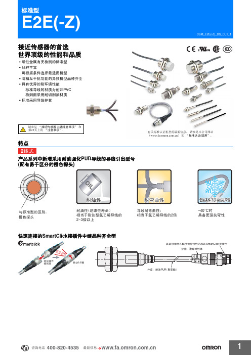
E2E(-Z)
会提示线圈断线等故障及检测不稳定状态的自诊断功能输出型品种齐全
• 有助于实现预防性维护,防止生产线停转。
简化配线过程,降低资源使用,有效减小功耗,助力环保事业
• 配线作业时间及铜线使用量仅为3线式的三分之二。 • 电流消耗量大幅降低至10%以下。 (直流2线式与直流3线式相比)
2mm
导线引出型 (2m)
PVC (耐油) - - PUR (耐油强化) PVC (耐油) PUR (耐油强化)
M12 接插件型 M8 接插件型 M12 SmartClick 接插件中继型 (0.3m)
导线引出型 (2m) M12
3mm
M12 接插件型
PVC (耐油) -
M12 标准接插件中继 型 (0.3m)
3㒓ᓣ
产品系列中包含小口径型号 (3、 4、 5.4、 M5)
• 所有小口径型号均采用屏蔽结构。即使将传感器安装在狭小区域或嵌入金属中,仍然具有较高的工作稳定性。 • 配有明亮醒目的指示灯,轻松查看安装环境。
宽广的使用环境温度 -40~+85C (M8~M30型)
• 小口径型号同样具备宽广的使用温度范围:-25C~+70C • 适用于光电传感器难以胜任的低温和高温应用场合。
ϡᯧফ਼ೈ䞥ሲⱘᕅડ
ሣ㬑ൟ
㓈ᡸֱݏᗻ
ޣᇥᑧᄬ
NPNǃ PNP݅⫼
Ⳉ⌕2㒓ᓣ E2E-XƶDƶ ѸⳈ⌕ϸ⫼2㒓ᓣ E2E-XƶT1 ᦦӊЁ㒻SmartClickൟ E2E-XƶDƶ-M1TGJ-(U) ᦦӊЁ㒻ൟ E2E-XƶD1-M1(G)J-(T) ᦦӊൟ E2E-XƶDƶ-M1(G) E2E-XƶEƶ-M1 E2E-XƶYƶ-M1
飞克 404E、406E、405、408和410激光距离计技术数据说明书

-10℃ to 60℃
Ingress protection
IP54
IP65
Drop test
1m
1m
Size
50 mm × 115mm × 29mm
52 mm × 116mm × 28mm
Weight
100g
110g
* Temperature for specified accuracy is 25°C ** Favorable conditions: white and diffuse reflection objects (white painted walls) ,low background illumination and moderate temperature *** Unfavorable conditions: objects with low or high reflectivity, high background illumination or the temperature is at the upper or lower limit of the specific temperature range
TECHNICAL DATA
Fluke 404E, 406E, 405, 408 and 410
Laser Distance Meter
Features and benefits
● Quickly measure distance, calculate area / volume / pythagoras ● Auto level and height ● Built to withstand rainy or dusty conditions : 1-meter drop tested
奥普士OPTEX普通光电传感器Y系列
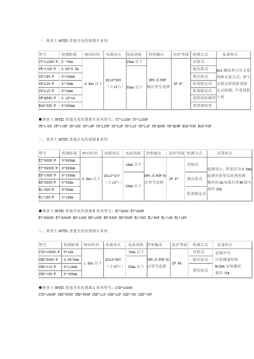
一、奥普士OPTEX普通光电传感器Y系列型号检测距离响应时间电源电压电流消耗控制输出防护等级检测方式显著特点YT-1180N/P 0 -30m0.5ms以下 DC10-30V(±10%)20mA以下NPN或PNP输出型号选择IP 67对射式M18螺纹和方形支架两种安装方式,便于安装长距离距离限定式检测,不受背影干扰YR-140N/P 0.05-3.5m30mA以下镜反射式YD-15N/P 0-400mm 漫反射式YD-L2N/P 0-43mm 距离限定式YD-L1N/P 0-16mm 距离限定式YR-Q39N/P 0.15-1m 透明体检测型BGS-Y8N/P 0-200mm 背景抑制型●奥普士OPTEX普通光电传感器Y系列型号:YT-1180N YT-1180PYR-140N YR-140P YD-15N YD-15P YD-L2NP YD-L2P YD-L1N YD-L1P YR-Q39N YR-Q39P BGS-Y8N BGS-Y8P二、奥普士OPTEX普通光电传感器E系列型号检测距离响应时间电源电压电流消耗控制输出防护等级检测方式显著特点ET-500N/P 0-500mm0.5ms以下 DC12-24V(±10%)16mA以下NPN或PNP输出型号选择IP 67对射式超薄设计,厚度仅为3.5mm超薄对射型长距离检测独有的2m电缆自带M8接头重约20gET-S500N/P 0-500mmED-100N/P 0-100mm20mA以下漫反射式ED-S30N/P 0-30mmEL-30N/P 5-30mm距离限定式EL-15N/P 2-15mm●奥普士OPTEX普通光电传感器E系列型号:ET-500N ET-500PET-S500N ET-S500P ED-100N ED-100P ED-S30N ED-S30P EL-30N EL-30P EL-15N EL-15P三、奥普士OPTEX普通光电传感器C系列型号检测距离响应时间电源电压电流消耗控制输出防护等级检测方式显著特点CTD-1500N/P 0-15m1.5ms以下 DC10-30V(±10%)40mA以下NPN或PNP输出型号选择IP 66对射式金属外壳可检测透明体M18mm安装螺纹重约40gCRD-300N/P 0.05-3mm30mA以下镜反射式CDD-11N/P 0-110mm漫反射式CDD-40N/P 0-400mm●奥普士OPTEX普通光电传感器C系列型号:CTD-1500NCTD-1500P CRD-300N CRD-300P CDD-11N CDD-11P CDD-40N CDD-40P四、施克/奥普士SICK/OPTEX光电传感器J系列型号检测距离响应时间电源电压电流消耗控制输出防护等级检测方式显著特点JT-S/H1000N/P 0-10m0.5 ms以下DC10-30V(±10%) 20mA以下NPN或PNP输出型号选择IP 67对射式内部树脂填充构造,超强的耐水、防油保护超小物体稳定检测(Φ2mm@100mm)超强的抗干扰性JR-S/H300N/P 0-3m 镜反射式JD-S/HR80N/P 0-800mm漫反射式JD-S/HW80N/P 0-80mmJD-S/HL03N/P 20-50mm 距离限定式JR-S/HQ50N/PW 20-500mm 2.5ms/0.5ms 40mA以下透明体检测型●奥普士OPTEX普通光电传感器J系列型号:JT-S1000N JT-S1000P JT- H1000NJT-H1000P JR-S300N JR-S300P JR-H300N JR-H300P JD-SR80N JD-SR80P JD-HR80NJD-HR80P JD-SW80N JD-SW80P JD-HW80N JD-HW80P JD-SL03N JD-SL03P JD-HL03N JD-HL03P JR-SQ50NWJR-SQ50PW JR-HQ50NW JR-HQ50PW五、奥普士OPTEX普通光电传感器J2系列型号检测距离响应时间电源电压电流消耗控制输出防护等级检测方式显著特点J2D-S/H10N/P 5-100mm0.5 ms以下 DC10-30V(±10%) 40mA以下NPN或PNP输出型号选择IP 67漫反射式内部树脂填充构造,超强的耐水、防油保护超小物体稳定检测(Φ2mm@100mm)J2D-S/H100N/P 0-1mJ2D-S/H70N/P 0-700mmBGS-S/H15N/P 50-150mm 2.5ms以下45mA以下背景抑制型●奥普士OPTEX普通光电传感器J2系列型号:J2D-S10N J2D-S10P J2D-H10NJ2D-H10P J2D-S100N J2D-S100P J2D-H100N J2D-H100P J2D-S70N J2D-S70P J2D-H70N J2D-H70P BGS-S15NBGS-S15P BGS-H15N BGS-H15P六、奥普士OPTEX普通光电传感器J3系列型号检测距离响应时间电源电压电流消耗控制输出防护等级检测方式显著特点J3M-GS/H01N/P 8-12mm0.2 ms以下DC10-30V(±10%)40mA以下NPN或PNP输出型号选择IP 67漫反射式内部树脂填充构造,超强的耐水、防油保护超强的抗干扰性J3R-S/H100N/P 0.03-1m 镜反射式BGS-3JS/H05N/P 15-50mm 0.7 ms以下背景抑制型●奥普士OPTEX普通光电传感器J3系列型号:J3M-GS01NJ3M-GS01P J3M-GH01N J3M-GH01P J3R-S100N J3R-S100P J3R-H100N J3R-H100PBGS-3JS05N BGS-3JS05P BGS-3JH05N BGS-3JH05P七、奥普士OPTEX 普通光电传感器K 系列 型号检测距离响应时间 电源电压电流消耗 控制输出 防护等级 检测方式显著特点KT-700N/P 0-7m 1 ms 以下DC10-30V (±10%)35mA 以下NPN 或PNP 输出型号选择IP 67 对射式金属外壳超强防震、抗静电、抗磁场干扰 采用高亮度LED ,超强抗光性 约重25gKR-250N/P 0-2.5m 0.7 ms 以下30mA 以下镜反射式KD-40N/P 0-400mm 漫反射式 KD-L09N/P 10-90mm 距离限定式 KR-Q300N/PW 0-2.5m 透明体检测型 KR-Q150N/PW 0-1.5m 透明体检测型 KR-Q50N/P (W ) 10-500mm透明体检测型●奥普士OPTEX 普通光电传感器K 系列型号:KT-700N KT-700PKR-250N KR-250P KD-40N KD-40P KD-L09N KD-L09P KR-Q300NW KR-Q300PW KR-Q150NW KR-Q150PW KR-Q50N KR-Q50NW KR-Q50P KR-Q50W八、施克/奥普士SICK/OPTEX 普通光电传感器BGS-Z 系列 型号 检测距离 响应时间 电源电压电流消耗 控制输出 防护等级检测方式显著特点BGS-Z10N/P 5-100mm 0.5 ms 以下 DC10-30V (±10%)30mA以下NPN 或PNPIP 67 背景抑制型 达到0.25msBGS-Z30N/P 10-300mm●奥普士OPTEX 普通光电传感器BGS-Z 系列型号:BGS-Z10N BGS-Z10P BGS-Z30N BGS-Z30P九、奥普士OPTEX 普通光电传感器D 系列 型号 检测距离 响应时间 电源电压 电流消耗 控制输出防护等级 检测方式 显著特点DT-4000N/P 0-40m 0.5 ms 以下DC10-30V(±10%)30mA以下NPN 或PNP 输出型号选择IP 67对射式同轴激光光源,安装更方便,定位更精确数位显示,操作更方便具有自动感度调整 约20gDR-500N/P 0-4.5m 镜反射式 DR-Q150TN/P 0-1.5m 0.7 ms 以下 透明体检测型DR-Q400TN/P 0-4m BGS-DL10TN/P 40-100mm 1.5 ms 以下 35mA 以下背景抑制型 BGS-DL25TN/P 100-250mm●奥普士OPTEX 普通光电传感器D 系列型号:DT-4000N DT-4000PDR-500N DR-500P DR-Q150TN DR-Q150TP DR-Q400TN DR-Q400TP BGS-DL10TN BGS-DL10TP BGS-DL25TN BGS-DL25TP十、奥普士OPTEX 普通光电传感器V 系列 型号检测距离响应时间电源电压电流消耗控制输出 防护等级 检测方式显著特点VT-4000(T ) 0-40m 20 ms 以下 DC12-240V 或AC24-240V (±10%)5VA继电器输出IP 67对射式 红色LED 实现,长距离检出 自由选择供给电源 继电器输出或晶体管输出自由选择VR-1000(T ) 0-10m 镜反射式 VD-130(T ) 0-1.3m 漫反射式 VD-300(T ) 0-3m VT-3000N/P 0-30m 1.5 ms 以下DC10-30V (±10%)35mA 以下NPN 或PNP 输出型号选择对射式 VR-800N/P 0-8m 镜反射式 VD-100N/P 0-1m 漫反射式VD-250N/P 0-2.5m●奥普士OPTEX 普通光电传感器V 系列型号:VT-4000 VT-4000TVR-1000 VR-1000T VD-130 VD-130T VD-300 VD-300T VT-3000N VT-3000P VR-800N VR-800P VD-100N VD-100P VD-250N VD-250P十一、施克/奥普士SICK/OPTEX 普通光电传感器V2系列 型号检测距离响应时间 电源电压电流消耗控制 输出防护等级 检测方式 显著特点V2T-2000-3A 0-20m 15 ms 以下 DC12-240V 或AC24-240V (±10%)5VA继电器输出IP 67对射式 红色LED 实现,长距离检出 自由选择供给电源继电器输出或晶体管输出自由选择V2R-800-3A 0-8m 镜反射式BGS-V80 250-800mm 背景抑制型BGS-V50 150-500mm BGS-V30 100-300mm V2T-2000N/P 0-20m 1 ms 以下 DC10-30V (±10%)35mA 以下 NPN 或PNP 输出型号选择对射式V2R-800N/P 0-8m 0.7 ms 以下镜反射式 BGS-V80N/P 250-800mm 3 ms 以下 背景抑制型 BGS-V50N/P 150-500mm 2 ms 以下 BGS-V30N/P 100-300mm BGS-30N/P 100-300mm BGS-10N/P 40-100mm奥普士OPTEX 普通光电传感器V2系列型号:V2T-2000-3AV2R-800-3A BGS-V80 BGS-V50 BGS-V30 V2T-2000N V2T-2000P V2R-800N V2R-800P BGS-V80N BGS-V80P BGS-V50N BGS-V50P BGS-V30N BGS-V30P BGS-30N BGS-30P BGS-10N BGS-10P十二、奥普士OPTEX普通光电传感器V3/V4系列型号检测距离响应时间电源电压电流消耗控制输出防护等级检测方式显著特点V3T-4000 0-40m20ms以下DC12-240V或AC24-240V(±10%)对射式9.5VA;其他5VA继电器输出IP66对射式V3系列电缆式V3R-1000 0-10m 镜反射式V3D-130 0-1.3m 漫反射式V4T-4000 0-40m 对射式V4系列端子式V4R-1000 0-10m 镜反射式V4D-130 0-1.3m 漫反射式●奥普士OPTEX普通光电传感器V3/V4系列型号:V3T-4000V3R-1000 V3D-130V4T-4000 V4R-1000 V4D-130十三、奥普士OPTEX普通光电传感器Z系列型号检测距离响应时间电源电压电流消耗控制输出防护等级检测方式显著特点ZT-1200N/P 0-12m0.5ms以下DC10-30V(±10%)20mA以下NPN或PNP输出型号选择IP67对射式0.5ms以下高速应答最新推出同轴镜面反射型,适应各方面的安装场合适应各种环境抗干扰能力强ZR-350N/P 0-3.5m 镜反射式ZD-70N/P 0-700mm 漫反射式ZD-W20N/P 1-200mm 宽角度漫反射式ZD-L09N/P 10-90mm 距离限定式ZR-Q2000N/P 0.01-2m 透明体检测型ZR-QX200N/P 0-2m 同轴透明体检测型ZR-X250N/P 0-2.5m 0.25ms以下同轴镜反射式●奥普士OPTEX普通光电传感器Z系列型号:ZT-1200N ZT-1200PZR-350N ZR-350P ZD-70N ZD-70P ZD-W20N ZD-W20P ZD-L09N ZD-L09P ZR-Q2000N ZR-Q2000P ZR-QX200N ZR-QX200P ZR-X250N ZR-X250P十四、施克/奥普士SICK/OPTEX普通光电传感器ZL系列型号检测距离响应时间电源电压电流消耗控制输出防护等级检测方式显著特点ZT-L3000N/P 0-30m0.25ms以下DC10-30V(±10%)30mA以下NPN或PNP输出型号选择IP67对射式激光光源,光斑小体积小响应时间快,可达到0.25msZR-L1000N/P 0.08-10m 镜反射式ZD-L40N/P 0-400mm 漫反射式BGS-ZL30N/P 100-300mm背景抑制型BGS-ZL10N/P 5-100mm奥普士OPTEX普通光电传感器ZL系列型号:ZT-L3000NZT-L3000P ZR-L1000N ZR-L1000P ZD-L40N ZD-L40P BGS-ZL30N BGS-ZL30P BGS-ZL10NBGS-ZL10P十五、奥普士OPTEX普通光电传感器Z2系列型号检测距离响应时间电源电压电流消耗控制输出防护等级检测方式显著特点Z2T-2000N/P 0-25m0.5ms以下DC10-30V(±10%)15mA以下NPN或PNP输出型号选择IP67对射式0.5ms以下高速应答最新推出同轴镜面反射型Z2R-400N/P 0.01-4.4m 镜反射式Z2D-80N/P 0-1m 漫反射式奥普士OPTEX普通光电传感器Z2系列型号:Z2T-2000N Z2T-2000P Z2R-400NZ2R-400P Z2D-80N Z2D-80P十六、奥普士OPTEX普通光电传感器Z-M系列型号检测距离响应时间电源电压电流消耗控制输出防护等级检测方式显著特点ZT-M3000N/P 0-30m0.5ms以下DC10-30V(±10%)15mA以下NPN或PNP输出型号选择IP69K对射式耐高温高水压适合生肉生鲜食品IP系数69KZR-M550N/P 0.01-5.5m18mA以下镜反射式ZD-M80N/P 0-800mm 漫反射式BGS-ZM10N/P 20-100mm28mA以下背景抑制型BGS-ZM30N/P 20-300mm●奥普士OPTEX普通光电传感器Z-M系列型号:ZT-M3000NZT-M3000P ZR-M550N ZR-M550P ZD-M80N ZD-M80P BGS-ZM10N BGS-ZM10P BGS-ZM30N BGS-ZM30P十七、奥普士OPTEX 普通光电传感器S 系列 型号检测距离响应时间电源电压电流消耗控制输出防护等级 检测方式 显著特点ST-400N/P 0-4m 0.5ms 以下DC10-30V (±10%)30mA 以下NPN 或PNP 输出型号选择IP67对射式 达到CE 标准的最小体积 0.5ms 以下高速应答重约5g SR-150N/P0-1.5m20mA 以下镜反射式SD-20N/P0-200mm漫反射式BGS-S08N/P 10-80mm背景抑制型 SR-Q50N/PW 10-500mm透明体检测型●奥普士OPTEX 普通光电传感器S 系列型号:ST-400N ST-400PSR-150N SR-150P SD-20N SD-20P BGS-S08N BGS-S08P SR-Q50N SR-Q50PW十八、奥普士OPTEX 普通光电传感器C2系列 型号 检测距离 响应时间电源电压电流消耗控制输出 防护等级检测方式 显著特点 C2TP-2000N/P 0-20m 0.5ms 以下DC10-30V (±10%)20mA 以下 NPN 或PNP输出型号选择IP67对射式 塑料外壳 可检测透明体M18mm 安装螺纹重约40g C2RP-F400N/P 0.01-4m 镜反射式C2RP-350N/P 0.01-3.5m C2DP-11N/P 0-110mm 漫反射式 C2DP-40N/P 0-400mm C2DP-80N/P 0-800mm C2TM-2000N/P 0-20m 对射式 金属外壳 可检测透明体M18mm 安装螺纹重约40gC2RM-F400N/P 0.01-4m 镜反射式C2RM-350N/P 0.01-3.5m C2DM-11N/P 0-110m 漫反射式 C2DM-40N/P 0-400mm C2DM-80N/P 0-800mm奥普士OPTEX 普通光电传感器C2系列型号:C2TP-2000N C2TP-2000PC2RP-F400N C2RP-F400P C2RP-350N C2RP-350P C2DP-11N C2DP-11P C2DP-40N C2DP-40P C2DP-80N C2DP-80P C2TM-2000N C2TM-2000P C2RM-F400N C2RM-F400P C2RM-350N C2RM-350P C2DM-11N C2DM-11P C2DM-40N C2DM-40P C2DM-80N C2DM-80P十九、奥普士OPTEX普通光电传感器S2系列型号检测距离响应时间电源电压电流消耗控制输出防护等级检测方式显著特点S2T-1200N/P 0-12m1.5ms以下DC10-30V(±10%)20mA以下NPN或PNP输出型号选择IP67对射式实现小体积长距离检出0.5ms以下高速应答防水构造重约5gS2R-350N/P 0.01-3.5m 镜反射式S2D-80N/P 0-800mm 漫反射式BGS-2S15N/P 25-150mm30mA以下背景抑制型BGS-2S30N/P 25-300mm●奥普士OPTEX普通光电传感器S2系列型号:S2T-1200N S2T-1200P S2R-350NS2R-350P S2D-80N S2D-80P BGS-2S15N BGS-2S15P BGS-2S30N BGS-2S30P二十、奥普士OPTEX光电传感器V2new系列型号检测距离响应时间电源电压电流消耗控制输出防护等级检测方式显著特点V2T-7000DN/P 0-70m 1ms以下晶体管DC10-30V(±10%)35mA以下NPN或PNP输出型号选择IP67对射式红色LED实现长距离检出自由选择供给电源继电器输出或晶体管输出自由选择V2R-1500DN/P 0-15m 0.7ms以下镜反射式BGS-2V30N/P 10-30mm2ms以下背景抑制型BGS-2V50N/P 15-50mmBGS-2V100N/P 30-100mmV2T-7000(H)0-70m 1ms以下DC12-240V或AC24-240V (±10%)对射式9.5VA;其他5VA继电器输出对射式V2R-1500(H)0-15m 0.7ms以下镜反射式BGS-2V30(H)10-30mm2ms以下背景抑制型BGS-2V50(H)15-50mmBGS-2V100(H)30-100mm●奥普士OPTEX普通光电传感器V2new系列型号:V2T-7000DN V2T-7000DPV2R-1500DN V2R-1500DP BGS-2V30N BGS-2V30P BGS-2V50N BGS-2V50P BGS-2V100N BGS-2V100P V2T-7000 V2T-7000H V2R-1500 V2R-1500H BGS-2V30 BGS-2V30H BGS-2V50 BGS-2V50H BGS-2V100 BGS-2V100H二十一、奥普士OPTEX 位移传感器CD5系列 型号 检测距离测量范围电源电压电流消耗光源防护等级检测方式 显著特点CD5-L25 25mm ±1mmDC12-240V (±10%)或来自控制器红色激光二极管IP 67镜面反射高灵敏度的线性图像传感器 低象差镜头 高速处理单元 宽光点型 预防串扰 3个传感器的多重运算 CD5-LW25 CD5-30 30mm±5mm漫反射 CD5-W30 CD5-85 85mm ±20mm CD5-W85 CD5-W350 350mm ±100mm CD5-W500 500mm ±200mm CD5-W2000 2000mm ±500mm CD5A-N350mA/24VIP 20CD5A-P奥普士OPTEX 位移传感器CD5系列型号:CD5-L25 CD5-LW25 CD5-30 CD5-W30 CD5-85 CD5-W85 CD5-W350 CD5-W500 CD5-W2000 CD5A-N CD5A-P二十二、施克/奥普士SICK/OPTEX 位移传感器CD4/CD1/CD3/CD33系列 型号 测量范围 线性精度电源电压分辨率 最小光斑 显著特点CD4-L25(J) 25±1mm ±0.1%F.S.专用处理器供电0.1μm 约25×35μm不同反射程度的材质表面的稳定检测可见小光点激光光束 具备1个放大器2个传感器头稳定的红、黄、绿功能输出指示灯4个模拟量5个开关量输出 通过RS232与PC 连接可实时观测测量数据 CD4-L30(J) 30±5mm1μm约30×100μmCD4-L30(J)-3R CD4-L85(J) 85±20mm3μm约70×290μmCD4-L85(J)-3R CD4-L350(J) 350±100mm 40μm 约300×700μm CD4-L350(J)-3R CD4A-N DC12-24V (±10%)CD4A-P CD4A-LN CD4A-LP CD1-30N 30±4mm ±2%F.S. 3μm Φ0.5mm 采用PSD 感光元件,操作简单CD1-100N 100±35mm ±2%F.S. 50μm 1×1.5mm CD1-250N 250±150mm ±5%F.S. 500μm 1.5×3mm CD3-30N 30±4mm ±1%F.S. 4μm Φ0.5mm CCD 感光元件,可稳定检测黑色物体,带数字显面板 CD3-100N 100±40mm ±12%F.S.30μm 1×1.5mm CD3-250N 250±150mm±1.5%F.S.150μm1.5×3mm奥普士OPTEX 位移传传感器CD4系列型号:CD4-L25(J) CD4-L30(J) CD4-L30(J)-3R CD4-L85(J) CD4-L85(J)-3R CD4-L350(J)CD4-L350(J)-3R CD4A-N CD4A-P CD4A-LN CD4A-LP CD1-30N CD1-100N CD1-250N CD3-30N CD3-100N CD3-250N二十三、施克/奥普士SICK/OPTEX 位移传感器CD33系列 型号检测距离 测量范围 分辨率 线性度 检测方式检测项目 显著特点CD33-L30N-422 26.3±2mm 1μm 正反射型数字子像素处理 电压和电流输出易选型测量范围的2通道输出可独立设置 高分辨率电子快门 简易操作 CD33-L50N-422 47.3±5mm2.5μmCD33-L85N-42282.9±10mm 5μmCD33-30NV(PV) 30mm30±4mm4μm±0.1%F.S距离型PC 版的翘曲/下垂检测 CD33-30NA(PA) CD33-50NV(PV)50mm50±10mm8μm电路板上零件高度检测 CD33-50NA(PA)CD33-85NV(PV) 85mm85±20mm15μm橡胶板的联合处检测 CD33-85NA(PA) CD33-120NV(PV) 120mm120±60mm45μm橡胶板的松散检测CD33-120NA(PA)奥普士OPTEX 位移传感器CD33系列型号:CD33-L30N-422 CD33-L50N-422CD33-L85N-422 CD33-30NV CD33-30PV CD33-30NA CD33-30PA CD33-50NV CD33-50PV CD33-50NA CD33-50PA CD33-85NV CD33-85PV D33-85NA CD33-85PA CD33-120NV CD33-120PV D33-120NA CD33-120PA二十五、施克/奥普士SICK/OPTEX 色标传感器系列 型号 检测范围 检测方式 显著特点DM-18T 18+/-2mm 采用RGB 三色光源,颜色分辨更细致,而且三色光源可切换 J3M-GH01N 10+/-2mm 采用业界最小的高亮度绿色LED ,投光4阶段调整,安定检出 树脂充填设计,高防护等级,耐水抗油性强J3M-GS01N RT-1500 1.5m 对射型请根据检测要求,选择任意一种检测头与RSA 放大器搭配使用RT-F300 300mm RD-150 150mm 漫反射型RD-F50 50mm RS-20R 20+/-2mm RS-16G 16+/-1mm RM-16R 16+/-2mm RM-16G 16+/-1mm奥普士OPTEX 色标传感器系列型号:DM-18T J3M-GH01NJ3M-GS01N RT-1500 RT-F300 RD-150 RD-F50 RS20R RS-16G RM-16R RM-16G二十四、奥普士OPTEX 放大器分离型激光传感器系列 型号检测距离 光斑电源电压 指示灯防护等级 显著特点DSR-800Long 模式:0-8mStandard 模式:0-5mFast 模式:0-2m Φ2mm/距离2m激光发射指示灯:绿色LED 输出指示灯:橙色LEDIP67高精度8位数显同轴激光放大器分离型光电传感器可进行点、线、面的检测(光束可自行选择) 70M 超远距离检测 Φ1mm 的最小光点双信道独立输出,独立模拟量输出(4-20mA )放大器可扩展50PCS ,可省配线,还可与D2RF 、B2RF 连接以省配线 自带计数功能60μs 高速响应,延时可设定1ms-9sDSR-5000Long 模式:0.5-50mStandard 模式:0.3-35m Fast 模式:0.1-20m Φ2mm/距离2mDSD-100Long 模式:1m Standard 模式:0.7m Fast 模式:0.25mΦ1mm/距离1mDSTC-200 2mΦ2mm/距离2mIP50DSTC-200- M8 DSTA-200 2m 30*2.5mm/距离2m DSTA-200-M8D2SA-MNS DC12-24V (10%)激光发射指示灯:绿色 输出指示灯:橙色D2SA-MN D2SA-SN D2SA-MN3S D2SA-MNS-M8 D2SA-MN3S D2SA-MN3S-M8 D2SA-SN1 D2SA-SN-M8奥普士OPTEX 放大器分离型激光传感器系列型号:DSR-800DSR-5000 DSD-100 DSTC-200- M8 DSTA-200 DSTA-200-M8 D2SA-MNS D2SA-MN D2SA-SN D2SA-MN3S D2SA-MNS-M8 D2SA-MN3S D2SA-MN3S-M8 D2SA-SN1 D2SA-SN-M8二十六、奥普士OPTEX 放大器分离式光纤传感器系列 型号 控制输出电源电压光源消耗电流种类防护等级显著特点D2RF-TN 2CH 输出:CH1:NPN 或PNP 输出CH2:报警输出或外部输入DC12-24V (±10%)红色LED24V 时,45mA 以下单独型IP50双数显两种状态,八位数字对比显示 独立的两信道输出功能60μS 快速响应速度 功能强大的ASC/APC 自动调节功能,不受苛刻恶劣环境影响 多种检测模式适用于各种检测物D2RF-TCN4 D2RF-TMN 连接型主机D2RF-TMCN4 D2RF-TSN 连接型子机D2RF-TSCN4 D2GF-TN 绿色LED单独型D2GF-TCN4 D2GF-TMN 连接型主机D2GF-TMCN4 D2GF-TSN 连接型子机 D2GF-TSCN4 D2RF-TAN NPN 输出或PNP 输出 红色LED 单独型模拟量输出型 NF-DB01 最宽的显示屏 更简单的操作 更直观的辨认显示数值超远感应距离NF-DR01 NF-DH01 NF-TB01 NF-TR01 NF-TH01D3RF-TN NPN 输出DC12-24V (±10%)红色LED正常模式:DC24V 时,1信道输出36mA ,2信道输出39mA 省电模式: DC24V 时,1信道输出25mA ,2信道输出28mA个体式IP50 D3RF-TDN D3RF-TMN 分体式-主机 D3RF-TDMN D3RF-TSN 分体式-副机D3RF-TDSNVRF-N(P) NPN 或PNP 输出 DC10-30V (±10%)红色LED单独型:12V 时,25mA 以下 连接型: 12V 时, 35mA 以下标准型IP6610圈灵敏度调整,灵敏度更线性化 独特的光纤插入到位指引,设计更人性化 BIF 独特的水分检测功能VRF-CN(P) VRF-HN(P) 高速应答型 VRF-HCN(P) JRF-N(P) 防水型JRF-CN(P) BRF-N(P) 标准型 B2RF-N(P) BRF-CN(P)B2RF-CN(P) BRF-HN(P) 高速应答型B2RF-HN(P) BRF-CHN(P) B2RF-CHN(P) BGF-N(P) 绿色LED色标检测型 B2GF-N(P) BGF-CN(P) B2GF-CN(P) BIF-N(P) 红色LED水分检测型B2IF-N(P) BIF-CN(P) B2IF-CN(P) NF-DR06 NF-TS12 NF-DT01 NF-TS14 NF-DV01 NF-TY01 NF-TS24 NF-TH05S NF-TS22M NF-DC02奥普士OPTEX 放大器分离式光纤传感器系列型号:D2RF-TN D2RF-TCN4 D2RF-TMN D2RF-TMCN4 D2RF-TSN D2RF-TSCN4 D2GF-TN D2GF-TCN4 D2GF-TMN D2GF-TMCN4 D2GF-TSN D2GF-TSCN4 D2RF-TAN NF-DB01 NF-DR01 NF-DH01 NF-TB01 NF-TR01 NF-TH01 D3RF-TN D3RF-TDN D3RF-TMN D3RF-TDMN D3RF-TSN D3RF-TDSN VRF-N VRF-P VRF-CN VRF-CP VRF-HN VRF-HP VRF-HCN VRF-HCP JRF-N JRF-P JRF-CN JRF-CP BRF-N BRF-P B2RF-N B2RF-P BRF-CN BRF-CP B2RF-CN B2RF-CP BRF-HN BRF-HP B2RF-HN B2RF-HP BRF-CHN BRF-CHP B2RF-CHN B2RF-CHP BGF-N BGF-P B2GF-N B2GF-P BGF-CN BGF-CP B2GF-CN B2GF-CP BIF-N BIF-P B2IF-N B2IF-P BIF-CN BIF-CP B2IF-CN B2IF-CP NF-DR06 NF-TS12 NF-DT01 NF-TS14 NF-DV01 NF-TY01 NF-TS24 NF-TH05S NF-TS22M NF-DC02二十七、奥普士OPTEX图像传感器系列型号摄影角度焦点距离摄影面积消耗电流电源电压防护等级检测方式显著特点CVS1-N10-R 10度210-270mm 40×50-55×65mm最大120mA/24VDC DC12-24V(±10%)IP67长距离检测型体积小安装方便对色面积能广泛检测CVS1-N20-R 20度90-150mm 40×50-65×75mm 标准检测型CVS1-N40-R 40度50-100mm 50×65-100×115mm 近距离宽角度检测型CVS2-N10-R 10度210-270mm 40×50-55×65mm 长距离检测型CVS2-N20-R 20度90-150mm 40×50-65×75mm 标准检测型CVS2-N40-R 40度50-100mm 50×65-100×115mm 近距离宽角度检测型CVS3-N20-R20度90-150mm 40×50-65×75mm标准检测型CVS3-N21-R 35+/-4mm 17×20mm 狭视界检测型CVS4-N20-R20度90-150mm 53×25-79×38mmCVS4-N21-R 35+/-4mm 21×10mmCVS4-N23-R50+/-6mm 30×15mmCVS4-N23R-RMVS-PM 最大10mA/24VDC DC6±10%IP50 MVS-DN最大80 mA/24VDC DC24±10%IP20 MVS-DP奥普士OPTEX图像传感器系列型号:CVS1-N10-R CVS1-N20-R CVS1-N40-R CVS2-N10-R CVS2-N20-R CVS2-N40-R CVS3-N20-R CVS3-N21-R CVS4-N20-R CVS4-N21-R CVS4-N23-R CVS4-N23R-R MVS-PM MVS-DN MVS-DP二十八、奥普士OPTEX形状识别传感器系列型号检测范围受光范围电源电压电流消耗光源防护等级显著特点SHP-100CN 100±25mm 宽17mm/距离75mm宽27mm/距离125mmDC12-24V(±10%)120mA 0.3mm×32mm IP50长距离、宽范围、超高速取样、高精度测量同时具备3个开关量和1个模拟量输出奥普士OPTEX形状识别传感器系列型号:SHP-100CN 二十九、奥普士OPTEX视觉传感器系列型号CPU SDRAM FLASH ROM 输出图像绝缘型I/O电源显著特点TA-3000系列TI DSP TMS320DM642:720MHz 128MB 133MHz 4MB NTSC or VGA每个16点DC+24V软件包:TA硬件:高速图像处理系统TA-3100系列VGA DC+12V (AC/DC 电源转接器)TA-4610系列TI DSP TMS320DM642:720MHzDSP组件盘:最多可以搭配8个128MB(每个DSP组件盘)8MB VGA每个8点(MAX:32点)AC100-240(有关闭开关)。
C8051F530A开发板用户指南说明书

Rev. 0.4 11/14Copyright © 2014 by Silicon LaboratoriesC8051F53x/52xEVELOPMENT IT SER S UIDE1. Relevant DevicesThe C8051F530 Development Kit is intended as a development platform for microcontrollers in the C8051F53x/52x MCU family. Code developed on the C8051F530 can be easily ported to the other members of this MCU family.2. Kit ContentsThe C8051F530 Development Kit contains the following items:⏹ C8051F530A Target Board⏹ C8051Fxxx Development Kit Quick-Start Guide ⏹ AC to DC Power Adapter⏹ USB Debug Adapter (USB to Debug Interface)⏹ USB CableThe development kit target board contains two C8051F530 microcontrollers that can communicate through an LIN network. One of the C8051F530 (U2) can also be connected to a CP2102 USB to UART bridge and directly connected to two analog signals and a Voltage Reference Signal Input.3. Hardware Setup Using a USB Debug AdapterThe target board is connected to a PC running the Silicon Laboratories IDE via the USB Debug Adapter as shown in Figure 1.1. Connect the USB Debug Adapter to one of the DEBUG connectors on the target board (HDR1 or HDR2) with the 10-pin ribbon cable. The recommended connection is to the HDR2 (connected to U2) as this microcontroller can be connected to the CP2102 USB to UART bridge.2. Verify that shorting blocks are installed on J13 and J14 to supply power to the target devices.3. Connect one end of the USB cable to the USB connector on the USB Debug Adapter.4. Connect the other end of the USB cable to a USB Port on the PC.5. Connect the ac/dc power adapter to power jack P5 on the target board.D 1D 2H H D 4C8051F53x/52xNotes:e the Reset button in the IDE to reset the target when connected using a USB Debug Adapter.2. Remove power from the target board and the USB Debug Adapter before connecting or disconnecting theribbon cable from the target board. Connecting or disconnecting the cable when the devices have power can damage the device and/or the USB Debug Adapter.4. Software SetupSimplicity Studio greatly reduces development time and complexity with Silicon Labs EFM32 and 8051 MCU products by providing a high-powered IDE, tools for hardware configuration, and links to helpful resources, all in one place.Once Simplicity Studio is installed, the application itself can be used to install additional software and documentation components to aid in the development and evaluation process.Figure 2.Simplicity StudioThe following Simplicity Studio components are required for the C8051F530 Development Kit:⏹ 8051 Products Part Support ⏹ Simplicity Developer PlatformDownload and install Simplicity Studio from /8bit-software or /simplicity-studio .Once installed, run Simplicity Studio by selecting Start →Silicon Labs →Simplicity Studio →Simplicity Studio from the start menu or clicking the Simplicity Studio shortcut on the desktop. Follow the instructions to install the software and click Simplicity IDE to launch the IDE.The first time the project creation wizard runs, the Setup Environment wizard will guide the user through the process of configuring the build tools and SDK selection.C8051F53x/52xIn the Part Selection step of the wizard, select from the list of installed parts only the parts to be used during development. Choosing parts and families in this step affects the displayed or filtered parts in the later device selection menus. Choose the C8051F53x/52x family by checking the C8051F53x/52x check box. Modify the part selection at any time by accessing the Part Management dialog from the Window →Preferences →Simplicity Studio →Part Management menu item.Simplicity Studio can detect if certain toolchains are not activated. If the Licensing Helper is displayed after completing the Setup Environment wizard, follow the instructions to activate the toolchain.4.1. Running BlinkyEach project has its own source files, target configuration, SDK configuration, and build configurations such as the Debug and Release build configurations. The IDE can be used to manage multiple projects in a collection called a workspace. Workspace settings are applied globally to all projects within the workspace. This can include settings,such as key bindings, window preferences, and code style and formatting options. Project actions, such as build and debug, are context-sensitive. For example, the user must select a project in the Project Explorer view in order to build that project.To create a project based on the Blinky example, perform the following steps:1. Click the Software Examples tile from the Simplicity Studio home screen.2. In the Kit drop-down, select C8051F530A Development Kit ; in the Part drop-down, select C8051F530, and in the SDK drop-down, select the desired SDK. Click Next .3. Select Example , and click Next .4. Under C8051F530A Development Kit , select F52x-53x Blinky ; click Next , and click Finish .5. Click on the project in the Project Explorer , and click Build (the hammer icon in the top bar). Alternatively, go to Project →Build Project .6. Click Debug to download the project to the hardware and start a debug session.7. Press the Resume button to start the code running. The LED should blink.8. Press the Suspendbutton to stop the code.9. Press the Reset the devicebutton to reset the target MCU.10. Press the Disconnectbutton to return to the development perspective.4.2. Simplicity Studio HelpSimplicity Studio includes detailed help information and device documentation within the tool. The help containsdescriptions for each dialog window. To view the documentation for a dialog, click the question mark icon in the window:This will open a pane specific to the dialog with additional details.The documentation within the tool can also be viewed by going to Help →Help Contents or Help →Search .C8051F53x/52x4.3. CP210x USB to UART VCP Driver InstallationThe Target Board includes a Silicon Labs CP210x USB-to-UART Bridge Controller. Device drivers for the CP210x need to be installed before the PC software can communicate with the MCU through the UART interface.1. After opening Simplicity Studio for the first time, a dialog will prompt to install the CP210x drivers. Click Yes . The drivers can also be installed at any time by going to Help →Install Drivers →CP210x VCP USB Drivers .2. Accept the license agreement and follow the steps to install the driver on the system. The installer will let you know when your system is up to date. The driver files included in this installation have been certified by Microsoft.3. To complete the installation process, connect the included USB cable between the host computer and the USB connector (P4) on the Target Board. Windows will automatically finish the driver installation. Information windows will pop up from the taskbar to show the installation progress.4. If necessary, the driver files can be uninstalled by selecting Windows Driver Package—Silicon Laboratories...option in the Programs and Features window.4.4. Configuration Wizard 2The Configuration Wizard 2 is a code generation tool for all of the Silicon Laboratories devices. Code is generated through the use of dialog boxes for each of the device's peripherals.Figure 3.Configuration Wizard 2 UtilityThe Configuration Wizard 2 utility helps accelerate development by automatically generating initialization source code to configure and enable the on-chip resources needed by most design projects. In just a few steps, the wizard creates complete startup code for a specific Silicon Laboratories MCU. The program is configurable to provide the output in C or assembly language. For more information, refer to the Configuration Wizard documentation.Documentation and software is available on the kit CD and from the downloads web page: /mcudownloads .C8051F53x/52x 5. Target BoardThe C8051F52xA-53xA Development Kit includes a target board with two C8051F530A devices preinstalled for evaluation and preliminary software development. Numerous input/output (I/O) connections are provided to facilitate prototyping using the target board. Refer to Figure4 for the locations of the various I/O connectors.Table 1. Target Board Part SummaryPart DescriptionP5 Power connector (Accepts input from 7 to 15VDC unregulated power adapter.)PWR Red Power-on LED (D3)TB1 LINconnectorU55V Voltage RegulatorA SideJ2 28-pin Expansion I/O connector for U2HDR2 Debug connector for Debug Adapter Interface(D2)P1.3_A GreenLEDbuttonReset_A ResetbuttonP1.4_A PushR32Potentiometer for P1.2_AJ6, J8Connects R32 (potentiometer) to U2 and +5 VJ13Connects power to U2J11, J12Connects external crystal to U2 pins P0.7_A and P1.0_AJ3 Connects analog channel 1 to U2 P1.6_AJ4 Connects analog channel 2 to U2 P1.7_AJ5 Connects VREFIN to U2 P0.0_AconnectorTB2 AnaloginputHDR4 Connector block for serial port connection, Green LED, and push-buttonU3Silicon Laboratories CP2102 USB-to-UART BridgeP1 USB connector to serial interface (CP2102)USB ACTIVE Red USB Active LED (D4) (CP2102)T2 LINtransceiverU2 C8051F530A “A” SideC8051F53x/52x5.1. Target Board Shorting Blocks: Factory DefaultsThe C8051F530A target board comes from the factory with preinstalled shorting blocks on many headers. Figure 4shows the positions of the factory default shorting blocks.B SideJ1 26-pin Expansion I/O connector for U1HDR1Debug connector for Debug Adapter InterfaceP1.3_B Green LED (D1)Reset_B Reset button P1.4_B Push button J14Connects power to U1J9, J10Connects external crystal to U1 pins P0.7_B and P1.0_B HDR3Green LED and push-button connector blockT1 LIN transceiver U1C8051F530A “B” SideTable 1. Target Board Part SummaryPart DescriptionP1.4_BPWRUSB ACTIVE P1.3_AP1.3_B D2D1D4Pin 1C8051F53x/52x5.2. System Clock SourcesThe C8051F530A device installed on the target board features a calibrated programmable internal oscillator that is enabled as the system clock source on reset. After reset, the internal oscillator operates at a frequency of 191.4kHz (±0.5%) by default but may be configured by software to operate at other frequencies. Therefore, in many applications, an external oscillator is not required. However, if you wish to operate the C8051F530A device at a frequency not available with the internal oscillator, an external crystal may be used. Refer to the C8051F52x/ 52xA/53x/53xA data sheet for more information on configuring the system clock source.The target board is designed to facilitate the installation of external crystals. Install the crystals at the pads marked Y1 or Y2. Install a 10M resistor at R17 or R22, and install capacitors at C29 and C30 or C34 and C35 using values appropriate for the crystals selected. Headers J9, J10, J11, and J12 connect the external crystal pins to the general purpose I/O headers (J1 and J2). If the external crystal is in use, these headers should not be populated. Refer to the C8051F52x/52xA/53x/53xA data sheet for more information on the use of external oscillators.5.3. Switches and LEDsFour switches are provided on the target board.Switch RESET_A is connected to the RESET pin of the C8051F530A A-Side (U2).Switch RESET_B is connected to the RESET pin of the C8051F530A B-Side (U1).Pressing RESET_A or RESET_B puts the attached device into its hardware-reset state.Switches P1.4_A and P1.4_B are connected to the C8051F530A parts (U1 and U2) general purpose I/O (GPIO) pins through headers. Pressing P1.4_A or P1.4_B generates a logic low signal on the port pin of the respective microcontroller.Remove the shorting block from the header to disconnect P1.4_A or P1.4_B from the port pins. The port pin signals are also routed to pins on the J1 and J2 I/O connectors. See Table2 for the port pins and headers corresponding to each switch.Four LEDs are also provided on the target board. The red LED labeled PWR is used to indicate a power connection to the target board. The green LEDs labeled D1 and D2 are connected to the C8051F530A's GPIO pins through headers. Remove the shorting blocks from the headers to disconnect the LEDs from the port pins. The port pin signals are also routed to pins on the J1 and J2 I/O connectors. The red LED labeled USB ACTIVE is used to indicate that the CP2102 USB-to-UART bridge is properly connected to a PC and is ready for communication. See Table2 for the port pins and headers corresponding to each LED.A potentiometer (R32) is provided on the target board. Header J8 connects the potentiometer to +5V, and header J6 connects the potentiometer to the P1.2_A pin of the U2 A-Side C8051F530A microcontroller.Table 2. Target Board I/O DescriptionsDescription I/O HeaderReset_A U2-Reset noneReset_B U1-Reset noneP1.4_A U2-P1.4HDR4[3–4]P1.4_B U1-P1.4HDR3[3–4]Green LED D2U2-P1.3HDR4[1–2]Green LED D1U1-P1.3HDR3[1–2]Red LED D3PWR noneRed LED D4USB ACTIVE nonePotentiometer R32U2-P1.2J6, J8C8051F53x/52x5.4. Expansion I/O Connectors (J1, J2)The two Expansion I/O connectors J1 (26pins) and J2 (28pins) provide access to all signal pins of the C8051F530A devices. Pins for V DD, GND, 5V, Reset, Vbat, LIN, 3.3V, and VREFIN are also available. A small through-hole prototyping area is also provided.All I/O signals routed to connectors J1 and J2 are also routed to through-hole connection points between J1 and J2 and the prototyping area (see Figure4). Each connection point is labeled indicating the signal available at the connection point. Table3 lists the pin descriptions for J1 and J2.Table 3. Pin Descriptions for J1 and J2J1J2Pin #Description Pin #Description Pin #Description Pin #Description 1P0.0_B14P1.5_B1P0.0_A15P1.6_A 2P0.1_B15P1.6_B2P0.1_A16P1.7_A 3P0.2_B16P1.7_B3P0.2_A17+5V4P0.3_B17+5V4P0.3_A18RST/C2CLK_A 5P0.4_B18RST/C2CLK_B5P0.4_A19VBAT 6P0.5_B19VBAT6P0.5_A20LIN7P0.6_B20LIN7P0.6_A21VREFIN 8P0.7_B21NC8P0.7_A22VREGOUT_A 9P1.0_B22VREGOUT_B9P1.0_A23+3.3V 10P1.1_B23NC10P1.1_A24NC11P1.2_B24NC11P1.2_A25NC12P1.3_B25GND12P1.3_A26NC13P1.4_B26GND13P1.4_A27GND14P1.5_A28GND5.5. Target Board DEBUG Interface (HDR1, HDR2)The DEBUG connectors (HDR1 and HDR2) provide access to the DEBUG (C2) pins of the C8051F530A parts. They are used to connect the USB Debug Adapter to the target board for in-circuit debugging and Flash programming. Table4 shows the DEBUG pin definitions.Table 4. DEBUG Connector Pin DescriptionsPin #Description1+3VD(+3.3VDC)2, 3, 9GND (Ground)4C2D5RST (Reset)6P0.67C2CK8Not Connected10USB PowerC8051F53x/52x5.6. USB to Serial Connector (P1, HDR4)A USB-to-Serial bridge interface is provided. A B-type USB connector (P1), a CP2102, and related circuits are provided to facilitate the serial connection between a PC and the U2 A-Side C8051F530A microcontroller on the target board. The RX, TX, CTS, and RTS signals of the UART side of the Bridge (CP2102) may be connected to the microcontroller by installing shorting blocks on HDR4 as shown in Table5.Table 5. UART ConnectionsHDR3Connection Signals5–6P0.4_A to TX_A7–8P0.5_A to RX_A9–10P1.1_A to RTS_A11–12P1.2_A to CTS_AThe BUS-Powered CP2102 uses the 5V provided by the USB interface.5.7. Analog I/O (TB2, J3, J4, J5)The Analog connector block (TB2) and headers J3, J4, and J5 provide Analog inputs to the C8051F530A (U2) as shown in Table6. Headers J3, J4, and J5 connect the inputs from the Analog connector to the microcontroller pins.Table 6. Analog I/O ConnectionsTB2Signal Connection I/O Shorting Block Vrefin External Reference Input or Internal Reference Output P0.0_A J5CH1Analog Input 1P1.6_A_MC J3CH2Analog Input 1P1.7_A_MC J4GND Ground GND—5.8. Power Supply Options (P5, TB1, J13, J14)The target board provides two options of power supply. The first option is to use the provided 9V power supply attached to the P5 connector. The second option is to use an external 12V (7.5V minimum) connected to the TB1 terminal block (pins 1 and 3).Headers J13 and J14 connect the +5V power supply to the VREGIN pins on U1 and U2. These headers can be populated to supply power directly or depopulated to measure the operating current drawn by the corresponding C8051F530A device.C8051F53x/52x5.9. LIN Connectivity (TB1)The C8051F530A Target Board has two C8051F530A devices (U1 and U2) and two LIN transceivers (T1 and T2) to provide LIN connectivity on the target board. These devices can also be interfaced to another LIN bus using the TB1 terminal block.Table 7. LIN ConnectionsTB1Signal Connection+12V Supplies 12V (7.5V minimum) to the target board. This can be connected to the power supply of another LIN bus or any external supply.LIN Connects the 12V LIN bus signal to the T1 and T2 LIN transceivers.GND GroundC8051F53x/52x6. SchematicsF i g u r e 5.C 8051F 530A T a r g e t B o a r d S c h e m a t i c (1 o f 3)C8051F53x/52xF i g u r e 6.C 8051F 530A T a r g e t B o a r d S c h e m a t i c (2 o f 3)C8051F53x/52xF i g u r e 7.C 8051F 530A T a r g e t B o a r d S c h e m a t i c (3 o f 3)C8051F53x/52xD OCUMENT C HANGE L IST Revision 0.2 to Revision 0.3⏹Updated for C8051F530A TB.⏹Added "LIN Connectivity (TB1)‚" on page 10. Revision 0.3 to Revision 0.4⏹Updated "Software Setup‚" on page 2.DisclaimerSilicon Laboratories intends to provide customers with the latest, accurate, and in-depth documentation of all peripherals and modules available for system and software implementers using or intending to use the Silicon Laboratories products. Characterization data, available modules and peripherals, memory sizes and memory addresses refer to each specific device, and "Typical" parameters provided can and do vary in different applications. Application examples described herein are for illustrative purposes only. Silicon Laboratories reserves the right to make changes without further notice and limitation to product information, specifications, and descriptions herein, and does not give warranties as to the accuracy or completeness of the included information. Silicon Laboratories shall have no liability for the consequences of use of the information supplied herein. This document does not imply or express copyright licenses granted hereunder to design or fabricate any integrated circuits. The products must not be used within any Life Support System without the specific written consent of Silicon Laboratories. A "Life Support System" is any product or system intended to support or sustain life and/or health, which, if it fails, can be reasonably expected to result in significant personal injury or death. Silicon Laboratories products are generally not intended for military applications. Silicon Laboratories products shall under no circumstances be used in weapons of mass destruction including (but not limited to) nuclear, biological or chemical weapons, or missiles capable of delivering such weapons.Trademark InformationSilicon Laboratories Inc., Silicon Laboratories, Silicon Labs, SiLabs and the Silicon Labs logo, CMEMS®, EFM, EFM32, EFR, Energy Micro, Energy Micro logo and combinations thereof, "the world’s most energy friendly microcontrollers", Ember®, EZLink®, EZMac®, EZRadio®, EZRadioPRO®, DSPLL®, ISOmodem ®, Precision32®, ProSLIC®, SiPHY®, USBXpress® and others are trademarks or registered trademarks of Silicon Laboratories Inc. ARM, CORTEX, Cortex-M3 and THUMB are trademarks or registered trademarks of ARM Holdings. Keil is a registered trademark of ARM Limited. All other products or brand names mentioned herein are trademarks of their respective holders.Silicon Laboratories Inc.400 West Cesar Chavez Austin, TX 78701USAIoT Portfolio /IoTSW/HW/simplicityQuality/qualitySupport and Community。
2222--11992299--11EE--EENN 分系统热泵系统 产品数据手册说明书

Product DataSplit System Heat Pump208-230V M O D E L Array 4TWA4036A3000A4TWA4042A3000A4TWA4048A3000A4TWA4060A3000A460V M O D E L4TWA4036A4000A4TWA4042A4000A4TWA4048A4000A4TWA4060A4000AN o t e:“Graphics in this document are for representationonly.Actual model may differ in appearance.”May202022-1929-1E-E NTable of ContentsProduct Specifications (3)Sound Power Level (5)Accessory Description and Usage (6)Model Nomenclature (6)Schematic (7)Outline Drawing (8)Mechanical Specification Options (9)Product SpecificationsTable1.230v Models(a)Certified in accordance with the Air-Source Unitary Air-conditioner Equipment certification program,which is based on AHRI standard210/240.(b)Calculated in accordance with N.E.C.Only use HACR circuit breakers or fuses.(c)Reference the outdoor unit ship-with literature for refrigerant piping length and lift guidelines.Reference the refrigerant piping software pub#32–3312–xx or refrigerant piping application guide SS-APG006–xx for long line sets or specialty applications(xx denotes latest revision).(d)The outdoor condensing units are factory charged with the system charge required for the outdoor condensing unit,ten(10)feet of tested connecting line,and the smallest rated indoor evaporative coil match.Always verify proper system charge via subcooling(TXV/EEV)or superheat(fixed orifice)per the unit nameplate.(e)25,30,35and50foot linesets available.For a complete listing of lineset options available from equipment or supply stores,refer to the Trane Residentialand Light Commercial Product Handbook.P r o d u c t S p e c i f i c a t i o n sTable2.460v Models(a)Certified in accordance with the Air-Source Unitary Air-conditioner Equipment certification program,which is based on AHRI standard210/240.(b)Calculated in accordance with N.E.C.Only use HACR circuit breakers or fuses.(c)Reference the outdoor unit ship-with literature for refrigerant piping length and lift guidelines.Reference the refrigerant piping software pub#32–3312–xx or refrigerant piping application guide SS-APG006–xx for long line sets or specialty applications(xx denotes latest revision).(d)The outdoor condensing units are factory charged with the system charge required for the outdoor condensing unit,ten(10)feet of tested connecting line,and the smallest rated indoor evaporative coil match.Always verify proper system charge via subcooling(TXV/EEV)or superheat(fixed orifice)per the unit nameplate.(e)25,30,35and50foot linesets available.For a complete listing of lineset options available from equipment or supply stores,refer to the Trane Residentialand Light Commercial Product Handbook.Sound Power LevelAccessory Description and UsageA n t i-S h o r t C y c l e T i m e r—Solid state timing device that prevents compressor recycling untilfive(5)minutes have elapsed after satisfying call or power e in area withquestionable power delivery,commercial applications,long lineset,etc.E v a p o r a t i o n D e f r o s t C o n t r o l—SPST Temperature actuated switch that cycles the condenseroff as indoor coil reaches freeze-up ed for low ambient cooling to30°F with TXV.R u b b e r I s o l a t o r s—Five(5)large rubber donuts to isolate condensing unit from transmittingenergy into mounting frame or e on any application where sound transmission needs tobe minimized.E x t r e m e C o n d i t i o n M o u n t K i t—Bracket kits to securely mount condensing unit to a frame orpad without removing any e in areas with high winds,or on commercial roof tops,etc.A H R I S t a n d a r d C a p a c i t y R a t i n g C o n d i t i o n sAHRI Standard210/240Rating Conditions1.Cooling80°F DB,67°F WB air entering indoor coil,95°F DB air entering outdoor coil.2.High Temperature Heating47°F DB,43°F WB air entering outdoor coil,70°F DB air enteringindoor coil.3.Low Temperature Heating17°F DB air entering outdoor coil.4.Rated indoor airflow for heating is the same as for cooling.A H R I S t a n d a r d270R a t i n g C o n d i t i o n s—(Noise rating numbers are determined with the unit incooling operations.)Standard Noise Rating number is at95°F outdoor air.Model NomenclatureOutdoor Units3 = 134 = 145 = 15SchematicFigure1. 3.5,4.0&5.0Ton460V ModelsOutline DrawingMechanical Specification OptionsG e n e r a lThe outdoor condensing units are factory charged with the system charge required for theoutdoor condensing unit,ten(10)feet of tested connecting line,and the smallest rated indoorevaporative coil match.This unit is designed to operate at outdoor ambient temperatures as highas115°F.Cooling capacities are matched with a wide selection of air handlers and furnace coilsthat are AHRI certified.The unit is certified to UL1995.Exterior is designed for outdoorapplication.C a s i n gUnit casing is constructed of heavy gauge,galvanized steel and painted with a weather-resistantpowder paint finish.The corner panels are prepainted.All panels are subjected to our1,000hoursalt spray test.R e f r i g e r a n t C o n t r o l sRefrigeration system controls include condenser fan,compressor contactor and low and highpressure switches.A factory supplied,field installed liquid line drier is standard.C o m p r e s s o rThe compressor features internal over temperature and pressure protection.Other featuresinclude:Centrifugal oil pump and low vibration and noise.C o n d e n s e r C o i lThe outdoor coil provides low airflow resistance and efficient heat transfer.The coil is protectedon all four sides by louvered panels.L o w A m b i e n t C o o l i n gAs manufactured,this system has a cooling capacity to55°F.The addition of an evaporatordefrost control permits operation to40°F.The addition of an evaporator defrost control with TXVpermits low ambient cooling to30°F.The addition of the BAYLOAM107A low ambient kit permits ambient cooling to20°F.T h e r m o s t a t s—Cooling only and heat/cooling(manual and automatic change over).Sub-base tomatch thermostat and locking thermostat cover.N o t e sN o t e s 22-1929-1E-EN11Trane-by Trane Technologies(NYSE:TT),a global innovator-creates comfortable,energy efficient indoor environments for commercial and residential applications.For more information,please visit or .The AHRI Certified mark indicates Trane U.S.Inc.participation in the AHRI Certification program.For verification of individual certified products,go to ahridirectory. org.Trane has a policy of continuous data improvement and it reserves the right to change design and specifications without notice.We are committed to using environmentally conscious print practices.22-1929-1E-EN05May2020Supersedes22-1929-1D-EN(January2020)©2020Trane。
Micro800 非隔离型单极模拟量输出功能性插件模块 产品目录号 2080-OF2说明书

接线图Micro800™ 非隔离型单极模拟量输出功能性插件模块产品目录号2080-OF2/idc/groups/literature/documents/wd/208 0-wd004_-mu-p.pdfFR Cette publication est disponible en français sous forme électronique (fichier PDF).Pour la télécharger, rendez-vous sur la page Internet indiquée ci-dessus.IT Questa pubblicazione è disponibile in Italiano in formato PDF. Per scaricarla collegarsi al sito Web indicato sopra.DE Diese Publikation ist als PDF auf Deutsch verfügbar. Gehen Sie auf die oben genannte Web-Adresse, um nach der Publikation zu suchen und sie herunterzuladen.ES Esta publicación está disponible en español como PDF. Diríjase a la dirección web indicada arriba para buscar y descarga esta publicación.PT Esta publicação está disponível em portugués como PDF. Vá ao endereço web que aparece acima para encontrar e fazer download da publicação.ZHZC2 Micro800™ 非隔离型单极模拟量输出功能性插件模块出版物 2080-WD004A-ZH-P - 2010年9 月环境和机柜防止静电放电本设备适用于在污染等级 2 工业环境、过电压 II 类应用中使用 (如 IEC 60664-1 所定义),在海拔高达 2000 米 (6562 英尺) 时不降额。
奥里安特电机产品操作手册说明书
HM-9264-2AC Standard Motors Conduit Box TypeInduction MotorThank you for purchasing an Oriental Motor product.This Operating Manual describes product handling procedures and safety precautions.• Please read it thoroughly to ensure safe operation. • Always keep the manual where it is readily available.Before useOnly qualified personnel should work with the product.Use the product correctly after thoroughly reading the section “Safety precautions”.Should you require the inspection or repair of internal parts, contact the Oriental Motor office where you purchased the product. The product described in this manual has been designed andmanufactured for use as an internal component for general industrial equipment, and must not be used for any other purpose. Oriental Motor Co., Ltd. is not responsible for any damage caused through failure to observe this warning.Standard and CE MarkingMotors are recognized by UL. Recognized name are motor model name. Voluntary display of the CE mark conforming to the Low Voltage Directives. StandardsUL 1004, UL 2111, CSA C22.2 No.100, CSA C22.2 No.77 Standards File No. UL File No.E64197 Applications for standardEN 60034-1, EN 60034-5, EN 60664-1A Running Heating Test and a Locked-Rotor Test has beenconducted with a aluminum radiation plate of size indicated below. For the motor with a gearhead, tests has been conducted with a gearhead instead of the radiation plate.First number in motor nameSize [mm (in.)] Thickness [mm (in.)]Material4 135 × 135 (5.31 × 5.31) 5 (40 W) 165 × 165 (6.50 × 6.50) 5 (60 W, 90 W)200 × 200 (7.87 × 7.87)5 (0.20)AluminiumInstallation conditionsOvervoltage category II, Pollution degree 3 (except for the motor mounting surfase and conduit opening), Class I equipment (For EN/IEC standards)When the machinery to which the motor is mounted requiresovervoltage category III specifications, connect to power supply via an isolation transformer.Hazardous substancesRoHS (Directive 2002/95/EC 27Jan.2003) compliant∗ 5IK60GU-FCH , 5IK60GU-ECH , 5IK60GU-SH , 5IK90GU-FCH , 5IK90GU-ECH and 5IK90GU-SH do not comply with the hazardous substances.The precautions described below are intended to prevent danger or injury to the user and other personnel through safe, correct use of the product. Use the product only after carefully reading and fully understanding these instructions.WarningHandling the product without observing theinstructions that accompany a “Warning” symbol may result in serious injury or death.CautionHandling the product without observing theinstructions that accompany a “Caution” symbol may result in injury or property damage.NoteThe items under this heading contain importanthandling instructions that the user should observe to ensure safe use of the product.Warning• Do not use the product in explosive or corrosive environments, in the presence of flammable gases, locations subjected to splashing water, or near combustibles. Doing so may result in fire, electric shock or injury.• Assign qualified personnel the task of installing, wiring,operating/controlling, inspecting and troubleshooting the product. Failure to do so may result in fire, electric shock or injury. • Do not transport, install the product, perform connections or inspections when the power is on. Always turn the power offbefore carrying out these operations. Failure to do so may result in electric shock.• Turn off the power in the event the overheat protection device (thermal protector) is triggered. Failure to do so may result in injury or damage to equipment, since the motor will start abruptly when the overheat protection device (thermal protector) is automatically reset.• To prevent the risk of electric shock, use the motor for class I equipment only.Motore zur Verwendung in Geräten der Schutzklasse I.• Install the motor in an enclosure in order to prevent electric shock or injury.• Install the motor so as to avoid contact with hands, or ground it to prevent the risk of electric shock.Die Gehäuse der Motore sind mit einer Schraube undZahnscheibe sicher mit dem geerdeten Gehäuse des Gerätes zu verbinden.• Keep the input power voltage within the specification to avoid fire and electric shock.• Connect the cables securely according to the wiring diagram in order to prevent fire and electric shock.• Do not forcibly bend, pull or pinch the lead wires. Doing so may result in fire and electric shock.• Turn off the power in the event of a power failure, or the motor will suddenly start when the power is restored and may cause injury or damage to equipment.• Do not touch the connection terminal of the capacitor immediately after the power is turned off (for a period of 30 seconds). Theresidual voltage may cause electric shock.• Do not disassemble or modify the motor. This may cause electric shock or injury.Caution• Do not use the motor beyond its specifications, or electric shock, injury or damage to equipment may result.• Do not touch the motor during operation or immediately after stopping. The surface is hot and may cause a burn.• Do not hold the motor output shaft or motor lead wires. This may cause injury.• Keep the area around the motor free of combustible materials in order to prevent fire or a burn.• To prevent the risk of damage to equipment, leave nothing around the motor that would obstruct ventilation.• To prevent bodily injury, do not touch the rotating parts (output shaft, cooling fan) of the motor during operation.• When an abnormality is noted, turn off the power immediately, or fire, electric shock or injury may occur.• The motor’s surface temperature may exceed70 °C, even under normal operating conditions. Ifa motor is accessible during operation, post thewarning label shown in the figure in aconspicuous position to prevent the risk of skinburn(s).Warning label• To dispose of the motor, disassemble it into parts and components as much as possible and dispose of individual parts/components as industrial waste.Checking the productVerify that the items listed below are included. Report any missing or damaged items to the branch or sales office from which you purchased the product.• Motor...............................................1 unit• OPERATING MANUAL................1 copyChecking the model nameCheck the model number against the number indicated on the product.Model Model Model4IK25GN-FCH 4IK25GN-ECH 4IK25GN-SH4IK25AA-FCH 4IK25AA-ECH 4IK25AA-SH5IK40GN-FCH 5IK40GN-ECH 5IK40GN-SH5IK40AA-FCH 5IK40AA-ECH 5IK40AA-SH5IK60GE-FCH 5IK60GE-ECH 5IK60GE-SH5IK60A-FCH 5IK60A-ECH 5IK60A-SH5IK60GU-FCH 5IK60GU-ECH 5IK60GU-SH5IK90GE-FCH 5IK90GE-ECH 5IK90GE-SH5IK90A-FCH 5IK90A-ECH 5IK90A-SH5IK90GU-FCH 5IK90GU-ECH 5IK90GU-SH Location for installationThe motor is designed and manufactured for installation in equipment.Install it in a well-ventilated location that provides easy access for inspection. The location must also satisfy the following conditions: • Inside an enclosure that is installed indoors (provide vent holes) • Operating ambient temperature−10 to +40 °C (+14 to +104 °F) (non-freezing)−10 to +50 °C (+14 to +122 °F) for three-phase 200 V• Operating ambient humidity 85%, maximum (non-condensing) • Area that is free from an explosive atmosphere or toxic gas (such as sulfuric gas) or liquid• Area not exposed to direct sun• Area free of excessive amount dust, iron particles or the like• Area not subject to splashing water (storms, water droplets), oil (oil droplets) or other liquids• Area free of excessive salt• Area not subject to continuous vibration or excessive shocks• Area free of excessive electromagnetic noise (from welders,power machinery, etc.)• Area free of radioactive materials, magnetic fields or vacuum• 1000 m (3300 ft.) or less above sea levelHow to install the motor• Round shaft typeDrill holes on the mounting plate and fix the motor on the plateusing screws, nuts, and washers (not supplied). Be careful there is nogap between the motor installation surface and the bracket.First number inmotor modelScrew size Tightening torque [N·m (lb-in)]4 M5 2.5(22)5 M6 3.0(26)Do not insert the motor into the mounting hole at anangle or force it in, as this may scratch the flange pilotsection and damage the motor.• Pinion shaft typeDrill holes on the mounting plate and fix the motor and gearhead on the plate using screws supplied with the gearhead. Be careful there is no gap between the motor flange and the gearhead.For details of installation, see the operating manual provided with the gearhead, which is sold separately.Use the gearhead with pinion shaft which is identicalwith one of motor.• Motor with cooling fanWhen installing a motor with cooling fan onto a device, leave10 mm (0.39 in.) or more behind the fan cover or open a ventilation hole so that the cooling inlet on the back of the motor cover is not blocked.Insulate all the wire connections, such as the connection between the motor and the capacitor connection.When the single-phase motor is run in only one direction, unused lead wires should be insulated.Ground the motor using a Protective Earth lead wire (green/yellow). The direction of motor rotation is as viewed from the side of the motor’s output shaft. The motor rotates in a clockwise (CW) and counterclockwise (CCW) direction.• Insulation class of this motor is B. Make sure that themotor case temperature does not exceed 90 °C(194 °F) during operation of the motor. Operationexceeding case temperature 90 °C (194 °F) maysignificantly deteriorate the coils and ball bearings ofthe motor and shorten the motor’s life span. Motorcase temperature can be measured by fixing athermometer on the motor surface. It can also bemeasured using thermo tape or a thermocouple.• To change rotation direction of the single-phasemotor, wait until the motor completely stops.Otherwise its direction may not change or may takemuch time to change.Rotating direction of the gearhead output shaftThe rotating direction of the gearhead output shaft may be opposite that of the motor shaft, depending on the gear ratio. For the rotating direction of the output shaft of a specific gearhead used, refer to the operating manual for the gearhead. Connection method to a terminal box• Open the terminal box and connect wires.• Use applicable cable ground and conduit for conduit opening. • After connecting, close the terminal box with the terminal cover. • Terminal cover screws tightening torqueSingle-phase 25 W, 40 W/Three-phase: 0.3 N·m (2.6 lb-in) Single-phase 60 W, 90 W: 1 N·m (8.8 lb-in)• Single-phase 25 W, 40 W/Three-phase••Connect the motor according to the figure.The connection method will vary, depending on the directionClockwiseLNCounterclockwiseLN∗ NC: Not connect. Three-phase motorsConnect the motor according to the figure.When connected according to the connection diagram, the motor will operate in the clockwise direction (CW) as viewed from the motor’s output shaft. To change the direction of rotation, change any two connections between U, V and W.ClockwiseL2 (S)L1 (R)L3 (T)Motors have a continuous rating.This motor is equipped with the feature listed below to prevent the motor from burning out as a result of abnormal heating which maybe caused by misapplication.• Thermal protection“TP” is stamped on the motor nameplate. The motor has an “auto reset” type thermal protector built into its motor coil. When themotor reaches a predetermined temperature, the internal thermal protector is activated and the motor is stopped.Always turn the power off before performing inspections.Thermal protector activation rangePower is turned off at 130±5 °C (266±9 °F)Power is turned back on at 82±15 °C (180±27 °F)When the motor cannot be operated correctly, refer to the contents provided in this section and take appropriate action. If the problem persists, contact your nearest office.Phenomena CheckitemsMotor does not rotate or rotates slowly. • Check the power supply voltage.• Connect the power supply and the motor correctly.• If terminal blocks or crimp terminals are used, check them for poor connection. • Keep the load at or below the allowable value.Motor sometimes rotates and stops. • Connect the power supply and the motor correctly.• If terminal blocks or crimp terminals are used, check them for poor connection.The motor rotates in the direction opposite to the specified direction. • Connect correctly by referring to “Wiring diagram.”• The rotating direction of the motor output shaft may be different from that of the gearhead output shaft depending on the gear ratio of the gearhead. See the operating manual for the gearhead.• The rotating direction is indicated as viewed from the motor output shaft. Check the reference direction.Motor temperature abnormally high [Motor case temperature exceeds 90 °C (194 °F)] • Check the power supply voltage. • Review the ventilation condition.Noisy operation • Assemble the motor and gearheadcorrectly by referring to the operatingmanual for the gearhead.• Assemble a gearhead of the same piniontype as the motor.• Unauthorized reproduction or copying of all or part of thismanual is prohibited.• Oriental Motor shall not be liable whatsoever for any problems relating to industrial property rights arising from use of anyinformation, circuit, equipment or device provided orreferenced in this manual.• Characteristics, specifications and dimensions are subject tochange without notice.• While we make every effort to offer accurate information in the manual, we welcome your input. Should you find uncleardescriptions, errors or omissions, please contact the nearestoffice.• is a registered trademark or trademark ofOriental Motor Co., Ltd., in Japan and other countries.© Copyright ORIENTAL MOTOR CO., LTD. 2008Printed on Recycled Paper • Please contact your nearest Oriental Motor office for further information.Headquarters Tokyo, JapanTel:(03)3835-0684 Fax:(03)3835-1890Tel:01 47 86 97 50 Fax:01 47 82 45 16Tel:(02)8228-0707 Fax:(02)8228-0708 Technical Support Tel:(800)468-39828:30 A.M. to 5:00 P.M., P.S.T. (M-F)7:30 A.M. to 5:00 P.M., C.S.T. (M-F)E-mail:*****************************Headquarters and Düsseldorf Office Tel:0211-52067-00 Fax:0211-52067-099 Munich Office Tel:089-3181225-00 Fax:089-3181225-25 Hamburg Office Tel:040-76910443 Fax:040-76910445Tel:01256-347090 Fax:01256-347099Tel:02-93906346 Fax:02-93906348Tel:(6745)7344 Fax:(6745)9405KOREATel:(032)822-2042~3 Fax:(032)819-8745Tel:(03)22875778 Fax:(03)22875528Tel:66-2-254-6113 Fax:66-2-254-6114。
维亚视800G FLEX模块产品说明书
BrochureVIAVI800G FLEX Module400G QSFP-DD Test Module for ONT-800Accelerate development for PAM-4 based products and flexible services up to 800GFeaturesy Ethernet 400GE and 200GE IEEE802.3bs y 4 x 100GE Ethernet breakout IEEE 802.3cd via QSFP-DDy FEC Stress T esting for PAM-4 coded signals y Multi-user support and independent ports y T est AutomationBenefitsy Ensures eco-system interoperability y Enables reliable performance y Accelerates production validationT arget Applicationsy System development y Ethernet traffic loady Transponder hardware validation y FEC compliance validationy IC development and validation test y System Verification T esting (SVT) y Manufacturing testThe VIAVI 800G FLEX Module provides a wide range of critical test and measurement capabilities that manufacturers need to design and launch networking products. With its advanced test applications and comprehensive optical transport technology coverage, including 400GE PAM-4, PHY , PCS and Ethernet layers, and up to 800G Flexible Services, the 800G FLEX Module gives module vendors, NEMS, manufacturers and service providers an advantage when enabling emerging technologies.The 800G FLEX Module included test interfaces: y 2 x QSFP-DD y 6 x QSFP56 y8 x QSFP28© 2019 VIAVI Solutions Inc.Product specifications and descriptions in this document are subject to change without notice. 800G-flex-br-opt-nse-ae 30187631.900.0219Contact Us +1 844 GO VIAVI (+1 844 468 4284)To reach the VIAVI office nearest you, visit /contact.VIAVI SolutionsOrdering InformationModules 402-001.01800G FLEX Module (multi-services version and physical layer testing)402-001.02800G Ethernet Module (cost-optimized for manufacturing testing and Ethernet traffic generation)SW Options 402-110.61400GE - 802.3bs - 400GAUI8 - QSFPDD - Port 1402-110.62400GE - 802.3bs - 400GAUI8 - QSFPDD - Port 2402-115.61200GE - QSFP56 - Port 1402-115.62200GE - QSFP56 - Port 2402-180.614x100GE - 802.3cd - PAM4 - QSFPDD - Port 1402-180.624x100GE - 802.3cd - PAM4 - QSFPDD - Port 2402-818.60400G Ethernet FEC Validation - Module Option*402-819.60200G Ethernet FEC Validation - Module Option*402-820.60100G Ethernet FEC Validation - Module Option*402-805.60Hardware Validation - Module Option* Options not available on Ethernet Module, 402-001.02ONT-812 Rack Mount VersionONT-804 Mainframewith DisplayMainframes 3078/04ONT-804D Mainframe With display3078/05ONT-804 Mainframe No display , with rack mount kit 3078/07ONT-812 Mainframe12 slot rack mount version3078/92.01ONT-800 High Accuracy GNSS Rb ClockHigh accuracy clock hardware option, only be fitted in the factory。
ARIES ARIES-P -Ver.04- 8 0 2 7 9 0 8 1 1 3 7 4 0 产
ISTRUZIONI D'USO E DI INSTALLAZIONE INSTALLATION AND USER'S MANUALINSTRUCTIONS D'UTILISATION ET D'INSTALLATION INSTALLATIONS-UND GEBRAUCHSANLEITUNG INSTRUCCIONES DE USO Y DE INSTALACION INSTRUÇÕES DE USO E DE INSTALAÇÃOCENTRALINA DI COMANDO D811184A ver. 04 08-02-02I CONTROL UNIT GB UNITÉ DE COMMANDE F STEUERZENTRALE D CENTRAL DE MANDO E CENTRAL DO MANDOP ARIES - ARIES P8027908113740a“WARNINGS” leaflet and an “INSTRUCTION MANUAL”.These should both be read carefully as they provide important information about safety, installation, operation and maintenance. This product complies with the recognised technical standards and safety regulations. We declare that this product is in conformity with the following European Directives: 89/336/EEC and 73/23/EEC (and subsequent amendments).1) GENERAL OUTLINEThe ARIES control unit has been designed for swing gates. It can be used for one or two gate controllers.The control unit mod. ARIES P can also be used to perform opening of a single actuator while keeping the other one closed (pedestrian access).2) FUNCTIONSSTOP: In all cases: it stops the gate until a new start command is given.PHOT:Functions can be set with Dip-Switch.Activated during closing.Activated during opening and closing.Rapid closingON: When the position of the gate photocells is exceeded, during both opening and closing, the gate automatically starts to close even if TCA is activated. We recommend setting DIP3 to ON (photocells only activated during closing).Blocks impulsesON: During opening, START commands are not accepted.OFF: During opening, START commands are accepted.PhotocellsON: Photocells only activated during closing.OFF: Photocells activated during opening and closing.Automatic closing time (TCA)ON: Automatic closing activated (can be adjusted from 0 to 90s)Preallarm (mod. ARIES P only)ON: The flashing light turns on abt 3 seconds before the motors start.FOR THE INSTALLER: check the boxes you are interested in.START:four-step logic Gate closedGate openDuring openingDuring closingAfter stop START: two-step logic SCA: Gate open indicating lightit opens it opensit stops and activates TCAit closesit stops and does not activate TCAit starts opening it stops and activats TCA (if activated)it closesit opensit opensoffononflashingATTENTION:Dip non used in mod. ARIES (always in OFF set).3) MAINTENANCE AND DEMOLITIONThe maintenance of the system should only be carried out by qualified personnel regularly. The materials making up the set and its packing must be disposed of according to the regulations in force.Batteries must be properly disposed of.WARNINGSCorrect controller operation is only ensured when the data contained in the present manual are observed. The company is not to be held responsible for any damage resulting from failure to observe the installation standards and the instructions contained in the present manual.The descriptions and illustrations contained in the present manual are not binding. The Company reserves the right to make any alterations deemed appropriate for the technical, manufacturing and commercial improvement of the product, while leaving the essential product features unchanged, at any time and without undertaking to update the present publication.D 811184A _04Thank you for buying this product, our company is sure that you will be more than satisfied with the product ’s performance. The product is supplied with a “WARNINGS ” leaflet and an “INSTRUCTION MANUAL ”.These should both be read carefully as they provide important information about safety, installation, operation and maintenance.This product complies with the recognised technical standards and safety regulations. We declare that this product is in conformity with the following European Directives: 89/336/EEC and 73/23/EEC (and subsequent amendments).1) GENERAL OUTLINEThe ARIES control unit has been designed for swing gates. It can be used for one or two gate controllers.The control unit mod. ARIES P can also be used to perform opening of a single actuator while keeping the other one closed (pedestrian access).2) GENERAL SAFETYWARNING! An incorrect installation or improper use of the product can cause damage to persons, animals or things.•The “Warnings ” leaflet and “Instruction booklet ” supplied with this product should be read carefully as they provide important information about safety, installation, use and maintenance.•Scrap packing materials (plastic, cardboard, polystyrene etc) according to the provisions set out by current standards. Keep nylon or polystyrene bags out of children ’s reach.•Keep the instructions together with the technical brochure for future reference.•This product was exclusively designed and manufactured for the use specified in the present documentation. Any other use not specified in this documentation could damage the product and be dangerous.•The Company declines all responsibility for any consequences resulting from improper use of the product, or use which is different from that expected and specified in the present documentation.•Do not install the product in explosive atmosphere.•The Company declines all responsibility for any consequences resulting from failure to observe Good Technical Practice when constructing closing structures (door, gates etc.), as well as from any deformation which might occur during use.•The installation must comply with the provisions set out by the following European Directives: 89/336/EEC, 73/23/EEC, 98/37/ECC and subsequent amendments.•Disconnect the electrical power supply before carrying out any work on the installation. Also disconnect any buffer batteries, if fitted.•Fit an omnipolar or magnetothermal switch on the mains power supply,having a contact opening distance equal to or greater than 3mm.•Check that a differential switch with a 0.03A threshold is fitted just before the power supply mains.•Check that earthing is carried out correctly: connect all metal parts for closure (doors, gates etc.) and all system components provided with an earth terminal.•The Company declines all responsibility with respect to the automation safety and correct operation when other manufacturers ’ components are used.•Only use original parts for any maintenance or repair operation.•Do not modify the automation components, unless explicitly authorised by the company.•Instruct the product user about the control systems provided and the manual opening operation in case of emergency.•Do not allow persons or children to remain in the automation operation area.•Keep radio control or other control devices out of children ’s reach, in order to avoid unintentional automation activation.•The user must avoid any attempt to carry out work or repair on the automation system, and always request the assistance of qualified personnel.•Anything which is not expressly provided for in the present instructions,is not allowed.3) TECHNICAL SPECIFICATIONSPower supply:...............................................................230V ±10% 50Hz Absorption on empty:.................................................................0.5A max Output power for accessories:..........................................24V~ 6VA max Max relay current:................................................................................8A Max power of motors:...............................................................300 W x 2Torque limiter:.................................................Self-transformer with 4 pos Limit switch:................................................................Adjustable run timePanel dimensions:.........................................................................See fig.1Cabinet protection:............................................................................IP55Working temperature:...............................................................-20 +55°C 4) TERMINAL BOARD CONNECTIONS(Fig.2)CAUTION: Keep the low voltage connections completely separated from the power supply connections.Fig.3 shows the fixing and connection method of the drive condensers whenever they are not fitted to the motor.JP51-2 Single-phase power supply 230V ±10%, 50 Hz (1=L/2=N).For connection to the mains use a multiple-pole cable with a minimum cross section of 3x1.5mm 2 of the type indicated in the above-mentioned standard (by way of example, if the cable is not shielded it must be at least equivalent to H07 RN-F while, if shielded, it must be at least equivalent to H05 VV-F with a cross section of 3x1.5mm 2).JP33-4 (mod.ARIES-P) 230V 40W max. blinker connection.5-6 (mod.ARIES) 230V 40W max. blinker connection.7-8-9 Motor M1 connection - 8 common, 7-9 start.10-11-12 Motor M2(r) connection - 11 common, 10-12 start.JP413-14 Open-close button and key switch (N.O.).13-15 Stop button (N.C.). If unused, leave bridged.13-16 Photocell or pneumatic edge input (N.C.). If unused, leave bridged.17-18 24V 3W max. gate open warning light.18-19 24V~ 0.25A max. (6VA) output (for supplying photocell or other device).20-21 Antenna input for radio-receiver board (20 signal - 21 braid).22 Common terminal (equivalent to terminal 13).23 Terminal for pedestrian control. It moves the leaf of motor M2 connected to terminal 10-11-12. This terminal is available only in ARIES-P control unit.JP225-26 2nd radio channel output of the double-channel receiver board (terminals not fitted on ARIES but fitted on ARIES-P) contact N.O.JP1 Radio-receiver board connector 1-2 channels.5) FUNCTIONSDL1:Power-on LedIt is switched on when the board is electrically powered.START: four-step logic: (DIP5 OFF)gate closed:..................................................................................it opens during opening:............................................... it stops and activates TCA gate open:................................................................................... it closes during closing:.................................... it stops and does not activate TCA after stop:.........................................................................it starts opening START: two-step logic: (DIP5 ON)gate closed:..................................................................................it opens during opening:................................it stops and activats TCA (if activated)gate open:....................................................................................it closes during closing:..............................................................................it opens after stop:.....................................................................................it opens STOP: In all cases: it stops the gate until a new start command is given.PHOT:Functions can be set with DIP-SWITCH.Activated during closing if DIP3-ON.Activated during opening and closing if DIP3-OFF.SCA: Gate open indicating light.with gate closed:...................................................................................off when gate is opening:...........................................................................on with gate open:.......................................................................................on when gate is closing:.....................................................................flashing 6) DIP-SWITCH SELECTION DIP1 Rapid closingON: When the position of the gate photocells is exceeded, during both opening and closing, the gate automatically starts to close even if TCA is activated. We recommend setting DIP3 to ON (photocells only activated during closing).OFF: Function not activated.DIP2 Blocks impulsesON: During opening, START commands are not accepted.OFF: During opening, START commands are accepted.DIP3 PhotocellsON: Photocells only activated during closing.OFF: Photocells activated during opening and closing.D 811184A _04DIP4 Automatic closing time (TCA)ON: Automatic closing activated (can be adjusted from 0 to 90s).OFF: Automatic closing not activated.DIP5 Control logicON: 2-step logic is activated (see start paragraph).OFF: 4-step logic is activated (see start paragraph).DIP6: Preallarm (mod.ARIES P only)ON: The flashing light turns on abt 3 seconds before the motors start.OFF The flashing light turns on simultaneously with the start of the motors.ATTENTION:Dip non used in mod. ARIES (always in OFF set).7) TRIMMER ADJUSTMENTTCA This adjusts the automatic closing time, after which time the gate automatically closes (can be adjusted from 0 to 90s).TW This adjusts the motor working time, after which time the motor stops (can be adjusted from 0 to 40s).TDELAY This adjusts the closing delay time of the second motor (M2).8) MOTOR TORQUE ADJUSTMENTThe ARIES control unit has electric torque adjustment which allows the motor force to be adjusted.The adjustment should be set for the minimum force required to carry out the opening and closing strokes completely.Adjustment is carried out by moving the connection 55 (fig.3) on the tran-sformer sockets as described below:Pos.T1 1st TORQUE (MINIMUM TORQUE)Pos.T2 2nd TORQUE Pos.T3 3rd TORQUEPos.T4 4th TORQUE (MAXIMUM TORQUE)4 motor torque values can be obtained.To gain access to the torque adjustment sockets, disconnect the mains supply and remove the protective case “P ” of the transfomer.CAUTION: Excessive torque adjustment may jeopardise the anti-squash safety function. On the other hand insufficient torque adjustment may not guarantee correct opening or closing strokes.9) MAINTENANCE AND DEMOLITIONThe maintenance of the system should only be carried out by qualified personnel regularly. The materials making up the set and its packing must be disposed of according to the regulations in force.Batteries must be properly disposed of.WARNINGSCorrect controller operation is only ensured when the data contained in the present manual are observed. The company is not to be held responsible for any damage resulting from failure to observe the installation standards and the instructions contained in the present manual.The descriptions and illustrations contained in the present manual are not binding. The Company reserves the right to make any alterations deemed appropriate for the technical, manufacturing and commercial improvement of the product, while leaving the essential product features unchanged, at any time and without undertaking to update the present publication.D811184A_04ARIES/ARIES-P - Ver. 04 -23。
克罗韦尔 FLEX I O 电源模块 数据表
Technical DataFLEX I/O Power Supply ModulesStandard FLEX I/O Catalog Numbers 1794-PS13, 1794-PS3FLEX I/O™ Power Supply modules are used for powering the FLEX I/O adapters and I/O modules that require a nominal input voltage of 24V DC. These modules are available with 1.3 A and 3 A current output.Additional ResourcesThese documents contain additional information concerning related products from Rockwell Automation.Y ou can view or download publications at /literature/. T o order paper copies of technical documentation, contact your local Allen-Bradley® distributor or Rockwell Automation sales representative.TopicPageAdditional Resources1Available 1794 Power Supply Modules2ResourceDescriptionIndustrial Automation Wiring and Grounding Guidelines, publication 1770-4.1Provides general guidelines for installing a Rockwell Automation industrial system.Product Certifications website, /products/certification/Provides declarations of conformity, certificates, and other certification details.FLEX I/O Power Supply ModulesAvailable 1794 Power Supply ModulesFLEX I/O Module TypesType Description1794-PS13The 1794-PS13 power supply provides sufficient 24V DC power to operate 4 adapter modules. Do not attempt to operate an entire FLEX I/O system with the 1794-PS13 power supply.1794-PS3The 1794-PS3 power supply provides sufficient 24V DC power to operate 10 adapter modules. You can use this 1794-PS3 power supply to operate an entire FLEX I/O system.FLEX I/O Power Supply ModulesModule Type Catalog Number PagePower Supply1794-PS1331794-PS32Rockwell Automation Publication 1794-TD020A-EN-E - November 2013Rockwell Automation Publication 1794-TD020A-EN-E - November 20133FLEX I/O Power Supply Modules1794-PS13, 1794-PS3FLEX I/O Power Supply ModulesInput SpecificationsAttribute1794-PS131794-PS3Indicators1 green power indicator Nominal supply voltage 120V AC, 47…63 Hz; 0.62 A 230V AC, 47…63 Hz; 0.42 A 120V AC, 47…63 Hz; 1.4 A 230V AC, 47…63 Hz; 0.8 AVoltage range 85…264V AC Input current, max 0.7 A1.9 AInrush corrent 30 A , 1 AC cycle @ Vin 264V AC, 55 °CInterruptionOutput will stay within specification when input drops out for 1/2 cycle @ 47 Hz, 85V AC with maximum loadOutput SpecificationsAttribute1794-PS131794-PS3Nominal output +24V DCOutput voltage regulation 20.4…27.6V DC (±15%, includes noise and 5% AC ripple)Output current, max 1.3 A 3 A horizontal mount, 2.8 A all other mounting Output power 31.2 W72 WOutput ripple ±5% 1200mV peak-to-peak max Minimum load 0 mA50 mAOutput surge Sufficient to drive 4 adaptersSufficient to drive 10 adaptersOvervoltage protection Output internally limited to 40V DC. Cycle power to reenergize.Leakage current 0.5 mA rms max @ rated input and outputIsolation voltage Isolation will be required between the AC input terminals and the DC output terminals. Isolation voltage requirements: 2500V DC for 1 s Overcurrent protection 1.4 A 3.2 A Thermal dissipation 23.9 BTU/hr 41.0 BTU/hr Power dissipation 7 W 12 WTerminal base screw torque 0.8 Nm (7 lb-in.)Conductors Wire sizeCategory (1)(1)You use this category information for planning conductor routing as described in Allen-Bradley publication 1770-4.1, Industrial Automation Wiring and Grounding Guidelines0.33 mm2…3.31 mm2(22…12 AWG) stranded copper wire rated @ 75 °C or higher 1.2mm (3/64 in.) insulation max 2North American temperature code T3CT3Enclosure None (open-style)Dimensions (HxWxD)87 x 69 x 69 mm (3.4 x 2.7 x 2.7 in)87 x 94 x 69 mm (3.4 x 3.7 x 2.7 in.)Publication, installation instructions1794-IN0694Rockwell Automation Publication 1794-TD020A-EN-E - November 2013FLEX I/O Power Supply ModulesEnvironmental SpecificationsAttribute1794-PS131794-PS3Temperature, operatingIEC 60068-2-1 (Test Ad, Operating Cold), IEC 60068-2-2 (Test Bd, Operating Dry Heat), IEC 60068-2-14 (Test Nb, Operating Thermal Shock):0…55 °C (32…131 °F)Temperature, nonoperatingIEC 60068-2-1 (Test Ab, Unpackaged Nonoperating Cold), IEC 60068-2-2 (Test Bb, Unpackaged Nonoperating Dry Heat),IEC 60068-2-14 (Test Na, Unpackaged Nonoperating Thermal Shock): -40…85 °C (-40…185 °F)Relative humidity IEC 60068-2-30 (Test Db, Unpackaged Nonoperating Damp Heat): 5…95% noncondensing Vibration IEC 60068-2-6 (Test Fc, Operating): 5 g @ 10…500 HzShock, operating IEC 60068-2-27 (Test Ea, Unpackaged Shock): 30 gShock, nonoperating IEC 60068-2-27 (Test Ea, Unpackaged Shock): 50 gEmissions CISPR 11: Group 1, Class A ESD immunityIEC 61000-4-2:6 kV contact discharges 8 kV air dischargesRadiated RF immunityIEC 61000-4-3:10V/m with 1 kHz sine-wave 80% AM from 30…1000 MHz 10V/m with 200 Hz 50% Pulse 100% AM @ 900 MHz 10V/m with 200 Hz 50% Pulse 100% AM @ 1890 MHz10V/m with 1 kHz sine-wave 80% AM from 2000…2700 MHz EFT/B immunity IEC 61000-4-4:±2 kV @ 5 kHz on power portsSurge transient immunity IEC 61000-4-5:±1 kV line-line(DM) and ±2 kV line-earth(CM) on AC power ports Conducted RF immunityIEC 61000-4-6:10Vrms with 1kHz sine-wave 80%AM from 150 kHz…80 MHzCertificationsCertification (1)(When marked on product)(1)See the Product Certification link at /products/certification/ for Declaration of Conformity, Certificates, and other certification details.1794-PS131794-PS3c-UL-usUL Listed for Class I, Division 2 Group A,B,C,D Hazardous Locations, certified for U.S. and Canada. See UL File E194810.UL Listed Industrial Control Equipment, certified for US and Canada. See UL File E65584.CEEuropean Union 2004/108/IEC EMC Directive, compliant with:EN 61326-1; Meas./Control/Lab., Industrial Requirements EN 61000-6-2; Industrial Immunity EN 61000-6-4; Industrial EmissionsEN 61131-2; Programmable Controllers (Clause 8, Zone A & B)European Union 2006/95/EC LVD, compliant with:EN 61131-2; Programmable Controllers (Clause 11)C-Tick Australian Radiocommunications Act, compliant with:AS/NZS CISPR 11; Industrial Emissions KC—Korean Registration of Broadcasting and Communications Equipment, compliant with:Article 58-2 of Radio Waves Act, Clause 3FLEX I/O Power Supply Modules Notes:Rockwell Automation Publication 1794-TD020A-EN-E - November 20135Allen-Bradley, FLEX I/O, RSLogix 5000, Rockwell Software, Rockwell Automation, and LISTEN. THINK. SOLVE are trademarks of Rockwell Automation, Inc.T rademarks not belonging to Rockwell Automation are property of their respective companies.Publication 1794-TD020A-EN-E - November 2013Copyright © 2013 Rockwell Automation, Inc. All rights reserved.Important User InformationSolid-state equipment has operational characteristics differing from those of electromechanical equipment. SafetyGuidelines for the Application, Installation and Maintenance of Solid State Controls (publication SGI-1.1 available from your local Rockwell Automation sales office or online at /literature/) describes some important differences between solid-state equipment and hard-wired electromechanical devices. Because of this difference, and also because of the wide variety of uses for solid-state equipment, all persons responsible for applying this equipment must satisfy themselves that each intended application of this equipment is acceptable.In no event will Rockwell Automation, Inc. be responsible or liable for indirect or consequential damages resulting from the use or application of this equipment.The examples and diagrams in this publication are included solely for illustrative purposes. Because of the many variables and requirements associated with any particular installation, Rockwell Automation, Inc. cannot assume responsibility or liability for actual use based on the examples and diagrams.No patent liability is assumed by Rockwell Automation, Inc. with respect to use of information, circuits, equipment, or software described in this manual.Reproduction of the contents of this manual, in whole or in part, without written permission of Rockwell Automation, Inc., is prohibited.Documentation FeedbackY our comments will help us serve your documentation needs better. If you have any suggestions on how to improve this document, complete this form, publication RA-DU002, available at /literature/.Rockwell Otomasyon Ticaret A.Ş., Kar Plaza İş Merkezi E Blok Kat:6 34752 İçerenköy, İstanbul, T el: +90 (216) 5698400。
- 1、下载文档前请自行甄别文档内容的完整性,平台不提供额外的编辑、内容补充、找答案等附加服务。
- 2、"仅部分预览"的文档,不可在线预览部分如存在完整性等问题,可反馈申请退款(可完整预览的文档不适用该条件!)。
- 3、如文档侵犯您的权益,请联系客服反馈,我们会尽快为您处理(人工客服工作时间:9:00-18:30)。
Easy to install and service
• Aluminium body for very low weight and maximum corrosion resistance • Numbered wires , all wires and connectors are numbered as shown on the electrical drawing to facilitate maintenance and diagnostic
Product Catalogue · 04-2006 · Non contractual photos
85 85,2 2,94
kW kW
100 105 2,74 38,3 103 3,10 55,2 110,4 30 54 72 124 197 2/1
120 119 2,68 44,5 117 3,10 55,2 110,4 30 54 72 130 209
2200 3350 1510 360 1085 1141 1192 1248 1262 1318
2200 4380 1834 450 1367 1442 1608 1683 1631 1706
2200 4380 1834 450 1430 1505 1671 1746 1694 1769
kg kg kg kg kg kg mm mm mm mm
FC/FH/FG/FD
85 1
100 1
120 2
150 2
170 2
200 2
230 2
2200 3350 1510 360 934 990 1041 1097 1111 1167
2200 3350 1510 360 1009 1065 1116 1172 1186 1242
10.5 + 10.5 44 18500 14000 23000 88 82 170 170 2,58 65,9 168 2,98 110,4 165,6 45 72 108 149 272 200 197 2,99 65,9 188 3,24 165,6 220,8 72 108 162 177 296 2/2 16 + 16 46 30000 21000 35000 92 86 24 + 24 46 35000 24000 43000 • • • • From 85 to 230 kW to cover wide range of application Cooling only (C) , Heat pump (H) , Cooling and gas fired (G) or heat pump and gas fired (D) Variable drive pulley as a standard feature External static pressure up to 600 Pa Plug and play unit, all units have factory fitted options, fully tested and wired
Indoor air quality and environment friendly
• • • • • R410A refrigerant Removable and washable condensing drain pan for improved indoor air Quality Fireproof (M0) insulation IAQ kit (UV light) and Double Skin wall option for more demanding application in Indoor Air Quality F7 filtration for improved Indoor air quality (option)
Flexy • 85 234 KW
Rooftop unit
FLEXY II ®
Introduction to the range
•
Compliant with EUROVENT certification program
• • • • • • • • • •
Compliant with EUROVENT certification program Copeland SCROLL compressor from maximum efficiency, reliability and low noise Thermostatic expansion valves Tandem assembly for improved part load efficient and increased operating limits Alternate defrost: Heat pump have independent defrost. When one circuit is in defrost cycle, the second is still in heat pump mode Dynamic defrost : using a set of sensors, Climatic™50 detects when coils are frozen and starts defrost cycle only when needed Low speed air in the air treatment section for reduced pressure drop and lower noise Extra high efficiency variable plug fan option for life cycle cost reduction (energy + maintenance) Modulating gas burner option for comfort improvement Heat recovery module option when high percentage of fresh air is needed
General data
FLEXY™ FC/FH/FG/FD Cooling mode FCM/FGM/FHM/FDM Gross cooling capacity (35 °C out., 27°C in., 47% HR) Eurovent Gross COP cooling (32°C out, 26°C in, 60% HR) Power input FCM Heating mode FHM/FDM Net heating capacity (7°C out, 20°C in) Net COP heating (7°C out, 20°C in) FHM Auxiliary heating Gas heat capacity S Gas heat capacity H Electric heater capacity S Electric heater capacity M Electric heater capacity H Hot water coil capacity S (20°C in. / water 90-70 °C) Hot water coil capacity H (20°C in. / water 90-70 °C) Refrigerant circuit Nb of Circuits / Nb of compressor per circuit Refrigerant charge per circuit Max. Outdoor temp. at Indoor 27°C DB/ 19°C WB Ventilation Nominal airflow Minimum airflow Maximum airflow Acoustic Outdoor sound power (Standard unit) Outdoor sound power (Low Noise unit) FLEXY™ FC/FH/FG/FD Cooling mode FCM/FGM/FHM/FDM Gross cooling capacity (35 °C out., 27°C in., 47% HR) Eurovent Gross COP cooling (32°C out, 26°C in, 60% HR) Power input FCM Heating mode FHM/FDM Net heating capacity (7°C out, 20°C in) Net COP heating (7°C out, 20°C in) FHM Auxiliary heating Gas heat capacity S Gas heat capacity H Electric heater capacity S Electric heater capacity M Electric heater capacity H Hot water coil capacity S (20°C in. / water 90-70 °C) Hot water coil capacity H (20°C in. / water 90-70 °C) Refrigerant circuit Nb of Circuits / Nb of compressor per circuit Refrigerant charge per circuit Max. Outdoor temp. at Indoor 27°C DB/ 19°C WB Ventilation Nominal airflow Minimum airflow Maximum airflow Acoustic Outdoor sound power (Standard unit) Outdoor sound power (Low Noise unit) (*) S (Standard), M (Medium) and H (High)
110,4 165,6 45 72 108 140 251
2 / 1 and 2
16 + 16 44 26000 18000 35000 92 84