旋转密封阀使用说明书汇总
气动阀门使用说明书
气动阀门使用说明书1. 概述气动阀门是一种通过气动装置控制流体通断的装置。
本使用说明书旨在为用户提供有关气动阀门的安装、操作、维护和故障排除等方面的指导,以确保阀门的正常使用,并提高操作效率和安全性。
2. 安装2.1 准备工作在安装气动阀门之前,需要进行以下准备工作:- 根据现场需要,选择适当的阀门类型和规格。
- 检查阀门和附件的数量和质量,确保没有缺损。
- 确保阀门与管道系统的连接尺寸匹配。
2.2 安装步骤按照以下步骤正确安装气动阀门:- 将阀门放置在正确的位置,确保阀门杆与传动装置对齐。
- 使用螺栓或螺丝将阀门固定在设备或管道上,确保阀门处于稳定状态。
- 连接气动装置和气源,确保气动装置与阀门正确连接,并保证气源供应充足并稳定。
- 检查阀门的开关状态,测试阀门是否能够正常开启和关闭。
3. 操作3.1 手动操作气动阀门提供手动操作功能,以便在气源故障或维护期间进行阀门的开启和关闭。
手动操作步骤如下:- 手动操作装置位于气动装置上方,通过手动操作装置可以实现阀门的手动开启和关闭。
- 顺时针旋转手动操作装置,可将阀门关闭,阻断流体通路。
- 逆时针旋转手动操作装置,可将阀门打开,使流体能够通过阀门。
3.2 远程操作气动阀门还可通过远程自动控制系统进行操作。
具体操作方法请参考远程自动控制系统的操作说明。
4. 维护4.1 定期检查为确保气动阀门的正常运行,建议进行定期检查,包括以下内容:- 检查阀门、气动装置和管路连接是否松动或有渗漏现象。
- 检查阀门的密封性能,如发现泄漏现象,请及时更换密封件。
- 清洁阀门表面,确保阀门的外观清洁美观。
4.2 维护保养- 确保气动装置及时添加润滑剂,以保持气动装置的灵活性和稳定性。
- 定期清洁气动装置的防冻器和过滤器,以确保气源的清洁和稳定。
5. 故障排除本节提供一些常见故障的排除方法,以供参考:故障现象:阀门无法开启或关闭。
排除方法:检查气动装置是否正常供气,检查手动操作装置是否处于正确位置。
H44H旋启式止回阀说明书
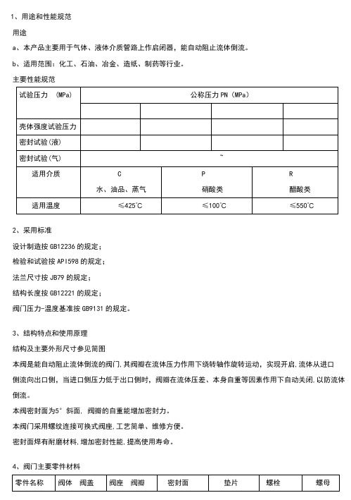
1、用途和性能规范用途a、本产品主要用于气体、液体介质管路上作启闭器,能自动阻止流体倒流。
b、适用范围:化工、石油、冶金、造纸、制药等行业。
主要性能规范2、采用标准设计制造按GB12236的规定;检验和试验按API598的规定;法兰尺寸按JB79的规定;结构长度按GB12221的规定;阀门压力-温度基准按GB9131的规定。
3、结构特点和使用原理结构及主要外形尺寸参见简图本阀是能自动阻止流体倒流的阀门,其阀瓣在流体压力作用下绕转轴作旋转运动,实现开启,流体从进口侧流向出口侧,当进口侧压力低于出口侧时,阀瓣在流体压差、本身自重等因素作用下自动关闭,以防流体倒流。
本阀密封面为5°斜面, 阀瓣的自重能增加密封力。
本阀门采用螺纹连接可换式阀座,工艺简单、维修方便。
密封面焊有耐磨材料,增加密封性能,提高使用寿命。
4、阀门主要零件材料5、保管、安装、使用、检查保管a.本阀须保管存放在干燥、通风的室内。
b.本阀保管存放期闸,阀瓣应处于关闭位置并固定,两端法兰应封闭。
c.本阀存放期间,机加工表面应用容易清除的防锈剂涂覆。
d.长期存放的阀门应定期检查,及时防护。
安装a.本阀安装位置不受限制,通常安装于水平管路,也可以安装于垂直管路或倾斜管路,但要便于检修。
b.安装前,必须仔细核对阀门标志和铭牌是否与工况要求相符。
c.安装时应检查内腔,除去阀瓣固定装置,试转阀瓣检查密封面,并清洗。
d.起吊本阀前,应检查吊环螺钉是否己拧紧。
e.安装本阀时,要特别注意介质流向,应使介质正常流动方向与阀体上箭头指示方向一致,否则会截断介质的正常流向。
f.安装时,应均匀对称拧紧连接螺栓。
使用a.本阀的使用工况必须与铭牌和使用说明书的规定相符。
b.本阀关闭时,会在管路中产生水锤压力,严重时会导致阀门损坏,因此使用者必须定期检查,发现问题及时修理。
检查1.阀门在使用期间应定期检查如下项目发现问题及时修理。
a.紧固件是否出现松动。
b.密封面是否被损坏或严重磨损(停车检修)。
Parker PR系列旋转插值阀手册说明书

Rotary Plug Valves (PR Series)Catalog 4126-PRNovember 1999PR Series Rotary Plug ValvesParker PR Series Plug Valves provide positive leak tight shut-off, high flow capacity, and quick quarter-turn operation in a compact attractive package. The patented blow-out resistant seat design offers reliable sealing technology at all operating pressures. In addition to on-off actuation, the plug design allows forward flow throttling. A selection of valve seat and seal materials may be chosen for media compatibility and performance over a broad range of temperatures. The pressure balanced atmospheric seals are backed by PTFE rings to enhance their performance and increase cycle life.Features• Patented blow-out resistant seat design • Pressures up to 3,000 psig (207 bar) CWP • Quarter-turn operation • Reliable simple design • Straight-through flow• Stainless steel and brass construction• Nitrile, ethylene propylene (EPR and EPDM) and fluorocarbon rubber seats and seals• PTFE back-up rings on atmospheric seals • Low operating torque • Minimum pressure drop • Throttling capability • Positive handle stops• Color coded fracture resistant nylon handles with directional flow indication • Easy to service• 100% factory tested• Options include lock-out devices, downstreamventing, and both stainless steel and T-bar handlesSpecifications• Pressure Ratings:Normal Flow Direction: 3000 psig CWP (207 bar) Reverse Flow Direction: 150 psig (10 bar) Downstream Vent Option: 150 psig (10 bar)Available End ConnectionsOpenClosedZ -Single ferrule CPI ™compression portA -Two ferrule A-LOK ®compression portV -VacuSeal face seal portModel Shown: 4A-PR4-VT-SSM -ANSI/ASME B1.20.1External pipe threads Q -UltraSeal face seal portF -ANSI/ASME B1.20.1Internal pipe threadsU.S. Patent 5,234,193IntroductionFPR Series Rotary Plug ValvesOptionsUsed to lock the handle from accidental rotation in either the opened or closed position. To order the device with the valve, add the suffix –LD to the end of the part number.Example and model shown : 4M-PR4-VT-B-LD. To order the device separately, specify LD-PR4 or LD-PR6.An all metal bar stock design for higher strength and durability. Consists of a stainless steel pin andaluminum adapter. To order, add the suffix –T to the end of the part number. Example and model shown:4M4A-PR4-EPRT-SS-T .Downstream Venting – As the valve is positioned from opened to closed, upstream pressure is released to atmosphere through a vent hole in the body and plug. The maximum recommended operating pressure for this option is 150 psig (10 bar). To order,insert V after PR in the model number. Example: 4A-PR V 4-VT-BColored Handles – Black is the standard color. Add the designator corresponding to the correct handle color as a suffix to the part number: W – white, B – blue, G – green, R – red, Y – yellow. Example: M6A-PR4-BNT-SS-GStainless Steel Directional Handles – A stainless steel handle with the same design configuration as the standard nylon handle is available for the PR4 series. Add the designator –ST as a suffix to the part number. Example: 4Q-PR4-EPDMT-SS-STLock-Out DeviceOffer of SaleThe items described in this document are hereby offered for sale by Parker Hannifin Corporation, its subsidiaries or its authorized distributors. This offer and its acceptance are governed by the provisions stated in the “Offer of Sale” located in Catalog 4103 Instrumentation Valve Technical Guide.© Copyright 1999, Parker Hannifin Corporation. All Rights Reserved.WARNINGFAILURE, IMPROPER SELECTION OR IMPROPER USE OF THE PRODUCTS AND/OR SYSTEMS DESCRIBED HEREIN OR RELATED ITEMS CAN CAUSE DEATH, PERSONAL INJURY AND PROPERTY DAMAGE.This document and other information from Parker Hannifin Corporation, its subsidiaries and authorized distributors provide product and/or system options for further investigation by users having technical expertise. It is important that you analyze all aspects of your application and review the information concerning the product or system in the current product catalog. Due to the variety of operating conditions and applications for these products or systems, the user, through its own analysis and testing, is solely responsible for making the final selection of the products and systems and assuring that all performance, safety and warning requirements of the application are met.The products described herein, including without limitation, product features, specifications, designs, availability and pricing, are subject to change by Parker Hannifin Corporation and its subsidiaries at any time without notice.The correct part number is easily derived from the following number sequence. The six product characteristics required are coded as shown below. *Note: If the inlet and outlet ports are the same, eliminate the outlet port designator.Example:4Z*-PR4-BN T -SS123456Inlet Outlet Valve Seal Back-Up Body PortPortSeriesMaterialRingsMaterialDescribes a PR Series rotary plug valve equipped with 1/4" CPI ™ compression inlet and outlet ports, Buna-N seals, PTFE back-up rings, and stainless steel construction.How to OrderPR Series Rotary Plug Valves8Note: This Pressure versus Temperaturechart reflects the maximum temperature range of indicated body materials.The temperature rating of the elastomer seals become the limiting factor on tem-perature ranges.Temperature Ratings:Buna-N Rubber:-30 °F to 225 °F (-34 °C to 107 °C)Fluorocarbon Rubber:-10 °F to 450 °F (-23 °C to 232 °C)Ethylene Propylene Rubber (EPR): -70 °F to 275 °F (-57 °C to 135 °C)Ethylene Propylene Rubber (EPDM)for steam applications:-70 °F to 275 °F (-57 °C to 135 °C)Note: To determine MPa, multiply bar by 0.1Flow Calculations with 1000 psig (69 bar) Inlet PressurePressure vs. TemperatureKitsPlug Kits – Specify the combination of valve series, seal material, plug material, and handle color (if applicable).Example: KIT-PR4-VT-SS-Y . This kit consists of a PR4 stainless steel plug with fluorocarbon rubber seat and seal elastomers, PTFE back-up rings, yellow handle, and handle pin.Seal Kits – Specify the combination of valve series and seal material. Example: KIT-PR4-BN . This kit consists of a PR4 Buna-N rubber seat and seal elastomers and PTFE back-up rings.*Plugs are PTFE color coated – Stainless steel plugs are black;Brass plugs are green.**Optional Seat and O-ring seal materials are available.Lubrication: Perfluorinated polyetherMaterials of ConstructionModel Shown: 4A-PR4-VT-SSParker Hannifin Corporation Instrumentation Valve Division 2651 Alabama Highway 21 North Jacksonville, AL 36265-9681 Phone: (256) 435-2130Fax: (256) 435-7718。
Belimo LF24-MFT2 通信式旋转阀 Fail-Safe 调节风扇门说明书

LF24-MFT2Communicative rotary actuator fail-safe foradjusting dampers in technical buildinginstallations• Air damper size up to approx. 0.8 m²• Torque motor 4 Nm• Nominal voltage AC/DC 24 V• Control modulating, communicative 2...10 Vvariable• Position feedback 2...10 V variable• Communication via Belimo MP-Bus• Conversion of sensor signalsTechnical dataElectrical data Nominal voltage AC/DC 24 VNominal voltage frequency50/60 HzNominal voltage range AC 19.2...28.8 V / DC 21.6...35.0 VPower consumption in operation 2.5 WPower consumption in rest position 1.2 WPower consumption for wire sizing 5 VAConnection supply / control Cable 1 m, 4x 0.75 mm²Parallel operation Yes (note the performance data) Data bus communication Communicative control MP-BusNumber of nodes MP-Bus max. 8Functional data Torque motor4 NmTorque fail-safe4 NmOperating range Y 2...10 VInput impedance100 kΩOperating range Y variable Start point 0.5...30 VEnd point 2.5...32 VOperating modes optional Open/closePosition feedback U 2...10 VPosition feedback U note Max. 0.5 mAPosition feedback U variable Start point 0.5...8 VEnd point 2.5...10 VPosition accuracy±5%Direction of motion motor selectable with switch L/RDirection of motion variable electronically reversibleDirection of motion fail-safe selectable by mounting L/RManual override NoAngle of rotation Max. 95°Angle of rotation note Adjustable 37...100% with integratedmechanical limitationRunning time motor150 s / 90°Running time motor variable75...300 sRunning time fail-safe<20 s @ -20...50°C / <60 s @ -30°CAdaptation setting range manualAdaptation setting range variable No actionAdaptation when switched onAdaptation after using the rotation switchLF24-MFT2Functional dataOverride controlMAX (maximum position) = 100%MIN (minimum position) = 0%ZS (intermediate position, AC only) = 50%Override control variableMAX = (MIN + 32%)...100%MIN = 0%...(MAX – 32%)ZS = MIN...MAX Sound power level, motor 30 dB(A)Mechanical interface Universal shaft clamp 8...16 mm Position indication MechanicalService lifeMin. 60'000 fail-safe positions Safety dataProtection class IEC/EN III, Safety Extra-Low Voltage (SELV)Degree of protection IEC/EN IP54EMCCE according to 2014/30/EU Low voltage directive CE according to 2014/35/EUCertification IEC/EN IEC/EN 60730-1 and IEC/EN 60730-2-14Hygiene test According to VDI 6022 Part 1 / SWKI VA 104-01, cleanable and disinfectable, low emission Type of actionType 1Rated impulse voltage supply / control 0.8 kV Pollution degree 3Ambient humidity Max. 95% RH, non-condensing Ambient temperature -30...50°C [-22...122°F]Storage temperature -40...80°C [-40...176°F]Servicingmaintenance-free WeightWeight 1.5 kgTechnical data•••••••Safety notesThis device has been designed for use in stationary heating, ventilation and air-conditioning systems and must not be used outside the specified field of application, especially in aircraft or in any other airborne means of transport.Outdoor application: only possible in case that no (sea) water, snow, ice, insolation or aggressive gases interfere directly with the device and that it is ensured that the ambient conditions remain within the thresholds according to the data sheet at any time.Only authorised specialists may carry out installation. All applicable legal or institutional installation regulations must be complied with during installation.The device may only be opened at the manufacturer's site. It does not contain any parts that can be replaced or repaired by the user.Cables must not be removed from the device.To calculate the torque required, the specifications supplied by the damper manufacturers concerning the cross-section and the design, as well as the installation situation and the ventilation conditions must be observed.The device contains electrical and electronic components and must not be disposed of as household refuse. All locally valid regulations and requirements must be observed.LF24-MFT2Mode of operationConverter for sensorsParametrisable actuators Simple direct mounting Adjustable angle of rotation High functional reliabilityHome positionAdaptation and synchronisationProduct featuresConventional operation:The actuator is connected with a standard control signal of 0...10 V and drives to the position defined by the control signal.The actuator moves the damper to the operating position at the same time as tensioning the return spring. The damper is turned back to the fail-safe position by spring force when the supply voltage is interrupted.Operation on Bus:The actuator receives its digital control signal from the higher level controller via the MP-Bus and drives to the position defined. Connection U serves as communication interface and does not supply an analogue measuring voltage.Connection option for a sensor (passive or active sensor or switching contact). The MP actuator serves as an analogue/digital converter for the transmission of the sensor signal via MP-Bus to the higher level system.The factory settings cover the most common applications. Single parameters can be modified with the Belimo service tools MFT-P or ZTH EU.Simple direct mounting on the damper shaft with a universal shaft clamp, supplied with an anti-rotation device to prevent the actuator from rotating.Adjustable angle of rotation with mechanical end stops.The actuator is overload protected, requires no limit switches and automatically stops when the end stop is reached.The first time the supply voltage is switched on, i.e. at the time of commissioning, the actuator carries out a synchronisation. The synchronisation is in the home position (0%).The actuator then moves into the position defined by the control signal.An adaptation can be triggered manually by switching the direction of rotation switch from the left to the right twice within 5s or with the PC-Tool. Both mechanical end stops are detected during the adaptation (entire setting range). Automatic synchronisation after actuating the direction of rotation switch once is programmed. The synchronisation is in the home position (0%).The actuator then moves into the position defined by the control signal.A range of settings can be adapted using the PC-Tool (see MFT-P documentation)AccessoriesGatewaysDescriptionType Gateway MP to BACnet MS/TP UK24BAC Gateway MP to Modbus RTUUK24MOD Electrical accessoriesDescriptionType Auxiliary switch 2x SPDTS2A-F Feedback potentiometer 200 ΩP200A-F Feedback potentiometer 1 kΩP1000A-F Signal converter voltage/current 100 kΩ 4...20 mA, Supply AC/DC 24 V Z-UIC Positioner for wall mounting SGA24Positioner for built-in mounting SGE24Positioner for front-panel mounting SGF24Positioner for wall mountingCRP24-B1MP-Bus power supply for MP actuatorsZN230-24MP Mechanical accessoriesDescriptionType Shaft extension 170 mm ø10 mm for damper shaft ø6...16 mm AV6-20Shaft clamp reversible, clamping range ø16...20 mmK6-1LF24-MFT2DescriptionType Ball joint suitable for damper crank arm KH8 / KH10KG10A Ball joint suitable for damper crank arm KH8KG8Damper crank arm Slot width 8.2 mm, clamping range ø10...18 mm KH8Actuator arm, clamping range ø8...16 mm, Slot width 8.2 mm KH-LF Angle of rotation limiter, with end stop ZDB-LF Form fit adapter 8x8 mmZF8-LF Mounting kit for linkage operation for flat installationZG-LF1Mounting kit for linkage operation for side installation Slot width 6.2 mm ZG-LF3Anti-rotation mechanism 180 mm, Multipack 20 pcs.Z-ARS180L ToolsDescriptionType Service tool, with ZIP-USB function, for parametrisable andcommunicative Belimo actuators, VAV controller and HVAC performance devicesZTH EUBelimo PC-Tool, Software for adjustments and diagnostics MFT-P Adapter for Service-Tool ZTHMFT-C Connecting cable 5 m, A: RJ11 6/4 ZTH EU, B: 6-pin for connection to service socketZK1-GEN Connecting cable 5 m, A: RJ11 6/4 ZTH EU, B: free wire end for connection to MP/PP terminalZK2-GENAccessoriesWire colours:1 = black 2 = red 3 = white 5 = white Electrical installationSupply from isolating transformer.Parallel connection of other actuators possible. Observe the performance data.Wiring diagrams MP-BusAC/DC 24 V, modulatingLF24-MFT2FunctionsFunctions with basic values (conventional mode)Override control with AC 24 V with relay contactsOverride control with AC 24 V with rotary switch Control remotely 0...100% with positioner SG..Minimum limit with positioner SG..Primary/secondary operation (position-dependent)Control with 4...20 mA via external resistorCaution:The operating range must be set to DC 2...10 V.The 500 Ohm resistor converts the 4...20 mA current signal to a voltage signal DC 2...10 V.LF24-MFT2•••••Functions with basic values (conventional mode)Functional checkProcedure1. Connect 24 V to connections 1 and 22. Disconnect connection 3:– With direction of rotation 0: Actuator rotates to the left – With direction of rotation 1: Actuator rotates to the right3. Short-circuit connections 2 and 3:– Actuator runs in opposite direction Functions with specific parameters (Parametrisation necessary)Connection on the MP-BusMP-Bus Network topologyMax. 8 MP-Bus nodesThere are no restrictions for the network topology (star, ring, tree or mixed forms are permitted).Supply and communication in one and the same 3-wire cable • no shielding or twisting necessary• no terminating resistors requiredConnection of active sensorsConnection of external switching contactSupply AC/DC 24 VOutput signal 0...10 V (max. 0...32 V)Resolution 30 mVSwitching current 16 mA @ 24 VStart point of the operating range must be parametrised on the MP actuator as ≥0.5 VLF24-MFT2Functions with specific parameters (Parametrisation necessary)Connection of passive sensors1) Depending on the type 2) Resolution 1 OhmCompensation of the measured value is recommendedOverride control and limiting with AC 24 V with relay contactsControl open/closeOverride control and limiting with AC 24 V with rotary switchControl 3-point with AC 24 VCaution:The "Close" function is only guaranteed if the start point of the operating range is definedas min. 0.5 V.FunctionsLF24-MFT2Operating controls and indicators1MP addressingMove direction of rotation switch in opposite position and backwards (within 4 seconds)Tool connectionServiceThe actuator can be parametrised by ZTH EU via terminal connection.For extended parametrisation the PC tool can be connected.Connection ZTH EU / PC-ToolLF24-MFT2DimensionsSpindle lengthMin. 84Min. 20Clamping rangeFurther documentation• Overview MP Cooperation Partners• Tool connections• Introduction to MP-Bus TechnologyApplication notes• For digital control of actuators in VAV applications patent EP 3163399 must be considered.。
河北运大阀门集团 Z45X-10 16 软密封闸阀 产品说明书
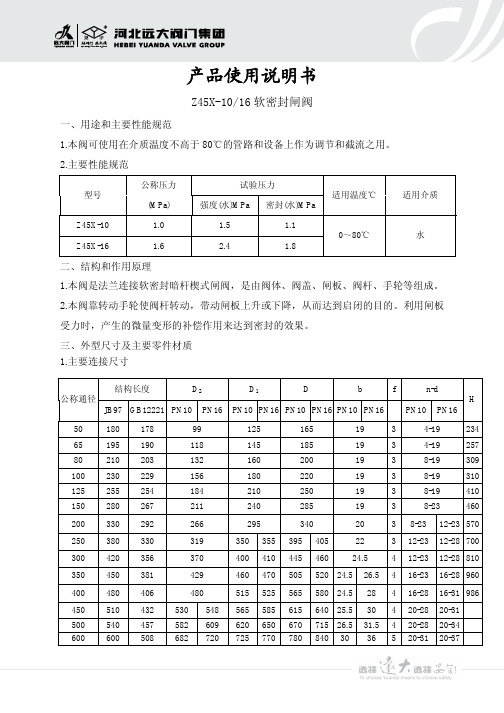
产品使用说明书Z45X-10/16软密封闸阀一、用途和主要性能规范1.本阀可使用在介质温度不高于80℃的管路和设备上作为调节和截流之用。
2.主要性能规范二、结构和作用原理1.本阀是法兰连接软密封暗杆楔式闸阀,是由阀体、阀盖、闸板、阀杆、手轮等组成。
2.本阀靠转动手轮使阀杆转动,带动闸板上升或下降,从而达到启闭的目的。
利用闸板受力时,产生的微量变形的补偿作用来达到密封的效果。
三、外型尺寸及主要零件材质1.主要连接尺寸试验压力型号公称压力(MPa)强度(水)MPa密封(水)MPa适用温度℃适用介质Z45X-10 1.0 1.5 1.1Z45X-161.62.41.80~80℃水结构长度D 2D 1Dbfn-d公称通径JB97GB12221PN10PN16PN10PN16PN10PN16PN10PN16PN10PN16H50180178991251651934-19234651951901181451851934-19257802102031321602001938-193091002302291561802201938-193101252552541842102501938-194101502802672112402851938-234602003302922662953402038-2312-2357025038033031935035539540522312-2312-2870030042035637040041044546024.5412-2312-2881035045038142946047050552024.526.5416-2316-2896040048040648051552556558024.528416-2816-3198645051043253054856558561564025.530420-2820-3150054045758260962065067071526.531.5420-2820-346006005086827207257707808403036520-3120-372.外型及主要零件材质四、保管、安装及使用注意事项1.该阀应放在干燥的仓库内,严禁露天存放。
球阀使用说明书
球阀使用说明书一、产品简介球阀是一种常用于管道系统中的控制元件,它通过球体的旋转来实现对流体的控制。
球阀具有结构简单、使用方便、密封性好、经济实用等特点,广泛应用于石化、冶金、电力、制药等行业。
二、产品特点1. 结构简单:球阀由阀体、球体、阀杆等组成,结构简单紧凑,便于安装和维护。
2. 使用方便:球阀采用旋转操作,开关方便,只需旋动阀杆即可实现快速开启或关闭。
3. 密封性好:球阀采用球体与阀座的配合,密封性好,可保证在高压力下的流体控制。
4. 耐腐蚀性强:球阀材质多样,可根据流体特性选择不同的材质,从而具备较好的耐腐蚀性。
5. 经济实用:球阀的制造工艺简单,成本较低,价格相对较为实惠。
三、使用注意事项1. 安装前检查:在安装球阀之前,应仔细检查阀体、球体、阀杆等部件是否完整,确保无缺损。
检查密封件是否松动或损坏,防止漏气或漏液。
2. 安装位置选择:球阀的安装位置应选择在易于操作的位置,方便开关和维护。
同时,应考虑阀门开启时的流量路径,避免产生任何不必要的压力损失。
3. 密封性检查:球阀关闭后,应通过观察阀杆位置判断是否密封良好。
如果阀杆位置完全收缩,说明密封良好;如果阀杆位置突出,可能存在泄漏问题,需要及时处理。
4. 使用压力:球阀的使用压力范围应符合产品规格要求,过高或过低的压力都可能影响球阀的正常运行。
5. 注意阀门开关:操作球阀时,应缓慢开启或关闭,避免剧烈振动,同时关注阀门的流量变化,确保流体控制的稳定性。
6. 温度范围注意:球阀的材质和密封性能应与流体的温度范围相匹配,避免因温度过高或过低导致球阀损坏或无法工作。
7. 定期维护检修:为保证球阀长期稳定运行,应定期进行维护检修,清除阀体内的杂质,检查密封性能,并涂抹适量的润滑油。
四、故障处理1. 泄漏现象:如果球阀出现泄漏,首先应检查阀体和球体之间的密封性,确认是否需要更换密封件。
如仍然无法解决泄漏问题,应及时联系生产厂家或专业维修人员。
旋塞阀的操作和维护
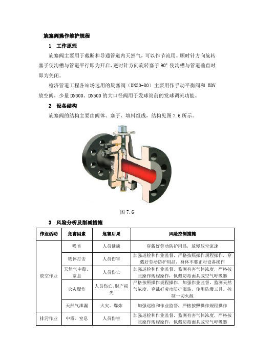
旋塞阀操作维护规程1 工作原理旋塞阀主要用于截断和导通管道内天然气,可以作节流用。
顺时针方向旋转塞子使沟槽与管道平行即为开启,逆时针方向旋转塞子90º使沟槽与管道垂直时即为关闭。
榆济管道工程各站场选用的旋塞阀(DN50-80)主要用作手动平衡阀和BDV 放空阀,少量DN300、DN500的大口径阀用于发球筒前的发球调流功能。
2 设备结构旋塞阀的结构主要由阀体、塞子、填料组成,结构见图7.6所示。
图7.63 风险分析及削减措施作业活动危害因素危害后果风险控制措施放空作业噪音人员健康穿戴好劳动防护用品,放慢放空流速物体打击人员伤害加强巡检和作业监督,严格按照操作规程操作,穿戴好劳动防护用品,身体不要正对设备操作天然气中毒、窒息人员伤亡加强巡检和作业监督,监测有害气体浓度,严格按照操作规程操作,佩戴防毒面具或空气呼吸器火灾爆炸人员伤亡、财产损失严格按照操作规程操作,加强作业监督,监测天然气浓度,穿戴好劳动防护服装,使用防爆工具,控制一切火源天然气泄漏火灾、爆炸加强巡检和作业监督,严格按照操作规程操作排污作业中毒、窒息人员伤害加强巡检和作业监督,监测有害气体浓度,严格按照操作规程操作,佩戴防毒面具或空气呼吸器4 操作方法(1)一般要求1) 操作阀门前应注意检查阀门的开闭标志后再操作。
2) 对于长时间(6个月以上)没有动作和进行清洗、润滑操作的球阀,在操作球阀前应先注入少量清洗液密封脂,以保护阀门密封。
3) 阀门操作完成后必须仔细确认状态,必要时同武汉调控中心共同确认。
(2)手动阀门的操作1) 开阀:逆时针方向转动手轮(或手柄),缓慢打开阀门,根据声音或开度调节流量,全开到位后,回转1/4圈。
2) 关阀:顺时针方向转动手轮(或手柄),缓慢关闭阀门,根据声音或开度调节流量,全关到位后,回转1/4圈。
5 常见故障及处理方法(1)开关操作困难操作困难并非旋塞和阀体配合过紧,而是旋塞表面严重缺少密封脂,导致旋塞表面失去润滑。
Z型说明书(江苏兰阀)

1.概述多回转阀门电动装置,简称为Z 型电装,是阀门实现开启、关闭或调节控制的驱动设备。
Z 型电装适用于闸阀、截止阀、隔膜阀、柱塞阀、节流阀、水闸门等。
可用于明杆阀,也可用于暗杆阀。
本系列电装具有功能全、性能可靠、控制系统先进、体积小、重量轻、使用维护方便等特点。
可对阀门实行远控、集控和自动控制。
广泛用于电力、冶金、石油、化工、造纸、污水处理等行业。
本产品的性能符合JB/T8528-1997 《普通型阀门电动装置技术条件》的规定。
隔爆型的性能符合GB3836.1-2000 《爆炸性气体环境用电气设备第 1 部分:通用要求》,GB3836.2-2000 《爆炸性气体环境用电气设备第 2 部分:隔爆型“d”》及 JB/T8529-1997 《隔爆型阀门电动装置技术条件》的规定。
多回转电动装置按防护类型分:有户外型和隔爆型;按控制方式分:有常规型、整体型和整体调节型;按连接型式分:有转矩型、电站型和推力型。
2.型号表示方法Z—/A :带现场按钮;F:带 4-20mA 信号输出; S:带手动减速箱Z:整体型; T:整体调节型输出轴最大转圈数:阿拉伯数字表示,无数字见表1防护类型: W 表示户外型; B 表示隔爆型输出转速:阿拉伯数字表示,单位r/min (转 /分)连接型式: T 表示推力型, I 表示电站型,无代号为常规转矩型额定输出转矩:阿拉伯数字表示,单位kgf 2 m产品型式:多回转电动装置型号示例:1.Z30I-18W :多回转电动装置,输出转矩300N 2m( 30kgf 2 m),电站型接口,输出转速18r/min ,最大转圈数 60,常规户外型。
2.Z45T-24B/S :多回转电动装置,输出转矩450N2 m( 45kgf2 m),推力型接口,输出转速24 r/min ,最大转圈数 120,隔爆型,带手动减速箱。
3.Z120-24W/240T :多回转电动装置,输出转矩1200N2 m (120kgf 2 m),转矩型接口,输出转速 24 r/min ,最大转圈数 240 圈,整体调节型。
- 1、下载文档前请自行甄别文档内容的完整性,平台不提供额外的编辑、内容补充、找答案等附加服务。
- 2、"仅部分预览"的文档,不可在线预览部分如存在完整性等问题,可反馈申请退款(可完整预览的文档不适用该条件!)。
- 3、如文档侵犯您的权益,请联系客服反馈,我们会尽快为您处理(人工客服工作时间:9:00-18:30)。
济南信赢煤焦化有限公司 150t/h干熄焦工程
旋转密封阀 使用说明书
2006年7月 旋转密封阀 1. 设备概要…………………………………………………………………………1 2. 主要规格…………………………………………………………………………2 3. 各个设备的操作要领…………………………………………………………….3 3.1 旋转密封阀的操作要领
4. 检查、维护………………………………………………………………………..7 4.1 检查、维护 4.2 密封的维护、检查 4.3 转子前端金属的维护、检查 1. 设备概要 本排出装置是设置在冷却室下部、把冷却的焦碳向冷却室外持续地而且是持续保持密封地排出的装置。本排出装置由送料装置的振动给料器和旋转密封阀构成。冷却的焦碳由振动给料器而送到旋转密封阀,通过转子旋转而连续地被送出。被连续定量地送出的焦碳由传送带运送到系统外面。 2. 主要规格 本密封装置是防止CDQ设备的循环气体向系统外泄露的装置。以旋转密封阀的方式进行工作。 表1旋转密封阀主要规格 主要项目 主 要 规 格 转子的外型尺寸 叶片个数 驱动装置 转子转动数 材质 转子密封 衬套 转子叶片前端 Ф1,800х1,428 12个 带有离心减速机的发动机 3.7KWх4Pх460V 5rpm
SS400+S45C WELTEN AR320C SKH55 3. 各机器的操作要领 3.1 旋转密封阀操作要领 由振动给料器送出的焦碳从旋转密封阀上部的装入口投入,由于转子的转动,从下部的排出口被排出。另外,如果固定了转子的转动数,焦碳的送出量的控制可以通过振动给料器来进行。
下面,关于旋转密封阀的各个构成部件的调整方法进行说明。 (1) 缓冲器的调整 煤炭的大块混入焦碳中,在跟旋转密封阀咬住而停止时,为了保护本旋转密封阀,在装入口上部设计安装了缓冲器。它有如下2个特征。 1) 发生万一的时候,尽管煤炭、焦碳互相咬住,但如果是小块的,旋转密封阀可 以压碎这些异物,这时候,没有必要停止机器,可以继续作业。 2) 旋转密封阀咬住煤炭的大块的场合,缓冲器开始作用,吸收转子的转动能以及发动机的驱动能,旋转密封阀停止,这样可以防止转子以及密封的损伤。 缓冲器由四组碟型弹簧构成,每组的弹簧特性如图4所示。在出厂时弹簧的初期扭矩尽管设定为200kg/组,但是根据调整螺栓可以对其进行任意设定调整。 图4 Shock Absorber 弹簧特性(1组) (2) 转子前端金属 转子叶片与外盒之间的间隙会影响到密封性能,考虑到叶片前端应有一定的耐磨耗性能,采用了SKH55的材料制作。应定期地对叶片前端的磨耗、破损情况进行检查。 (3) 密封弹簧环的调整 本旋转密封阀为了发挥高密封性能,在端面上设计了密封环,防止转子侧面发生漏气。密封环如图6显示的那样,为了适应褶皱面的磨耗以及转子、外盒间的热膨胀差,使用了弹簧的设计,使密封环能够随时紧密地压在外盒的端面上。弹簧的特性如图5显示。
每组的压接力设定为大约8.5kg。
(4) 带有离心减速器的电机 本旋转密封阀如果在规格处理范围内运转,回转数可以固定操控在5.0rpm,与工作效率相适应,没有进行改变的必要。 本电机可以手动操作,详细的内容,可以参照附加的离心减速器操作说明书。 (5) 缓冲器继电器的调整 本旋转密封阀在咬住70tх300以上的煤炭等非常坚硬的异物,导致转子停止时,用缓冲器继电器可以进行检测出来,便于振动加料器以及旋转密封阀及时停止。
图7 咬住异物转子停止时的检测方法 缓冲器继电器的各种设定值如表6所示。 表2 缓冲器继电器的各种设定值(参考值) 开始时间(秒) 缓冲时间(秒) 负荷电流(%) 1调整范围 0.2---2.0 0.2---3 30---130 2允许调整范围 ---- 2以下 100---130 3设定值 5 2 100 4. 检查、维护 4.1 检查、维护 排出装置的维护、检查项目以及进行的周期如表3所示。另外,在图11、12里,显示了平面给料器外盒以及旋转密封阀的检查。
表3排出装置的维护、检查项目 序号 机器名称 维护、检查项目 周 期 参 考 1 振动给料器相关部件 软管的损伤 各部管线的磨耗 灰尘的附着、堆积状态 1回/定期维修 1回/定期维修
关于振动给料器本身的详细说明参照机器使用说明书。 2 旋转密封阀 前部金属安装螺栓的拧紧情况 侧面底部的排出孔 转子叶片前端以及安装螺栓的磨耗 密封环的磨耗 各部管线的磨耗 缓冲器的磨耗 安装后 1个月 1回/定期维修 1回/定期维修 1回/定期维修 安装后 1个月 1回/年修
关于电机、缓冲器的本身的详细说明参照机器使用说明书。 图11振动给料器外盒的检查口 4.2 密封环的维护、检查 (1) 侧面密封部位的作用
图13 侧面密封的构造 1) 侧面密封在冷间和热间中,具有防止从转子侧面漏气的功能。在热间,由于外盒和汽缸的轴方向热膨胀差不同,在工作台上,在密封环和外盒衬垫之间就会产生间隙。因此,为了确保密封性能,把密封环用弹簧压在外盒衬垫上,消除密封环和汽缸之间产生的间隙。其调整可以通过弹簧啮合力和托架啮合力来进行。
转子热膨胀图14热间膨胀时 图15向密封环的拧紧力 (2)密封环调整要领 1) 压盖密封、保护环的组合要领 压盖密封、保护环的组合时,为了防止内漏和外漏,在结合部位和沟槽部位应填加硅系列密封材料(三合粘着剂1212#)。另外,为了防止堆积灰尘,压盖密封、保护环的组合部位应位于转子叶片之间。
图16密封、保护环的组合 2) 密封环的组合要领 事前,把油脂涂在密封环A、B上,(涂的时候,要求A面厚,B面薄)然后,在转子的侧面,再涂上为了防止积灰用的三合粘着剂(THREE BOND)1212#。组合时,要求把密封环的结合部位位于转子叶片之间。而且,为了使密封环的结合部位不至于和保护环的结合部位处于同一位置,请务必按照要求把密封环的结合部位位于转子叶片之间。
图17密封环的组合 3) 弹簧和托架的调整要领 把接缝调整在2mm,把托架安装上。然后,把调整用螺帽拧紧,直到托架间的尺寸达到7mm为止。
图18密封环的啮合力的调整 4) 密封环的啮合力的调整要领 a) 密封环、外盒衬垫之间的间隙检 查把0.05标准间隙量具插入密封环 和外盒衬垫之间,确认有无间隙。
b)托架拧紧状况的检查 只把一个密封环完 全从托架取下,把托 架顶着密封环的端面 ,按照下列标准,来 判断托架的拧紧状 况。
图20拧紧情况确认 c)弹簧强度的检查 在密封环的加工孔上安装了六角螺栓,在手上稍加牵引,就可以将其取下。向密封环一侧衬垫进行压挤,确认间隙为0。(如同检查步骤(a)中的方法)在密封环不能恢复时,请再一次进行调整。
5) 再调整方法 在上述检查里,调整不良的场合,请进行如下的调整。 (a)接缝调整 在检查步骤(b)里,托架和密封环之间是否有间隙呢?重叠程度如果在0.3mm以上的场合,应调整接缝,直到把重叠程度调整到0.1mm为止。 (b)调整用螺帽的调整 接缝调整后,进行上述检查步骤(c)的检查,尽管如此,密封环也还可能有不能恢复的场合,为了增加弹簧的强度,应进一步拧紧调整用螺帽。 (c)在密封环达到可以自如地被弹簧弹回的状态后,密封环的密封面间隙应进一步用标准量具进行调整,直到达到0.5mm为止。 (3)试漏要领(工程内试行运转时) 密封环的调整结束后,在侧面密封部位进行试漏,进行调整状态是否良好的最后确认。 1) 试漏要领 (a)在RSV投入口以及下部斜槽上安装盲板。 (b)把RSV侧面的扇型检查口打开以后,向下部斜槽送 压缩空气。 (c)手动旋转RSV驱动用电机,在RSV侧面的检查口检查侧面密封部位的密封情况。 (d)如果有空气泄露剧烈的地方,应进行如下调整。 a)在从密封环接口部位泄露激烈的地方,请进一步填充三合粘着剂#1212。 b)在从密封环褶皱面泄露激烈的地方,应遵循上述调整要领,再度进行调整。 4.3 转子前端金属的维护、检查 (1)转子前端金属的作用 1)转子前端在旋转密封阀上,为了减少从转子叶片和外盒内面的间隙泄露气体的量,应尽量缩小其间隙。 2) 转子前端的金属采用了装配螺栓的构造,通过螺栓位置设置的微调整,把间隙固定在基准范围内。 3) 转子前端的金属附近通常气体流速较快,考虑到除尘等,其材质应是耐磨耗的,我们选用了SKH55(高速工具用钢材) (2) 转子前端的金属调整要领 1) 工厂内的调整要领 (a)对于测定位置D,对于所有的转子叶片,都应进行调整,使间隙达到2mm。 (b)间隙的测定位置如下图所示,应在中央、左右共计3处进行。 (c)然后,在测定位置图25A、B、C、D4处,分别测定关于转子叶片的上述3处的间隙。 (d)以在(c)项中测定得到的数据为基础,对各个前端的金属位置进行微调整,使各位置的间隙达到2.0±0.5mm。
2) 现场的调整要领 转子前端的金属和外盒内面衬垫之间的间隙很窄,允许范围只能在2.0±0.5mm之间,如果间隙的调整情况不良,在热间作业时,就可能会出现间隙消失、产生磨损等的危险。所以,基本的原则是不进行现场的调整。因此,在由于漏气量增加等原因,不能充分发挥旋转密封阀的机能时,应考虑在工厂内把转子前端的金属和外盒内面衬垫取下,更换事先准备好的旋转密封阀备件。 但是,转子前端的金属破损的原因有多种, 进行更换时,应考虑如下几个方面。 (a) 在现场的转子前端金属更换事先准备 a) 停止循环风机,确认炉内压力已经消失。 b) 关闭维护用的滑门,把震动加料器和旋转密封阀内的焦碳全部排除到系统外面。 c) 确认在RSV排出部位以及传送带上是否积尘。 d) 打开外盒检查口,切实地进行漏气检查。