High-Speed Internet Switches and Routers
莫稳网EDS-518E系列18口高速 managed Ethernet 交换机说明书

EDS-518E Series14+4G-port Gigabit managed EthernetswitchesFeatures and Benefits•4Gigabit plus14fast Ethernet ports for copper and fiber•Turbo Ring and Turbo Chain(recovery time<20ms@250switches),1RSTP/ STP,and MSTP for network redundancy•RADIUS,TACACS+,MAB Authentication,SNMPv3,IEEE802.1X,MAC ACL, HTTPS,SSH,and sticky MAC-addresses to enhance network security •Security features based on IEC62443•EtherNet/IP,PROFINET,and Modbus TCP protocols supported for device management and monitoring•Fiber Check™—comprehensive fiber status monitoring and warning on MST/ MSC/SSC/SFP fiber ports•Supports MXstudio for easy,visualized industrial network management•V-ON™ensures millisecond-level multicast data and video network recoveryCertificationsIntroductionThe EDS-518E standalone,compact18-port managed Ethernet switches have4combo Gigabit ports with built-in RJ45or SFP slots for Gigabit fiber-optic communication.The14fast Ethernet ports have a variety of copper and fiber port combinations that give the EDS-518E Series greater flexibility for designing your network and application.The Ethernet redundancy technologies Turbo Ring,Turbo Chain,RSTP/STP,and MSTP increase the system reliability and availability of your network backbone.The EDS-518E also supports advanced management and security features.In addition,the EDS-518E Series is designed specifically for harsh industrial environments with limited installation space and high protection level requirements,such as maritime,rail wayside,oil and gas,factory automation,and process automation.Additional Features and Benefits•DHCP Option82for IP address assignment with different policies•Supports EtherNet/IP,PROFINET,and Modbus TCP protocols fordevice management and monitoring•IGMP snooping and GMRP for filtering multicast traffic•Port-based VLAN,IEEE802.1Q VLAN,and GVRP to ease networkplanning•QoS(IEEE802.1p/1Q and TOS/DiffServ)to increase determinism•Port Trunking for optimum bandwidth utilization•Port mirroring for online debugging•Automatic warning by exception through email and relay output•SNMPv1/v2c/v3for different levels of network management•RMON for proactive and efficient network monitoring•Fiber Check™provides a comprehensive fiber Digital DiagnosticMonitoring(DDM)function and event warning on MST/MSC/SSC/SFPfiber ports•Bandwidth management to prevent unpredictable network status•Lock port function for blocking unauthorized access based on MACaddress•Supports the ABC-02-USB(Automatic Backup Configurator)forsystem configuration backup/restore and firmware upgrade SpecificationsInput/Output InterfaceAlarm Contact Channels1,Relay output with current carrying capacity of1A@24VDCButtons Reset buttonDigital Input Channels1Digital Inputs+13to+30V for state1-30to+3V for state0Max.input current:8mA1.Gigabit Ethernet recovery time<50msEthernet Interface10/100BaseT(X)Ports(RJ45connector)EDS-518E-4GTXSFP:14EDS-518E-MM-SC-4GTXSFP/MM-ST-4GTXSFP/SS-SC-4GTXSFP:12All models support:Auto negotiation speedFull/Half duplex modeAuto MDI/MDI-X connectionCombo Ports(10/100/1000BaseT(X)or100/1000BaseSFP+)410/100/1000BaseT(X)Ports(RJ45connector)Auto negotiation speedFull/Half duplex modeAuto MDI/MDI-X connection100BaseFX Ports(multi-mode SC connector)EDS-518E-MM-SC-4GTXSFP Series:2100BaseFX Ports(multi-mode ST connector)EDS-518E-MM-ST-4GTXSFP Series:2100BaseFX Ports(single-mode SC connector)EDS-518E-SS-SC-4GTXSFP Series:2Optical Fiber800Typical Distance4km5km40kmWavelength Typical(nm)13001310TX Range(nm)1260to13601280to1340 RX Range(nm)1100to16001100to1600Optical Power TX Range(dBm)-10to-200to-5 RX Range(dBm)-3to-32-3to-34 Link Budget(dB)1229 Dispersion Penalty(dB)31Note:When connecting a single-mode fiber transceiver,we recommend using anattenuator to prevent damage caused by excessive optical power.Note:Compute the“typical distance”of a specific fiber transceiver as follows:Linkbudget(dB)>dispersion penalty(dB)+total link loss(dB).Standards IEEE802.3for10BaseTIEEE802.3u for100BaseT(X)and100BaseFXIEEE802.3ab for1000BaseT(X)IEEE802.3z for1000BaseSX/LX/LHX/ZXIEEE802.3x for flow controlIEEE802.1D-2004for Spanning Tree ProtocolIEEE802.1w for Rapid Spanning Tree ProtocolIEEE802.1s for Multiple Spanning Tree ProtocolIEEE802.1p for Class of ServiceIEEE802.1Q for VLAN TaggingIEEE802.1X for authenticationIEEE802.3ad for Port Trunk with LACPEthernet Software FeaturesFilter802.1Q VLAN,Port-based VLAN,GVRP,IGMP v1/v2/v3,GMRPIndustrial Protocols EtherNet/IP,Modbus TCP,PROFINET IO Device(Slave)Management LLDP,Back Pressure Flow Control,BOOTP,Port Mirror,DHCP Option66/67/82,DHCPServer/Client,Fiber check,Flow control,IPv4/IPv6,RARP,RMON,SMTP,SNMP Inform,SNMPv1/v2c/v3,Syslog,Telnet,TFTPMIB Ethernet-like MIB,MIB-II,Bridge MIB,P-BRIDGE MIB,Q-BRIDGE MIB,RMON MIBGroups1,2,3,9,RSTP MIBRedundancy Protocols Link Aggregation,MSTP,RSTP,STP,Turbo Chain,Turbo Ring v1/v2Security Broadcast storm protection,HTTPS/SSL,TACACS+,SNMPv3,MAB authentication,Sticky MAC,NTP authentication,MAC ACL,Port Lock,RADIUS,SSH,SMTP with TLS Time Management NTP Server/Client,SNTPSwitch PropertiesIGMP Groups2048MAC Table Size16KMax.No.of VLANs64Packet Buffer Size1MbitsPriority Queues4VLAN ID Range VID1to4094USB InterfaceStorage Port USB Type ALED InterfaceLED Indicators PWR1,PWR2,STATE,FAULT,10/100M(TP port),100M(fiber port),Gigabit combo port,MSTR/HEAD,CPLR/TAILSerial InterfaceConsole Port USB-serial console(Type B connector)DIP Switch ConfigurationDIP Switches Turbo Ring,Master,Coupler,ReservePower ParametersConnection2removable4-contact terminal block(s)Input Current EDS-518E-4GTXSFP Series:0.37A@24VDCEDS-518E-MM-SC-4GTXSFP/MM-ST-4GTXSFP/SS-SC-4GTXSFP:0.41A@24VDC Input Voltage12/24/48/-48VDC,Redundant dual inputsOperating Voltage9.6to60VDCOverload Current Protection SupportedReverse Polarity Protection SupportedPhysical CharacteristicsHousing MetalIP Rating IP30Dimensions94x135x137mm(3.7x5.31x5.39in)Weight1518g(3.35lb)Installation DIN-rail mounting,Wall mounting(with optional kit) Environmental LimitsOperating Temperature Standard Models:-10to60°C(14to140°F)Wide Temp.Models:-40to75°C(-40to167°F) Storage Temperature(package included)-40to85°C(-40to185°F)Ambient Relative Humidity5to95%(non-condensing)Standards and CertificationsSafety UL508,EN60950-1(LVD)EMC EN61000-6-2/-6-4EMI CISPR32,FCC Part15B Class AEMS IEC61000-4-2ESD:Contact:8kV;Air:15kVIEC61000-4-3RS:80MHz to1GHz:10V/mIEC61000-4-4EFT:Power:4kV;Signal:4kVIEC61000-4-5Surge:Power:4kV;Signal:4kVIEC61000-4-6CS:10VIEC61000-4-8PFMFHazardous Locations ATEX,Class I Division2Maritime DNV-GL,LR,ABS,NKPower Substation IEC61850-3,IEEE1613Railway EN50121-4Traffic Control NEMA TS2Shock IEC60068-2-27Freefall IEC60068-2-32Vibration IEC60068-2-6MTBFTime723,953hrsStandards Telcordia(Bellcore),GBWarrantyWarranty Period5yearsDetails See /warrantyPackage ContentsDevice1x EDS-518E Series switchCable1x USB type A male to USB type B male Installation Kit4x cap,plastic,for RJ45port4x cap,plastic,for SFP slotDocumentation1x quick installation guide1x warranty card1x product certificates of quality inspection,Simplified Chinese1x product notice,Simplified ChineseNote SFP modules need to be purchased separately for use with this product.DimensionsOrdering InformationModel Name 10/100BaseT(X)PortsRJ45ConnectorCombo Ports10/100/1000BaseT(X)or100/1000BaseSFP+100BaseFX PortsMulti-Mode,SCConnector100BaseFX PortsMulti-Mode,STConnector100BaseFX PortsSingle-Mode,SCConnectorOperating Temp.EDS-518E-4GTXSFP144–––-10to60°C EDS-518E-4GTXSFP-T144–––-40to75°C EDS-518E-MM-SC-4GTXSFP1242––-10to60°CEDS-518E-MM-SC-4GTXSFP-T1242––-40to75°CEDS-518E-MM-ST-4GTXSFP124–2–-10to60°CEDS-518E-MM-ST-4GTXSFP-T124–2–-40to75°CEDS-518E-SS-SC-4GTXSFP124––2-10to60°CEDS-518E-SS-SC-4GTXSFP-T124––2-40to75°C Accessories(sold separately)Storage KitsABC-02-USB Configuration backup and restoration tool,firmware upgrade,and log file storage tool for managedEthernet switches and routers,0to60°C operating temperatureABC-02-USB-T Configuration backup and restoration tool,firmware upgrade,and log file storage tool for managedEthernet switches and routers,-40to75°C operating temperatureSFP ModulesSFP-1FELLC-T SFP module with1100Base single-mode with LC connector for80km transmission,-40to85°Coperating temperatureSFP-1FEMLC-T SFP module with1100Base multi-mode with LC connector for4km transmission,-40to85°Coperating temperatureSFP-1FESLC-T SFP module with1100Base single-mode with LC connector for40km transmission,-40to85°Coperating temperatureSFP-1G10ALC WDM-type(BiDi)SFP module with11000BaseSFP port with LC connector for10km transmission;TX1310nm,RX1550nm,0to60°C operating temperatureSFP-1G10ALC-T WDM-type(BiDi)SFP module with11000BaseSFP port with LC connector for10km transmission;TX1310nm,RX1550nm,-40to85°C operating temperatureSFP-1G10BLC WDM-type(BiDi)SFP module with11000BaseSFP port with LC connector for10km transmission;TX1550nm,RX1310nm,0to60°C operating temperatureSFP-1G10BLC-T WDM-type(BiDi)SFP module with11000BaseSFP port with LC connector for10km transmission;TX1550nm,RX1310nm,-40to85°C operating temperatureSFP-1G20ALC WDM-type(BiDi)SFP module with11000BaseSFP port with LC connector for20km transmission;TX1310nm,RX1550nm,0to60°C operating temperatureSFP-1G20ALC-T WDM-type(BiDi)SFP module with11000BaseSFP port with LC connector for20km transmission;TX1310nm,RX1550nm,-40to85°C operating temperatureSFP-1G20BLC WDM-type(BiDi)SFP module with11000BaseSFP port with LC connector for20km transmission;TX1550nm,RX1310nm,0to60°C operating temperatureSFP-1G20BLC-T WDM-type(BiDi)SFP module with11000BaseSFP port with LC connector for20km transmission;TX1550nm,RX1310nm,-40to85°C operating temperatureSFP-1G40ALC WDM-type(BiDi)SFP module with11000BaseSFP port with LC connector for40km transmission;TX1310nm,RX1550nm,0to60°C operating temperatureSFP-1G40ALC-T WDM-type(BiDi)SFP module with11000BaseSFP port with LC connector for40km transmission;TX1310nm,RX1550nm,-40to85°C operating temperatureSFP-1G40BLC WDM-type(BiDi)SFP module with11000BaseSFP port with LC connector for40km transmission;TX1550nm,RX1310nm,0to60°C operating temperatureSFP-1G40BLC-T WDM-type(BiDi)SFP module with11000BaseSFP port with LC connector for40km transmission;TX1550nm,RX1310nm,-40to85°C operating temperatureSFP-1GEZXLC SFP module with11000BaseEZX port with LC connector for110km transmission,0to60°C operatingtemperatureSFP-1GEZXLC-120SFP module with11000BaseEZX port with LC connector for120km transmission,0to60°C operatingtemperatureSFP-1GLHLC SFP module with11000BaseLH port with LC connector for30km transmission,0to60°C operatingtemperatureSFP-1GLHLC-T SFP module with11000BaseLH port with LC connector for30km transmission,-40to85°C operatingtemperatureSFP-1GLHXLC SFP module with11000BaseLHX port with LC connector for40km transmission,0to60°C operatingtemperatureSFP-1GLHXLC-T SFP module with11000BaseLHX port with LC connector for40km transmission,-40to85°Coperating temperatureSFP-1GLSXLC SFP module with11000BaseLSX port with LC connector for500m transmission,0to60°C operatingtemperatureSFP-1GLSXLC-T SFP module with11000BaseLSX port with LC connector for500m transmission,-40to85°Coperating temperatureSFP-1GLXLC SFP module with11000BaseLX port with LC connector for10km transmission,0to60°C operatingtemperatureSFP-1GLXLC-T SFP module with11000BaseLX port with LC connector for10km transmission,-40to85°C operatingtemperatureSFP-1GSXLC SFP module with11000BaseSX port with LC connector for300/550m transmission,0to60°Coperating temperatureSFP-1GSXLC-T SFP module with11000BaseSX port with LC connector for300/550m transmission,-40to85°Coperating temperatureSFP-1GZXLC SFP module with11000BaseZX port with LC connector for80km transmission,0to60°C operatingtemperatureSFP-1GZXLC-T SFP module with11000BaseZX port with LC connector for80km transmission,-40to85°C operatingtemperatureWall-Mounting KitsWK-51-01Wall-mounting kit,2plates,6screws,51.6x67x2mmSoftwareMXview-50Industrial network management software with a license for50nodes(by IP address)MXview-100Industrial network management software with a license for100nodes(by IP address)MXview-250Industrial network management software with a license for250nodes(by IP address)MXview-500Industrial network management software with a license for500nodes(by IP address)MXview-1000Industrial network management software with a license for1000nodes(by IP address)MXview-2000Industrial network management software with a license for2000nodes(by IP address)MXview Upgrade-50License expansion of MXview industrial network management software by50nodes(by IP address)©Moxa Inc.All rights reserved.Updated Aug06,2019.This document and any portion thereof may not be reproduced or used in any manner whatsoever without the express written permission of Moxa Inc.Product specifications subject to change without notice.Visit our website for the most up-to-date product information.。
ZL60301中文资料_数据手册_IC数据表

• Link reach 300-m with 50/125 µm 500 MHz. km fiber at 2.5 Gbps
• Channel BER better than 10-12
• Industry standard MPO/MTP ribbon fiber connector interface
Reliability assurance is based on Telcordia GR-468-CORE and the parts are compliant to the EU directive 2002/95/EC issued 27 January 2003 [RoHS].
Exemption 6 & 7
The module is fitted with two pluggable industry-standard connectors. For the electrical interface, a 100 position FCI MegArray® receptacle is used. For the optical interface, an industry-standard MTPTM(MPO) connector is used, which is compliant with IEC 61754-7. This provides ease of assembly on the host board and enables provisioning of bandwidth on demand.
Shortform Data Sheet
March 2007
Ordering Information
ZL60301MLDC Transceiver ZL60301MMDC Transceiver with EMI-clip
介绍华为的英语作文

介绍华为的英语作文Huawei is a leading global provider of information and communications technology (ICT) infrastructure and smart devices. Founded in 1987, the company is headquartered in Shenzhen, China, and has grown to become one of the world's largest telecommunications equipment manufacturers.The company's mission is to bring digital to every person, home, and organization for a fully connected, intelligent world. Huawei invests heavily in research and development, focusing on innovation in next-generation networks, cloud computing, artificial intelligence, and more.Huawei's product and service portfolio is extensive, ranging from smartphones and tablets to routers and switches. They also offer a variety of enterprise solutions, including cloud services and data center infrastructure.One of the key factors contributing to Huawei's success isits commitment to customer-centric innovation. The company has a global network of research and development centers and collaborates with leading academic institutions and industry partners to drive technological advancements.Despite facing challenges and competition in the global market, Huawei continues to push the boundaries of technology and strives to deliver high-quality products and services to its customers worldwide.In conclusion, Huawei is a company that has made significant contributions to the ICT industry and is dedicated to shaping the future of digital communication. Its innovative spirit and customer-focused approach have positioned it as a key player in the global technology landscape.。
PreSonus StudioLive 网络控制参考手册说明书

Networking for StudioLive ™ Mixers Remote Control Reference Manual ®UC Surface QMix-UC Studio One1 Introduction — 11.1 What You Will Need — 11.2 Additional Resources — 12 Networking Basics — 32.1 Routers and Switches — 33 Adding a Computer — 53.1 Wired Control — 53.2 Wireless Control — 64 Adding a Tablet — 74.1 Connecting Your iPad to Your Network — 7 4.2 Connecting Your Android Tabletto Your Network — 85 Adding a Mobile Device — 95.1 Connecting Your iPhone/iPod touchto Your Network — 95.2 Connecting Your Android Phoneto Your Network — 101StudioLive Series III and AI-series mixers can be directly connected to astandard LAN network, so that they can be remotely controlled using UCSurface or QMix-UC. StudioLive Series III mixers can also be networkedto your Mac® or Windows® computer to control Studio One Artist.This guide will direct you through the best practices in establishing a stablecontrol network for your StudioLive mixer as well as some networkingbasics to make you more comfortable troubleshooting any issues thatmay arise. Companion guides cover the functions of UC Surface, QMix-UC,and Studio One DAW Control Mode for StudioLive Series III mixers.Note: While this guide discusses networking terminology andbest practices, PreSonus can only provide support for networkingissues that directly relate to PreSonus hardware only.1.1 What You Will NeedIn addition to your StudioLive mixer, you will need the following tonetwork your mixer and use the companion software accessories:Wireless RouterA wireless router is required to remote control your StudioLive mixerusing UC Surface or QMix-UC for iOS® or Android™. This device allowsdata to flow between your mixer, tablet, mobile device, and computerwith a single Ethernet cable (more on that in Section 2.1).Ethernet CableYour mixer requires a hardwired connection to your Wireless Router. This can beacquired at most electronics dealers.Tablet or Touch-equipped Computer (recommended for UC Surface)PreSonus® UC Surface provides all the controls you need to mix a show withoutbeing tied to your mixer’s hardware surface. It is designed to run on both AppleiPad® and Android™ tablets. Because it also runs on Windows, you can use aWindows Surface or Touch-equipped laptop to remotely control your mixer.Mobile Device (required for QMix-UC)QMix-UC provides performers with wireless control over their monitor(aux) mixes onstage and in the recording studio from their mobile devices.It is designed to run on both iOS and Android mobile devices.1.2 Additional ResourcesThis guide covers proper networking procedures for control only.Additional reference guides are available for the following:Hardware Guides:•StudioLive Series III Console Mixer Owner’s Manual. Use this referenceguide to understand all the hardware functions on your StudioLiveSeries III console mixer (StudioLive 64S, StudioLive 32S, StudioLive 32SX,StudioLive 32SC, StudioLive 32, StudioLive 24, StudioLive 16).•StudioLive Series III Rackmount Mixer Owner’s Manual. Use this referenceguide to understand all the hardware functions on your StudioLive SeriesIII rackmount mixer (StudioLive 32R, StudioLive 24R, StudioLive 16R).•StudioLive AI-Series Console Mixer Owner’s Manual. Use this referenceguide to understand all the hardware functions on your StudioLive AI-Seriesconsole mixer (StudioLive 32.4.2AI, StudioLive 24.4.2AI, StudioLive 16.4.2AI).•StudioLive AI-Series Rackmount Mixer Owner’s Manual. Use this referenceguide to understand all the hardware functions on your StudioLive AI-Series rackmount mixer (StudioLive RM/RML32, StudioLive RM/RML16).Software Guides:•Capture 3 Reference Manual. Included with StudioLive mixersis Capture, a digital-audio multitrack-recording applicationdesigned to make recording quick and easy.•QMix-UC Reference Manual. This guide describes the features and functionsof QMix-UC with every StudioLive mixer model. QMix-UC lets up to 16 usersremotely control the Aux Mixes on your StudioLive using their smartphone.•Studio One Integration Reference Manual. Studio One Artistis included with every StudioLive mixer. In addition to being apowerful DAW, Studio One provides unique routing and integrationfeatures. This manual will help you get the most from your StudioLivemixer when used with Studio One or Studio One Artist.•UC Surface Reference Manual. This guide describes the features andfunctions of UC Surface with every StudioLive mixer model. UC Surfacecan be used to remotely control ever function on your StudioLivemixer or specific functions, depending on the set permissions, orto turn your tablet into additional screens for your mixer.•Using Your StudioLive as an Audio Interface with UniversalControl Reference Guide. This guide describes the features andfunctions Universal Control as well as how to use your StudioLivemixer as an audio interface with your favorite DAW application. Additional Resources:•StudioLive Series III AVB Networking Guide. This manual covers advancedAVB audio networking configuration for the StudioLive Series III mixers.•StudioLive Series III Stage box Mode Addendum. The StudioLiveSeries III rackmount mixers (StudioLive 32R, StudioLive 24R, StudioLive16R) can be used as advanced stageboxes for StudioLive Series IIIconsole mixers (StudioLive 32, StudioLive 24, StudioLive 16).•StudioLive Series III Studio One DAW Control Addendum. StudioLiveSeries III console mixers (StudioLive 32, StudioLive 24, StudioLive16) can be used to control Studio One and Studio One Artist.2 At its core, a network is created when two or more devices (computers, iPads, Android devices, networkable mixers) intelligently share data between one another. In the case of the StudioLive mixers and their companion software, this is control data. A network can be as simple as a single StudioLive mixer connected to an iPad via a wireless router.The type of network employed by StudioLive mixers is called a Local Area Network or LAN. This type of network is formed by devices within a reasonably close proximity to one another (i.e., same house, same office, or same campus).Please note: that while some of the information in this section applies to standard LAN networks that do not include a StudioLive mixer, this section describes requirements and best practices regarding configuring a control network for your StudioLive mixer only.Below are some common terms you may encounter when purchasing and configuring your control network:•Node. A node is any device connected to a network. This could be a computer, an iOS or Android device, your mixer, etc.•Segment. This is any part of the network that is separated from other parts of the network by a router, switch, or bridge.•Topology. The topology describes the way in which each node connects to the network. •Media Access Control (MAC) Address. This is the physical address of any node on the network. This string of numbers identified the manufacturer and the serial number of each node’s Network Interface Card or NIC.2.1 Routers and SwitchesWhen connecting multiple nodes a standard LAN network, you can usually choose to use either a hub, a switch, a router, or some combination thereof. For StudioLive control networks, you must use a router. If your router has an integrated switch and you require additional Ethernet ports, you can connect a switch to your router, more on that in a minute.The most common form of routers on the market today are wireless. While there are such devices as wired routers, they are not very common. PreSonus requires a high-quality wireless router to use mobile devices and tablets, however, you also have the option of connecting your computer wirelessly for both UC Surface use and Studio One control if you would prefer this method over hardwiring your computer to your router.Let’s take a look at the following simple network:In this example, we have a StudioLive 32SC, an Android tablet, and an iPhone all communicating with one another through a wireless router with an integrated switch. The StudioLive 32SC is connected to the wireless router via its Control port using an Ethernet LAN connection on theintegrated switch. The tablet and the iPhone are connected wirelessly.While you’d never notice this empirically, the router is communicating toeach device one at a time in small data packets. It takes the data packet fromthe Source Address and sends it to the Destination Address. These addressesare derived from the Internet Protocol (IP) Addresses of each device on the network. In most cases, these IP Addresses are assigned dynamically by the router using the DHCP protocol, however most devices, including the StudioLive mixers support Static Self-Assigned and Manual addressing. Please review the Universal Control and UC Surface Reference Guide for more information.The router’s job is to keep track of these data packets androute them to and from the appropriate IP address.By contrast, a network switch acts as a controller so that informationflows more efficiently between devices on a network. In the simplestterms, a switch creates a network and routers act as the dispatcher,selecting the best path for the information to travel.Power User Tip: When connecting your mixer to your router, you may find both LAN and WAN ports. WAN ports are sometimes labeled ‘Internet’. This port is firewalled and designed to communicate with Internet Service Providers (ISPs). PreSonus recommends only using the LAN ports on your router.3 There are three great reasons to network your computer to your StudioLive mixer:•UC Surface. UC Surface can be used as a second screen for your mixer, you can also back-up and organize scenes and presets. •Capture. When the computer running Capture is networked to your StudioLive, you can save and recall your StudioLive mix scenes with your Capture audio as well as remote control your mixer’s digital returns for Virtual Soundcheck.•Studio One. Networking your StudioLive Series III console mixer to Studio One allows you to use it as a control surface. Additional integration features are also available. Please review the Studio One StudioLive Integration Reference Guide for more information .3.1 Wired ControlHardwiring both your mixer and your computer to the same router is the easiest configuration:Connect standard CAT5e or CAT6 Ethernet cables from your computer’s Ethernet port to LAN port on an Ethernet router, and from the router tothe Control port on the StudioLive’s rear panel as depicted above.To verify proper connectivity, launch Universal Control and verifythat your StudioLive mixer appears in the device list.NOTE: UCNET doesn’t support dual network connections. If your computer is hardwired to the same router as your mixer, you must disable its wireless connection (if applicable).3.2 Wireless ControlUsing a wireless router allows you to remote control your mixer without any additional cabling.Connect your mixer and your computer to your router as shown above. Make sure you are connecting the Control port of your mixer to a LAN port on your router. To connect your computer wirelessly to your router:Windows 7+1. Click on the network icon in the notification area to open the Connect to Network Control Panel.2. Select the name of the wireless network you set for your wireless router.3. Enter the password.4. Click Connect.macOS 10.8 and later1. On the Menu bar click on the Wireless Status icon.2. Select the name of the wireless network you set for your wireless router.3. Enter the password.4. Click JoinPower User Tip: In some cases, your router is too far from your mixer and your computer to connect them both. This is where Access Points can come in handy. These devices allowyou to extend your wireless network and provide additional connectivity.4 4.1 Connecting Your iPad to Your Network1. Tap on the Settings icon in your iPad.2. Tap on “Wi-Fi.”3. Select the network to which your StudioLive is connected and enter the password when prompted. Tap Join.4.Enter the password when prompted and tap Join.4.2 Connecting Your Android Tablet to Your Network1. Tap on the System Settings icon.2. Tap on “Wi-Fi.”3. Select the network to which your StudioLive is connectedand enter the password when prompted. Tap Join.4. Enter the password when prompted and tap Join5 5.1 Connecting Your iPhone/iPod touch to Your Network1. Tap on the Settings icon in your iPhone/iPod touch.2. Tap on “Wi-Fi” making sure it is set to “On.”3. Under “Choose a Network,” select the same network you saved on your StudioLive from the list.4.Tap on the network to select it.5. Enter the password when prompted and tap Join.Important: You must connect your computer and iOS devices tothe same network as your StudioLive mixer each time you planon remote-controlling your StudioLive with UC Surface,or QMix-UC.5.2 Connecting Your Android Phone to Your Network1. Tap on the System Settings icon.2. Tap on “Wi-Fi.”3. Select the network to which your StudioLive is connectedand enter the password when prompted. Tap Join.4. Enter the password when prompted and tap JoinDinner is Served Added bonus: PreSonus’ previously Top Secret recipe for…Redfish CouvillionIngredients:•¼ C Vegetable oil•¼ C flour• 1 onion diced• 1 clove garlic minced• 1 green pepper diced• 3 celery stalks diced• 1 14oz can diced tomatoes• 1 bottle light beer• 2 bay leaves• 1 tsp thyme• 2 lbs Redfish filletsCooking Instructions:1. In a heavy saucepan or large skillet, heat oil on medium high and slowly add flour a tablespoon at a time to create a roux.Continue cooking the roux until it begins to brown, creating a dark blond roux.2. Add garlic, onions, green pepper, and celery to roux.3. Sauté vegetables for 3-5 minutes until they start to soften.4. Add tomatoes, bay leaves, thyme, and redfish. Cook for several minutes.5. Slowly add beer and bring to a low boil.6. Reduce heat and simmer uncovered for 30-45 minutes until redfish and vegetables are completely cooked, stirring occa-sionally. Break up redfish into bite size chunks and stir in. Add pepper or hot sauce to taste. Do not cover.7. Serve over riceServes 6-8While not one of Southeast Louisiana’s more famous dishes, Redfish Couvillion is a favorite way to serve our favorite Gulf fish. Also known as Reds or Red Drum, Redfish is not only fun to catch, it’s also delicious!©2021 PreSonus Audio Electronics, Inc. All Rights Reserved. AudioBox USB, Capture, CoActual, EarMix, Eris, FaderPort, FireStudio, MixVerb, Notion, PreSonus, PreSonus AudioBox, QMix, RedLightDist,SampleOne, Sceptre, StudioLive, Temblor, Tricomp, WorxAudio, and the Wave Logo are registered trademarks of PreSonus Audio Electronics, Inc. Studio One is a registered trademark of PreSonusSoftware Ltd.Mac, macOS, iOS, and iPadOS are registered trademarks of Apple, Inc., in the U.S. and other countries. Windows is a registered trademark of Microsoft, Inc., in the U.S. and other countries.ASIO is a trademark and software of Steinberg Media Technologies GmbH. VST is a trademark of Steinberg Media Technologies GmbH.Other product names mentioned herein may be trademarks of their respective companies. All specifications subject to change without notice... except the recipe, which is a classic.Networking for StudioLive™Mixers Remote Control Reference ManualUC Surface QMix-UC Studio OneBaton Rouge • USAPart# 70-62000082-B。
莫萨IKS-G6824A系列24G端口层3全GigabitManaged以太网交换机特性与优势说明书
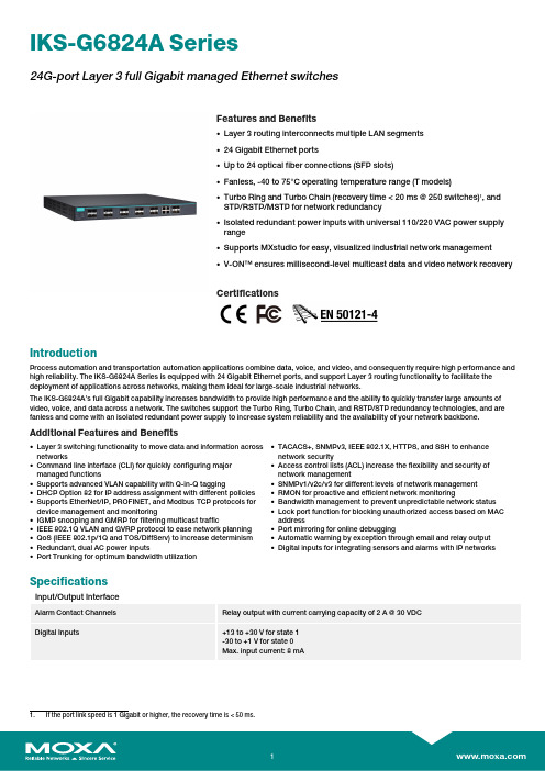
IKS-G6824A Series24G-port Layer 3full Gigabit managed EthernetswitchesFeatures and Benefits•Layer 3routing interconnects multiple LAN segments•24Gigabit Ethernet ports•Up to 24optical fiber connections (SFP slots)•Fanless,-40to 75°C operating temperature range (T models)•Turbo Ring and Turbo Chain (recovery time <20ms @250switches)1,andSTP/RSTP/MSTP for network redundancy•Isolated redundant power inputs with universal 110/220VAC power supplyrange•Supports MXstudio for easy,visualized industrial network management•V-ON™ensures millisecond-level multicast data and video network recoveryCertificationsIntroductionProcess automation and transportation automation applications combine data,voice,and video,and consequently require high performance and high reliability.The IKS-G6824A Series is equipped with 24Gigabit Ethernet ports,and support Layer 3routing functionality to facilitate the deployment of applications across networks,making them ideal for large-scale industrial networks.The IKS-G6824A’s full Gigabit capability increases bandwidth to provide high performance and the ability to quickly transfer large amounts of video,voice,and data across a network.The switches support the Turbo Ring,Turbo Chain,and RSTP/STP redundancy technologies,and are fanless and come with an isolated redundant power supply to increase system reliability and the availability of your network backbone.Additional Features and Benefits•Layer 3switching functionality to move data and information acrossnetworks•Command line interface (CLI)for quickly configuring majormanaged functions•Supports advanced VLAN capability with Q-in-Q tagging•DHCP Option 82for IP address assignment with different policies•Supports EtherNet/IP,PROFINET,and Modbus TCP protocols fordevice management and monitoring•IGMP snooping and GMRP for filtering multicast traffic•IEEE 802.1Q VLAN and GVRP protocol to ease network planning•QoS (IEEE 802.1p/1Q and TOS/DiffServ)to increase determinism•Redundant,dual AC power inputs•Port Trunking for optimum bandwidth utilization •TACACS+,SNMPv3,IEEE 802.1X,HTTPS,and SSH to enhance network security •Access control lists (ACL)increase the flexibility and security of network management •SNMPv1/v2c/v3for different levels of network management •RMON for proactive and efficient network monitoring •Bandwidth management to prevent unpredictable network status •Lock port function for blocking unauthorized access based on MAC address •Port mirroring for online debugging •Automatic warning by exception through email and relay output •Digital inputs for integrating sensors and alarms with IP networksSpecificationsInput/Output InterfaceAlarm Contact ChannelsRelay output with current carrying capacity of 2A @30VDC Digital Inputs +13to +30V for state 1-30to +1V for state 0Max.input current:8mA1.If the port link speed is 1Gigabit or higher,the recovery time is <50ms.Ethernet Interface10/100/1000BaseT(X)Ports(RJ45connector)IKS-G6824A-4GTXSFP-HV-HV Series:20IKS-G6824A-8GSFP-4GTXSFP-HV-HV Series:12 100/1000BaseSFP Ports IKS-G6824A-8GSFP-4GTXSFP-HV-HV Series:8IKS-G6824A-20GSFP-4GTXSFP-HV-HV Series:204Combo Ports(10/100/1000BaseT(X)or100/1000BaseSFP+)Standards IEEE802.1D-2004for Spanning Tree ProtocolIEEE802.1p for Class of ServiceIEEE802.1Q for VLAN TaggingIEEE802.1s for Multiple Spanning Tree ProtocolIEEE802.1w for Rapid Spanning Tree ProtocolIEEE802.1X for authenticationIEEE802.3for10BaseTIEEE802.3ab for1000BaseT(X)IEEE802.3ad for Port Trunk with LACPIEEE802.3u for100BaseT(X)and100BaseFXIEEE802.3x for flow controlIEEE802.3z for1000BaseSX/LX/LHX/ZX Ethernet Software FeaturesManagement ARPBack Pressure Flow ControlBOOTPDDMDHCP Option66/67/82DHCP Server/ClientFlow controlIPv4LLDPPort MirrorRARPRMONSCPSMTPSNMP InformSNMPv1/v2c/v3SyslogTelnetTFTPFilter802.1QBPDU FilterBPDU GuardGMRPGVRPIGMP v1/v2/v3QinQ VLANMulticast Routing DVMRPPIM-DMPIM-SMPIM-SSMRedundancy Protocols Link AggregationMRPMSTPRSTPTurbo ChainTurbo Ring v1/v2V-ONRouting Redundancy VRRPSecurity Access control listBroadcast storm protectionHTTPS/SSLMAB authenticationSticky MACNTP authenticationPort LockRADIUSSSHTACACS+Time Management NTP Server/ClientSNTPUnicast Routing OSPFRIPV1/V2Static RouteIndustrial Protocols EtherNet/IPModbus TCPPROFINETMIB Bridge MIBEthernet-like MIBMIB-IIP-BRIDGE MIBQ-BRIDGE MIBRMON MIB Groups1,2,3,9RSTP MIBSwitch PropertiesDRAM128MBFlash16MBIGMP Groups4096Jumbo Frame Size9.6KBMAC Table Size16KMax.No.of VLANs256Packet Buffer Size12MbitsVLAN ID Range VID1to4094Priority Queues8USB InterfaceStorage Port USB Type ASerial InterfaceConsole Port USB-serial console(Type B connector) Power ParametersInput Voltage110to240VACRedundant dual inputsOperating Voltage85to264VACInput Current Max.0.66A@110VACMax.0.39A@220VACPower Consumption Max.37.83W@110VACMax.40.15W@220VACOverload Current Protection SupportedReverse Polarity Protection SupportedPhysical CharacteristicsIP Rating IP30Dimensions440x44x386.9mm(17.32x1.73x15.23in)Weight5100g(11.25lb)Installation Rack mountingEnvironmental LimitsOperating Temperature Standard Models:-10to60°C(14to140°F)Wide Temp.Models:-40to75°C(-40to167°F)Storage Temperature(package included)-40to75°C(-40to167°F)Ambient Relative Humidity5to95%(non-condensing)Standards and CertificationsSafety UL62368-1IEC62368-1UL61010-2-201EN61010-2-201EMC EN55032/24EMI CISPR32,FCC Part15B Class AEMS IEC61000-4-2ESD:Contact:4kV;Air:8kVIEC61000-4-3RS:80MHz to1GHz:10V/mIEC61000-4-4EFT:Power:2kV;Signal:1kVIEC61000-4-5Surge:Power:2kV;Signal:1kVIEC61000-4-6CS:10VIEC61000-4-8PFMFRailway EN50121-4Freefall IEC60068-2-32Shock IEC60068-2-27Vibration IEC60068-2-6MTBFTime IKS-G6824A-4GTXSFP-HV-HV Series:697,302hrsIKS-G6824A-8GSFP-4GTXSFP-HV-HV Series:648,494hrsIKS-G6824A-20GSFP-4GTXSFP-HV-HV Series:670,194hrsStandards Telcordia(Bellcore),GBWarrantyWarranty Period5yearsDetails See /warrantyPackage ContentsDevice1x IKS-G6824A Series switchCable1x USB type A male to USB type B maleInstallation Kit2x rack-mounting ear8x cap,plastic,for SFP slot(IKS-G6824A-4GTXSFP-HV-HV Series)16x cap,plastic,for SFP slot(IKS-G6824A-8GSFP-4GTXSFP-HV-HV Series)28x cap,plastic,for SFP slot(IKS-G6824A-20GSFP-4GTXSFP-HV-HV Series) Power Supply1x power cord,EU type1x power cord,US typeDocumentation1x quick installation guide1x warranty cardNote SFP modules need to be purchased separately for use with this product. DimensionsOrdering InformationModel Name LayerCombo Ports10/100/1000BaseT(X)or100/1000BaseSFP+100/1000Base SFPSlots10/100/1000BaseT(X)PortsRJ45ConnectorOperating Temp.IKS-G6824A-4GTXSFP-HV-HV34020-10to60°CIKS-G6824A-8GSFP-4GTXSFP-HV-HV34812-10to60°CIKS-G6824A-20GSFP-4GTXSFP-HV-HV34200-10to60°CIKS-G6824A-4GTXSFP-HV-HV-T34020-40to75°CIKS-G6824A-8GSFP-4GTXSFP-HV-HV-T34812-40to75°CIKS-G6824A-20GSFP-4GTXSFP-HV-HV-T34200-40to75°C Accessories(sold separately)Storage KitsABC-02-USB Configuration backup and restoration tool,firmware upgrade,and log file storage tool for managedEthernet switches and routers,0to60°C operating temperatureSFP ModulesSFP-1FELLC-T SFP module with1100Base single-mode with LC connector for80km transmission,-40to85°Coperating temperatureSFP-1FEMLC-T SFP module with1100Base multi-mode,LC connector for2/4km transmission,-40to85°C operatingtemperatureSFP-1FESLC-T SFP module with1100Base single-mode with LC connector for40km transmission,-40to85°Coperating temperatureSFP-1G10ALC WDM-type(BiDi)SFP module with11000BaseSFP port with LC connector for10km transmission;TX1310nm,RX1550nm,0to60°C operating temperatureSFP-1G10ALC-T WDM-type(BiDi)SFP module with11000BaseSFP port with LC connector for10km transmission;TX1310nm,RX1550nm,-40to85°C operating temperatureSFP-1G10BLC WDM-type(BiDi)SFP module with11000BaseSFP port with LC connector for10km transmission;TX1550nm,RX1310nm,0to60°C operating temperatureSFP-1G10BLC-T WDM-type(BiDi)SFP module with11000BaseSFP port with LC connector for10km transmission;TX1550nm,RX1310nm,-40to85°C operating temperatureSFP-1G20ALC WDM-type(BiDi)SFP module with11000BaseSFP port with LC connector for20km transmission;TX1310nm,RX1550nm,0to60°C operating temperatureSFP-1G20ALC-T WDM-type(BiDi)SFP module with11000BaseSFP port with LC connector for20km transmission;TX1310nm,RX1550nm,-40to85°C operating temperatureSFP-1G20BLC WDM-type(BiDi)SFP module with11000BaseSFP port with LC connector for20km transmission;TX1550nm,RX1310nm,0to60°C operating temperatureSFP-1G20BLC-T WDM-type(BiDi)SFP module with11000BaseSFP port with LC connector for20km transmission;TX1550nm,RX1310nm,-40to85°C operating temperatureSFP-1G40ALC WDM-type(BiDi)SFP module with11000BaseSFP port with LC connector for40km transmission;TX1310nm,RX1550nm,0to60°C operating temperatureSFP-1G40ALC-T WDM-type(BiDi)SFP module with11000BaseSFP port with LC connector for40km transmission;TX1310nm,RX1550nm,-40to85°C operating temperatureSFP-1G40BLC WDM-type(BiDi)SFP module with11000BaseSFP port with LC connector for40km transmission;TX1550nm,RX1310nm,0to60°C operating temperatureSFP-1G40BLC-T WDM-type(BiDi)SFP module with11000BaseSFP port with LC connector for40km transmission;TX1550nm,RX1310nm,-40to85°C operating temperatureSFP-1GEZXLC SFP module with11000BaseEZX port with LC connector for110km transmission,0to60°C operatingtemperatureSFP-1GEZXLC-120SFP module with11000BaseEZX port with LC connector for120km transmission,0to60°C operatingtemperatureSFP-1GLHLC SFP module with11000BaseLH port with LC connector for30km transmission,0to60°C operatingtemperatureSFP-1GLHLC-T SFP module with11000BaseLH port with LC connector for30km transmission,-40to85°C operatingtemperatureSFP-1GLHXLC SFP module with11000BaseLHX port with LC connector for40km transmission,0to60°C operatingtemperatureSFP-1GLHXLC-T SFP module with11000BaseLHX port with LC connector for40km transmission,-40to85°Coperating temperatureSFP-1GLSXLC SFP module with11000BaseLSX port with LC connector for1km/2km transmission,0to60°Coperating temperatureSFP-1GLSXLC-T SFP module with11000BaseLSX port with LC connector for1km/2km transmission,-40to85°Coperating temperatureSFP-1GLXLC SFP module with11000BaseLX port with LC connector for10km transmission,0to60°C operatingtemperatureSFP-1GLXLC-T SFP module with11000BaseLX port with LC connector for10km transmission,-40to85°C operatingtemperatureSFP-1GSXLC SFP module with11000BaseSX port with LC connector for300m/550m transmission,0to60°Coperating temperatureSFP-1GSXLC-T SFP module with11000BaseSX port with LC connector for300m/550m transmission,-40to85°Coperating temperatureSFP-1GZXLC SFP module with11000BaseZX port with LC connector for80km transmission,0to60°C operatingtemperatureSFP-1GZXLC-T SFP module with11000BaseZX port with LC connector for80km transmission,-40to85°C operatingtemperatureSFP-1GTXRJ45-T SFP module with11000BaseT port with RJ45connector for100m transmission,-40to75°C operatingtemperaturePower CordsPWC-C7AU-2B-183Power cord with Australian(AU)plug,2.5A/250V,1.83mPWC-C13AU-3B-183Power cord with Australian(AU)plug,1.83mPWC-C7EU-2B-183Power cord with Continental Europe(EU)plug,2.5A/250V,1.83mPWC-C13CN-3B-183Power cord with three-prong China(CN)plug,1.83mPWC-C13US-3B-183Power cord with United States(US)plug,1.83mPWC-C13UK-3B-183Power cord with United Kingdom(UK)plug,1.83mPWC-C7US-2B-183Power cord with United States(US)plug,10A/125V,1.83mPWC-C13EU-3B-183Power cord with Continental Europe(EU)plug,1.83mPWC-C7UK-2B-183Power cord with United Kingdom(UK)plug,2.5A/250V,1.83mSoftwareMXview-50Industrial network management software with a license for50nodes(by IP address)MXview-100Industrial network management software with a license for100nodes(by IP address)MXview-250Industrial network management software with a license for250nodes(by IP address)MXview-500Industrial network management software with a license for500nodes(by IP address)MXview-1000Industrial network management software with a license for1000nodes(by IP address)MXview-2000Industrial network management software with a license for2000nodes(by IP address)MXview Upgrade-50License expansion of MXview industrial network management software by50nodes(by IP address)©Moxa Inc.All rights reserved.Updated Aug28,2023.This document and any portion thereof may not be reproduced or used in any manner whatsoever without the express written permission of Moxa Inc.Product specifications subject to change without notice.Visit our website for the most up-to-date product information.。
信息系统安全漏洞评估及管理制度

信息系统安全漏洞评估及管理制度___的子公司___发布了《信息系统安全漏洞评估及管理制度》。
该制度的目的是为了评估和管理信息系统安全漏洞,以确保公司的信息系统安全。
本文将对该制度进行概述。
1.概述信息系统安全漏洞评估及管理制度》是为了保障公司信息系统安全而制定的管理文件。
该制度对信息系统安全漏洞的评估和管理进行规范,旨在确保公司信息系统的安全性。
2.正文术语定义:本制度中所使用的术语,包括“信息系统安全漏洞”、“安全漏洞生命周期”等,均按照国际通用的定义进行解释。
职责分工:制度中明确了各部门的职责分工,包括信息安全部门、技术部门和管理部门等。
他们各自负责信息系统安全漏洞的评估和管理工作。
安全漏洞生命周期:本制度规定了安全漏洞的生命周期,包括漏洞的发现、评估、修复和验证等环节。
在每个环节中,相关部门都要按照规定的流程进行操作,以确保漏洞得到妥善处理。
此外,本制度还规定了信息系统安全漏洞评估和管理的具体操作流程,包括漏洞的识别、分类、评估、修复和验证等步骤。
这些步骤的执行将有助于提高公司信息系统的安全性,保护公司的信息资产。
信息安全漏洞管理是企业信息安全管理中非常重要的一环。
通过对信息系统的漏洞进行评估、分析和整改,可以有效地降低信息安全风险,保障企业信息资产的安全性和完整性。
在进行信息安全漏洞管理时,需要遵循以下几个原则:全面性、实效性、透明度和可追溯性。
全面性指对企业信息系统中的所有漏洞进行评估和整改;实效性指整改措施必须具有实际效果;透明度指漏洞管理的过程和结果应该对内部人员和外部监管机构公开透明;可追溯性指漏洞管理的每个环节都需要有明确的记录和跟踪。
对信息系统中的漏洞进行评估时,需要对漏洞的风险等级进行评估。
风险等级的高低取决于漏洞的危害程度和可能性。
对于高风险等级的漏洞,需要采取及时有效的整改措施,以避免对企业信息资产造成不可挽回的损失。
评估范围是信息安全漏洞管理的重要组成部分。
评估范围应该包括企业信息系统中的所有关键节点和敏感信息,以确保漏洞管理的全面性和有效性。
Allied Telesis 光纤转换器产品说明书
Connectivity GuideProduct Catalog | 1Allied Telesis2 |ETHERNET AND FAST ETHERNET STANDALONE MEDIA CONVERTERSMC13MC101XLMC102XLMC103XLMC103LHMC104XLMC115XLMC116XL10T 100TX 100TX 100TX 100FX MMF (SC)10T or 100TX 10T or 100TX Allied Telesis media converters enable the connection of disparate cabling types in networks where many cabling types exist. Network segments may also operate at different speeds, and media converters can be used to convert between speeds. Typically, media converters are used to connect copper and fiber-optic cabling that coexist in a network. Converters exist in a variety of standalone, multi-port, and modular forms. These different physical forms address the need for different applications and conversion densities.MMCThe Allied Telesis MMC Series of FastEthernet mini media converters leverages its smaller size to not only help the environment with a small carbon footprint, but also to save space in its working environment. Despite its compact size, the MMC Series delivers all the power and functionality of standard size media converters.PoEAllied Telesis PC PoE Series switches are the ideal solution for powering remote devices such as IP phones, video cameras, wireless access points, etc., which are more than 100 m from a Power over Ethernet switch.Desktop PoweredThe Allied Telesis DMC1000 Series of Gigabit mini media converters are among the smallest media converters in the market today. At just 1.25 in wide x 3.6 in deep x 0.85 in high, these media converters can easily fit into the palm of your hand. In addition to being compact — with a small carbon footprint — the DMC1000 Series can also be powered with the included micro USB to USB cable, and plugged directly into a laptop or PC. This saves installation time and cabling as there are no further power requirements necessary.Allied Telesis media converters extend network distances by adding fiber and VDSL (via coax and telephone-grade twisted pair) onlywhere it is needed. This enables customers to keep pace with changing technology and to integrate high-bandwidth devices into the network without changing the entire network infrastructure. From standalone units to chassis-based blades, Allied Telesis media converters are highly configurable to meet every need.Media ConvertersStandaloneFAST ETHERNET AND GIGABIT ETHERNET STANDALONE MINI MEDIA CONVERTERS10/100TX10/100TX10/100/1000T100FX (LC)100FX (SC)1000SX (LC)MMF MMF MMF100FX100FX1000SX1310 nm850 nmMMC200/LC MMC200/SC MMC2000/LCGIGABIT ETHERNET STANDALONE MEDIA CONVERTERSMC1004MC1008/SP1000T1000T1000SX (SC)SFP* Dependant on SFPMedia Converters | 3Allied Telesis4|Desktop PoweredUniversal Power SupplyFor customers already using Allied Telesis media converters, replacement power adapters are available.▶MCPWRUniversal, high-efficiency external power adapterFAST ETHERNET AND GIGABIT DESKTOP USB POWEREDMissingLinkThe Allied Telesis MissingLink ™feature enables media converters to pass the link status of their connections and therebytrigger corrective action when a problem on a link is detected.For example, if the twisted-pair cable to the 10/100TX port on an Allied Telesismedia converter were to fail, the unit would respond by dropping the link on the 100FX fiber-optic port.Most managed devices, such as switches and routers, can be configured to take a specific recovery action in the event of the loss of connection on a port. In some cases, the unit can be configured to seek a redundant path to a disconnected end-node or send out a trap to a network management station, and so alert the network administrator of the problem.Smart MissingLinkThe Allied Telesis Smart MissingLink ™feature has identical operation to MissingLink, with an added link failure alert system. If any of the media converter ports fail, the link LED will begin to flash. This aids with diagnostics, allowing network administrators to more quickly locate and rectify the fault.Smart Link RestorationSmart Link restoration allows the devices, in the cases of power failure, link loss or other interrupted service, to automatically restore the link without the need to restart/reset them.RedundancyIn many cases, Allied Telesis media converters are critical components in a network, carrying data between sites over long distances. It is imperative that all efforts are taken to ensure reliability of the network, and thus a network design with redundancy is mandatory. The components most likely to fail are the power supplies. The majority of Allied Telesis media converters can be deployed with hot-swappable, hot-removable power supplies to ensure maximum uptime.DMC1000/SCDMC1000/STSUPERSPEED USB 3.1/USB-C TO FIBER MEDIA CONVERTERSUSB 3.1/USB-C UMC200/STUMC2000/LCGIGABIT ETHERNET STANDALONE MEDIA CONVERTERS FAST ETHERNET STANDALONEPC2000/LC PC2002POE10/100/1000T10/100/1000T1000SX (LC)SFPLC1000SXPoE & IndustrialIndustrialAllied Telesis industrial Ethernet media converters offer an operating range from -40° to 75°C.The temperature-hardened IMC Series features Plug-and-Play and auto-negotiation.PoE* Dependant on SFP Allied Telesis PC PoE Series switches are the ideal solution for powering remote devices such as IP phones,Media Converters | 5Allied Telesis6|DesktopAll Allied Telesis media converters have the option to be fitted with rubber feet. These allow the product to be positioned on the desktop.WallA standalone media converter or switch can be easily mounted on a wall or under a table using this wallmount fixture. ▶WLMTWallmount fixture (supplied in packages of 10)DIN RailThis universal bracket allows a wide range of Allied Telesis media converters and media/rate converters to be mounted onto an industry-standard 35 mm DIN rail. ▶DINRAIL1-010Mounting kit (supplied in packages of 10)Mounting HardwareThe majority of unmanaged Allied Telesis MC, GS, and FS Series media converters can be mounted in anumber of ways.RackLarger multi-channel and modular mediaconverters ship with 19" rackmount kits. Smaller media converters may also be rackmounted in a number of ways:▶MCR1 chassisThis small chassis can berackmounted, and allows a single standalone media converter or 2-port switch to be powered by an internal power supply. It is available with either AC or -48vDC power supply.▶MCR12 chassisThis chassis allows mounting of up to 12 standalone media converters orswitches. The chassis supports optional redundant power supplies and can be AC or DC powered. ▶TRAY1 andTRAY4These simple trays allow one to four standalone media converters to be mounted into a rack.MMC Rack▶MMCR18This chassis allows mounting of up to 18 standalone MMC Series mediaconverters. The chassis supports optional redundant power supplies and can be AC or DC powered. Standard, 19-inch, rack.Product Catalog | 7FAST ETHERNET FIBER GIGABIT FIBER2814FX2874SXExpressCard/34 (54 compatible)ExpressCard/34 (54 compatible)SCSC■■■Preboot Execution Environment (PXE) SupportPXE allows network administrators to perform prebootprocedures on a system, such as installing an operating system,running a virus checker, or downloading a predefined systemconfiguration. PXE support included in Allied Telesis adaptercards allows a workstation or computer to boot from a remoteserver connected to the network prior to booting from the localhard drive.8 |Allied TelesisAdapter Cards | 9Jumbo Frames SupportNormal Ethernet packets are limited to a maximum size of 1548 bytes. Received packets larger than this are normally rejected by the interface card as errors. Jumbo frames support is beneficial for sending large packets, especially when the data contained in these packets either has a time-critical element, or is so large that the time taken to send multiple smaller packets is too great. Jumbo frame packets are normally up to 9000 bytes long.Long-Distance FiberWith the introduction of single-mode fiber adapters, Allied Telesis has extended the size of a fiber network from up to two kilometers over multi-mode fiber, to up to 20 km for Fast Ethernet, and 10 km forGigabit Ethernet.Advanced Power Management (ACPI)ACPI is part of the environmental control initiative for computers. Allied Telesis adapter cards support ACPI, which places the system in a low power state when it is not receiving or transmitting data.GIGABIT FIBER2916SX2916LX102914SX/LC2914SX/SC2914SPPCI (32-bit)PCI (32-bit)PCIe (x1)PCIe (x1)PCIe (x1)SFP SC, LC LC LC SC SFPMMF SMF MMF MMF10/100 SFP220 m / 500 m10 km220 m / 500 m220 m / 500 m Depends on SFP ■■■■Allied Telesis 10 |Wake-on-LAN (WoL)WoL is a feature of adapter cards that allows a computer fitted witha card to be remotely powered-on. The computer receives a specialdata packet via the network port that will cause the computer to boot.This, coupled with PXE support, allows network administrators to gaincomplete access to all computers on their networks.Adapter Cards | 11Network VirtualizationAllied Telesis server adapter cards are specifically designed for use in a virtualized environment. The cards interact directly with the virtualization hypervisor software, offloading many of the interface tasks from the main CPU, thus increasing the overall performance of the virtual machine.The ANC10S Series 10 Gigabit adaptercard improves performance with next-generation technology — VMware, DataCenter Bridging, Direct Path, NetQueue— that includes features such as loopback(inter-VM communication), priority-weightedbandwidth management, and doubling thenumber of data queues per port from fourto eight. Also supported are multicast andbroadcast data on a virtualized server.Superior FunctionalityThe ANC10S Series includes dedicatedhardware and processors to process framesat the highest levels for both transmit andreceive paths in the operating system —advantageous for virtualization applications.The ANC10S Series enables convergenceof all networked communications possiblein a server, such as data (LAN), storagenetworks (iSCSI), and clustering.Allied Telesis 12 |Product Catalog | 13Allied Telesis14 |FAST ETHERNET FIBER TRANSCEIVERSSPFX/2SPFXBD-LC-13SPFXBD-LC-15SPFX/15SFP SFP SFP SFP MMF SMF SMFSMF 2 (Rx, Tx) 1 (BiDi) 1 (BiDi) 2 (Rx, Tx)100Mbps 100Mbps 100Mbps 100MbpsGIGABIT FIBER TRANSCEIVERSSPSXSPSX/ISPEXSPLX10SPLX10/ISFP SFP SFP SFP SFP MMF MMF MMF SMF SMF 2 (Rx, Tx) 2 (Rx, Tx) 2 (Rx, Tx)1000Mbps 1000MbpsQSFP+ Cables ▶QSFP1CUQSFP+ 1 m cable▶QSFP3CU QSFP+ 3 m cableOptical Cables ▶MTP12-1MTP cable for QSFP+ Series, 1 m▶MTP12-5MTP cable for QSFP+ Series, 5 mBreakout Cables▶QSFP-4SFP10G-3CUQSFP+ port to 4 × 10G ports, 3 m▶QSFP-4SFP10G-5CUQSFP+ port to 4 × 10G ports, 5 mTransceivers | 15SFP+SFP+TwinaxTwinax 10G10GSP10 Series (SFP+)The SP10 Series offers customers a wide variety of 10 Gigabit Ethernet connectivity options for data center, enterprise, and service provider transport applications. These hot-swappable devices plug into an Ethernet SFP+ port and have the smallest 10G form factor in the industry. Configurations can be optimized to meet a variety of distance and service requirements.COPPER RJ-45 TRANSCEIVERS SPTXSFP 10/100/1000T 100 m RJ-450°C to 70°CSP10TW1SP10TW3GIGABIT FIBER TRANSCEIVERSSFP SFP SFP SFP SMF SMF SMF SMF 1 (BiDi) 1 (BiDi) 2 (Rx, Tx) 2 (Rx, Tx)1000Mbps1000MbpsSPBD10-13SPBD10-14SPLX40SPZX80Allied Telesis16 |Network Service Provider Transceiversi MG Transceivers▶TN-P015-ASC, Gigabit/100M, 20 km SFP, Tx 1310, Rx 1480 - 1560, use with iMG1400 Series ▶SPBD20EPON-13/I20 km, bi-directional, 1 Gigabit GEPON SFP for iMG2426FMODEL GIGABIT OPTICS (NSP)FEATURESSPBD20-13/ISPBD20-14/ISPBD40-13/ISPBD40-14/IFORM FACTOR SFP SFP SFP SFP FIBER TYPE SMF SMF SMF SMF NUMBER OF FIBERS 1 (BiDi) 1 (BiDi) 1 (BiDi) 1 (BiDi)SPEED 1000Mbps1000Mbps1000Mbps1000MbpsDDM■■■■Rx WAVELENGTH 1550 nm 1310 nm 1490 nm 1310 nm Tx WAVELENGTH 1310 nm 1490 nm 1310 nm 1490 nm MAX DISTANCE 20 km 20 km 40 km 40 km CONNECTOR TYPE SC SC LC LC TEMPERATURE-40°C to 95°C-40°C to 95°C-40°C to 85°C-40°C to 85°CTAA Compliant Transceiver ModulesAllied Telesis provides many options for Trade Act Compliant (TAA) optics. These products are manufactured in TAA compliant countries and continue our commitment to providing a wide range of offerings for any network requirement.Transceivers that can be ordered in TAA compliant versions are noted with TAA .© 2017 Allied Telesis, Inc. All rights reserved. Information in this document is subject to change without notice. All company names, logos, and product designs that are trademarks or registered trademarks are the property of their respective owners.EMEA5403_connectivity Rev A alliedtelesis .com。
思科 Cisco Business 350系列托管交换机数据表说明书
Cisco Business 350 SeriesManaged SwitchesData sheet Cisco publicContentsCritical Building Block for Any Small Office Network 3 Cisco Business 350 series managed switches 3 Business applications 4 Features and benefits 4 Product specifications 7 Ordering information 33 Product sustainability 38 Cisco Capital 38 For more information 39Critical Building Block for Any Small Office NetworkFrom connectivity to cloud applications, networking plays a crucial role in every business journey. Reliability, security, and affordability continue to be top of mind while ongoing management and operations add additional complexity that take time and resources.Cisco Business is a portfolio of affordable wireless access points, switches and routers designed and built for Small Business. Managed through Cisco Business Dashboard and mobile app, the portfolio provides a simple and reliable experience.Figure 1.Cisco Business Dashboard and Cisco Business mobile appCisco Business 350 series managed switchesThe Cisco Business 350 Series Switches, part of the Cisco Business line of network solutions, is a portfolio of affordable managed switches that provides a critical building block for any small office network. Intuitive dashboard simplifies network setup, and advanced features accelerate digital transformation, while pervasive security protects business critical transactions. The Cisco Business 350 Series Switches provide the ideal combination of affordability and capabilities for small office and helps you create a more efficient, better-connected workforce. When your business needs advanced networking features and security for the digital transformation yet value is still a top consideration, you’re ready for the Cisco Business 350 Series Switches.Figure 2.Cisco Business 350 series managed switchesBusiness applicationsWhether you need a basic high-performance network to connect employee computers or a solution to deliver data, voice, and video services, the Cisco 350 Business Series Switches offer a solution to meet your needs. Possible deployment scenarios include:●Secure office connectivity: Cisco Business 350 Series Switches can simply and securely connectemployees working in small offices with each other and with all of the servers, printers, and othernetworking devices they use. High performance and reliable connectivity help speed file transfers and data processing, improve network uptime, and keep your employees connected and productive.●Unified communications: As a managed network solution, the Cisco Business 350 Series Switchesprovide the performance and advanced traffic-handling intelligence you need to deliver allcommunications and data over a single network. Cisco offers a complete portfolio of IP telephony and other unified communications products designed for businesses. Cisco Business 350 Series Switches have been rigorously tested to help ensure easy integration and full compatibility with these and other products, providing a complete business solution.●Highly secure guest connectivity. Cisco Business 350 Series Switches let you extend highly securenetwork connectivity to guests in a variety of settings, such as a hotel, an office waiting room, or anyother area open to nonemployee users. Using powerful but easy-to-configure security and trafficsegmentation capabilities, you can isolate your vital business traffic from guest services and keepguests’ network sessions private from each other.Features and benefitsCisco Business 350 Series Switches provide the advanced feature set that growing businesses require and that high-bandwidth applications and technologies demand. The switches provide the following benefits.Ease of Management and DeploymentCisco Business 350 Series Switches are designed to be easy to use and manage by commercial customers or the partners that serve them, including the following features:●Cisco Business Dashboard is designed to manage Cisco Business switches, routers, and wireless accesspoints. Cisco Business Dashboard simplifies traditional challenges in deploying and managing business networks while automating the deployment, monitoring, and lifecycle management of the network. Cisco Business 350 Series switches support embedded probe for Cisco Business Dashboard, eliminating the need to set up a separate hardware or virtual machine on site. For more information, visithttps:///go/cbd●The Cisco Network Plug and Play solution provides a simple, secure, unified, and integrated offering toease new device rollouts or for provisioning updates to an existing network. The solution provides aunified approach to provision Cisco routers, switches, and wireless devices with a near-zero-touchdeployment experience.●The intuitive user interfaces reduce the time required to deploy, troubleshoot, and manage the networkand allow you to support sophisticated capabilities without increasing IT head count.●The switches also support Text view, a full Command-Line Interface (CLI) option for partners that preferit.●Support for Simple Network Management Protocol (SNMP) allows you to set up and manage yourswitches and other Cisco devices remotely from a network management station, improving IT workflow and mass configurations.High Reliability and ResiliencyIn a growing business where availability 24 hours a day, 7 days a week is critical, you need to ensure business continuity and that employees can always access the data and resources they need. The Cisco Business 350 Series Switches support dual images, allowing you to perform software upgrades without having to take the network offline or worry about the network going down during the upgrade.Strong SecurityCisco Business 350 Series Switches provide the advanced security features you need to protect your business data and keep unauthorized users off the network:●Support for advanced network security applications such as IEEE 802.1X and port security tightly limitsaccess to specific segments of your network. Web-based authentication provides a consistent interface to authenticate all types of host devices and operating systems, without the complexity of deploying IEEE 802.1X clients on each endpoint.●Advanced defense mechanisms, including dynamic Address Resolution Protocol (ARP) inspection, IPSource Guard, and Dynamic Host Configuration Protocol (DHCP) snooping, detect and block deliberate network attacks. Combinations of these protocols are also referred to as IP-MAC port binding (IPMB).●IPv6 First Hop Security extends the advanced threat protection to IPv6. This comprehensive securitysuite includes ND inspection, RA guard, DHCPv6 guard, and neighbor binding integrity check, providing unparalleled protection against a vast range of address spoofing and man-in-the-middle attacks on IPv6 networks.Power over EthernetCisco Business 350 Series Switches are available with up to 48 Power over Ethernet (PoE) ports. This capability simplifies advanced technology deployments such as IP telephony, wireless, and IP surveillance by allowing you to connect and power network endpoints over a single Ethernet cable. With no need to install separate power supplies for IP phones or wireless access points, you can take advantage of advanced communications technologies more quickly and at a lower cost. Models support 802.3af PoE and 802.3at PoE+. 60W PoE is also supported on select switches to power high-performance wireless access points and Internet of Things (IoT) devices.IPv6 SupportAs the IP address scheme evolves to accommodate a growing number of network devices, the Cisco Business 350 Series Switches can support the transition to the next generation of networking. These switches continue to support previous-generation IPv4, allowing you to evolve to the new IPv6 standard at your own pace and helping ensure that your current network will continue to support your business applications in the future. Cisco Business 350 Series Switches have successfully completed rigorous IPv6 testing and have received the USGv6 and IPv6 Gold certification.Advanced Layer 3 Traffic ManagementThe Cisco Business 350 Series Switches enable a more advanced set of traffic management capabilities to help growing businesses organize their networks more effectively and efficiently. For example, the switches provide dynamic Layer 3 routing, allowing you to segment your network into workgroups and communicate across VLANs without degrading application performance.With these capabilities, you can boost the efficiency of your network by offloading internal traffic-handling tasks from your router and allowing it to manage primarily external traffic and security.True stackingCisco Business 350 Series switches provide true stacking capability, allowing you to configure, manage, and troubleshoot all switches in a stack as a single unit with a single IP address.A true stack delivers a unified data and control plane, in addition to management plane, providing flexibility, scalability, and ease of use because the stack of units operates as a single entity constituting all the ports of the stack members. This capability can radically reduce complexity in a growing network environment while improving the resiliency and availability of network applications. True stacking also provides other cost savings and administrative benefits through features such as cross-stack QoS, VLANs, LAGs, and port mirroring, which clustered switches cannot support.Compact DesignThe sleek and compact design for the Cisco Business 350 Series Switches provide additional deployment flexibility, including outside wiring closet installation such as retail stores, open plan offices, and classrooms without disturbing the environment.Power EfficiencyThe Cisco Business 350 Series Switches integrate a variety of power-saving features across all models, providing the industry’s most extensive energy-efficient switching portfolio. These switches are designed to conserve energy by optimizing power use, which helps protects the environment and reduce your energy costs. They provide an eco-friendly network solution without compromising performance. Cisco Business 350 Series Switches feature:●Support for the Energy Efficient Ethernet (IEEE 802.3az) standard, which reduces energy consumption bymonitoring the amount of traffic on an active link and putting the link into a sleep state during quietperiods●Automatic power shutoff on ports when a link is down●Embedded intelligence to adjust signal strength based on the length of the connecting cable●Fanless design in most models, which reduces power consumption, increases reliability, and providesquieter operationPeace of Mind and Investment ProtectionCisco Business 350 Series Switches offer the reliable performance and peace of mind you expect from a Cisco switch. A solution that has been rigorously tested to help ensure optimal network uptime to ensure business continuity. Complementary one-year access to our Small Business Support Center for ongoing support. Limited lifetime warranty with Next-Business-Day (NBD) advance replacement (where available) keeps your business running smoothly.Product specificationsTable 1 gives the product specifications for the Cisco Business 350 Series Switches. Table 1.Product SpecificationsOrdering informationTable 2 provides ordering information.Table 2.Cisco Business 350 Series Switches Ordering InformationThe 10 Gigabit Ethernet copper and SFP+ port supports 10 GE and 1 GE speeds.Each combo port has one copper Ethernet port and one SFP or SFP+ slot, with one port active at a time.The -xx in the Product Order ID Number is a country-/region-specific suffix. For example, the complete PID of CBS350-24P-4G for the United States is CBS350-24P-4G-NA. Please refer to Table 3 for the correct suffix to use for your country/region.Cisco Business products are only available through distributors and not available to order directly from Cisco. Partners should order these products from their preferred distributors. End users should order from their preferred partners.Accessories like power supply and mounting kit are included with the device and not available to order separately as spare parts. Replacement of malfunctioning accessories can be processed under the warranty with a support case.Table 3.Country/Region Suffix for Product Order ID NumberThe products may also be available in a country/region not listed in Table 3. Not all product models are offered in all countries/regions. For Korea, either -EU or -KR suffix will be used depending on product models. Please consult with your local Cisco sales representative or Cisco partners for more details.*CBS350 have been tested as L2 LAN Switch variant for India TEC and will be sold as L2 LAN Switch in India.A Powerful, Affordable Foundation for Your Small Business NetworkAs you strive to make your employees as productive and effective as possible, your business applications and information and the network that delivers them become ever more vital parts of your business. You need a technology foundation that can meet your business’s needs today and in the future and that delivers the right feature set at the right price. The Cisco Business 350 series managed switches provides the reliability, performance, security, and capabilities you need to power your business.Product sustainabilityInformation about Cisco’s environmental, Social and Governance (ESG) initiatives and performance is provided in Cisco’s CSR and sustainability reporting.Table 4.Cisco environmental sustainability informationCisco CapitalFlexible payment solutions to help you achieve your objectivesCisco Capital makes it easier to get the right technology to achieve your objectives, enable business transformation and help you stay competitive. We can help you reduce the total cost of ownership, conserve capital, and accelerate growth. In more than 100 countries, our flexible payment solutions can help you acquire hardware, software, services and complementary third-party equipment in easy, predictable payments. Learn more.For more informationTo find out more about the Cisco Business 350 Series switches, visithttps:///c/en/us/products/switches/business-350-series-managed-switches/index.html.Printed in USA C78-744156-04 07/22。
Ixia网络测试设备XM2型号说明书
Ixia test systems deliver the industry’s most comprehensive solutions for the performance, functional, and conformance testing of networks and networked applications. The 2-slot XM2 portable chassis provides a high-density, highly-flexible platform on which an Ixia test system can be built. Operating in conjunction with the Ixia family of test applications, the XM2 provides the foundation for a complete portable, flexible test environment.A wide array of interface modules is available for the XM2. The chassis supports up to 32 - 10GbE ports, 12 - 40GbE ports, 4 - 100GbE ports, 4 - packet over SONET (POS) ports, or 4 - asynchronous transfer mode (ATM) ports. These modules provide the network interfaces and distributed processing resources needed for executing a broad range of data, signaling, voice, video, and application testing for layers 2-7.The XM2 chassis supports an integrated test controller that manages all system and testing resources. Resource ownership at a per-port level, coupled with hot-swappable interface modules, ensures a highly flexible and multi-user testing environment. A load module form factor adapter assures backward compatibility with existing Ixia standard form factor interface modules and provides seamless migration from and integration with existing Ixia test system installations.XM2 Chassis Highlights∙Common platform: a single portable solution for executinga wide array of data,signaling, routing, voice,video, and application testingfrom Layer 2 through 7∙Hot swappable modules: interface cards can beactively swapped in and outof the test bed withoutdisrupting ongoing tests∙Extensive interface support: 10/100/1000 Ethernet,10GbE, Higher SpeedEthernet 40Gbps, 100Gbps,and dual-speed40/100Gbps, OC-3c/12cATM, OC-3c/12c/48c/192cPacket over SONET (POS) ∙Integrated PC controllerrunning Windows 7 formanagement and control ofport configuration andstatistics∙High performance: high-speed backplane andsystem controller to supportthe high bandwidthrequirements of mediumscale application tests∙Daisy-chaining of up to 256 Ixia chassis in a single test(XM12 High Performance,XM2, IXIA 400Tv2) with highsynchronization accuracy∙Powerful automationfacilities using the Tclscripting language with easyintegration into automatedlab environments∙Modular sub-components: power supplies, and harddriveXM2 Portable ChassisSpecificationsTemperature1Some high density / high performance load modules may require more power and cooling reducing the number of useable slots.The number of useable slots will be determined by the combination of load modules being used in the chassis.2For a complete list of all Ixia load modules supported by the XM2 chassis please refer to the Ixia Hardware and Reference guide document and the Product Compatibility Matrix that are available under the Support section of the website.3Some high density / high performance load modules may require a lower operating temperature. If this is the case, the operating temperature will be specified in the load module datasheet.Features∙Common platform: a single portable solution for executing a wide array of data, signaling, routing, voice, video, and application testing from Layer 2 through 7∙Hot swappable modules: interface cards can be actively swapped in and out of the test bed without disrupting ongoing tests∙Extensive interface support: 10/100/1000 Ethernet, 10 Gigabit Ethernet, Higher Speed Ethernet 40 Gbps, 100Gbps, and Dual-Speed 40/100 Gbps, OC-3c/12c ATM, OC-3c/12c/48c/192c Packet over SONET (POS), Power over Ethernet (PoE)∙Integrated PC controller running Windows 7 operating system for management and control of port configuration and statistics∙High performance: high-speed backplane and system controller to support the high bandwidth requirements of medium scale application tests∙Daisy-chaining of up to 256 Ixia chassis in a single test (XM12 High Performance, XM2, IXIA 400Tv2) with high synchronization accuracy∙Powerful automation facilities using the Tcl scripting language with easy integration into automated lab environments∙Modular sub-components: power supplies, and hard driveBenefits∙Very high Gigabit and 10 Gigabit Ethernet port density in 3U portable chassis, reducing space requirements and simplifying management∙Wide variety of network interfaces available enables flexible, multi-functional deployment∙High performance architecture speeds test initialization and execution times∙Multi-user environment leverages test equipment investment across multiple tests and users simultaneously∙Port-level user ownership maximizes testing resources across multiple users∙Integrated software packaging/installation for both chassis and interface modules reduces management overhead and simplifies upgrades∙Remote management allows easy access to chassis resources via a network∙Pre-built automated test packages provide for the simple execution of scalable benchmarking metric tests∙Hot-swappable interface modules allow continual test execution in a multi-user environment without interruption ∙Modular sub-components enable simplified and quicker upgrades and replacements∙Backward compatibility of hardware and software with existing Ixia test systems allows easy transition from or integration with existing installationsTargeted Users∙Engineering and quality assurance (QA) groups developing and testing high density Ethernet products∙Engineering and QA groups developing and testing layer 2-7 devices∙Manufacturing groups executing production quality and repetitive testing∙Customer support departments troubleshooting customer issues∙Internet service providers (ISPs), carriers, and large enterprises executing product qualification/acceptance testing or pre-deployment hot staging∙Certification and interoperability labs providing third party equipment test and validationIndustry-Leading PerformanceThe architecture of the XM2 chassis is designed for superior test application performance. Reduced test initialization and execution times compared with existing test systems ensures optimized use of test equipment investment.Ixia’s test systems are built on a proven, scalable archit ecture that integrates a RISC CPU running Linux and network protocol stacks on every test port. This distributed Linux processing environment enables application traffic testing of content-aware devices, together with line-rate stateless traffic generation and analysis on each Ixia test port.High ScalabilityThe XM2 test system is designed to operate in high scalability test environments. The XM2 chassis supports up to 32 Gigabit Ethernet ports and up to 32 10 Gigabit Ethernet ports in a portable 3U high system. Multiple XM2 and other Ixia chassis can be daisy-chained together to extend a single test environment to thousands of ports. The XM2 works in conjunction with Ixia’s family of applications to control and execute testing across large scale test beds.Application SupportThe XM2 high performance chassis supports a wide array of Ixia test applications, including:∙IxLoad for performance testing content-aware devices (e.g., load balancers, web servers, video servers) running protocols such as HTTP, FTP, SMTP, SIP, MPEG2 video, etc.∙IxVoice is a comprehensive hardware and software test framework that provides unified VoIP and PSTN test solutions for the telecom/network equipment∙IxNetwork for control and data plane performance testing of routers and switches with complex protocol support including BGP, OSPF, IS-IS, MPLS, IP multicast and Spanning Tree, including IPv4 and IPv6variations and many more protocols …∙IxAutomate for executing automated, wizard-based data and control plane protocol tests with sophisticated results analysis for RFC-based benchmark performance switch tests∙IxExplorer for granular, highly flexible data plane testing and analysis∙IxChariot for emulation of networked applications to determine end-to-end response times∙IxANVL for protocol conformance testing.Highly ServiceableThe XM2 is highly serviceable. Load modules may be replaced while the chassis is powered on -- all other load modules continue to run unaffected. The system hard drive is mounted on a replaceable tray. An interchangeable, modular power supply is also replaceable. Repairs and replacements are possible in a matter of minutes and without the need to return the chassis to the factory.Investment ProtectionThe XM2 portable chassis delivers increased performance for test applications while at the same time maintaining compatibility with existing Ixia test systems. Ixia standard form factor load modules are supported in the XM2 chassis via a load module adapter that supports hot swap and improved system performance. Test applications, configurations, and automation scripts are compatible, allowing easy migration of existing test beds to the new system without loss of capital investment.Product Ordering Information941-0023OPTIXIAXM2-02 2-slot XM form factor chassis, including integrated PC controller, power supplies, IxOS operating system, and IxExplorer client application.944-0007Standard Form Factor load module adapter module for the XM12 High Performance, XM12 and XM2 chassis. 942-0006Chassis Accessory, Carry case for 941-0023 (XM2-02) chassis; Includes retractable handle, reinforced padded corners, and wheels942-0023AFD2, Auxiliary Function Device, IRIG-B standalone timing unit for any Ixia chassis, RoHS compliant; Includes two 15 ft. cables, 6 ft. USB cable, 6 ft. serial cable, 6 ft. chassis sync cable and power supply; Configure by USB or serial cable; requires cable to be connected to BITS or other timing source942-0002AFD1, Auxiliary Function Device, GPS standalone unit for any Ixia chassis. Includes antenna, USB cable, serial cable, chassis sync cable and power supply. Configure by USB or serial cable, requires antenna to be installed with line-of-sight to the GPS satellites942-0043GPS Roof Antenna and 400ft AFD1 Installation Kit with in-line amplifier. Includes: 75 foot long antenna cable, two, 200 foot long, Series 240 coaxial cables and in-line amplifier. For use with 942-0002 AFD1 Auxiliary Function Device, GPS standalone unit.942-0044GPS Roof Antenna and 400ft AFD1 Installation Kit. Includes: 75 foot long antenna cable, one, 400 foot long, Series 400 coaxial cable. For use with 942-0002 AFD1 Auxiliary Function Device, GPS standalone unit.。
FortiSwitch 数据中心系列产品说明书
1FortiSwitch ™ Data Center SeriesSecure, Simple, Scalable Ethernet SolutionFortiSwitch Data Center switches deliver a secure, simple,scalable Ethernet solution with outstanding throughput, resiliency, and scalability. Virtualization and cloud computing have created dense high-bandwidth Ethernet networking requirements. FortiSwitch Data Center switches meet these challenges by providing a high-performance 10 GE, 40 GE, or 100 GE capable switching platform, with a low total cost of ownership. Ideal for Top of Rack server or firewall aggregation applications, as well as SD-Branch network core deployments, these switches are purpose-built to meet the needs of today’s bandwidth-intensive environments.Highlightsn High throughput Ethernetswitch suitable for Top of Rack or large SD-Branch network deploymentsn Compact 1 RU form factor n 1GE, 2.5GE, 5GE, 10GE, 40GE,and 100GE capable access portsn Fixed 10GE copper port option n 40GE or 100GE capableuplinks with breakout support for 2x50G, 4x25G, 4x10G, and 4x1Gn FortiGate managementthrough FortiLink, enabling the Security Fabricn Stackable up to 300 switchesper FortiGate depending on modeln Dual hot-swappable powersupplies for redundancyn Supports wire-speed switchingwith both store and forward and cut-through forwarding modesProduct OfferingsFortiSwitch FS-1024D, FS-1024E, FS-T1024E, FS-1048E, FS-3032EDATA SHEETAvailable in:ApplianceSecurity Fabric Integration Through FortiLinkThe FortiSwitch Data Center Series supports FortiGate management through FortiLink, extending the Fortinet Security Fabric to the Ethernet port level. This link allows the same policies configured and applied to FortiGate interfaces to be applied to the FortiSwitch Ethernet ports, reducing complexity and decreasing managementcost. With network security and access layer functions enabled and managed through a single console, centralized policy management, including role-based access and control, are easy to implement and manage. Users or devices can be authenticated against the same database and have the same security policy applied regardless of how or where they connect to the network.DATA SHEET | FortiSwitch™ Data Center Series2DEPLOYMENTNon FortiGateFortiSwitch can be managed without a FortiGate in a traditional stand-alone fashion with a native GUI and CLI interface. FortiSwitch Manager offers stacking and management atscale with a network design similar to a FortiGate-managed deployment. Thisdesign supports up to 2500 FortiSwitches but offers no traffic inspection or Security Fabric integration. Lastly, RESTful API’s offer additional configuration andmanagement tools.FortiGateFortiGate management is accomplished through FortiLink, an innovative proprietary management protocol that allows our FortiGate security appliance to seamlessly manage any FortiSwitch. FortiLink enables the FortiSwitch to become a logical extension of the FortiGate, integrating it directly into the Fortinet Security Fabric.Deployment OverviewFortiSwitch is commonly managed and deployed through our FortiGate with FortiLink but can also be deployed and managed innon-FortiGate environments.3DATA SHEET | FortiSwitch™ Data Center SeriesHARDWAREFortiSwitch 1024D — backFortiSwitch 1024D — frontFortiSwitch 1024E — frontFortiSwitch 1024E — backFortiSwitch T1024E — frontFortiSwitch T1024E — backDATA SHEET | FortiSwitch™ Data Center Series4HARDWAREFortiSwitch 1048E — frontFortiSwitch 1048E — backFortiSwitch 3032E — frontFortiSwitch 3032E — backDATA SHEET | FortiSwitch™ Data Center Series FEATURESActive-Active Split LAG from FortiGate to FortiSwitches for Advanced Redundancy YesLAG Support for FortiLink Connection YesSupport FortiLink FortiGate in HA Cluster Yes5DATA SHEET | FortiSwitch™ Data Center Series6FEATURESLayer 2Auto-Negotiation for Port Speed and Duplex Yes Yes Yes Yes Auto Topology Yes Yes Yes Yes Edge Port / Port Fast Yes Yes Yes Yes IEEE 802.1ad QnQYes Yes Yes Yes IEEE 802.1AX Link Aggregation Yes Yes Yes Yes IEEE 802.1D MAC Bridging/STP Yes Yes Yes Yes IEEE 802.1Q VLAN TaggingYes Yes Yes Yes IEEE 802.1Qbb Priority-based Flow ControlYes Yes Yes Yes IEEE 802.1s Multiple Spanning Tree Protocol (MSTP)Yes Yes Yes Yes IEEE 802.1w Rapid Spanning Tree Protocol (RSTP)Yes Yes Yes Yes IEEE 802.3 CSMA/CD Access Method and Physical Layer SpecificationsYes Yes Yes Yes IEEE 802.3ab 1000Base-TYes Yes Yes Yes IEEE 802.3ad Link Aggregation with LACP Yes Yes Yes Yes IEEE 802.3ae 10 Gigabit EthernetYes Yes Yes Yes IEEE 802.3ba, 802.3bj, 802.3bm 40 and 100 Gigabit EthernetNo Yes Yes Yes IEEE 802.3bz Multi Gigabit Ethernet No Yes No No IEEE 802.3u 100Base-TXYes No / Yes No Yes IEEE 802.3x Flow Control and Back-pressure Yes Yes Yes Yes IEEE 802.3z 1000Base-SX/LX Yes Yes Yes Yes Ingress Pause Metering Yes Yes Yes No Jumbo Frames Yes Yes Yes Yes LAG Min/Max Bundle Yes Yes Yes Yes Loop GuardYes Yes Yes Yes MAC, IP, Ethertype-based VLANs Yes Yes Yes Yes PHY Forward Error Correction No Yes Yes Yes Private VLANYes Yes Yes Yes Rapid PVST InteroperationYes Yes Yes Yes Spanning Tree Instances (MSTP/CST)32/132/132/132/1Split Port No No Yes Yes Storm Control Yes Yes Yes Yes STP BPDU Guard Yes Yes Yes Yes STP Root GuardYes Yes Yes Yes Unicast/Multicast traffic balance over trunking port(dst-ip, dst-mac, src-dst-ip, src-dst-mac, src-ip, src-mac)Yes Yes Yes Yes Virtual-Wire Yes Yes Yes Yes VLAN MappingYesYesYesYesDATA SHEET | FortiSwitch™ Data Center Series FEATURESACL Multiple Ingress Yes Yes Yes YesACL Multistage Yes Yes Yes YesACL Schedule Yes Yes Yes YesAdmin Authentication Via RFC 2865 RADIUS Yes Yes Yes YesAssign VLANs via Radius attributes (RFC 4675)Yes Yes Yes YesDHCP-Snooping Yes Yes Yes YesDynamic ARP Inspection Yes Yes Yes YesFIPS 140-2 (level 2) support No Yes Yes YesFlow Export (NetFlow and IPFIX)Yes Yes Yes YesIEEE 802.1ab Link Layer Discovery Protocol (LLDP)Yes Yes Yes YesIEEE 802.1ab LLDP-MED Yes Yes Yes YesIEEE 802.1X Authentication MAC-based Yes Yes Yes YesIEEE 802.1X Authentication Port-based Yes Yes Yes YesIEEE 802.1X Dynamic VLAN Assignment Yes Yes Yes YesIEEE 802.1X EAP Pass-Through Yes Yes Yes YesIEEE 802.1X Guest and Fallback VLAN Yes Yes Yes YesIEEE 802.1X MAC Access Bypass (MAB)Yes Yes Yes YesIEEE 802.1X Open Auth Yes Yes Yes YesIP Source Guard Yes Yes Yes YesIPv6 RA Guard Yes Yes Yes YesLLDP-MED ELIN support Yes Yes Yes YesMAC-IP Binding Yes Yes Yes YesPort Mirroring Yes Yes Yes YesRADIUS Accounting Yes Yes Yes YesRADIUS CoA Yes Yes Yes YessFlow Yes Yes Yes YesSticky MAC Yes Yes Yes Yes7DATA SHEET | FortiSwitch™ Data Center SeriesFEATURES* Requires ‘A dvanced Features’ License8DATA SHEET | FortiSwitch™ Data Center Series RFC COMPLIANCERFC and MIB Support*BFDRFC 5880: Bidirectional Forwarding Detection (BFD)RFC 5881: Bidirectional Forwarding Detection (BFD) for IPv4 and IPv6 (Single Hop)RFC 5882: Generic Application of Bidirectional Forwarding Detection (BFD)BGPRFC 1771: A Border Gateway Protocol 4 (BGP-4)RFC 1965: Autonomous System Confederations for BGPRFC 1997: BGP Communities AttributeRFC 2545: Use of BGP-4 Multiprotocol Extensions for IPv6 Inter-Domain RoutingRFC 2796: BGP Route Reflection - An Alternative to Full Mesh IBGPRFC 2842: Capabilities Advertisement with BGP-4RFC 2858: Multiprotocol Extensions for BGP-4RFC 4271: BGP-4RFC 6286: Autonomous-System-Wide Unique BGP Identifier for BGP-4RFC 6608: Subcodes for BGP Finite State Machine ErrorRFC 6793: BGP Support for Four-Octet Autonomous System (AS) Number SpaceRFC 7606: Revised Error Handling for BGP UPDATE MessagesRFC 7607: Codification of AS 0 ProcessingRFC 7705: Autonomous System Migration Mechanisms and Their Effects on the BGP AS_PATH AttributeRFC 8212: Default External BGP (EBGP) Route Propagation Behavior without PoliciesRFC 8654: Extended Message Support for BGPDHCPRFC 2131: Dynamic Host Configuration ProtocolRFC 3046: DHCP Relay Agent Information OptionRFC 7513: Source Address Validation Improvement (SAVI) Solution for DHCPIP/IPv4RFC 2697: A Single Rate Three Color MarkerRFC 3168: The Addition of Explicit Congestion Notification (ECN) to IPRFC 5227: IPv4 Address Conflict DetectionRFC 5517: Cisco Systems' Private VLANs: Scalable Security in a Multi-Client EnvironmentRFC 7039: Source Address Validation Improvement (SAVI) FrameworkIP MulticastRFC 2362: Protocol Independent Multicast-Sparse Mode (PIM-SM): Protocol SpecificationRFC 2710: Multicast Listener Discovery (MLD) for IPv6 (MLDv1)RFC 4541: Considerations for Internet Group Management Protocol (IGMP) and Multicast Listener Discovery (MLD) Snooping SwitchesRFC 4605: Internet Group Management Protocol (IGMP)/Multicast Listener Discovery (MLD)-Based Multicast Forwarding (“IGMP/MLD Proxying”)RFC 4607: Source-Specific Multicast for IPIPv6RFC 2464: Transmission of IPv6 Packets over Ethernet Networks: Transmission of IPv6 Packets over Ethernet NetworksRFC 2474: Definition of the Differentiated Services Field (DS Field) in the and IPv6 Headers (DSCP)RFC 2893: Transition Mechanisms for IPv6 Hosts and RoutersRFC 4213: Basic Transition Mechanisms for IPv6 Hosts and RouterRFC 4291: IP Version 6 Addressing ArchitectureRFC 4443: Internet Control Message Protocol (ICMPv6) for the Internet Protocol Version 6 (IPv6) SpecificationRFC 4861: Neighbor Discovery for IP version 6 (IPv6)RFC 4862: IPv6 Stateless Address Auto configurationRFC 5095: Deprecation of Type 0 Routing Headers in IPv6RFC 6724: Default Address Selection for Internet Protocol version 6 (IPv6)RFC 7113: IPv6 RA GuardRFC 8200: Internet Protocol, Version 6 (IPv6) SpecificationRFC 8201: Path MTU Discovery for IP version 6IS-ISRFC 1195: Use of OSI IS-IS for Routing in TCP/IP and Dual EnvironmentsRFC 5308: Routing IPv6 with IS-ISMIBRFC 1213: MIB II parts that apply to FortiSwitch 100 unitsRFC 1354: IP Forwarding Table MIBRFC 1493: Bridge MIBRFC 1573: SNMP MIB IIRFC 1643: Ethernet-like Interface MIB* RFC and MIB supported by FortiSwitch Operating System. Check feature matrix in administration guide for model specific support.9DATA SHEET | FortiSwitch™ Data Center SeriesRFC COMPLIANCERFC and MIB Support*MIBRFC 1724: RIPv2-MIBRFC 1850: OSPF Version 2 Management Information BaseRFC 2233: The Interfaces Group MIB using SMIv2RFC 2618: Radius-Auth-Client-MIBRFC 2620: Radius-Acc-Client-MIBRFC 2674: Definitions of Managed Objects for Bridges with Traffic Classes, Multicast Filtering and Virtual LAN extensionsRFC 2787: Definitions of Managed Objects for the Virtual Router Redundancy ProtocolRFC 2819: Remote Network Monitoring Management Information BaseRFC 2863: The Interfaces Group MIBRFC 2932: IPv4 Multicast Routing MIBRFC 2934: Protocol Independent Multicast MIB for IPv4RFC 3289: Management Information Base for the Differentiated Services ArchitectureRFC 3433: Entity Sensor Management Information BaseRFC 3621: Power Ethernet MIBRFC 6933: Entity MIB (Version 4)OSPFRFC 1583: OSPF version 2RFC 1765: OSPF Database OverflowRFC 2328: OSPF version 2RFC 2370: The OSPF Opaque LSA OptionRFC 2740: OSPF for IPv6RFC 3101: The OSPF Not-So-Stubby Area (NSSA) OptionRFC 3137: OSPF Stub Router AdvertisementRFC 3623: OSPF Graceful RestartRFC 5340: OSPF for IPv6 (OSPFv3)RFC 5709: OSPFv2 HMAC-SHA Cryptographic AuthenticationRFC 6549: OSPFv2 Multi-Instance ExtensionsRFC 6845: OSPF Hybrid Broadcast and Point-to-Multipoint Interface TypeRFC 6860: Hiding Transit-Only Networks in OSPFRFC 7474: Security Extension for OSPFv2 When Using Manual Key ManagementRFC 7503: OSPF for IPv6RFC 8042: CCITT Draft Recommendation T.4RFC 8362: OSPFv3 Link State Advertisement (LSA) ExtensibilityOTHERRFC 2030: SNTPRFC 3176: InMon Corporation's sFlow: A Method for Monitoring Traffic in Switched and Routed NetworksRFC 3768: VRRPRFC 3954: Cisco Systems NetFlow Services Export Version 9RFC 5101: Specification of the IP Flow Information Export (IPFIX) Protocol for the Exchange of Flow InformationRFC 5798: VRRPv3 (IPv4 and IPv6)RADIUSRFC 2865: Admin Authentication Using RADIUSRFC 2866: RADIUS AccountingRFC 4675: RADIUS Attributes for Virtual LAN and Priority SupportRFC 5176: Dynamic Authorization Extensions to Remote Authentication Dial In User Service (RADIUS)RIPRFC 1058: Routing Information ProtocolRFC 2080: RIPng for IPv6RFC 2082: RIP-2 MD5 AuthenticationRFC 2453: RIPv2RFC 4822: RIPv2 Cryptographic AuthenticationSNMPRFC 1157: SNMPv1/v2cRFC 2571: Architecture for Describing SNMPRFC 2572: SNMP Message Processing and DispatchingRFC 2573: SNMP ApplicationsRFC 2576: Coexistence between SNMP versions* RFC and MIB supported by FortiSwitch Operating System. Check feature matrix in administration guide for model specific support.1011DATA SHEET | FortiSwitch™ Data Center SeriesFORTISWITCH 1024EFORTISWITCH T1024EFortinet WarrantyLimited lifetime** warranty on all models* Full line rate with minimum packet size of 427bytes on FS-1048E ** Fortinet Warranty Policy: /doc/legal/EULA.pdfSPECIFICATIONSDATA SHEET | FortiSwitch™ Data Center Series12Fortinet WarrantyLimited lifetime** warranty on all models* Full line rate with minimum packet size of 250bytes on FS-3032E, 194bytes on FS-3032D ** Fortinet Warranty Policy:/doc/legal/EULA.pdfSPECIFICATIONSDATA SHEET | FortiSwitch™ Data Center Series ORDER INFORMATIONFortiSwitch Advanced Features License FS-SW-LIC-1000SW License for FS-1000 Series Switches to activate Advanced Features.FS-SW-LIC-3000SW License for FS-3000 Series Switches to activate Advanced Features.AC Power Supply FS-PSU-460Spare AC power supply for FS-1048E/1024D.FS-PSU-800Spare AC power supply for FS-3032E.* When managing a FortiSwitch with a FortiGate via FortiGate Cloud, no additional license is necessary.For details of Transceiver modules, see the Fortinet Transceivers datasheet. Copyright © 2021 Fortinet, Inc. All rights reserved. Fortinet, FortiGate, FortiCare and FortiGuard, and certain other marks are registered trademarks of Fortinet, Inc., and other Fortinet names herein may also be registered and/or common law trademarks of Fortinet. All other product or company names may be trademarks of their respective owners. Performance and other metrics contained herein were attained in internal lab tests under ideal conditions, and actual performance and other results may vary. Network variables, different network environments and other conditions may affect performance results. Nothing herein represents any binding commitment by Fortinet, and Fortinet disclaims all warranties, whether express or implied, except to the extent Fortinet enters a binding written contract, signed by Fortinet’s General Counsel, with a purchaser that expressly warrants that the identified product will perform according to certain expressly-identified performance metrics and, in such event, only the specific performance metrics expressly identified in such binding written contract shall be binding on Fortinet. For absolute clarity, any such warranty will be limited to performance in the same ideal conditions as in Fortinet’s internal lab tests. Fortinet disclaims in full any covenants, representations, and guarantees pursuant hereto, whether express or implied. Fortinet reserves the right to change, modify, transfer, or otherwise revise this publication without notice, and the most current version of the publication shall be applicable.FS-DC-DAT-R29-20211130。
- 1、下载文档前请自行甄别文档内容的完整性,平台不提供额外的编辑、内容补充、找答案等附加服务。
- 2、"仅部分预览"的文档,不可在线预览部分如存在完整性等问题,可反馈申请退款(可完整预览的文档不适用该条件!)。
- 3、如文档侵犯您的权益,请联系客服反馈,我们会尽快为您处理(人工客服工作时间:9:00-18:30)。
13
Overview and History of the Internet
14
What is a Communication Network? (from an end system point of view)
8
Grading
• Homework 20%
•
•
Midterm
Project
30%
50%
9
Course project
• Investigate existing advances and/or new ideas and solutions – related to Internet Switches and Routers - in a small scale project (To be given or chosen on your own)
• Network Processors: Table Lookup and Packet Classification
– Internet addressing and CIDR – Table Lookup: Exact matches, longest prefix matches, performance metrics, hardware and software solutions. – Packet classifiers for firewalls, QoS, and policy-based routing; graphical description and examples of 2-D classification, examples of classifiers, theoretical and practical considerations – State-of-the-art commercial products
5
Outline of the Course
• High-Performance Packet Switches/Routers
– Architectures of packet switches/routers (IQ, OQ, VOQ, CIOQ, SM, Buffered Crossbars) – Design and analysis of switch fabrics (Crossbar, Clos, shared memory, etc.) – Design and analysis of scheduling algorithms (arbitration, Maximum/maximal matching, shared memory contention, etc.) – Emulation of output-queueing switches by more practical switches – State-of-the-art commercial products
15
What is a Communication Network? Infrastructure Centric View
• Hardware
– Electrons and photons as communication data – Links: fiber, copper, satellite, … – Switches: mechanical/electronic/optical,
• What distinguishes different types of networks?
– The services they provide
• What distinguish the services?
– – – – – latency bandwidth loss rate number of end systems Reliability, unicast vs. multicast, real-time, message vs. byte ...
– Classification and Evolution of Internet Equipment
– Review and Evolution of Internet Protocols
– Different technologies of the Internet
4
Outline of the Course
6
Outline of the Course
• Quality-of-Service Provision in the Internet
– QoS paradigms (IntServ, DiffServ, Controlled load, etc.) – MPLS/GMPLS – Flow-based QoS frameworks: Hardware and software solutions – Stateless QoS frameworks: RED, WRED, congestion control, and Active queue management – State-of-the-art commercial products
• Final project presentation (~ 30 minutes) • Submit project papers
11
Homework
• Goals:
1. Synthesize main ideas and concepts from very important research or development work
• Understand how to design, implement and evaluate Internet routers and switches (Telecom Equipment)
– Both hardware and software solutions
• Get familiar with current Internet switches/routers research and development efforts • Appreciate what is a good project
High-Speed Internet Switches and Routers
1
Goals of the Course
• Understand the architecture, operation, and evolution of the Internet
– IP, ATM, Optical
7
Outline of the Course
• Optical Networks
– Optical technology used for the design of switches/routers as well as transmission links – Dense Wavelength Division Multiplexing – Optical Circuit Switches: Architectural alternatives and performance evaluation – Optical Burst switches – Optical Packet Switches – Design, management, and operation of DWDM networks – State-of-the-art commercial products
• A network offers a service: move information
– Messenger, telegraph, telephone, Internet … – another example, transportation service: move objects
• horse, train, truck, airplane ...
• The focus of the course is on the design and analysis of high-performance electronic/optical switches/routers needed to support the development and delivery of advanced network services over highspeed Internet. • The switches and routers are the KEY building blocks of the Internet, and as a result, the capability of the Internet in all its aspects depends on the capability of its switches and routers. • The goal of the course is to provide a basis for understanding, appreciating, and performing research and development in networking with a special emphasis on switches and routers.
– define the problem
– execute the survey and/or research
– work with your partner
– write up and present your finding
10
Course Project