基于FLUENT的水下子弹数值模拟
基于Fluent的液控单向阀流动特性的数值模拟
收稿日期:2016-10-31基金项目:内蒙古科技大学创新基金(31253027)作者简介:康国俊(1985-),男,山西古交人,技术员,从事机电技术工作。
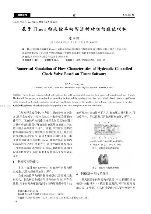
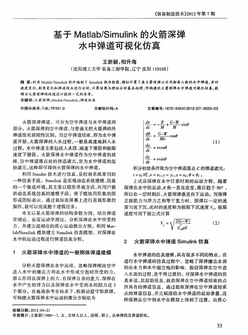
doi:10.3969/j.issn.1005-2798.2017.01.005基于Fluent 的液控单向阀流动特性的数值模拟康国俊(西山煤电集团公司屯兰矿,山西太原 030206)摘 要:利用流场仿真软件Fluent 对液控单向阀内部流场进行数值模拟,通过控制流量与阀芯开度对其内部流动性能进行分析,对液控单向阀的设计有借鉴意义,同时有助于提高液压系统的动态品质。
关键词:液控单向阀;阀芯开度;流量;数值模拟中图分类号:TD 文献标识码:A 文章编号:1005-2798(2017)01-0016-03Numerical Simulation of Flow Characteristics of Hydraulic ControlledCheck Valve Based on Fluent SoftwareKANG Guo-jun(Tunlan Coal Mine ,Xishan Coal Electricity Group Company ,Taiyuan 030206,China )Abstract :The hydraulic controlled check valve interior flow field was simulated using flow field numerical simulation software,Fluent.The internal flow property was analyzed by controlling the flow and the opening of the valve core ,which offered reference significanceto the design of the hydraulic controlled check valve and helped to improve the quality of the hydraulic system dynamic of the state.Keywords :hydraulic controlled check valve;opening of the valve core;flow;numerical simulation 在煤炭开采过程中,作为最主要的安全支护设备,液压支架对矿井安全高效生产起着至关重要的作用[1]。
基于Fluent数字仿真的水下清淤系统吸口优化设计

同理,我们可以运用 Fluent 软件处理
器对流场内质点速度情况进行分析,结合压力 图 6 窄口式吸口中轴面压力分布图 和速度进行综合分析,对四种方案的各自特点 总结如下表所述: 表 1 方案特点对照表
方 案 一 二 速度 变化 小 有急 变 有急 变 对称 分布 平面 surf 压力 出口处变化 明显 左侧有压力 死角 压力没有突 变 没有压力突 变、死角 系统功效评价 系统工作效率一般 死角的出现,导致淤泥堆 积,系统工作效率较低 系统工作效率较好 系统工作稳定,工作相对 效率较高 3
1 前言
因发电厂冷却水池中,一直存在着循环水 悬浮物含量高、淤泥沉积量大的问题,每间隔 4~5 个月就需对水塔水池清淤。 循环水系统内 大量悬浮物和淤泥的存在会给系统造成危害, 包括腐蚀铜管、降低换热效果、堵塞水塔喷嘴 甚至导致发电机组停机等恶性事故。 本文利用 Fluent 软件构造吸口三维模型, 划分网格,利用计算流体力学理论在给定压 强、泵吸流量、泥浆浓度、输送距离以及其它 工作环境的情况下,对吸口流场进行数值模 拟,模拟出吸口流场内的压力分布、相关截面 速度矢量图。根据模拟数据对吸口结构形式进 行选择,选择泵吸效率高的结构形式,并对其 结构进行优化设计,提高排泥浓度,改善吸口 的过流条件,防止过流不畅、淤塞的现象。
k
1.0
,
1.3 ,
1
1.44
, 2
。
2. 多相流模型:物质的三种状态称为三 相:固相、液相和气相。多相流就是指在流体 中不仅仅是单一形态的物质,而是有两种或两 种也上相态的物质同时存在并构成一种流动 状态。在 Fluent 中,共有三种多相流模型, 分别是 VOF 模型、混合物模型和 Eulerian 模 型。本文采用混合物模型来模拟吸口流场内各 相流动状态。
基于Matlab/Simulink的火箭深弹水中弹道可视化仿真
爹 c o s
d£
㈩
=z0O , s c : i0 sn
t
积分初始条件取为空中弹道落点 C的弹道诸元 : £ c , cY y , C0 。 =t 时 = , c =X , = 上式是深弹在水 中任意时刻 的运动方程 ,随着 深弹在水 中的运动 , 角一直在改变 , 0 最后趋 于 9  ̄ 0, 所 以在一定时刻后 , 火箭深弹垂直 向下运动。当深弹 正面阻力与浮力 之和等于重力时 ,深弹 以一定 的速 度匀速下沉 , 此时的速度称为极限下沉速度 。 极限 速度可用下面公式计算
、
3 6 3 6 3 7 3 7 3 8 3 8 3 9 40 , 5 4O 1 4 5 40 45 40
1 2 13 3 514 3 51 5 3 5 3 0 16 3 0 35 3 013 3 01 4 3 015 I 6 3 517
距离 ( m)
距 离( ) m
关 键 词 : 箭 深 弹 ; db S lk 弹 道 仿 真 火 Ma a/i i ; mun 中图 分 类 号 :J ; P 9 . T 6 T 3 19 文 献 标识 码 : A 文 章 编 号 :6 2 5 5 2 1 0 — 0 3 0 1 7 — 4 X( 0 2)7 0 3 — 3
不同的射角人水后 , 在水中垂直段的射角均变为 9 。 0;
航 天大学 出版社 。0 9 20 .
Ba e nt e Ma lb/ muik Ro k t p h Ch r e Un e wa e s d o h t a Si l c e n De t a g d r t r
l ・ 6 以某 火箭 深弹 为例 ,初始射 角分别 为 4 。和 5 15 ・ 1o 行 弹道仿 真 和分 析 。 2进 曼1 . 3 31 速度 变 化规 律 . 火 箭 深 弹 以一 定 的初 速 和射 角 到 达水 面 ,进入 水 中, 深弹首先作减速运动 , 然后进人极限下潜段。 以某火箭深弹为例 , 以两种不 同的初始射角 , 经过仿 真 系统 得 到 的速 度变 化 图如 图 2所 示 。
基于FLUENT软件的溢洪道三维泄流数值模拟
广西水利水电GUANGXI WATER RESOURCES &HYDROPOWER ENGINEERING 2018(4)[收稿日期]2018-03-20[作者简介]任庆钰(1987-),男,贵州毕节人,贵州省水利水电勘测设计研究院工程师,硕士,主要从事水利水电工程设计工作。
·试验研究·Fluent 软件具有20多年的发展历史,在航空航天、能源、汽车、化工、石油等领域得到了广泛的应用,是目前全球最高效、最精确和功能最强大的计算流体力学商用软件。
近年来,Fluent 软件在水利水电工程中的运用逐渐得到普及[1]。
本文基于Fluent 软件对某水库溢洪道进行三维水流数值模拟,并与物理模式试验结果进行对比,提出溢洪道三维水流数值模拟方法,该方法对于计算溢洪道沿程水面线、溢洪道泄流能力、动水压力及挑流长度效果较好。
1工程概况嘎醉河水库位于贵州省黔东南州凯里市舟溪镇东约1km 的鸭塘河上,距凯里市直线距离约11km ,距贵州省会贵阳公路里程约204km 。
工程建设的主要任务为城市供水,总库容1961万m 3,属Ⅲ等工程,水库为中型水库,年城镇供水量1720万m 3。
坝址正常蓄水位740.0m ,相应库容1961万m 3,面板堆石坝方案校核洪水位为742.74m (P =0.1%),总库容为1961万m 3。
取水隧洞设计引用流量0.68m 3/s 。
根据《水利水电工程等级划分及洪水标准》(SL252-2000)规定,该工程规模属中型,工程等别为III 等,永久性主要建筑物大坝为2级建筑物(坝高超过70m ),溢洪道、取水兼放空隧洞及泵站为3级建筑物。
2数学模型2.1控制方程[2](1)连续性方程:∂U i∂X i=0(1)(2)动量方程:U i ∂t +U j ∂U i ∂X j =-1ρ∂P ∂X i +∂∂X j ()ν∂U i ∂X j-----u i u j +1ρF i (2)(3)k 方程:∂k ∂t +U j ∂k ∂X j =∂∂X j éëêùûú()ν+νt σk ⋅∂k ∂X j +G -ε(3)(4)ε方程:∂ε∂t +U j ∂ε∂X j =∂∂X j éëêùûú()ν+νt σε⋅∂ε∂X j +C 1εεk G -C 2εε2k(4)2.2计算方法及边界条件采用标准k —ε两方程紊流模型计算,在计算域中采用有限体积法进行控制方程的离散。
基于Fluent的泵站侧向前池整流数值模拟及优化

— —
1
——
第 1 第 4期 7卷 21 0 1年 4月
水 利 科 技 与 经 济
W a e ns r a c c e c n c n lg n o my tr Co e v n y S in e a d Te h oo y a d Ec no
模拟引渠上下游部分沙井河河道 , 游至沙井水 闸。 下 本 文 采 用 Fu n 的 前 处 理 软 件 G mb 建 立 泵 站 整 体 let a i t
力参数基本合理 , 算结果 是可信 的 , 以用 数值模 拟方 计 可
法优化工 程 布置 方 案 、 究 泵 站 工 程运 行 的水 流 特性 。 研 在 配 水 渠 进 口左 侧 附 近 产 生 一 定 的 漩 涡 , 是 由 于 沙 井 这
三维模 型结 构和进行 网格划分 。网格形式 为 四面体
0 引 言
泵 站 前 池按 照 进 水 方 式 不 同 分 为 正 向进 水 前 池 和 侧 向进 水前 池 。正 向进水 前 池 的水 流 与进 水 池 水 流 的 方 向一
非结构化 网格 , 结构剧烈 变化部 分采用加 密措施 , 网格单
交进 水 方式 的研 究提 供 了可供 借 鉴 的研 究方 法。
[ 关键词】 泵站 ; u n; 力优 化 ; 池整 流 l F e t水 前
[ 中图分类号 ] 3/7 365 [ 文献标识码 ] B [ 文章 编号 ] 10 7 7 (0 1 o 0 0 0 0 6— 15 2 1 )4— 0 1— 2
水深对机枪密封式膛口流场影响的数值分析
水深对机枪密封式膛口流场影响的数值分析张欣尉;余永刚【摘要】为了探究水深对水下机枪密封式膛口流场的影响,文章运用流体计算软件FLUENT,结合用户自定义函数(UDF)和动网格技术,对12.7 mm滑膛式机枪在1 m、50 m和100 m水深条件下的密封式膛口流场进行了数值分析.计算结果表明:随着水深增大,弹丸初速降低明显而膛压略有升高;弹丸膛外行程在不同水深条件下均满足指数函数规律;弹丸水下运动过程中,速度衰减随着速度降低而加快;水深越大,膛口流场激波膨胀区域越小,马赫盘位置离膛口越近,膨胀区头部温度越高而速度越低;200μs时刻,随着水深增大,燃气射流在越过马赫盘后温度出现峰值次数减少.由此可见,水深对水下机枪密封式发射内弹道结果和膛口流场的影响具有一定规律.【期刊名称】《船舶力学》【年(卷),期】2019(023)005【总页数】8页(P558-565)【关键词】兵器科学与技术;水深;密封式膛口流场;燃气射流;数值分析【作者】张欣尉;余永刚【作者单位】南京理工大学能源与动力工程学院, 南京 210094;南京理工大学能源与动力工程学院, 南京 210094【正文语种】中文【中图分类】O354.5;TJ60 引言枪炮水下发射时,水的密度约为空气密度的800 倍,为保证发射安全性和威力,Stace 等[1]提出了水下密封式发射,即在膛口加装密封装置,当弹前空气压力达到某一数值时密封装置打开,随后弹丸运动出膛。
密封式发射时,膛口周围水介质将对弹丸运动和燃气射流的扩展产生较大影响,针对水深变化对密封式发射膛口流场影响的研究对于水下枪炮的研究具有一定理论意义和工程价值。
膛口流场对弹丸运动以及周围环境均具有重要的影响作用,对于枪炮在空气中发射所形成的膛口流场,国内外专家学者开展了大量研究工作。
Klingenberg 等[2]对7.62 mm 步枪膛口焰及温度进行了测量。
Jiang 等[3]针对马赫数为3.0 的高速射弹的膛口流场进行了数值模拟,捕捉并详细分析了其波系特征。
基于FLUENT的阻力计算

基于FLUENT的阻力计算FLUENT是一种流体力学数值模拟软件,可以用于求解复杂的流场问题。
在基于FLUENT进行阻力计算时,首先需要建立一个合适的流体模型。
该模型应该包括几何形状、边界条件以及流体的物理性质。
然后,通过设置计算参数和求解器参数,可以获得流体的速度分布、压力分布以及阻力等相关的物理量。
接下来,根据流体力学公式,可以计算物体在流体中所受到的阻力。
在计算物体阻力时,一般使用下面所列的一些常见的流体力学公式:1.基本阻力公式:阻力力=0.5*ρ*A*Cd*V^2其中,ρ是流体的密度,A是物体的参考面积,Cd是物体的阻力系数,V是物体的速度。
这个公式适用于表面光滑的物体和小速度范围内的情况。
2.卖力公式:阻力力=6*π*μ*R*V其中,μ是流体的动力粘度,R是物体的特征尺寸,V是物体的速度。
这个公式适用于小尺寸球体的情况。
3.麦克斯韦公式:阻力力=3*π*μ*D*V其中,D是物体的直径。
这个公式适用于小尺寸圆柱体的情况。
4. Darcy-Weisbach公式:阻力力=1/2*f*ρ*A*V^2其中,f是摩擦系数。
这个公式适用于管道流动的情况。
以上公式仅仅是一些常见的阻力公式,在实际应用中可能需要根据具体情况选择不同的公式。
基于FLUENT的阻力计算可以在建立流体模型后,通过设置边界条件来模拟物体在流体中的运动过程。
通过求解器可以得到流体的速度分布、压力分布等相关物理量。
根据上面介绍的公式,可以计算出物体在流体中所受到的阻力。
根据计算结果,可以评价物体在流体中的运动特性,进行优化设计或者进行流体力学研究。
综上所述,基于FLUENT的阻力计算是一种常用的数值模拟方法。
通过建立合适的流体模型、设置合理的边界条件和参数,可以模拟物体在流体中的运动过程。
根据流体力学公式,可以计算出物体在流体中所受到的阻力。
这种方法在工程实践中有着广泛的应用,并对于设计和优化物体的运动、流体管道的设计以及水动力学研究都具有重要意义。
基于ABAQUS的水下爆炸计算仿真实例

Modeling Submerged Structures Loaded byUnderwater Explosions with ABAQUS/ExplicitDavid B. WoyakABAQUS Solutions Northeast, LLCAbstract: Finite element analysis can be used to predict the transient response of submergedstructures that are externally loaded by an acoustic pressure shock wave resulting from anUnderwater Explosion (UNDEX). This class of problem is characterized by a strong couplingbetween the structural motions and acoustic pressures at the fluid-structure wetted interface. The structural behavior is a combination of long time (low frequency) response dominated by anadded mass effect, short time (high frequency) response dominated by radiation damping, and intermediate time-frequency response where both added mass and radiation damping behaviorare present. For the finite element method to be useful, the analyst must develop modelingtechniques and procedures that yield accurate and computationally tractable solutions. Modeling procedures and guidelines were developed for use with an explicit dynamics code that offersadvanced features such as: pressure formulated acoustic elements, surface based fluid-structure coupling, surface based absorbing (radiation) boundaries, and automated incident wave loadingfor the fluid-structure wetted interface. The modeling guidelines address issues such as: locationof the fluid acoustic domain outer boundary, meshing of the acoustic domain, representation ofthe shock wave, and solution efficiency. These modeling procedures and guidelines aredemonstrated with an ABAQUS/Explicit analysis of an UNDEX experiment in which a submergedtest cylinder was exposed to a 60-pound HBX-1 explosive charge (Kwon & Fox, 1993).General BackgroundABAQUS/Explicit is an efficient tool for simulating the transient response of structural-acoustic systems, of which the response of submerged structures loaded by acoustic shock waves resultingfrom an Underwater Explosion (UNDEX) is an important problem class. This paper provides abrief discussion on the general nature of the structural-acoustic interaction and describes modeling studies that address general Finite Element Analysis (FEA) requirements for the accuratesimulation of UNDEX problems. The studies described in this report have general application to awide range of structural-acoustic problems, not just the analysis of submerged structures. Anexample analysis of a submerged cylinder is used to illustrate an UNDEX problem.UNDEX analyses can be generally characterized as transient simulations of acoustic scattering behavior. However, the objective of an UNDEX analysis is to evaluate the response of thesubmerged structure and not necessarily the acoustic response. The finite element model for the external acoustic domain must be adequate to represent the influence of the water on the structural response. The discussion herein will be restricted to those cases where the external fluid behavesas a linear acoustic fluid with no cavitation. Therefore, the model of the external acoustic domainneed only be tailored to provide an accurate loading on the structure and does not need toaccurately represent the acoustic waves that will travel away from the structure. It should be noted2002 ABAQUS Users’ Conference1that procedures for UNDEX analyses which include fluid cavitation will be available inABAQUS/Explicit with the release of Version 6.3 (Prasad & Cipolla, 2001).The total acoustic pressure in the external fluid that results from an underwater explosion consistsof the known incident shock wave (incoming) pressure and the unknown scattered wave(outgoing) pressure. The scattered wave pressure consists of two parts, a reflected part that is associated with the shock wave interacting with an ideal rigid, immovable structure and avibratory part that results from the motions of the structure at the interface with the fluid. When cavitation is not present, it is desirable to let the external acoustic domain represent only thescattered portion of the total acoustic pressure. The shock wave incident pressure load is applieddirectly to the structural mesh at the fluid-structure wetted interface. Acoustic loads associatedwith the reflected part of the scattered pressure are applied to the fluid mesh at the wettedinterface. The full scattered pressure (reflected and vibratory) is obtained as the solution for theacoustic element pressure degrees of freedom, and the complete scattered pressure loading on the structure is generated through the fluid-structure coupling equations. The acoustic loads are a characteristic of the incident shock wave, and are obtained from the fluid particle accelerations ina direction normal to the surface that defines the fluid-structure wetted interface.In the discussion that follows the capability of ABAQUS/Explicit to efficiently perform UNDEX analyses is demonstrated. The ABAQUS features utilized in solving this class of problem are:1. Computationally efficient pressure based acoustic elements.2. Surface based automated acoustic-structure coupling.3. Acoustic-structure coupling for mis-matched meshes.4. Surface based impedance models for representing non-reflecting fluid boundaries.5. Automated shock wave loading at the fluid-structure interface.Acoustic Domain Outer BoundaryUNDEX problems are characterized by a strong coupling between the structural motions and acoustic pressures at the wetted interface. The system response in a strongly coupled structural-acoustic system can be described as being a combination of the following types of response:1. Late Time - Low Frequency: Characterized by structural wavelengths that aresignificantly shorter than the associated acoustic wavelengths. The effect of the externalfluid on the structure is that of adding an effective mass to the structure on the wettedinterface. The scattered energy within the acoustic domain remains near the structurewith very little energy radiating away from the structure.2. Early Time - High Frequency: Characterized by structural wavelengths that aresignificantly longer than the associated acoustic wavelengths. The effect of the externalfluid on the structure is to act as a simple radiation damper at the wetted interface. Mostof the scattered energy within the acoustic domain radiates away from the structure.3. Intermediate Time - Frequency: Characterized by structural wavelengths that are ofsimilar length compared to the associated acoustic wavelengths. The effect of the2002 ABAQUS Users’ Conference 2external fluid on the structure is that of adding both effective mass and damping to thestructure. Comparable levels of scattered energy remain near the structure and areradiated away from the structure.Due to the high density and bulk modulus of water the finite element model for an UNDEXanalysis must be capable of accurately simulating all three ranges of structural-acoustic response.It should be noted that for some other types of structural-acoustic analyses, where the fluid is verylight compared to the structure, not all response types may be of equal importance. For example,the added mass effect of air acting upon heavy structures is often of no consequence.The acoustic model for the outer boundary of the external fluid domain must provide adequatenon-reflecting behavior over all three time-frequency ranges. Non-reflecting outer boundarymodels are implemented in ABAQUS/Explicit (Version 6.2) via a surface based boundary impedance. ABAQUS has several imbedded surface impedance models, of which the circular and sphere types were used for analyses described herein. These impedance models are based upon the classical solutions for a 3-dimensional point source (sphere) and a 2-dimensional point source or3-dimensioanl linear source (circular). The default impedance model corresponds to a simpleplane wave radiation condition, which is well suit to simple acoustic tube test simulations.For the late time - low frequency response range, the extent of fluid contributing to the added massis largest for the longest structural response wavelength. Also, for the early time - high frequency response range, the longest structural response wavelength has the potential to generate efficient radiating acoustic waves with the longest wavelengths. Therefore, the location of the fluid meshouter boundary can be based upon the structure’s longest characteristic response wavelength. Ageneral guideline for locating the acoustic mesh outer boundary was developed by performing aseries of analyses representing the harmonic translational motion of a rigid infinite cylinder in aninfinite fluid domain. This type of motion is closely related to the transverse motion of a cylindersection for beam bending response modes. A 2-dimensional rigid cylinder cross section (10”radius) was placed within a circular fluid domain, for which the outer boundary was located at 2,3, and 4 cylinder radii. The fluid was water with a bulk modulus of 345,600 psi and a sound speedof 60,000 inches per second. ABAQUS/Explicit was used to drive the cylinder with a harmonicmotion until steady state conditions were achieved. Baseline analyses with very refined acousticmeshes were used to represent the exact solutions. The baseline analyses utilized linear acoustictriangle elements with approximately 42 element divisions per acoustic wavelength. The outer boundary for the baseline analyses was located two full acoustic wavelengths away from thestructure, and utilized the circular type impedance boundary. The boundary evaluation modelshad a minimum of 20 element divisions per acoustic wavelength for the highest driving frequency,and the maximum acoustic element size was set at 1.5 inches for the lowest driving frequencies.Figure 1 shows the baseline results for the complex radiation impedance of the driven cylinder(force/velocity). The impedance values are plotted against the ratio of the structural wavelength,which is the cylinder circumference, to the driving frequency acoustic wavelength. The radiation reactance (imaginary) represents an added-mass effect and the radiation resistance (real)represents the acoustic damping. Figure 1 clearly shows all three time-frequency response ranges,with the radiation impedance transitioning from added mass at low frequencies to radiationdamping at high frequencies. Figure 2 shows a plot of the error ratio for the radiation impedance predictions with the evaluation models. The radial thickness of the fluid mesh for the outerboundary at 2, 3 and 4 cylinder radii, corresponds to approximately 1/6, 1/3, and 1/2 of thestructural wavelength. Setting the boundary at 2 cylinder radii (1/6 structural wavelength) works2002 ABAQUS Users’ Conference3well at high frequencies but can introduce significant error in the added mass at low frequencies.The error oscillations within the 5% error range at the higher driving frequencies appear to be dueto the outer boundary being placed near integer multiples of half the acoustic wavelength. Placingthe outer boundary so that the fluid domain thickness is between 1/3 and 1/2 the largest structural wavelength provides for reasonable accuracy when using a sound source based outer boundarysurface impedance model. The performance when using a classical plane wave boundary conditionis significantly diminished, and would require at least doubling the extent of the fluid domain.Fluid Mesh Requirements for Representing the Shock WaveThe classical representation of a spherical shock wave associated with UNDEX loading is characterized by an instantaneous pressure rise to a peak value followed by an exponential decay.An UNDEX analysis in which the external fluid is modeled with finite elements cannot accurately represent a shock wave having an instantaneous pressure rise because the infinite pressure gradientat the shock front implies infinite fluid particle acceleration, so that the acoustic loads associatedwith the reflected part of the scattered pressure become indeterminate. Therefore, the shock frontmust be modeled such that the pressure rise occurs over a period of time, designated the “risetime”. A reasonable value for the rise time can usually be obtained from experimental oranecdotal data. The pressure vs. time history of the shock wave at a known distance form thesource can be used to evaluate element size requirements for the acoustic mesh. This isaccomplished by means of a simple acoustic tube evaluation model.A simple acoustic tube model was constructed with the linear tetrahedron acoustic elements thatwill be used in the subsequent UNDEX example analyses. Acoustic loads representative of aplanar shock wave are applied at one end of the model with the ABAQUS incident wave loading capability. The end at which the loads are applied represents a rigid immovable wall. Theresulting reflected wave travels down the acoustic tube. A simple plane wave absorbing boundarycan be applied to the opposite end of the tube, or the tube can be made of sufficient length so thatthe test analysis finishes before the reflected wave reaches the opposite end.Figure 3 shows the results for a tube analysis in which the nominal element size is equal to 1.5times the wave propagation distance corresponding to the rise time of the shock front. The onlyoutput quantity of concern in these acoustic tube analyses is the pressure at the rigid wall(scattered pressure). An ideal solution for this problem would have the reflected wave being anexact copy of the shock wave. This is clearly not the case for the Figure 3 model. Figure 4 isanother analysis with the element size set at 1/4 the rise time propagation distance. The scattered pressure matches the shock pulse very well. However, there is still a fair degree of oscillation inthe early time solution. It should be noted that the range in the pressure oscillations can become noticeably less when using brick type acoustic elements.Figure 5 shows some additional solutions with the element size set at 1.5 times the rise timedistance, for which the time increment was varied via direct user control. As the time increment is reduced the mean response approaches that of the incident shock wave. This illustrates howsimple acoustic tube models can also be used to evaluate the time increment requirements foraccurately representing the reflected wave loading. Figure 5 also suggests that a relatively coarsefluid mesh may provide sufficient solution accuracy for the structural response as long as thestructure being analyzed responds at low frequencies relative to the reflected wave oscillations.For these cases, the pressure impulse (time integral of pressure) associated with the reflected and2002 ABAQUS Users’ Conference 4incident shock waves should have relatively good correlation. Figure 6 shows the pressure impulse curves generated from the Figure 5 analyses, and suggests that using a time increment that is lessthan or equal to 1/20 of the rise time may provide good results with the coarse acoustic mesh for alow frequency structural system.Example Problem DescriptionThe UNDEX example problem is based upon an experiment in which a submerged test cylinderwas exposed to a shock wave produced by a 60-pound HBX-1 explosive charge (Kwon & Fox, 1993). The test cylinder is made of T6061-T6 aluminum, has an overall length of 1.067 meters, an outside diameter of 0.305 meters, a wall thickness of 6.35 millimeters and welded endcaps that are24.5 millimeters thick. The cylinder was suspended horizontally in a 40-meter deep fresh watertest quarry (sound speed =1463 meters/second). The 60-pound HBX-1 explosive charge and the cylinder were both placed at a depth of 3.66 meters, with the charge centered off the side of thecylinder and located 7.62 meters from the cylinder surface. The suspension depths, charge offsetand duration of the test were selected such that cavitation of the fluid would not be significant andno bubble pulse would occur. During the UNDEX test, two pressure transducers were positioned7.62 meters from the charge, away from the cylinder, but at the same depth as the cylinder. These transducers provided an experimental determination for the pressure vs. time history of theincident spherical shock wave as it traveled by the point on the cylinder closest to the charge.Figure 7 is a time history of the recorded shock wave pressure used as input to theABAQUS/Explicit analyses. Strain gages were placed at several locations on the outer surface ofthe test cylinder, as shown in Figure 8. The strain gage experimental data was filtered at 2000 Hz,with the experimental data presented herein obtained by digitizing the published Kwon & Foxstrain data.ABAQUS/Explicit Model & ResultsThe test cylinder was meshed with 2400 S4R finite strain shell elements and contained 2402 nodes (14412 dof) on 40 circumferential and 53 axial element divisions. The element connectivity issuch that each shell normal is directed into the external fluid. The shell element nodes arepositioned on the outside surface of the test cylinder. The cylinder body elements directlyadjacent to the endcaps have reduced mass & stiffness and are only used to provide a surface that corresponds to the thickness of the endcaps. BEAM type MPCs are used to rigidly tie theendcaps to the main cylinder body.The external fluid is meshed with 4-noded AC3D4 acoustic tetrahedral elements. The outerboundary of the external fluid is represented by cylindrical and spherical surfaces with theappropriate surface impedance absorbing conditions. The characteristic radius of the fluid outer boundary is set at 3 shell radii, thus the thickness of fluid modeled about the cylinder represents approximately 1/3 of the cylinder’s outer circumference (rigid body translational wavelength).Based upon the mesh boundary study this location should be sufficient to provide reasonablyaccurate results. Figure 9 shows the cylinder and first acoustic mesh that was used in the analysis,with the top half of fluid removed for clarity. The shock wave rise time is 0.0182 milliseconds, corresponding to a wave propagation distance of 0.0266 meters. The nominal element size at thewetted interface is also set at 0.0266 meters and increases in size to a nominal 0.080 meters at the2002 ABAQUS Users’ Conference5outer fluid boundary. An acoustic element size of 0.080 meters corresponds to approximately 12 element divisions per acoustic wavelength for a 1500 Hz response. Figure 10 provides the resultsof the acoustic tube validation for this degree of mesh refinement. Acoustic Mesh #1 contains39186 elements and 7947 pressure degrees of freedom. Figure 11 shows the second acousticmesh that was used in the analysis, with the top half of fluid removed for clarity. The nominalelement size at the wetted interface is set at 0.010 meters and increases in size to a nominal 0.030meters at the outer fluid boundary. Figure 12 provides the results of the acoustic tube validation corresponding to acoustic Mesh #2, which contains 463114 elements and 87745 pressure degreesof freedom.Figure 13 shows the ABAQUS predicted axial strain response at strain gage location B1 whenusing the coarse (#1) and refined (#2) acoustic meshes. The response curves are very close both in magnitude and phasing. The close correlation between the two analyses was also apparent at theother strain gage locations. This indicates that for the applied UNDEX loading the structuralresponse times are long when compared to the reflected wave oscillations obtained in the acoustictube validation analyses. This result was predictable when considering an eigenvalue analysis forthe cylinder with no external fluid. The modes that have the greatest potential for producingdamage have frequencies well below 1500 Hz, and will be further reduced when the cylinder is submerged due to the added mass effect. The cylinder modes have response periods that are significantly longer than the shock wave rise time or reflected wave pressure oscillations. Thus,for this particular example, using an acoustic mesh and solution time increment that reasonablycaptures the shock wave reflected pulse and can represent the scattered acoustic waves at thestructural response frequencies is adequate for obtaining a good solution.The response shown in Figure 13 is dominated by the fundamental beam bending mode of thecylinder, for which the dominant motion is transverse to the cylinder axis. At any point along the cylinder axis the motion is dominated by a translation of the cross section through the fluid,similar to the motion used in the infinite cylinder modeling study. The only damping mechanismsin the analyses were due to acoustic radiation and the /Explicit default values for element bulk viscosity. The acoustic model does not include any losses due to hydrodynamic drag (fluidviscosity) associated with the motions of the cylinder. The effect of hydrodynamic drag on thelate time response of the cylinder is clearly shown in Figure 14, where the predicted axial strain response is compared to the experimental data. The experimental data was digitized from apublished curve (Kwon & Fox, 1993), and was shifted by 0.2 milliseconds in order to align the experimental and analysis time axes. The solution designated as ALPHA = 0, represents theoriginal analysis, whereas the analysis designated as ALPHA=750 utilized mass proportionaldamping (10% critical at 600 Hz) applied to the cylinder as an approximation for the effects of hydrodynamic drag. The application of ALPHA damping does not have an adverse effect on thesolution critical time increment. ALPHA damping does not significantly affect the early timeresponse (high frequency), but does significantly reduce the late time response (low frequency).This is consistent with what is observed with the experimental data. In any event, ignoring hydrodynamic drag in an UNDEX analysis will produce conservative (high) levels for thestructural response, which is often a desirable trait when doing a design evaluation analysis.Figure 15 shows the levels of Accumulated Plastic Strain (PEEQ) on the outer surface of the shellat the end of the analysis with fluid Mesh #1 and ALPHA= 750. No change occurs in the peakplastic strain level of the cylinder wall after the first 0.34 milliseconds. Recalling that the entireshock pulse duration is 2.0 milliseconds, this truly is an early time response. No change occurs inthe peak accumulated plastic strain of the endcaps after 2.84 milliseconds, which indicates that the2002 ABAQUS Users’ Conference 6endcap response may be influenced to a greater extent by the late time response. Unfortunately,there were no strain gages attached to the endcaps and the cylinder wall gages located in theregions of high plastic strain failed during the test. Table 1 compares the peak accumulated plasticstrains obtained with the two acoustic meshes, with and without ALPHA damping. The results comparison between Mesh #1 and Mesh #2 is very good. The effect of ALPHA damping on thecylinder wall PEEQ is very small, but is significant for the endcap response. Table 1 also providesa comparison of the solution times for the analyses, and illustrates the solution efficiency of theacoustic elements as compares to structural elements.ConclusionsABAQUS/Explicit provides an efficient means to evaluate the transient response of structural-acoustic systems loaded by external acoustic sources. This was illustrated with the analysis of a submerged cylinder acted upon by a shock wave generated by an underwater explosion. Themodeling studies presented in this paper indicate that sufficient accuracy for a submergedstructure’s response can be obtained when positioning the external absorbing boundary of theacoustic domain a distance from the structure of between 1/3 to 1/2 the longest characteristicstructural wavelength. Modeling studies also indicated that the degree of refinement in theacoustic domain mesh can be tailored to the characteristics of the shock pulse and the nature of structural response, i.e., short vs. long response times as compared to the shock pulse transient.Table 1. Model statistics and results comparisons.Item Cylinder Only Acoustic Mesh #1 Acoustic Mesh #2 No. Acoustic Elements N/A 39186 463114No. Acoustic DOF N/A 7947 87745No. Shell Elements 2400 2400 2400No. Shell DOF 14412 14412 14412Solution Time Increments 4730 4730 13873CPU Time (Seconds) 281 426 4590CPU per Increment 0.059 0.090 0.331PEEQ Cylinder Wall(Alpha = 750) N/A 0.00820 0.00810PEEQ Cylinder Wall(Alpha = 0) N/A 0.00838 0.00828PEEQ Endcap Center(Alpha = 750) N/A 0.00626 0.00611PEEQ Endcap Center(Alpha = 0) N/A 0.01007 0.009852002 ABAQUS Users’ Conference78 2002 ABAQUS Users’ ConferenceFigure 1. Baseline radiation impedance results for an infinite rigid cylinder.Figure 2. Error ratio for the radiation impedance evaluation models.2002 ABAQUS Users’ Conference 9Figure 3. Acoustic tube with elements 1-½ the rise time propagation distance.Figure 4. Acoustic tube with elements ¼ the rise time propagation distance.10 2002 ABAQUS Users’ ConferenceFigure 5. Additional results for 1-½ rise time element mesh.Figure 6. Pressure impulse curves from Figure 5 analyses.Figure 7. Incident shock wave pressure transient.Figure 8. Test Cylinder Strain Gage Locations.2002 ABAQUS Users’ Conference11Figure 9. Cylinder and acoustic Mesh #1.Figure 10. Acoustic tube validation results for Mesh #1. 12 2002 ABAQUS Users’ ConferenceFigure 11. Cylinder and acoustic Mesh #2.Figure 12. Acoustic tube validation results for Mesh #2. 2002 ABAQUS Users’ Conference 13Figure 13. Axial strain response at gage location B1.Figure 14. Comparison plots of response at strain gage B1.142002 ABAQUS Users’ ConferenceFigure 15. Accumulated plastic strain in the test cylinder.References1. Kwon, Y.W. and P.K. Fox, “Underwater Shock Response of a Cylinder Subjected to a SideOn Explosion,” Computers and Structures, Vol. 48, No. 4, 1993. 2. Prasad, B.R. Nimmagadda and J. Cipolla, “A Pressure Based Cavitation Model for Underwater Shock Problems,” Shock and Vibration Symposium, Paper U30, November, 2001.2002 ABAQUS Users’ Conference15。
- 1、下载文档前请自行甄别文档内容的完整性,平台不提供额外的编辑、内容补充、找答案等附加服务。
- 2、"仅部分预览"的文档,不可在线预览部分如存在完整性等问题,可反馈申请退款(可完整预览的文档不适用该条件!)。
- 3、如文档侵犯您的权益,请联系客服反馈,我们会尽快为您处理(人工客服工作时间:9:00-18:30)。
基于FLUENT的水下子弹数值模拟
一、问题介绍
Fluent是目前处于领先地位的CFD软件包之一,它为流体力学领域提供了强大丰富的计算平台。
针对各种复杂流动的物理现象,fluent可以采用不同的离散格式和插值方法,在特定区领域内使计算速度、稳定性和精度等方面达到最佳组合。
但是针对特殊的物理情景,其自身无法提供完全近似的物理模型,必须通过其自带的自定义函数UDF(user Defined function)对其进行二次开发。
例如,对于水下航行的子弹,现有的模块不能模拟子弹运动过程,只能给定一个逆向的速度入口边界条件来实现,即水动子弹不动。
为了更近似的模拟子弹运动过程,需要对FLUENT进行二次开发。
本文采取的方法是利用用户自定义函数UDF,对fluent进行二次改造,采用动网格技术,对子弹匀速运动进行模拟。
二、物理平台
本文用到的软件包括:前处理软件gambit,计算软件fluent12.0,UDF支持语言microsoft visual C++6.0,后处理软件tecplot.
Gambit用于建立几何模型,划分网格。
本算例采用二维轴对称模型,子弹以一矩形近似代替。
Fluent用于计算子弹运动流场特性,包括速度,压力,阻力等。
本算例涉及到子弹运动,需要采用动网格技术,即网格在计算过程不断变化更新,因此通过UDF对fluent进行二次开发。
其中UDF是fluent自带的宏命令,其运行环境是C语言,所以必须在计算机中提空支持C语言的运算环境microsoft visual C++6.0(也可以是其他更高版本)。
Tecplot为计算结果后处理软件,可以制作动画,云图等。
三、动网格简介
1.spring based smoothing 弹簧近似光滑模型
2.dynamic layering 动态分层模型
3.local remeshing 局部重构模型
三种动网格技术有自己的使用范围,其中弹簧近似光滑模型对于结构和非结构化网格都适用,对于模拟物体小范围运动或者变形有巨大优势,而对于大范围移动却无法实现,一般情况下此方法很少单独使用,通常是配合后面两种动网格技术使用。
网格局部重构模型只适合四面体网格和三角形网格,可以用于模拟大范围平移和旋转,同时在模拟复杂边界移动具有很大优势。
动态分层模型只是用于结构化网格,对于三角形和四面体网格则毫无用处。
由于本文采用此方法,这里讲具体介绍此模型:
动态分层模型(dynamic layering),对于规则计算域,划分规则四边形网格后,采用此模型有利于实现物体的单方向平动,其优点是不需要网格重构,不会改变运动体周围的网格形态,节约了网格更新的时间,同时能保证网格一致性,提高计算效率。
此方法的弱点在于无法模拟物体旋转运动,无论对于二维还是三维模型,只能解决物体平动问题。
此方法的思想是当网格边界缩短小于设定值时自动与上一个网格合并成,而当网格被拉伸小于设定的最大网格线长度时,又自动分裂成两个网格。
无论是哪种动网格模型,对内部的参数设置要求十分严格,若参数设置不当,可能出现
负网格,因此,在进行划分网格时候,严格记录各关键部位尺寸,计算前,最好进行网格预览。
四、本文算例介绍
1、几何模型
本文将模拟子弹在水下运动过程,分别设定子弹以20m/s,,25m/s,30m/s在水下匀速运动,观察子弹周期的压力场,速度场以及空化情况,在此基础上选取30m/s运动速度采用动网格技术进行模拟,意在指明子弹与水的相对运动关系的区别。
为了节约计算资源,子弹简化为一长30mm,宽10mm,计算区域长300,宽100mm。
全域采用四边形结构化网格,同时在子弹周围网格加密。
网格总数15050,最小网格0.375mm。
因为计算物体和计算区域高度对称,因此截取一半采用二维轴对称方式计算。
计算网格及边界条件如图1所示:
图1
2、计算方法
将网格导入fluent12.0中,本文所有算例采用标准k-epsi湍流模型,离散方法为piso算法,打开空化模型。
不同速度算例均为定常情况,动网格模型为非定常模型,其时间步长0.0001s。
3、计算结果
算例1:下图为20m/s,25m/s,30m/s速度下,子弹的空泡云图,速度云图和压力云图,从图2中可以看出随着速度增大,空泡尺寸相应增大,子弹周围压力减小。
当达到30m/s 时,子弹几何被整个气泡包裹。
空泡尺寸速度云图压力云图
图2
以上算例均以子弹不动,在左边界给一个速度入口边界条件,以水相对子弹运动来代替自带在水中运动,此种方式在数学理论上符合逻辑,但是是否符合物理实际,现在众说纷纭。
在相关领域也有相应的实验场地,均采用此种方式模拟真实的子弹或者其他水下航行体运动。
由于子弹运行距离较长,不可能在实验中实际检测子弹的运动,因此,此方法在理论和实验方面都具有很强的优势。
算例2:选取30m/s运动速度,采用动网格技术,模拟子弹在水中航行。
程序代码如图3
图3
具体操作步骤如下:
因计算机为双核处理器,所以在并行计算时候只能选取双核并行,若计算机性能足够强大,可选择多核并行,如图4标注。
图5 图6
本算例采用动态边界层动网格模型,在相应的模型前选中即可,内部的分裂因子保持默认,如图6。
此模型需要把整个流域以及子弹作为运动物体同时运动,并且入口和出口设置为不动边界。
此处动网格能否实现的关键在于运动体的参数设置。
其中的cell hight均为y方向的最小网格尺寸,若设置成x方向,则无法运动。
同时必须保证,s为最小网格尺寸, 为时间步长,v为物体运动速度。
为了与定常30m/s具有可比性,本算例所以计算方法,参数以及边界条件与30m/s定常运动完全一致,不同之处在于来流速度为0,子弹以30m/s速度向右运动。
计算之前最好先进行动网格预览。
图7是不同时刻子弹空泡发展情况:
图7
从云图可以看出,随时间增大,空泡尺寸不断变大,最后发展成为一个超空泡。
由于计算区域较短,后面时候子弹运动靠近边界,数据不稳定,可认为此时空泡已经完全发展。
由于计算时间较少,若延长计算时间,可看到空泡脱落现象。
为了说明动网格计算结果与定网格计算结果的差异,将30m/s定常结果与动网格模拟结果做对比,由于定常算例计算的是稳定后的空泡形态,因此必须以动网格计算空泡形态稳定后结果作为对比,如图8所示:
图8
图8看出定常计算和动网格计算在形态上有着明显的差别,动网格计算的空泡尺寸和尾部倒流情况明显不同于定常计算结果。
至于哪个结果更符合物理实际,需要与相应的实验数据做对比。
由于精力和条件限制,此处没有实际实验数据提供参考,此项工作将是后续工作重心。
五、结论和展望
通过以上算例计算,验证了动网格技术的可行性。
动网格技术,可以捕捉物体的完整运动过程,对于工程实际可以提供相应的技术参考。
动网格技术也存在很大的缺陷,例如计算时间巨大,对计算机性能要求高,因此,优化网格结构,简化计算方法,提高计算效率是动网格发展的必然趋势。