控制器流量控制的说明书
ALICAT 流量计 流量控制器 简易操作指南说明书

针脚号DB15 DB15K DB9/DB9M 8针mini-DIN 6针工业接头 1 接地 不接 4-20mA 输出 4-20mA 输出 电源正 2 模拟输出 模拟输出 第2路模拟出 第2路模拟出 TX(+)发送 3 接地 不接 RX(-)接收 RX(-)接收 RX(-)接收 4 不接 不接 模拟输入 模拟输入 模拟输入 5 电源正 接地 TX(+)发送 TX(+)发送 接地 6 不接 不接 0-5V 输出 0-5V 输出 模拟输出 7 不接 电源正 电源正 电源正 8 模拟输入 模拟输入 接地 接地 9 接地 第2路模拟出 接地 10 接地 不接 11 第2路模拟出 接地 12 不接 接地 13 RX(-)接收 RX(-)接收 14 接地 TX(+)发送 15 TX(+)发送 接地ALICAT 流量计/流量控制器简易操作指南1.外观概览2.针脚定义流量方向比例阀 背光灯开关功能键 屏幕电源插孔通讯线接口NPT 螺纹接口安装螺孔8-32 UNC3.功能按键3.2屏幕背光灯:按屏幕下方红色ALICAT 商标 可打开/关闭屏幕背光灯。
3.3切换输入信号源:进入菜单Menu ,在Control – ADV Control – SETPT Source 中可切换数字信号控制或模拟信号控制。
Serial/Front Panel 即数字信号/面板控制,Analog 即模拟信号。
3.4切换控制对象:在Control – ADV Control – Loop Setup – Loop VAR 中可切换控制对象为质量流量、体积流量或压力。
默认为质量流量。
3.5调节PID 增益:在Control – ADV Control – Loop Setup – Loop Gains 中可调节PID 增益值。
PID 值会影响控制器的稳定性和响应速度。
3.6输入设定值:在对应的信号模式下可分别使用数字信号、面板按键、模拟信号来输入设定值。
IFC-125 气体流量控制器说明书

How to communicate with the [IFC-125 Valve] by DeviceNet masterDeviceNet Master series:DeviceNet Master series includes the USB interface(I-7565-DNM), PCI interface(PISO-DNM100U) and PAC module(I-8124W). They can represent an economic solution of DeviceNet application and be a DeviceNet master device on the DeviceNet network. They support Group 2 only Server and UCMM functions to communication with slave devices. They are popularly applied in the industrial automation, building automation, vehicle, marine, and embedded control network.CELERITY UNIT IFC-125 :Celerity Mass Flow Controllers Precisely monitor and control the mass flow of gases in processes such as Plasma Etching, CVD, Diffusion, EPI, and Sputtering where superior accuracy is required. Mass Flow Meters are identical to mass flow controllers, except that they do not have a controlling valve. Therefore they do not control, but only accurately measure and report the gas flow that is passing through them.The pictures came from the manual and are belonged to the Celerity.Wire connection with the DeviceNet Master:The users need to provide extra DC 24V power in M12-5PIN of the V+(pin-2) and V-(pin-3) for the DeviceNet module.DNM UtilityThe software utility includes various useful functions which help users to diagnose and access the DeviceNet devices. The users do not care about the protocol and configurations. The users could download from the website below.ftp:///pub/cd/fieldbus_cd/devicenet/master/dnm_utility/Set the UNIT IFC-125 MAC-ID = 19The DNM Utility is communicating with the UNIT IFC-125 valveThe node #19(IFC-125 valve) supports Poll connection. The Poll connection is with 3-byte input data and 2-byte output data which indicates the valve information.。
JMC流量控制器使用说明书

--系统设置
系 数--
A:1.0002
[ENTER]:修改
B:1.0002
[ESC]: 返回
C:1.0002
3、K 值系数: 该系数表示的是流量计探头的 K 值系数,其具体参数需参照后面提供的流量计探头的 K 值表
C#=3#
1# 反馈 接点 输入
2# 反馈 接点 输入
3# 反馈 接点 输入
上排端 子为电 磁阀的 继电器 输出
NO COM NC
NO COM NC NO COM NC
1#通道 2#通道 3#通道
下排端 子为再 生信号 的继电 器输出
NO COM NC NO COM NC NO COM NC
1#罐体 出水阀门 之电磁阀 220V/AC 1#JMA内部接线示意图
操作人员不得随意清除总累计流 量,如果特殊情况必 须要对总累计流量进行 清除时需向供应商寻 求技术支持。累计清零需要对各个回路进行清零。
6、强制: 其功能就是在剩余流量 还没有到达零 时,进行强制再 生信号输出,强 制再生信号结 束后,剩
余流量(批量)将恢复到设定值,强制分就地和远端两种。 就地强制可以在控制器上操作: 当在主菜单选择强制再生后,按动 ENTER 键则出现以下画面:
三、主要技术指标 ·流量传感器脉冲量输入:
A:SIGENT 探头,正弦波 频率范围 0-150Hz,探头(直流)电压幅度 4-12V B:JK-TT 探头,脉冲方波 频率范围 0-150Hz,探头(直流)电压幅度 6-12V ·采样周期:0.2 秒 ·批量值设定范围:1-9999t(吨) ·批量输出形式:继电器无源接点输出 ·外部信号及馈电输入:无源接点反馈信号(2 秒钟以上) ·传感器探头自带电缆:5 米 ·显示方式:背光液晶显示单元,使用寿命≥10 年 ·再生信号输出:(2-9999 秒可调),3 路继电器无源接点,触点容量,AC220V/2A ·控制电磁阀信号输出:3 路继电器无源接点 触点容量 AC220V/2A ·仪表电源:开关电源 100-265V/AC 功耗 5W ·使用环境:环境温度 4-60℃ 相对湿度 ≤85%RH ·与 JKA 多阀控制器专用配套 ·匹配反馈型多路阀:AUTUTROL 及 FLECK 等多路阀(需 450 控制器支持)
TSC系列质量流量控制器用户手册说明书
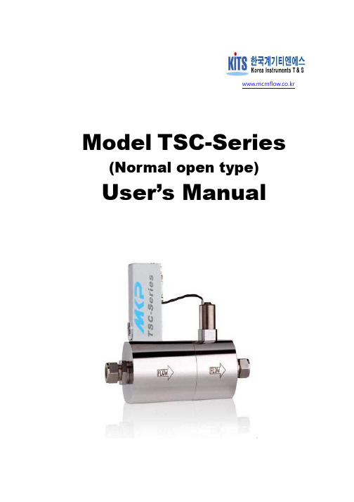
www.mcmflow.co.kr Model TSC-Series(Normal open type)User’s ManualTable of Contents1. Overview2. Specifications3. Dimensions4. Wiring diagrams5. Ordering Information6. Usage method7. Handling precaution8. Warranty1. Overview1.1 FeaturesTSC- Series are independently developed (possess various patents) MFC by Original Korean Technology. Depending the model, it can be applied up to 100 bar in pressure,it has characteristic to directly measure and control gas mass flow almost having no problem or no bearing to the pressure and the temperature changes with the sensor principle.TSC Series can practically use from the applied flow ranges of small flow (5sccm) to large flow (2500lpm), and for the special model, it is possible to manufacture MFC that can function in a very small pressure gauges. Nearly 10 years of R&D and production experiences, TSC Series is acknowledged for its product quality that supplies major domestic user companies such as Samsung Electronics, Hynix, and other public enterprises and exporting globally.MFC(mass flow controller) is composed of sensor, actuator, and control circuit. When the flow passes through the MFC, there will be differences in the temperature on top and bottom part of the sensor area that works to decide generating power ratio of the flow, then by comparing with the external setting signal and the power output, MFC automatically opens the valve to control. These consecutive movements make the equal signal.1.3 Major parts – Sensor<Sensor Outline>1. Utilizes tube structures that was made by the ultra-precision processing technology2. Carries two installed precision sensors which help to perform the sensitive sensing.3. Selected sensor structure that can make an absolute external balance.4. Applied structure technology that perfectly harmonizes the tube and bypass.5. Designed to make sure that its characteristics do not change in the long time usage.1.4 Major parts – BypassBypass parts has applied a manufacturing technology that applied the patent technology to give the perfect alignment with guarantee. Flow measurements are done by the sensor, yet most of the flow flows by the bypass and is structured to have an alignment relationship where it can measure the entire flow.2. SpecificationsFlow range 0 ~3000 LPMFlow rate control range 2~100%±1.0% of F.S.Accuracy±0.2% of F.S.Linearlity±0.2% of F.SRepeatablityResponse time less than 1~ 2 secondsWarm up time 15min (precious measurement 30 min)Circuit type AnalogPower supply +15VDC~ +24VDCInput/output signal 4~20mAConnector D-sub 9 pinControl valve type Solenoid valve (Normally Opened)Standard fittings SWLok Type0~50℃( recommended temp. range 15 - 30℃) Operating temperatureMax. operating pressure Max. 100 bar(g)Operating humidity less than 85%RHMaterial SUS316L※NOTEa) Apply the conversion factors when applying for gases other than the nitrogen, and air.For the detailed information, refer to the homepage. (www.mcmflow.co.kr )b) For the detailed specifications per model, refer to the homepage. (www.mcmflow.co.kr)3. Dimensions- Model : TSC-150-VO (unit: mm)※NOTEa) Special specification can be produced.b) For the detailed specifications per model, refer to the homepage. (www.mcmflow.co.kr)4. Wiring diagram* MFC Connector Out View : D-Sub 9 MalePin Number.Function1NC2Output Signal (4-20mA)3Setpoint (4-20mA)4Power Common5NC6NC7Power (+15VDC ~ +24VDC)8Power /Signal/PLC Common9FG※NOTE1. Power common pin must be directly connected by an independent line of the readout box or the common terminal of the electricity supply equipment.2. FG pin must be connected to the sash ground.3. For the detailed specifications, please refer to the homepage. (www.mcmflow.co.kr)4. When you use PLC application you have to join pin8.5. Ordering Information6. Usage method1) Keep attention to the flow and connect to MFC gas line.2) Utilize power supply than can supply more than DC 200mA and exact power to MFC.3) In general, it is okay to use the power supply directly. However, warm up for 15 minutes after supplying the power for the precision purpose.4) Correctly establish the pressure.5) Insert MFC control in.Setting Value(MFC Control in) = Needed flow* 5.000V mfc flow7. Handling precautions1) Within the valve there should never be liquids such as water, oil, vapors.- Each valve must supply clean gas without containing the dust. Dust will deteriorate theaccuracy and cause the block which makes the control impossible.2) Valve should not leak and should be installed after completing the purge procedures.3) When connecting the valve (fitting), one must use the spanner and a vice.4) For the MFC be safely remain with the pressure in the front/rear part, one should make the system or the equipment.5) In order to completely shut the flow, it is preferable to install a manual valve.6) Do not reach over 5V for the MFC control in.7) Be careful connecting the electric power.8) In the condition where the power is on, do not draw out the cable or reconnect. This can cause the mal function.9) Do not use other gas other than what is used.- Contact if it is necessary.10) Do not shock.11) Keep it fixed when using it.12) Do not disassemble.13) TSC- Series converts the flow amount at 20℃, 1013hPa(1atm) or0℃, 1013hPa(1atm) to calibrate 0 value.8. Product warranty1) Warranty periodFree repair or exchange when the product breaks within 1 year of the purchase.2) Warranty rangeWarranty is limited to the main frame, and the company will not be responsible for damage problems other than the body.3) Warranty for the repaired parts90 days after the repair, separate from the warranty period.4) ExemptionsCompany will not be responsible within the warranty period in cases stated below.1. Damages due to the natural disaster2. Damage caused by mistreatment3. Damages caused due to the operation in an inappropriate environment.4. Damages caused by the excess ranged setting.5. Damaged occurred by other productsKorea Instruments T&S disassembles and inspects A/S products to find out if it will be charged or free of charge for the repair.。
D07-7B 7BM 质量流量控制器使用手册说明书

D07 - 7B 型质量流量控制器D07-7BM 型质量流量计使 用 手 册目录1. 使用须知...................................1 6.2.1 开机预热 .. (15)2. 用途和特点..............................1 6.2.2 检查和调整零点 (15)3. 主要技术指标...........................3 6.2.3 通气工作 (15)4. 结构和工作原理........................4 6.2.4 关机 (15)4.1 结构.......................................47. 注意事项 (15)4.2 工作原理.................................57.1 禁用流量介质 (15)5. 安装和接线 ...........................77.2 使用腐蚀性气体问题 (15)5.1 外形及安装尺寸........................77.3 阀口密封问题 (16)5.2 气路接头形式...........................87.4 阀控操作注意 (16)5.3 连接电缆插头...........................97.5 安装位置问题 (16)5.4 与计算机或外部信号的连接.........117.6 注意工作压差 (16)5.5调零和外调零...........................127.7 标定和不同气体的换算 (17)6. 使用方法和操作步骤..................137.8 D07-7B,7BM标准订单填写格式 (18)6.1 质量流量控制器的操作...............138. 故障判断和处理 (21)6.1.1 开机操作..............................139. 保证、保修与服务 (23)6.1.2 清洗功能..............................149.1 产品保证和保修.. (23)6.1.3 显示仪与计算机连接的操作......149.2 保修对使用的要求.. (23)6.1.4 直接与计算机连接的操作.........149.3 服务.. (23)6.1.5 阀控功能..............................1510. 附录 (24)6.1.6 关机操作..............................1510.1气体质量流量转换系数 (24)6.2 质量流量计的操作 ...................1510.2转换系数使用说明 (26)MASS FLOW CONTROLLER & MASS FLOW METER第 1 页 共 26 页质量流量控制器和质量流量计使 用 手 册1. 使用须知尊敬的用户,感谢您购买本公司生产的D07系列质量流量控制器/质量流量计产品。
东星智能流量控制器说明书

东星智能流量控制器说明书一、概述东星智能流量控制器是一种用于监测和控制流量的设备,能够精确地测量和调节流体的流量。
它采用先进的传感技术和智能控制算法,具有高精度、高稳定性和高可靠性的特点。
本说明书将详细介绍东星智能流量控制器的原理、使用方法以及注意事项。
二、原理东星智能流量控制器基于流体动力学和传感技术原理,通过传感器实时测量流体的流速和压力,利用智能控制算法对流量进行调节。
其核心原理是根据流速和压差的变化来推算流量,并通过控制阀门的开度来实现流量的控制。
三、使用方法1. 安装:首先,将东星智能流量控制器安装在流体管道上,确保连接牢固。
然后,根据实际情况连接电源和通讯接口。
2. 参数设置:通过操作面板或远程控制软件,设置流量控制器的工作参数,包括流量范围、阈值、控制方式等。
3. 校准:在使用前,需要对流量控制器进行校准,确保测量的准确性。
校准方法可以参考附带的校准手册。
4. 启动:按下启动按钮,流量控制器开始工作。
它会实时监测流体的流速和压差,并根据设定的参数进行流量控制。
5. 监测:通过流量控制器的显示屏或远程监测软件,可以实时监测流体的流量、压差等参数,并进行数据记录和分析。
6. 故障排除:如果流量控制器出现故障,可以通过故障代码和说明书进行排除,或者联系售后服务人员进行维修和更换。
四、注意事项1. 在安装和维护流量控制器时,务必断电并确保操作安全。
2. 请按照说明书正确操作流量控制器,避免误操作导致设备损坏或人身伤害。
3. 定期对流量控制器进行维护和保养,保持设备的正常工作状态。
4. 如果流量控制器出现故障或异常,应及时联系售后服务人员进行处理。
5. 请勿在潮湿、腐蚀性或易爆环境中使用流量控制器,以免引发安全事故。
6. 切勿对流量控制器进行私自改装或拆解,否则可能造成设备损坏和安全隐患。
五、总结东星智能流量控制器是一种高精度、高稳定性的流量控制设备,能够在流体管道中实时测量和调节流量。
通过合理的安装和正确的操作,可以实现对流体流量的精确控制,广泛应用于水处理、化工、制药等领域。
上海凯撒控制 230A 型气体质量流量控制器 质量流量计 使用手册说明书
CS系列230A型气体质量流量控制器/质量流量计使 用 手 册2015.12目录第一部分产品说明 3.2 控制方式 (19)1.1 声明................................................... 1 3.3 调零 (19)1.2使用须知............................................ 2 3.4 软启动 .. (19)1.3安全注意事项.................................... 2 3.5 延迟 (20)1.4 概述................................................... 3 3.6 阀控制 .. (20)1.5 技术指标........................................... 3 3.7 阀类型 .. (20)1.6 标定................................................... 5 3.8 多气体多量程 .. (20)1.6.1 标准状况 ........................................ 5 3.9 累积流量 . (20)1.6.2 制造环境 ........................................ 5 3.10 报警 . (20)1.6.3 精度调节 ........................................ 5 3.11 LED指示灯 . (21)第二部分安装第四部分维护2.1 概述................................................... 5 4.1 概述 (21)2.2 打开包装........................................... 6 4.2 注意事项 . (21)2.3 机械安装........................................... 6 4.2.1介质使用要求 (21)2.3.1 概述................................................ 6 4.2.2 阀口密封问题 .. (22)2.3.2 安装................................................ 12 第五部分故障诊断2.3.2.1 1/2″VCR接头安装方法............ 12 5.1 初步检查 . (22)2.3.2.2 双卡套接头安装方法 ................. 12 5.2 故障检查 . (22)2.4 电气安装........................................... 13 第六部分保证和服务2.4.1 概述................................................ 13 6.1 七星电子有限保证 (24)2.4.2 连接................................................ 13 6.2 产品保证 . (24)2.4.3 电缆线选型表以及连接示例 ........ 16 6.3 服务 (25)2.5 工作检查........................................... 19 6.4 免责声明 . (25)第三部分功能介绍附录Ⅰ (26)3.1 概述................................................... 19 附录Ⅱ (31)MASS FLOW CONTROLLER & MASS FLOW METER气体质量流量控制器和质量流量计使 用 手 册 第一部分产品说明1.1声明《气体质量流量控制器和质量流量计使用手册》版权属于北京七星华创电子股份有限公司(以下简称“七星电子”)专有。
西门子能源自动化SD63DL流量控制器说明书
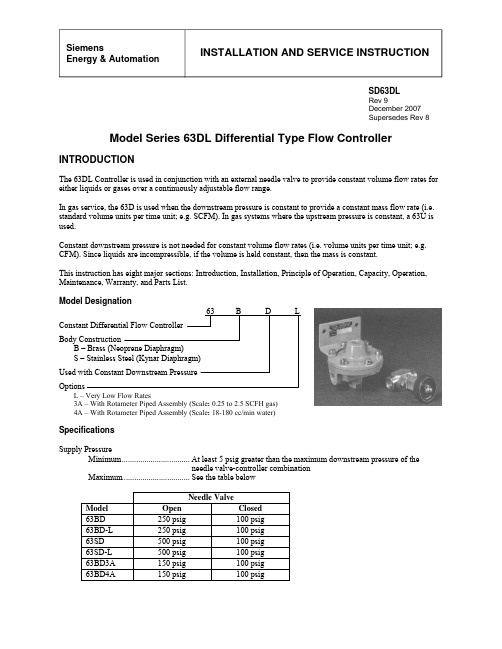
INSTALLATION AND SERVICE INSTRUCTIONSiemensEnergy & AutomationSD63DLRev 9December 2007Supersedes Rev 8Model Series 63DL Differential Type Flow ControllerINTRODUCTIONThe 63DL Controller is used in conjunction with an external needle valve to provide constant volume flow rates for either liquids or gases over a continuously adjustable flow range.In gas service, the 63D is used when the downstream pressure is constant to provide a constant mass flow rate (i.e. standard volume units per time unit; e.g. SCFM). In gas systems where the upstream pressure is constant, a 63U is used.Constant downstream pressure is not needed for constant volume flow rates (i.e. volume units per time unit; e.g. CFM). Since liquids are incompressible, if the volume is held constant, then the mass is constant.This instruction has eight major sections: Introduction, Installation, Principle of Operation, Capacity, Operation, Maintenance, Warranty, and Parts List.Model Designation 63 B D LConstant Differential Flow Controller Body Construction B – Brass (Neoprene Diaphragm) S – Stainless Steel (Kynar Diaphragm) Used with Constant Downstream Pressure OptionsL – Very Low Flow Rates3A – With Rotameter Piped Assembly (Scale : 0.25 to 2.5 SCFH gas)4A – With Rotameter Piped Assembly (Scale : 18-180 cc/min water)SpecificationsSupply PressureMinimum.................................At least 5 psig greater than the maximum downstream pressure of theneedle valve-controller combinationMaximum................................See the table belowNeedle Valve Model Open Closed 63BD 250 psig 100 psig 63BD-L 250 psig 100 psig 63SD 500 psig 100 psig 63SD-L 500 psig 100 psig 63BD3A 150 psig 100 psig 63BD4A 150 psig 100 psigSD63DLAmbient Temperature LimitsModels 63BD & 63BD-L........-40° to +180°F (-40° to +82°C)Models 63SD & 63SD-L.........-40° to +250°F (-40° to +120°C)Controller Differential...........................3.1 ±0.5 psig (others optional)INSTALLATIONShipping and StorageIf the controller is to be stocked, stored, or shipped to another location prior to piping, make sure that thefactory installed plastic plugs are in the ports to prevent entry of moisture, dirt, or other contaminants.MountingMounting dimensions and the locations and sizes of connections are shown on the installation drawing; see Figure 1. The controller may be mounted in any position. Install the needle valve and feedback connections as close to the controller as possible to minimize pressure drop between these points. The supply to the controller must be filtered to remove any solids.CAUTIONWhen installing the constant downstream controller, be sure the external needle valve isopen; see Figure 1. Failure to do this could result in applying a differential pressureacross the diaphragm of the flow controller in excess of its rate limit, thus causing thediaphragm to rupture.Blow out all piping before connections are made to prevent the possibility of dirt or chips entering the controller. Use pipe sealant sparingly, and then only on the male threads. A non-hardening sealant is strongly recommended. Connect the controller to a source of clean, dry, oil-free instrument air. See Instrument Air Requirements.CAUTIONExceeding the specified ambient temperature limits can adversely affect performanceand may cause damage to the controller.CAUTIONSupply pressure in excess of that stated in the Specifications section may cause damageto the controller.Instrument Air RequirementsConnect the instrument to a source of clean, dry, oil-free instrument air. Failure to do so will increase the possibility of a malfunction or a deviation from specified performance.CAUTIONthe suitability of this product for use with other process fluids, such as hazardous gases,except as listed on the appropriate certificate. Non-approved instruments are suitable foruse with instrument air only. Optional features and modifications such as tapped exhaust donot imply suitability for use with hazardous gases except as listed on the approvalcertificate.There are many types of synthetic compressor lubricants. Some may not be compatible with the materials used in construction of the instrument. Wetting of these materials by such an oil mist or vapor, etc., may cause them to deteriorate. This may ultimately result in failure of the positioner.SD63DLCAUTIONThe requirements for a quality instrument air supply can be found in the Instrument Society of America's "Quality Standard for Instrument Air" (ISA-S7.3). Basically, this standard calls for the following:Particle Size — Maximum particle size in the air stream at the instrument should be no larger than 3 microns.Dew Point — The dew point, at line pressure, should be at least 10°C (18°F) below the minimum temperature to which any part of the instrument air system is exposed at any season of the year. Under no circumstances should the dew point, at line pressure, exceed 2°C (35.6°F).Oil Content — Maximum total oil or hydrocarbon content, exclusive of non-condensable, should not exceed 1 ppm under normal operating conditions.Figure 1 Installation DimensionsSD63DLPRINCIPLE OF OPERATIONIf the pressure drop across a restriction is held constant, the volume flow through the restriction is constant; refer to Figure 2 on the next page. The needle valve (a variable restriction) can be set to an opening which will produce the desired flow rate. The pressure drop (∆P) across the needle valve is held constant by the flow controller as follows: 1.The differential spring and downstream pressure (P2) force the diaphragm and plunger down. The differentialspring produces a downforce equal to that produced by a constant pressure (K).2.The output pressure (P1) is applied to the needle valve and to the bottom of the controller’s diaphragm andforces the diaphragm and plunger up.3.The controller is in balance when the force due to P1 equals the forces due to P2 and K (i.e. P1= P2+K; P2=P1-K; and K=P1-P2). Since the pressure drop (∆P) across the needle valve equals P1-P2 and since P1-P2 equals K, then the pressure drop (∆P) must equal K; therefore flow is constant.Examples:P1 = P2+K P2 = P1-K K = P1-P2= 15+3 = 18-3 = 18-15= 18 psig = 15 psig = 3 psigFigure 2 SchematicCAPACITYThe formulas for the calculation of maximum and minimum flow rated can be found in Table 1.The minimum controllable flow will depend on the leakage past the valve plunger in the controller. It is, therefore, a function of the cleanliness of the valve and pressure drop across it as well as any inherent leakage. In general, for a standard flow controller, the maximum controllable flow will be approximately 1/100 of the maximum flow.OPERATIONWith the supply turned on, adjust the needle valve to obtain the desired flow rate, within the capacity of the controller.SD63DL Table 1 Flow Capacity FormulasSD63DLMAINTENANCEThe only maintenance normally required is to keep the valve plunger and external needle valve clean. Any change in the rate of flow for a given needle valve setting will probably be caused by partial clogging of the needle valve.CAUTIONFailure to obtain minimum flows will probable be caused by solids on the controller valve plunger. In the Model Series 63D, this may be removed for cleaning by unscrewing the retaining nut in the base of the controller and removing the valve plunger and spring (see Figure 3).A 63DL has a valve assembly which can be removed by first unscrewing the retaining nut in the base of the controller and then unscrewing the valve assembly. This assembly can be disassembled for cleaning by removing the snap ring fastened in the bottom of the valve port (see Figure 4).IMPORTANTThe valve port and plunger are paired through a lapping process and must not beinterchanged with other assemblies. Clean by washing in solvent. Do not use anyabrasives.Figure 3 Valve Plunger, Model Series 63D Figure 4 Valve Assembly, Model Series 63DLSD63DLCustomer/Product SupportThis section provides the Internet site addresses, e-mail addresses, telephonenumbers, and related information for customers to access Siemens product support.When contacting Siemens for support: •Please have complete product information at hand:• For hardware, this information is provided on the product nameplate (part number or model number, serial number, and/or version). •For most software, this information is given in the Help > About screen.•If there is a problem with product operation:• Is the problem intermittent or repeatable? What symptoms have been observed?• What steps, configuration changes, loop modifications, etc. were performed before the problem occurred?• What status messages, error messages, or LED indications are displayed? • What troubleshooting steps have been performed?•Is the installation environment (e.g. temperature, humidity) within the product’s specified operating parameters? For software, does the PC meet or exceed the minimum requirements (e.g. processor, memory, operating system)?•A copy of the product Service Instruction, User’s Manual or other technical literature should be at hand. The Siemens public Internet site (see the table) has current revisions of technical literature, in Portable Document Format, for downloading.• To send an instrument to Siemens for repair, request a Return Material Authorization (RMA).IMPORTANTAn instrument must be thoroughly cleaned (decontaminated) to remove any process materials, hazardous materials, or blood born pathogens prior to return for repair. Read and complete the Siemens RMA form(s).For customer/product support, visit the Siemens Process Instrumentation product support page at/Products/Process-Instrumentation/Support/Customer-Support.htm . Select the desired type of support (e.g. application, product selection, sales, technical – see below).Technical Support Telephone 180****7421 E-mail *************************** Hours of Operation 8 a.m. to 4:45 p.m. eastern time, Monday through Friday (except holidays) Technical Publications in PDF /Products/Process-Instrumentation/Support/PI-User-Manuals.htm then click the product line (e.g. Control Solutions) Public Internet Site /Products/Process-Instrumentation Repair Service 1 215 646 7400 extension 3187SD63DLWARRANTY(a) Seller warrants that on the date of shipment the goods are of the kind and quality described herein andare free of non-conformities in workmanship and material. This warranty does not apply to goodsdelivered by Seller but manufactured by others.(b) Buyer's exclusive remedy for a nonconformity in any item of the goods shall be the repair or the replacement (at Seller's option) of the item and any affected part of the goods. Seller’s obligation to repairor replace shall be in effect for a period of one (1) year from initial operation of the goods but not morethan eighteen (18) months from Seller’s shipment of the goods, provided Buyer has sent written noticewithin that period of time to Seller that the goods do not conform to the above warranty. Repaired and replacement parts shall be warranted for the remainder of the original period of notification set forth above,but in no event less than 12 months from repair or replacement. At its expense, Buyer shall remove andship to Seller any such nonconforming items and shall reinstall the repaired or replaced parts. Buyer shallgrant Seller access to the goods at all reasonable times in order for Seller to determine any nonconformityin the goods. Seller shall have the right of disposal of items replaced by it. If Seller is unable or unwillingto repair or replace, or if repair or replacement does not remedy the nonconformity, Seller and Buyer shall negotiate an equitable adjustment in the contract price, which may include a full refund of the contractprice for the nonconforming goods.(c) SELLER HEREBY DISCLAIMS ALL OTHER WARRANTIES, EXPRESS OR IMPLIED, EXCEPTTHAT OF TITLE. SPECIFICALLY, IT DISCLAIMS THE IMPLIED WARRANTIES OF MERCHANTABILITY, FITNESS FOR A PARTICULAR PURPOSE, COURSE OF DEALING ANDUSAGE OF TRADE.(d) Buyer and successors of Buyer are limited to the remedies specified in this article and shall have noothers for a nonconformity in the goods. Buyer agrees that these remedies provide Buyer and its successorswith a minimum adequate remedy and are their exclusive remedies, whether Buyer's or its successors’ remedies are based on contract, warranty, tort (including negligence), strict liability, indemnity, or anyother legal theory, and whether arising out of warranties, representations, instructions, installations, or non-conformities from any cause.(e) Note: The above does not apply to any software which may be furnished by Seller. In such cases, the attached Software License Addendum applies.Refer to the Customer/Product Support section of this manual for warranty and non-warranty service.All product designations may be trademarks or product names of Siemens Energy & Automation, Inc. or other supplier companies whose use by third parties for their own purposes could violate the rights of the owners.Siemens Energy & Automation, Inc. assumes no liability for errors or omissions in this document or for the application and use of information in this document. The information herein is subject to change without notice.Procedures in this document have been reviewed for compliance with applicable approval agency requirements and are considered sound practice. Neither Siemens Energy & Automation, Inc. nor these agencies are responsible for repairs made by the user.SD63DL PARTS LISTSiemens Flow Controller, Model 63BD-LDrawing 10671PLRev 5/87B/M - 10671S8IMPORTANTService Parts Kits are available for servicing the instrument. Contact Siemens for available kits; refer to the Product Support section of this instruction. Some parts in this Parts List may not be available for separate purchase.SD63DLPARTS LISTSiemens Flow Controller, Model 63SD-LDrawing 12047PLRev 5/87B/M – 12047S12IMPORTANTService Parts Kits are available for servicing the instrument. Contact Siemens for available kits; refer to the Product Support section of this instruction. Some parts in this Parts List may not be available for separate purchase.SD63DL PARTS LISTSiemens Flow Controller, Model 63BDDrawing 2881PLRev 5/87B/M – 2881S15IMPORTANTService Parts Kits are available for servicing the instrument. Contact Siemens for available kits; refer to the Product Support section of this instruction. Some parts in this Parts List may not be available for separate purchase.SD63DLPARTS LISTSiemens Flow Controller, Model 63SDDrawing 12042PLRev 5/87B/M – 12042S11IMPORTANTService Parts Kits are available for servicing the instrument. Contact Siemens for available kits; refer to the Product Support section of this instruction. Some parts in this Parts List may not be available for separate purchase.。
- 1、下载文档前请自行甄别文档内容的完整性,平台不提供额外的编辑、内容补充、找答案等附加服务。
- 2、"仅部分预览"的文档,不可在线预览部分如存在完整性等问题,可反馈申请退款(可完整预览的文档不适用该条件!)。
- 3、如文档侵犯您的权益,请联系客服反馈,我们会尽快为您处理(人工客服工作时间:9:00-18:30)。
控制器流量控制的说明书
控制器流量控制是一种用于管理和调节网络流量的技术。
通过控制
器流量控制,可以实现对网络中各个设备之间的传输速率进行合理分配,提高网络的资源利用率,优化网络性能,保障网络的稳定运行。
一、控制器流量控制的作用
控制器流量控制在网络管理中起到重要的作用。
它能够防止网络中
出现流量过载的情况,避免拥塞问题的发生,保障网络的稳定性。
同时,控制器流量控制还能通过对网络流量进行调度和分配,实现不同
设备之间的公平访问,提高网络服务质量。
二、控制器流量控制的原理
控制器流量控制主要依靠流控制器对网络中的流量进行监测和控制。
通过对网络中的数据流进行分析和判断,控制器流量控制可以根据预
设的策略和算法,对流量进行调度和控制。
其原理主要包括以下几个
方面:
1. 流量监测:控制器流量控制通过对网络中的流量进行实时监测,
获取网络中各个设备的传输情况和带宽利用率。
通过对流量的监测,
可以及时发现网络中的异常情况并采取相应的措施。
2. 流量调度:控制器流量控制能够根据事先设定的策略和算法,对
网络中的流量进行调度和分配。
通过合理地对流量进行调度,可以避
免网络中的拥塞问题,提高网络的性能和稳定性。
3. 流量控制:控制器流量控制可以对网络中的流量进行限制和控制。
通过对网络流量的控制,可以防止某些设备或应用占用过多的带宽资源,影响其他设备或应用的正常访问。
三、控制器流量控制的应用
控制器流量控制广泛应用于各种网络环境中,如数据中心、企业内网、云计算等。
它可以根据不同的网络需求和业务场景,灵活地实现
流量的管理和控制。
1. 数据中心:在数据中心中,控制器流量控制可以通过对服务器之
间的流量进行调度和控制,实现对数据中心网络的优化。
同时,它还
可以根据业务需求,对不同应用之间的流量进行分类和管理,提高数
据中心的服务质量。
2. 企业内网:在企业内网中,控制器流量控制可以通过对内部员工
的上网行为进行监控和控制,防止非法访问和滥用网络资源。
它还可
以对网络中的带宽进行合理分配,保证重要业务的流畅进行。
3. 云计算:在云计算环境中,控制器流量控制可以根据不同租户的
需求,对云端资源进行流量调度和控制。
通过合理地对云端流量进行
管理,可以确保云计算服务的可靠性和性能。
四、控制器流量控制的优势
控制器流量控制相比传统的流量控制技术具有许多优势:
1. 灵活性高:控制器流量控制通过软件定义网络(SDN)技术实现,可以根据不同的需求和网络环境进行灵活配置和调整。
2. 管理便捷:控制器流量控制可以集中管理整个网络中的流量,提
供可视化的管理界面,方便管理员对网络进行监控和管理。
3. 可编程性强:控制器流量控制允许网络管理员通过编写脚本和应
用程序,定制网络中流量控制的策略和算法,满足不同的业务需求。
4. 提高网络性能:控制器流量控制通过对网络流量进行优化和调度,可以提高网络的性能和资源利用率,提供更好的用户体验。
五、总结
控制器流量控制是一种重要的网络管理技术,通过对网络流量进行
监测和控制,可以实现对网络资源的合理分配和调度。
它在数据中心、企业内网、云计算等场景中具有广泛的应用前景。
随着网络技术的不
断发展,控制器流量控制将进一步完善和提升,为网络的快速发展提
供有力支持。