Servo Motor ID List (rev.2-GM)
SMC电机与驱动器组合说明书
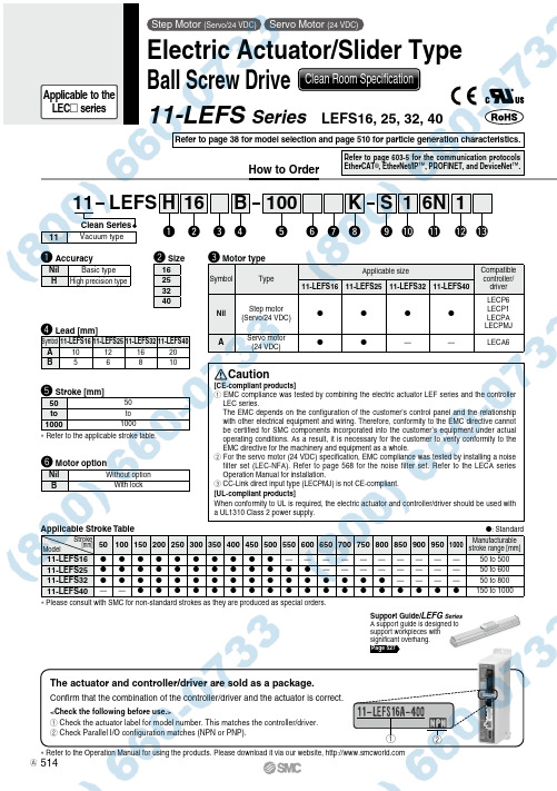
q w* Refer to the applicable stroke table.Confirm that the combination of the controller/driver and the actuator is correct.The actuator and controller/driver are sold as a package.<Check the following before use.>q Check the actuator label for model number. This matches the controller/driver.w Check Parallel I/O configuration matches (NPN or PNP).* Refer to the Operation Manual for using the products. Please download it via our website, [CE-compliant products]q EMC compliance was tested by combining the electric actuator LEF series and the controller LEC series.The EMC depends on the configuration of the customer’s control panel and the relationship with other electrical equipment and wiring. Therefore, conformity to the EMC directive cannot be certified for SMC components incorporated into the customer’s equipment under actual operating conditions. As a result, it is necessary for the customer to verify conformity to the EMC directive for the machinery and equipment as a whole.w For the servo motor (24 VDC) specification, EMC compliance was tested by installing a noise filter set (LEC-NFA). Refer to page 568 for the noise filter set. Refer to the LECA series Operation Manual for installation.e CC-Link direct input type (LECPMJ) is not CE-compliant.[UL-compliant products]When conformity to UL is required, the electric actuator and controller/driver should be used with a UL1310 Class 2 power supply.Clean Seriese Motor typer Lead [mm]t Stroke [mm]Cautionw Size16253240SymbolTypeApplicable sizeCompatible controller/driver 11-LEFS1611-LEFS2511-LEFS3211-LEFS40NilStep motor (Servo/24 VDC)VVVVLECP6LECP1LECPA LECPMJ A Servo motor (24 VDC)V V ——LECA65050to to 10001000Symbol 11-LEFS1611-LEFS2511-LEFS3211-LEFS40A10121620B 5681011Vacuum typeApplicable Stroke TableV : StandardStroke [mm]Model501001502002503003504004505005506006507007508008509009501000Manufacturablestroke range [mm]11-LEFS16V V V V V V V V V V——————————50 to 50011-LEFS25V V V V V V V V V V V V————————50 to 60011-LEFS32V V V V V V V V V V V V V V V V————50 to 80011-LEFS40——V V V V V V V V V V V V V V V V V V150 to 1000* Please consult with SMC for non-standard strokes as they are produced as special orders.Support Guide/LEFG Series A support guide is designed tosupport workpieces with significant overhang.Page 527q AccuracyNil Basic type HHigh precision typeStep Motor (Servo/24 VDC) Servo Motor (24 VDC)Electric Actuator/Slider Type Ball Screw Drive Clean Room Specification11-LEFS Series LEFS16, 25, 32, 40How to OrderRefer to page 38 for model selection and page 510 for particle generation characteristics.Refer to page 603-5 for the communication protocols EtherCAT ®, EtherNet/IP ™, PROFINET, and DeviceNet ™.11 LEFS 100B11S K6N 16we r tu y o i!0!1!2!3H q y Motor optionNil Without option BWith lock514Applicable to the LEC seriesAR: RightNil: Left* Produced upon receipt of order (Robotic cable only)Refer to the specifications Note 2) on pages 516 and 517.!0 Actuator cable length!3 Controller/Driver mounting* DIN rail is not included. Order it separately.o Actuator cable type *1u Vacuum port*1 The standard cable should be used on fixed parts. For using on moving parts, select the robotic cable.*2 Only available for the motor type “Step motor.”*3 Fix the motor cable protruding from the actuator to keep it unmovable. For details about fixing method, refer to Wiring/Cables in the Electric Actuators Precautions.*1 For details about controller/driver and compatible motor, refer to the compatible controller/driver below.*2 Only available for the motor type “Step motor.”*3 Not applicable to CE.*4 When pulse signals are open collector, order the current limiting resistor (LEC-PA-R-l ) on page 596 separately.!1 Controller/Driver type *1Compatible Controller/DriverTypeStep data input typeStep data input typeCC-Link direct input typeProgramless typePulse input typeSeries LECP6LECA6LECPMJLECP1LECPAFeatures Value (Step data) input Standard controllerCC-Link direct inputCapable of setting upoperation (step data) without using a PC or teaching boxOperation by pulse signals Compatible motorStep motor (Servo/24 VDC)Servo motor (24 VDC)Step motor (Servo/24 VDC)Max. number of step data 64 points14 points—Power supply voltage 24 VDCReference pagePage 560Page 560Page 600Page 576Page 590Nil Without controller/driver6N LECP6/LECA6(Step data input type)NPN 6P PNP 1N LECP1*2(Programless type)NPN 1P PNP MJ LECPMJ *2 *3(CC-Link direct input type)—AN LECPA *2 *4(Pulse input type)NPNAPPNPNil Left RRight Nil Without cable S Standard cable *2RRobotic cable (Flexible cable)*3Nil Screw mounting DDIN rail mounting *Nil Without cable1 1.5 m3 3 m 5 5 m 88 m*A 10 m *B 15 m *C20 m *!2 I/O cable length *1, Communication plug*1 When “Without controller/driver” is selected for controller/driver types, I/O cable cannot be selected. Refer to page 568 (For LECP6/LECA6), page 582 (For LECP1) or page 596 (For LECPA) if I/O cable is required.*2 When “Pulse input type” is selected for controller/driver types, pulse input usable only with differential. Only 1.5 m cables usable with open collector.*3 For the LECPMJ, only “Nil”, “S” and “T” are selectable since I/O cable is not included.Nil Without cable (Without communication plug connector)*31 1.5 m3 3 m *25 5 m *2S Straight type communication plug connector *3TT-branch type communication plug connector *3i Positioning pin holeNilHousing B bottom *Housing B bottomKBody bottom 2 locationsBody bottom* R efer to the body mounting example on page 114 for the mounting method.515Electric Actuator/Slider TypeBall Screw Drive11-LEFS SeriesStep Motor (Servo/24 VDC) Servo Motor (24 VDC)Clean Room SpecificationA。
HybridServoMotorDatasheet-AutomationtechInc

3
1.2°
3
Holding Torque
(N.m) 2.0
Phase Current
(A) 5.8
2
1.8°
4
8.0
6.0
Phase
Phase
Resistance Inductance
(Ohm) 0.62
(mH) 1.85
Rotor Inertia (g.cm2)
580
0.44
3.73
2580
Weight Encoder (Kg) (lines)
Hybrid Servo Motor
Cable Specifications
Model KL23-2N-1000
Standard Length 0.55±0.02m
Motor Cables
Extension
Length
Part Number
*
*
KL34-8N-1000
0.52±0.02m
*
*
*Contact us if you need motor extension cable.
/
Hybrid Servo Motor
KL34-8N-1000 Speed-Torque Curves
Figure 2: Speed Torque Curve of KL34-8N-1000
Note: These curves are based on 40% holding torque percentage of the drive. If higher torque at high speed is required, you can change the holding torque percentage to 100%. See software manual.
FESTO MTR-DCI智能 servo 电机单元说明书

Motor units MTR-DCI,intelligent servo motorsSubject to change –2011/072 Internet:/catalogue/...Motor units MTR-DCI,intelligent servo motorsKey features General informationThe motor unit MTR-DCI is an innovative motor with integrated power electronics for positioning tasks.Four components in one housing Integrated in the MTR-DCI are the motor,gear unit,controller and power electronics.This means that there is no need for a control cabinet or extensive cabling.ReliableThe integrated power electronics and controller removes the need for motor cables and improves the electromag-netic compatibility.Additionalmonitoring functions are integrated.UncomplicatedThe complete commissioning process can be performed directly on the MTR-DCI via the optional LCD display or on a PC via the user-friendly menus in the FCT (Festo Configuration Tool).No matter which approach is used,all parameters are continuously controlled.At a glance•Compact design•Smooth profile prevents the ingress of dirt•DC motor with planetary gear unit and encoder •Gear unit ratio:7:1;14:1,22:1•Protection class IP54Positioning functionality•16traversing records (including homing)•Constant acceleration and braking •Positioning controlProtective functions•Temperature monitoring •Current monitoring •Voltage failure detection •Following error monitoring •Software end-position detectionEasy actuation via •I/Ointerface •Profibus •CANopen •DeviceNet1Control panel with integrateddisplay (optional)2Input for reference limit switches 3RS232interface 4Operator interface:I/O interface 5Power supply 6Gear unit123456Typical applicationsAdjusting sorting conveyorsProgramming formats for paper or foil cuttingmachinesPROFIBUS ®,DeviceNet ®,CANopen ®is a registered trademark of its respective trademark holder in certain countries.2011/07–Subject to change 3Internet:/catalogue/...Motor units MTR-DCI,intelligent servo motorsType codesMTR–DCI–42S–VCSC–EG7–H2IOType MTRMotorMotor type Size Torque class SStandardNominal voltage VC 24V DC VD48V DCPlug design SCStraight plug outletMeasuring system EEncoderGear unit ratio G77:1G1414:1G2222:1Parameterisation interface R2RS232H2RS232and control panelElectrical connection technology IO I/O interfaceCO CANopen interface PB Profibus interface DNDeviceNet interfaceSubject to change –2011/074 Internet:/catalogue/...Motor units MTR-DCI,intelligent servo motorsTechnical data-N-Size32…62mm -P-Voltage 24,48V DCFieldbusinterfacesGeneral technical data Size32425262Rotary position generator Optical encoder No.of increments/revolution 300(1,200)1)500(2,000)1)Controller operating mode PWM MOSFET power amplifier Display resolution 128x 64pixelsType of mounting Can be bolted on or clamped to gearing unit flange Gearing unit type Planetary gearing Gear unit ratioG7 6.75(7:1);1-stage G1413.73(14:1);2-stage G22–22.21(22:1);2-stage1)Internal 4-fold evaluationElectrical data –Motor Size32425262Nominal voltage[V DC]24±10%48–10%/+5%Nominal current (motor)[A]0.7325 6.19Peak current [A] 2.1 3.87.720Motor constant[Ncm/A] 4.5 6.1 6.412.1Nominal power (motor)[W]1748122316Max.current (digital logic outputs)[mA]20060Parameterisation interface RS232;9,600baudMechanical data –Motor Size32425262Gear unit ratioG7G14G7G14G7G14G7G14G22Gearing unit output speed [rpm]481237444218444218504248153Gearing unit torsional backlash [°]≤1.9≤1.55≤1.3≤0.95≤1.1≤0.75≤1≤1.5≤1.5Gearing unit output torque [Nm]0.150.290.59 1.13 1.62 3.08 3.787.211.66Gearing unit efficiency 0.750.70.80.750.80.750.80.750.75Mass moment of inertia (rotor)[kg cm 2]0.0240.323 1.209 3.3Mass moment of inertia (gearing unit)[kg cm 2]0.000890.001490.002350.004410.011320.017110.0170.0350.022Radial shaft load [N]4070160230200320240360360Axial shaft load [N]1020508060100507070Product weight[kg]0.720.741.721.833.13.37.68.08.02011/07–Subject to change 5Internet:/catalogue/...Motor units MTR-DCI,intelligent servo motorsTechnical dataOperating and environmental conditions Size32425262Digital logic outputsNot electrically isolated Electrically isolated Insulation protection class to VDE 60034F Protection class IP54Protective functionsI 2T monitoringFollowing error monitoring Software end position detection Voltage failure detection Current monitoringTemperature monitoring:Silicon absolute temperature sensor,switches off at temperatures >70°C Ambient temperature [°C]0...+50Storage temperature [°C]–25...+60Relative air humidity [%]0...95(non-condensing)CE mark (see declaration of conformity)In accordance with EU EMC directive CertificationC-TickNote on materials Contains paint wetting impairment substancesMaterials Motor unit housing Anodised aluminiumMotor unit coverAluminium,precision casting,coated (size 62milled)Technical data –I/O/fieldbus interface Type MTR-DCI- (I)MTR-DCI-…-CO MTR-DCI-…-PB MTR-DCI-…-DN InterfaceI/O interface for 15travers-ing records and homing CANopenProfibus DPDeviceNet Number of digital logic inputs 6–––Number of digital logic outputs 2–––Max.current of digital logic outputs (size)32/42200–––52/6260–––Bus terminating resistor 1)–Not integrated in the deviceNot integrated in the deviceNot integrated in the device Communication profile –DS301/FHPP DP-V0/V1/FHPPFHPP–DS301;DSP402Step7functional modules Device type 0C h Max.fieldbus baud rate[kbps]–1,00012,0005001)Details of bus terminating resistor 10Subject to change –2011/076 Internet:/catalogue/...Motor units MTR-DCI,intelligent servo motorsTechnical dataTorque M as a function of rotational speed n Size 32Size42M [Nm]n [r p m ]n [r p m ]M[Nm]Size 52Size 62n [r p m]M[Nm]M [Nm]n [r p m ]Gear unit ratio 7:1Gear unit ratio 14:1Gear unit ratio 22:11Torque,nom.2Torque,max.3Torque,nom.4Torque,max.5Torque,nom.6Torque,max.2011/07–Subject to change 7Internet:/catalogue/...Motor units MTR-DCI,intelligent servo motorsTechnical data Pin allocation1Reference switch,3-pin M8socket 2RS 232interface,4-pin M8socket Pin Function Pin Function 124V10V4Reference input 2Transmitted data (TxD)30V3Received data (RxD)–4–3I/O interface,9-pin Sub-D plug 3CANopen interface,9-pin Sub-D plug Pin Function Pin Function 1Traversing record coding,bit 01–2Traversing record coding,bit 12CAN_L 3Traversing record coding,bit 23CAN_GND 4Traversing record coding,bit 34–5Start bit 5CAN_SHLD 6Enable bit6CAN_V–7Ready signal output 7CAN_H 8MC signal output 8–90V9CAN_V+3Profibus interface,9-pin Sub-D socket 3DeviceNet interface,9-pin Sub-D plug Pin Function Pin Function 1–1–2Logic_GND 2CAN_L 3RxD/TxD-P 3CAN_GND 4CNTR-P 4–5DGND 5CAN_SHLD 6VP6CAN_V–7Logic_V (24V DC)7CAN_H 8RxD/TxD-N 8–9–9CAN_V+4Power supply,2-pin plug Pin Function 124V DC (for MTR-DCI-32/42/52),48V DC (for MTR-DCI-62)20V–––––––Subject to change –2011/078 Internet:/catalogue/...Motor units MTR-DCI,intelligent servo motorsTechnical dataTypeD1∅g10D2∅±0.1D3∅h8D4∅h7D5∅H1L1±1L2±1L3L4L5L6T1T2+2MTR-DCI-32S-…-G7––21.56–13±0.2175.5–18.7±0.6 2.5±0.3––6–MTR-DCI-32S-…-G14––21.56–13±0.2175.5–18.7±0.6 2.5±0.3––6–MTR-DCI-42S-…-G7*******–1117633.325±12±0.125–7+210MTR-DCI-42S-…-G144242258–1117646.325±12±0.125–7+210MTR-DCI-52S-…-G752523212–17.31943933±13±0.331–10–MTR-DCI-52S-…-G1452523212–17.31945333±13±0.331–10–MTR-DCI-62S-…-G7626240141561.32704739±15±0.331.3910–MTR-DCI-62S-…-G14626240141561.32704739±15±0.331.3910–MTR-DCI-62S-…-G22626240141561.32704739±15±0.331.3910–2011/07–Subject to change9Internet:/catalogue/...Motor units MTR-DCI,intelligent servo motorsOrdering data –Modular products Mandatory data 0M Module No.Motor unitFlange/sizeNominal voltageMeasuring systemParameterisationinterfaceMotor type Torque class Plug design Gearing unitElectrical connection technology 533736533742533748533754MTR DCI32425262SVC VDSC EG7G14G22R2H2IO CO PB DNOrder example 533742MTR –DCI –42S –VC SC –E G7–R2IOOrdering table Size32425262Condi-tionsCodeEnter code 0M Module No.533736533742533748533754Motor unitMotor unitMTR MTR Motor type DC servo motor with integrated position controller -DCI -DCI Flange/size 32425262-…Torque class Standard torque class S SNominal voltage[V]24DC –-VC [V]–48DC-VD Plug designStraight plug SC SC Measuring system Encoder-E -EGearing unitIntegrated planetary gearing i =6.75G7Integrated planetary gearing i =13.73G14–Integrated planetary gearing i =22.21G22Parameterisation interface RS232interface-R2RS232interface +control panel -H2Electrical connection technologyI/O interface IO CANopen CO Profibus DP PB DeviceNetDNTransfer order codeMTR–DCI S SC –E ––PROFIBUS ®,DeviceNet ®,CANopen ®is a registered trademark of its respective trademark holder in certain countries.Subject to change –2011/0710 Internet:/catalogue/...Motor units MTR-DCI,intelligent servo motorsAccessories2011/07–Subject to change11Internet:/catalogue/...Motor units MTR-DCI,intelligent servo motorsAccessories1)User documentation in paper form is not included in the scope of delivery。
AX5000 NCT入门指南说明书

How to use Beckhoff AX5000servo drive withNCT CNC controllerGetting Started GuideThe NCT ltd.does not provide direct support to interface non-NCT produced EtherCAT devices(including AX5000servo drives)with the NCT3xx CNC controller.If you have intention of using other manufacturers'EtherCAT devices,please get contact with NCT ltd.This user guide’s purpose to give a step-by-step guide to set up the EtherCAT communication between a Beckhoff AX5000servo drive and NCT3xx CNC controller.We assume basic knowledge about EtherCAT and the NCT3xx controller.The Beckoff’s TwinCAT software contains the Drive Manager which provides a comprehensive interface to do all settings of an AX5000servo drive.Best practice to set up a basic setting through TwinCAT’s Drive Manager,export the parameters from TwinCAT and then import these parameters into the NCT3xx CNC controller.1.Provide the xml description to AX5000All EtherCAT devices should have a valid xml description,which is a file in xml format.You should download your AX5000’s xml description form Beckhoff homepage and copy them into the TwinCAT’s TwinCAT\Io\EtherCAT directory.You can copy all files what you extracted from the downloaded zip file. In case of TwinCAT3you can use the“Update Device Descriptions(via ETG Website)…”function.2.Connect the AX5000to the TwinCAT running PCAccording the AX5000’s user guide set up and switch on the servo drive and connect the motor and the encoder too.Connect the servo drive to the TwinCAT running PC via an Ethernet cable.Scan for devices:If the motor is from Beckhoff too,the TwinCAT Drive Manager can read the motor type form encoder, and after device scanning immediately ask us if we want to use this function.If the motor is not form Beckhoff,but the Drive Manager’s motor parameter collection(Motorpool)contains it,we can select it from this list.Now let’s the TwinCAT Drive Manager to identify the connected servo drive and the motor type.If TwinCAT has found your drive,you will see it under the“Device1(EtherCAT)”in the device list. After a successful identification open the Drive Manager and check the servo drive and motor type, they should be same as the drive and motor name plate.You can find the servo drive description parameters in the Drive Manager under the Device element.You can see the identified motor and encoder type under Channel A/B on the Motor and feedback tab.If the identification was not successful on this tab you can select the motor and the encoder if the Drive Manager’s database contains your motor/encoder configuration.In case of two axes servo drive(i.e.AX52xx)the TwinCAT refers Axis1as Channel A and Axis2as Channel B.Check the motor type on both channel.3.Check and set the drive parametersYou should check all the parameters and change them according you application requirements if it needed.You can do it by stepping one-by-one on the Tree items.If the drive is a two axes servo drive you can find the axis1and2parameters under the Channel A and Channel BThe NCT3xx CNC controller uses the drives in velocity control mode by default,we can change this under the Channel/Configuration/Process data/Operation mode.Change the configured operation mode the SetValue S-0-0032Primary operation mode parameter to2.velo control.Select MDT and remove with<<button the S-0-0047Position command value item from the process data parameter list,and add with the>>button the S-0-0036Velocity command value.We do not need to make further process data settings,because these settings are not part of the exported parameters and we should do the PDO setting on the NCT controller again.If the drive is a two channel drive you should do this setting on both channel.4.Check and export parametersWe check if the drive accepts the parameters.Switch on the Freerun mode,select the Online tab and change the EtherCAT state to Op.If the drive changed its state to Op(there is Op in the Current state box)we can export the parameters. Select the Startup tab,right click and choose“Export to xml...”.If the drive is a two axes drive the exported parameter list will contain both axis’parameters.5.Set up the AX5000on NCT3xx controllerCopy the AX5000’xml description to NCT3xx controller.Open the EtherCAT window from Softkey strip(Service->ECAT Config),and use the EtherCAT window’s XML Import function.You need import only the Beckhoff AX5xxx.xml file,no other files needed.Switch on and connect the AX5000servo drive to the NCT3xx controller with an EtherCAT cable. After pressing AutoScan the drive should show up in the device list with an icon and with a correct device name.On the Online tab you should see the device is in PreOp state.Select the SoE tab and you can see the drive parameters.The tab contains on the top a State line which shows the current state of the drive or an error message in case of error.At the end of this line there is the Clear button which performs an error clear.In case of two axes drive you will see the axis selector,where you can choose which axis’parameters want to see.To import the parameters click on Import button,and select All files(*.*)to see the TwinCAT parameter list file,which has xml extension,and open the previously exported xml file.The import process should go without any error.If you have a two axes drive first select channel A import the file, then select channel B and import the same file,because only parameters are imported which are related to the currently selected axis.In case of error check first the TwinCAT2StartupXML.xsd file,it should be in the Config/XML directory and needed to process the TwinCAT xml format.After importing parameters open the Startup tab,and you should see the newly imported parameters with their values.In case of two axes drive you should see the parameters both form channel A and B.You should change some parameters before you enable the drive.First set the AX5000’s S-0-0001 Control unit cycle time(TNcyc)and S-0-0002Communication cycle time(tScyc)parameters to the the NCT3xx controller cycle time.For example if the controllers cycle time1ms,you should set these parameters to1000,which is the cycle time in microsec.You can change the parameter values either on Startup tab or on SoE tab,because the SoE parameter modifications will change the value on startup too(if the parameter is already on startup). In case of two axes servo drive be sure that the S-0-0001and S-0-0002parameters are only once on startup list and they are assigned to channel A.Check the S-0-0032Primary operation mode parameter, it’s value should be2(velocity control mode),if your drive is a two axes drive check this parameter on both channel.According to the selected velocity operation mode,you should change the process data settings too,because these settings are not part of the parameter list which was exported from TwinCAT. Switch to PDO Settings tab,select Outputs form the Device SM list,after that select MDT and remove with<<button the S-0-0047Position command value item from the process data parameter list,and add with the>>button the S-0-0036Velocity command value.If the drive is a two channel drive you will see in PDO Assignment list MDT1and MDT2and should do this setting on both channel.Check drive EtherCAT state on Online tab,it should be in PreOp state and NoError.Check the drive errors on SoE tab,and try to clear the error is there is any.If you have a two axes drive the State line always shows the selected axis’state,and the Clear button will perform the error clear on the selected axis as well.Now you can press Set Config on the softkey and check if the drive reaches he Operational(OP) state.In case of initialization error check the error box on the Online tab.If it contains ErrorSOE value, you can see the parameters which value are incorrect or inconsistent on the S-0-0021IDN-list of invalid operation data for CP2.The State line on SoE tab and the drive’s display could give you information about the cause of the error.If the drive reached the Operational state,switch to PDO tab and you can see all the process data variables with their values witch are refreshed cyclically.Now the basic properties of the drive and motor are checkable(value of the Drive status word;is the Position feedback value counting if the motor shaft is rotated manually,etc.).In case of two axes drive the process data IDNs ending with “(A)”and“(B)”are related to axis1and axis2,respectively.At this point you have the option to enable the drive manually through the S-0-0134Master control word and the give speed set value through the S-0-0036Velocity command value.The output PDO variables of the EtherCAT devices on the PDO tab are write protected by default,so you shouldswitch the drive to Offline mode on PDO tab.The Offline mode detaches the drive’s output PDO variables from the NC/PLC,so you can write the drive PDO variables directly.The Offline mode enables you to check the communication and basic functions without the NC/PLC,but because of safety reasons in general not recommended to use it.If you decide to move the motor in Offline mode,be very careful because there is no NC/PLC protection,and the motor will move according to value what you give on the PDO tab.In this case always be sure about the motor is firmly fixed,can rotate freely and you can safely disconnect the drive’s main power supply if needed!You can map these process data variables to NC and PLC symbols by means of Settings2tab.On the Settings2tab you can see all the input and output process data variables of the drive.Select a variable,click on Link button and select the symbol what you want to assign to the PDO variable.If there is length mismatch between the drive’s PDO variable and the CNC symbol,the mapping will be denied and the Offset window will appear,where you can adjust the length and bit offset properties of the assignment.You can delete the connection between drive variable and the NC symbol by the X button.The picture above shows an example mapping of a Beckhoff AX5206two channel servo drive, where the PDO variables of channel A are assigned to NC drive2and the variables of channel B are assigned to NC drive3In this user guide we showed how can you import the base parameters form TwinCAT into the NCT3xx CNC controller and set up the EtherCAT communication between the controller and the AX5000servo drive.。
AMKASYN AC Servo和主轴电机:一般技术数据说明书

AMKASYNAC Servo and Main Spindle MotorsGeneral technical dataVersion: Part-No.: 2002/22 27853About this documentationName: PDK_027853_Motoren_Uebersicht_enWhat has changed:Copyright notice: © AMK GmbH & Co. KGCopying, communicating, and using the contents of this documentation is not permitted,unless otherwise expressed. Offenders are liable to the payment of damages. All rights arereserved in the event of the grant of a patent or the registration of a utility model or design.Reservation: We reserve the right to modify the content of the documentation as well as to the deliveryoptions for the product.Publisher: AMK Arnold Müller Antriebs- und Steuerungstechnik GmbH & Co. KGGaußstraße 37 – 39,73230 Kirchheim/TeckTel.: 07021/5005-0,Fax: 07021/5005-176E-Mail:********************Dr.h.c. Arnold Müller, Eberhard A.Müller, Dr. Günther VogtRegistergericht Stuttgart HRB 231283; HRA 230681Service: Phone: +49/(0)7021 / 5005-191, Fax -193Office hours: Mo-Fr 7.30 - 16.30, on weekends and holidays, the telephone number of theon-call service is provided through an answering machine. .You can assist us in finding a fast and reliable solution for the malfunction by providing ourservice personnel with the followingInformation located on the ID plate of the devicesthe software versionthe device setup and applicationthe type of malfunction, suspected cause of failurethe diagnostic messages (error messages)Internet address: www.amk-antriebe.deContent1 AMKASYN Motor Series DS, DV, DH and DW 41.1 Short description 42 General technical data 53 Technical Data Holding brake and External fan 63.1 Holding brake 63.2 External fan 64 Motor connection 74.1 Terminal box types and terminal block wiring 74.2 Connector types 84.3 Dimensions of the motor connector and connection wiring 85 Motor encoders 106 Abbreviations 127 Important notes 138 AMK Motor type codes 141 AMKASYN Motor Series DS, DV, DH and DW1.1 Short descriptionThe AMKASYN series of motors consits of the compact, highly dynamic AC-servo motor types DS and DV as well as the heavy-duty AC main spindle motor types DH and DW with high power density and precision balanced rotors.The AMKASYN motors are optimally tuned to be used with the AMKASYN digital AC-servo inverters for multi-motor applications in the power range of 1.3 to 75 kVA and with the AMKASYN digital compact servo drive in the power range of 0.7 to 50 kVA. Together the motors and inverters form an intelligent, digital drive system for servo and main spindle applications, which satisfies every demand.Advantages of the AMKASYN motor series Maintenance-freeSturdyPowerfulCompactHigh efficiencyOptimum power to weight ratiohighly dynamic responseHigh overload capacityWinding temperature sensors asprotection against overloadIntegrated encoder for speed andposition controlAreas of applicationThe AMKASYN motors are especially suitable for use as servo and main drive motors in: Plant construtionElevator technologyPrinting machinesWoodworking machinesPlastic processing machinesWarehousing and conveyortechnologyTest standsProcess engineeringTextile machinesPackaging machinesMachine tools2 General technical dataAmbient temperature: +5 ... +40°C / 94°F. At higher ambient temperatures up to maximum 60°C / 140°F the ratingdata must be reduced by 1% per 1° Kelvin temperature rise.Installation altitude: Up to 1000m / 3281ft above sea level. In operation above 1000m / 3281ft altitude, ambienttemperatures corresponding to DIN VDE 0530 table 4 shall be used as basis.Humidity: Maximum 85% relative humidity, non-condensating.Degree of protection: IP 54. Higher degree of protection on request.The stated maximum speeds apply for the IP 54 version with seal ring.Rating data: Refer to 100 Kelvin temperature rise in the windings. The test motor is mounted using athermally insulating flange.Insulating material class: F according to DIN VDE 0530.Thermal protection: PTC resistor, cold resistance approx. 150-800 Ω.Bearings: Ball bearings, lifetime lubricated.Axial eccentricity run-out: N according to DIN 42955.Balancing grade: G 2,5 corresponding to VDI 2056.Vibrational grade: N according to DIN ISO 2373.Painting: RAL 9005, flatt black.Cooling: Non-ventilated or fan-cooled; airflow toward output shaft. Reverse airflow as option.3 Technical Data Holding brake and External fan 3.1 Holding brakeThe motors can be equipped optionally with holding brakes. These are not suitable as service brakes. The brakes are lifted with 24V DC input. In the case of changed operating conditions, the operating instructions of the brake manufacturer must beobserved.For the maximum speed of the motor the maximum speed of the brake must also be considered.3.2 External fan4 Motor connectionDV, DH and DW motors feature terminal box connections for motor leads, fan and holding brake. The motors of the DS series and optionally of the DV series feature plug-style connectors. Connection cables with the corresponding cross-sections can be purchased preassembled.Shielded cables must be used for EMC reasons.* The current values IL for the connection cable refer to applications according to EN 60204-1:1992 in the cable laying type B2, or according to DIN 46200 for connection bolts.KG 1and KG 3 KG 4 and KG 5Picture name: ZCH_Motoren_Klemmkasten4.2 Connector types* The current values IL for the connection cable refer to applications according to EN 60204-1: 1992 in the cable laying type B24.3 Dimensions of the motor connector and connection wiringConnector pin designation is true for view on to the motor connector socket in each case. Power connection size BG 1picture name: ZCH_Motoren_Leistungsstecker1.0picture name: ZCH_Motoren_Leistungsstecker1.0_querPower connection size BG 1,5picture name: ZCH_Motoren_Leistungsstecker1,5picture name: ZCH_Motoren_Leistungsstecker1.5_querSocket and connector for external fanpicture name: ZCH_Motoren_Einbaudosepicture name: ZCH_Motoren_Anschlussstecker5 Motor encodersThe motors are equipped with one of these encoders.The motor maximum speed can be limited additionally by the encoder !picture name: ZCH_Motoren_Einbausteckdose_MotorgeberSignal description6 AbbreviationsMotor tables Holding brakeCharacter Unit Description Character Unit DescriptionM0Nm Zero speed torque M Br Nm Holding torqueM N Nm Rated torque n maxBR1/min Brake maximum speed P N kW Rated power U Br V Rated voltage 24V ≅n N 1/min rated speed (unregulated)n F1/min speed limit for constant rated power I BrJ Br Akgm2Brake rated currentBrake moment of interian max 1/min Maximum speed m Br kg Weight of the brake, total U N V Rated voltage motor weight is m + M BR I N A Rated currentJ kgm2 Rotor inertiam kg Motor weightkT Nm/A torque constant(M=I*kT) External fanQ I/min Rated flow rate Character Unit DescriptionΔT K Temperature rise of the liquid atpoint of rated operation U FI FVAExternal fan rated voltageExternal fan rated currentL Br mm Length of motor including brakeL1 Br mm Length of fan cooled motor includingbrake7 Important notesMotors can reach surface temperatures above 100°C / 212°F during operation. Before touching the motor check the surface temperature to avoid injury.In the case of motors with keyways and freely rotating shaft ends, the key must be removed or secured against being thrown off.Before opening the terminal box or pulling out or plugging in a connector on the motors, ensure that there is no voltage at the termination end. Voltage can be present a the connections even when the motor is not moving. If not complied with injuries or death may occur.A low-resistance connection of the motor housing to the PE ground bus in the control cabinet is required for trouble freeand safe operation of the motors.Pounding or uncontrolled impact of force onto the motor shaft during transport, storage and installation of the motors in the machine can lead to damage of the bearings and shaft.Inadmissible axial and radial loads lead to reduction of the bearing life. Bearing load diagrams are available on request.When using couplings, attention to correct assembly of the coupling components has to be observed. Alignment errors or offset of the coupling can lead to premature destruction of bearings and of the coupling.All motors listed may not be connected directly to the main power lines. The motors are intended exclusively foroperation on AMK inverter systems.8 AMK Motor type codespicture name: ZCH_Motoren_Typenschluessel_DVAMK Arnold Müller GmbH & Co. KG Antriebs- und Steuerungstechnik Gaußstrasse 37-3973230 Kirchheim/Teck DEUTSCHLANDTelefon: +49 (0) 70 21 / 50 05-0 Telefax: +49 (0) 70 21 / 50 05-199 ********************www.amk-antriebe.de。
Mitsubishi MR-C Servo:微型迷你舵机说明书
MR-C ServoSERVOMOTORS &LIFIERS Cost Effective Micro-Servo1Actual Size Small,Easy-to-Use,High-Performance.An Extraordinarily Compact,Intelligent Servo.The MELSERVO-C brushless servo,in a handy super-compact size,is the culmination of Mitsubishi servo technology.The servo amplifier achieves high performance in an unprecedented compact body, only 40 millimeters wide and 130 millimeters tall.Small but powerful, it comes equipped with a serial encoder, and is packed with high-level features, including real-time auto-tuning and model adaptive control.This servo can substitute for microstep and five-phase stepping motors, and it can be easily used even by first-time users.A “new age”servo for use in a broad range of fresh applications, including semiconductor manufacturing devices, printing machines and electronic component assembly.2Handy Super-Compact Sizes Servo Amplifier•For up to 400 watts, a super-compact size of only 40 millimeters by 130 millimeters was achieved through the incorporation of a newly developed power module and an optimal thermal design made possible with computer-aided engineering techniques.•Mitsubishi servo control technology including model adaptive control and real-time auto-tuning is achieved with a micro-controller, resulting in the maximum performance with the fewest number of parts.•Select either a single-phase 100 V or 200 V amplifier.s Servomotor•Improved heat dissipation of the motor and a super-compact design were achieved with a molding process that uses newly developedhigh-thermal conductivity resin.(Frame diameter on 100-watt and below units is 40 millimeters square.)•This compact design offers maximum torque of 400% (100-watt and below units) through enhanced coil density made possible through original Mitsubishi technology.•Motors with failsafe electro-magnetic brakes are available.Stepping Motor Replacements No More Cogging or StallingBecause control is performed using integral feedback to verify the servomotor’s position, this unit can start smoothly, without losing step.This is often a problem with stepping motors responding to sudden load fluctuations and sudden acceleration /deceleration.s Smooth OperationOperation is smooth at low speeds and duringacceleration /deceleration because feedback control is performed with a 4,000 pulse /rev encoder.s Stable Torque CharacteristicsReduced machine cycle time and greater production speeds are achieved thanks to stable torque characteristics, from low to high-speeds (maximum rotation speed 4,500 rpm).s Controllable TorquePrevent damage to machines and products by using the torque-limiting feature.Move Up to the Next Level Now010002000300040004500TorqueIntermittent RatingStepping MotorContinuous RatingServomotorRotation Speed (rpm)0-0-Positioning CommandStepping MotorControllerFeedbackServomotorControllerPositioning CommandOpen-Loop ControlStepping MotorSpeed Waveform at 10 rpmServomotorSpeed Waveform at 10 rpmFeedback ControlComparison of Stepping Motor and Servomotor T orque Speed CurvesEasy Operations Real-Time Auto-TuningMerely selecting the response setting that fits themachine being used eliminates the need for servo gain adjustments.This is because the real-time auto-tuning function automatically adjusts the gain to fit themachine.And Mitsubishi’s unique control technology model adaptive control makes possible a highly responsive and stable system.s Automatic Recognition of Motor ModelThe servo amplifier automatically recognizes the drive motor with the motor ID information (motor model name, etc.) built into the encoder.This eliminates the need to set parameters, thereby removing setting errors as well.s Easy Operation•T est operation, monitoring, and parameter setting can all be performed easily using just four buttons.•The monitoring function allows you to display the status of nine parameters, including motor rotation speed, feedback pulse, command pulse, effective load factor, and peak load factor.•The servo can remember the conditions that existed during the last four alarms.•Either a 24 V or 5 V power supply can be selected for the I/O that can be user assignable.•The MR-C can handle three command pulseformats:encoder signals, pulse and direction and CW /CCW pulses.Satisfies Overseas Industrial Standardss Satisfies EN,UL,and cUL Standards•An EMC filter (optional) is available for meeting EN-standard EMC directives.The MR-C-UE servo amps and HC-PQ-UE servomotors meet low-voltage directives (LVD).•The MR-C-UE servo amps and HC-PQ-UE servomotors meet UL, cUL and EC standards.Personal Computer Interfaces Communication with a PC is Made Possible •This servo can be connected to a PC using the optional RS-232C unit.•Setup software can be used to display various monitoring details and to enter and save all parameters.And with its graphing functions, it is possible to display servomotor speed, torque waveform, and digital I/O status.Thismakes it possible to check operating conditions.3q Speed response frequency characteristics 200Frequency Gain (dB)(Hz )Speed Response Frequency CharacteristicsEncoder Serial CommunicationsDisplay Panel and Operation ButtonsGraph Display WindowParameter Display WindowSerial Communications •Feedback Pulse •Motor Capacity •Magnetic Pole Detection•Alarm InformationApplicationsSemiconductorManufacturing Devices The MR-C can be used to replace stepping motors in LCD and wafer conveyance devices.Electronic Component AssemblyCan be used with small loaders and unloaders and simple X-Y positioning tables.RobotsSuited for use at the tips of small and ultra-compact robots.Printing Machines Well suited for use in positioning for registration presses and label printing.Textile Machines Well suited for use in positioning with knitting, embroidering,and laundry machines.Other Applications The MR-C can be used to replace microstepping and five-phase step motors in office, medical andexperimental machinery.s Specifications (Those inside parentheses are not available with the MR-C.)Function DescriptionMonitoring Comprehensive display, high-speed display, graphingAlarm Alarm display, alarm history, (alarm data display), (pre-alarm graph display)Diagnosis DI /DO display, (display of reasons for failure to rotate), (time setting display), (cumulative power on display), software number display, tuning data display, (ABS data display), (VC automatic offset display)Parameters Data setting, list display, list display of changes, detailed information display, (feed method selection [note 2])Test Operation JOG operation, (positioning operation), (motor-less operation), DO forced output, (programmed operation through simplified language), (one-step feed [note 2])Point Data [note 2](Comprehensive position /speed block data display, data setting, teaching function)File Management Data entry/saving, printingOther Functions(Automatic operation), help displaysMCOMM Configuration SoftwareWith this software everything from setup to monitoring, diagnostics, parameter entryand recall, and test operation can be performed easily with a personal computer.To use this software, the optional RS-232C unit must be attached to the servo amplifier.Version 21 and above can be used with the MR-C series.sFeatures•Windows 3.1,Windows 95 CompatibleCompatible with PCs running Microsoft Windows 3.1 (note 1),Windows 95.Setup can be performed with a PC.Required memory:4MB (more recommended)Required hard disk space:1MB (more recommended)Serial port required•Wide Range of Monitoring FunctionsEquipped with graphing functions capable of displaying servomotor status through input signal triggers, such as command pulse, standing pulse, and rotation speed.•PC Test OperationServomotor test operation can be performed easily with a PC.6Notes:1.Windows is a trademark of the Microsoft Corporation.2.Available with MR-H-AC.3.This software may not operate properly on all personal computers.4MCNFBL1L2PCUVWConnections between the MR-C and peripheral equipment.Required connectors and options have been listed to allow usersto set up their systems and use immediately after purchase.Connections with Peripheral EquipmentDisplay PanelDisplays alarms, parameterand system function values.(See page 7)Setting SectionParameters, system functions,and modes are selected and setwith push buttons.(See page 7)Power SupplySingle-Phase 100 V or 200 V Power Supply(Power Supply and Voltage Vary Depending on the Series)MR-C Servo AmplifierMR-C A or MR-C A1Twist to Less than 10 MetersConnector for encoder feedback.CN2 Magnetic Contactor (MC)Used to turn off the servo amplifier’s powerwhen an alarm has been triggered.Models:S-N18,S-N21(See manual)Optional Regeneration UnitAttached as necessary whenregeneration frequency is high orload’s moment of inertia is large.Models:MR-RB013, MR-RB033(See manual)No-Fuse Circuit Breaker (NFB)Used to protect the power supply line.Models:NF30 type A for:MR-C10A,MR-C10A1 and MR-C2OANF30 type 10A for:MR-C20A1and MR-C40A(See manual)5MR-TB20Junction Terminal BlockSignals can be easily wired to the optional terminal block and optional CN1 cable.MR-C-TO1Optional RS232-C UnitMounting this optional unit on the underside of the servo amplifier makes RS-232C communications possible.Turn the power off when mounting or removing this unit.U V WControl signal connector.(See manual)Upper ControllerThis servo can be connected to a Mitsubishi motion controller or any pulse output controller.External 24 V or 5 V Power SupplyConnects to an external power supply.(24 or 5 volts, 0.2 amperes or greater)Encoder CableThis cable connects the servomotor encoder to the servo amplifier.Extended-life cables with a long bending life are also available.This cable comes in standard lengths of 5 and 10 meters.Models:MR-JCCBL s M-L (Standard model)MR-JCCBL s M-H (Extended-life model) (See manual)EncoderDetects position, speed and magnetic pole position.Terminal BlockThe power supply, optional regeneration unit, and motor’s U, V , W ground wires are connected to the terminal e a regular flat head screwdriver to connect the power supply to the terminal block.(See manual)Servomotor CableThe motor’s power cable and theencoder cable are extended 0.3 meter.CN1CN3RS-232C Communications (CN3)Connects the unit to user’s personal computer, making possible monitoring, batch parameter entry and storage, graph display,and test operation.Dedicated cables and setup software are available also.Cables:For IBM compatibles:MR-CPCATCBL3M Setup software:MCOMM and above (See page 6)Control Signal(for Operation Panel)Connects to the PLC I/O or the machine’s operation panel.AD75 P1-P3, A1SD75 P1-P3FX-1PGHC-PQ Servomotor(See manual)SET -UP SO FTW ARECo nfi gu rat ion Softw are fo rMi tsu bis hi Se rvo Am pli fie rs & M oto rs3-digit, 7-segment displaypanelMODE:Used to switchbetween displaymodesSET:Used to setparameters, forauto-tuning, and forswitching to the testscreenUP:Used to change displayand for re-enteringparameter dataDOWN:Used to change displayand for re-enteringparameter data7Explanation of 7-Segment Display Device[MODE]ButtonC Lr o F1 - -2 - -3 - -4 - - E - -d o n T S TP 0 0P 0 1P 0 2P 0 3P 0 4P 0 5P 0 6P 0 7P 0 8P 1 2P 1 1P 1 0P 0 9A OC H r E L E H P L P HP HnbLJPressing the MODE button causes the display mode tochange one step at a time in the sequence illustrated belowDiagnosticAlarmBasicParametersPowerOnRegenerationLoad FactorFeedback PulseAccumulation L(note 3)Feedback PulseAccumulation HMotor RotationSpeedStandingPulse LStandingPulse HCommandPulseAccumulation LCommandPulseAccumulation HCommandPulseFrequencyEstimated LoadInertia RatioEffective LoadFactorPeak LoadFactorSoftware VersionSequenceExternal SignalDisplayOutput SignalForced Output Test OperationParameter ErrorNumberMost Recent AlarmSecond MostRecent AlarmThird MostRecent AlarmFourth MostRecent AlarmFifth MostRecent AlarmCommand PulseSelectionRegenerationOption Selection(note 1)Auto-Tuning(note 2)ElectronicGearNumerator(note 2)ElectronicGearDenominator(note 2)PositioningCommandAcceleration/Deceleration Time(note 2)In-PositionRange(note 2)Input SignalSelection 1(note 2)Parameter EntryRangeTorque Limit Note 1. Set when using the optional regeneration unit.Note 2. Can operate without being set. Set the basic parameters as necessary.Note 3. L: low, H: highStatusDisplayLocal Operation8Standard SpecificationsModelServomotor Model*HC-PQ033(B)HC-PQ053(B)HC-PQ13(B)HC-PQ23(B)HC-PQ43(B)HC-PQ033(B)HC-PQ053(B)HC-PQ13(B)HC-PQ23(B)SpecificationServo Amplifier Model*MR-C10AMR-C20AMR-C40AMR-C10A1MR-C20A1Continuous Rated Output (W)30501002004003050100200CharacteristicsRated Torque (N•m (oz•in))0.095 (13.45)0.16 (22.66)0.32 (45.32)0.64 (90.63) 1.3 (184)0.095 (13.45)0.16 (22.66)0.32 (45.32)0.64 (90.63)Maximum Torque (N•m (oz•in))0.38 (53.8)0.64 (90.63)1.28 (181)1.92 (271.9)3.0 (432) 3.0 (432)0.64 (90.63)1.28 (181)1.92 (271.9)Rated Rotation Speed (rpm)3,000Maximum Rotation Speed (rpm)4,500Permissible Instantaneous Rotation Speed (rpm)5,4005,1755,400Servomotor Power Rate at Continuous Rated Torque (kW/s) 6.4513.4734.1346.02116.556.4513.4734.1346.02(note 1)Moment of Inertia J (kg•cm 2(oz•in 2)) (note 7)0.014 (0.077)0.019 (0.104)0.03 (0.164)0.089 (0.487)0.145 (0.793)0.014 (0.077)0.019 (0.104)0.03 (0.164)0.089 (0.487)Speed /Position Encoder Encoder (resolution:4,000 P /rev)Attachments Encoder, serialStructureTotally enclosed, self-cooling (protection method:IP44)Ambient Temperature /Humidity0-40°C (avoid freezing), storage:-15-70°C /80% RH or below (avoid condensation), storage:90% RH or belowEnvironmentAtmosphereIndoor (avoid exposure to direct sunlight);no corrosive gas, inflammable gas, oil mist or dustElevation /Oscillation (note 6)1,000 meters or less above sea level, X:19.6 m /S 2(2G), Y:19.6 m /S 2(2G)Weight (kg) (lb)0.32 (0.71)0.37 (0.82)0.50 (1.1)0.96 (2.1)1.42 (3.13)0.32 (0.71)0.37 (0.82)0.50 (1.1)0.96 (2.1)Voltage /FrequencySingle-Phase AC 200 ~ 230 V 50/60 HzSingle-Phase AC 100 ~ 115 V 50/60 HzPower Supply Permissible Voltage Fluctuation Single-Phase AC170 ~ 253 VSingle-Phase AC85 ~ 126 V(note 3)Permissible Frequency Fluctuation ±5% or LessPower Facility Capacity (kVA)0.10.20.30.50.90.10.20.30.5Control System Sinusoidal PWM control /control systemControl Mode Pulse-train input position controlControl Logic Model adaptive control Auto-TuningReal-time auto-tuningRated Output Current (A)0.850.850.85 1.5 2.80.850.850.85 1.5Maximum Output Current (A)5.0 5.0 5.06.0 6.44 5.0 5.0 5.0 6.0Regeneration Brake No Options(note 4-1)(note 4-2)(note 4-3)(note 4-1)(note 4-2)Frequency MR-RB013 (10W)4,6601,4008004,6601,400(times /min)(note 4)MR-RB033 (30W)4,3002,4004,300Servo Recommended Load’s Moment of Inertia Ratio 30 times the servomotor’s moment of inertia or less (note 5)Amplifier Safety FeaturesExcess current, regeneration error (electronic thermal), excess voltage, motor-amp combination error, encoder error,(note 2)insufficient voltage /sudden power outage, excess speed, large errorMaximum Input Pulse FrequencyMax.200kpps Position Control Positioning Feedback Pulse 4,000 pulse /revolutionSpecificationsCommand Pulse Multiple Electronic gear A /B multiple ;A, B:1-199 1/50<A /B<20Positioning Complete Width Setting 0-999 pulses Excess Error±50k pulsesPower Supply External DC 24 V or DC 5 V power supplyPC Communication Necessary Options Optional RS-232C unit (MR-C-T01), optional dedicated cable, and PC setup software required Functions FunctionsStatus display, diagnostic display, alarm display, parameter setting, operation waveform monitoringStructureOpenAmbient Temperature /Humidity0-50°C (avoid freezing), storage:-20-65°C /90% RH or below (avoid condensation), storage:90% RH or belowEnvironmentAtmosphereInside control panel;no corrosive gas, inflammable gas, oil mist, or dust Elevation /Oscillation (note 6)1,000 meters or less above sea level;5.9 m /S 2or below, (0.6G) or belowWeight (kg) (lb)0.6 (1.323)0.6 (1.323)0.6 (1.323)0.6 (1.323)1.0 (2.205)0.6 (1.323)0.6 (1.323)0.6 (1.323)0.6 (1.323)Notes 1.Inquire about use in special conditions, e.g.where oil and water are present in the machine site.2.Output and rated rotation speed cannot be guaranteed when the power supply’s voltage falls.The currents indicated are the amplifier’s rated and maximum current.3.The power facility capacity varies depending on the power supply’s impedance.4.The figures for regeneration brake frequency indicate the permissible frequency when the motor alone decelerates to a stop from the rated rotation speed.The triangle marks in the table indicate that there are no limits on regeneration if the effective torque is less than the rated torque.When load is applied, regeneration frequency is 1/(m+1) of the figures in the table (m = load’s moment of inertia /motor’s moment of inertia).When the rated rotation speed is exceeded, the permissible number of times is in inverse proportion to the square of operating speed divided by rated speed.When the operation rotation speed is frequently changing, or when a continuous regeneration condition exists, such as during up /down feed, the regeneration heat during operation must be assessed and measures taken to ensure that it does not exceed the permissible range.4-1.When the load’s moment of inertia is 30 times or less, there are no limits on regeneration brake frequency if the effective torque is less than the rated torque.4-2.When the load’s moment of inertia is 10 times or less, there are no limits on regeneration brake frequency if the effective torque is less than the rated torque.4-3.When the load’s moment of inertia is 1 time or less, there are no limits on regeneration brake frequency if the effective torque is less than the rated torque.5.Contact Mitsubishi if the load’s moment of inertia ratio exceeds the figure in the table.6.The direction of oscillation is as shown in this diagram.7.The moment of inertia of a motor with a built-in electromagnetic brake is noted in the diagram of external dimensions.*See Product Manual or Selection Guide for complete part numbers.XYL-VH-02003 Printed in USA Effective March, 2000Specifications and products offered subject to change without notice.MR -C ServoSERVOMOTORS &LIFIERSCorporate Headquarters:Mitsubishi Electric Automation, Inc.500 Corporate Woods Parkway Vernon Hills, IL 60061Phn:(847) 478-2100Fax:(847) Mitsubishi Electric Automation, Inc.4299 14th AvenueMarkham, Ontario L3R 0J2Phn:(905) 475-7728Fax:(905) 475-7935。
SERVO MOTOR(CHN)
接線圖 (5)
訊號接線座
尺寸圖
SMC Pneumatics (H.K.) Ltd.
電線連接表
如管腳號1顏色為橙 顏色為橙( 代表電線顏色為橙, 註 : 如管腳號 顏色為橙 紅1 )代表電線顏色為橙,並有紅色作記認。 代表電線顏色為橙 並有紅色作記認。
電子變速) 軟件 : 分解度 (電子變速 1 電子變速
The Programming Movie will start automatically soon ! Please Wait!………..
Servo Autotune.avi.exe
SMC Pneumatics (H.K.) Ltd.
硬件 : 分解度
滑台
SMC Pneumatics (H.K.) Ltd.
控制代碼 (位置 位置) 位置
0: 不變
梯形圖解
H
SMC Pneumatics (H.K.) Ltd.
負載率 0: 負載 1/2 (50%) 1: 負載 1/4 (25%) 頻率範圍 0: 1.5 to 9.8 KHz 30 KHZ Maximum Speed 1: 48 to 100 KHz 2: 191 to 100 KHz
2
150
位移(mm)
1 3
50 20 0 2 2 1.5
延遲時間 SMC Pneumatics (H.K.) Ltd.
SMC Pneumatics (H.K.) Ltd.
手動操作選擇代碼
控制代碼 (手動操作 手動操作) 手動操作
0: 不變 負載率 (on width) 0: 負載 1/2 (50%) 1: 負載 1/4 (25%) 頻率範圍 0: 1.5 to 9.8 KHz Maximum Speed 1: 48 to 100 KHz 2: 191 to 100 KHz 操作模式及輸出方法 00: 無記數 CW Initial Speed CCW 01: 無記數 10: 遞增式記數 CW 12: 遞增式記數 方向輸出 off 13: 遞增式記數 方向輸出 on 21: 遞減式記數 CCW 22: 遞減式記數 方向輸出 off 23: 遞減式記數 方向輸出 on
格兰富伺服电机安装和使用说明书
说明书GRUNDFOS Servomotors安装和使用说明书中文 (CN)2中文 (CN) 安装和使用说明书翻译原来的英文版目录页1. 本手册中使用的符号2. 概述如您需要更详细的资料或是发现任何问题超出了本手册的描述范围,请与附近的格兰富水处理公司联系。
遵守随产品一起提供的伺服电机的供应商手册"TBasic_BA "。
2.1 服务文献如您有任何问题,请与附近的格兰富公司或服务站联系。
3. 应用3.1 适当的、被允许的和正确的使用Grundfos提供的384系列伺服电机设计用于自动设定冲程长度。
所以,本手册描述了格兰富DMX和DMH系列计量泵的计量流量。
1.本手册中使用的符号22.概述22.1服务文献23.应用23.1适当的、被允许的和正确的使用24.安全34.1操作人员的资格和培训34.2不遵守安全须知所带来的危险34.3在安全意识下作业34.4操作员/用户安全指导34.5保养、检查和安装工作中的安全须知34.6未经许可的改装和零配件生产34.7不适当的操作方法35.设备说明35.1泵版本35.2变型36.技术数据56.1一般数据66.2尺寸图67.运输与存放77.1拆箱77.2存放/停机时间78.安装78.1一般注意事项78.2用电动伺服电机对计量泵进行翻新78.3安装99.电气连接99.1电气连接的一般警告与告示910.调试1010.1调试前检查1011.运行1012.保养1013.泵的回收处理10警告以下安装和操作指导可同时在网站中找到。
装机前,先仔细阅读本安装操作手册。
安装和运行必须遵守当地规章制度并符合公认的良好操作习惯。
警告除了这些指导以外,同时遵守在泵供货时提供的安装和操作指导。
遵守随产品一起提供的伺服电机的供应商手册"TBasic_BA "。
警告不执行这些安全须知可能会引起人身伤害!小心不执行这些安全须知可能会导致故障发生或设备损坏!注意可以使工作简化和保证安全的注意事项或须知。
Servo motor
Servo motor1. Servo motor definitionAlso known as the implementation of the motor servo motor, the automatic control system for the implementation of components to convert signals received from the motor shaft angular displacement or angular velocity output.DC and AC servo motor is divided into two categories, the main feature is that when the signal voltage is zero, no rotation of the phenomenon, the increasing speed with uniform torque decreased.Servo motors to control mechanical servo system in the operation of the engine components. Is a servomotors device.Servo motor can control the speed, position accuracy is very accurate.The voltage signal into a torque and speed to drive the control object.Rotor speed by the input signal control, and can respond rapidly, in the automatic control system for the implementation of components, and has electrical and mechanical time constant, linear and high initiating voltage low.2. Servo motor works1. Servo mainly rely on impulse to locate, basically can be understood, the servo motor receives a pulse, a pulse will rotate the corresponding point of view, in order to achieve the displacement, because the servo motor itself has issued a pulse function, so the servoEach motor to rotate a point of view, is issued by the corresponding number of pulses, so that the pulse and servo motors to accept the formation of the echo, or called closed-loop, this way, the system will know the number of pulses sent to the servo motor, while the number of receivedpulse came back, so that we can very accurately control the motor rotation, in order to achieve accurate positioning, can reach 0.001mm.DC servo motor into brush and brushless motors.Brush motor low cost, simple structure, starting torque, wide speed range, easy control, need to maintain, but easy to maintain (replacement carbon brushes), generate electromagnetic interference, the environment requirements.So it can be used for cost-sensitive general industrial and civil applications.Brushless motor, small size, light weight, large output, fast response, high speed, small inertia, rotational smoothness, torque and stability.Control complex, easy to implement intelligent, flexible way of their electronic commutation, the commutation can be square wave or sinusoidal commutation.Motor maintenance-free, high efficiency, low operating temperature, electromagnetic radiation is very small, long-life, can be used for a variety of environments.2. Brushless AC servo motor is divided into synchronous and asynchronous motors, motion control in the current synchronous motor is generally used, and its power range, can do a lot of rge inertia, the maximum rotation speed is low, and with the power increases rapidly decreased.Thus suitable for applications that run on low speed steady.3. Servo motor rotor is permanent magnet, the drive control of the U / V / W three-phase power to form fields, the rotor in the magnetic field under the rotation, while the motor comes with encoder feedback signal to the drive, the drive according to the feedback valuecompared with the target value, adjusting the angle of the rotor rotation.Depends on the accuracy of the servo motor encoder accuracy (lines).Question:AC servo motors and brushless DC servo motor function, what is the difference?A: AC servo better because a sine wave control, torque ripple small.DC servo is a trapezoidal wave.But the DC servo is relatively simple, cheap.3. Introduction permanent magnet AC servo motor80 years since the 20th century, with the integrated circuits, power electronics and AC variable speed drive technology, permanent magnet AC servo drive technology with outstanding development, national electrical manufacturers have launched their own well-known AC servo motor and servo drive seriesand continue to improve and update products.AC servo system has become a contemporary high-performance servo systems the main development direction, so that the original DC servo facing the crisis of being eliminated.90 years later, the world has been commercialized by AC servo digital control system is a sine wave motor servo drive.AC servo drive the rapid development of the field in the transmission.Permanent magnet AC servo motor compared with DC servo motor, the main advantages are: ⑴without brush and commutator, it is reliable and maintenance requirements for maintenance and low.⑵cooling the stator winding more convenient.⑶inertia is small, easy-to improve the system fast.⑷adapted to high-speed high torque working condition.⑸under the same power, smaller size and weight.Since the German MANNESMANN of Rexroth Indramat division in the company's Hanover Trade Fair 1978 was officially launched MAC permanent magnet AC servo motor and drive system, which marks this new generation of AC servotechnology has entered the practical stage.To the late 20th century, 80 years, the company has a complete line of products.The servo-device market are turning to the exchange system.Early analog systems such as zero-drift, interference, reliability, accuracy and flexibility in areas such as lack of motion control is still not fully meet the requirements, in recent years with the microprocessor, the new digital signal processor (DSP) applicationsthe emergence of digital control system, the control section can be carried out entirely by the software, called Jiang hazy or Tuan Shen Jing only fresh coarse hempen fabric, valiant only Shen of the permanent magnet AC servo system.So far, high-performance servo systems mostly use electrical permanent magnet synchronous AC servo motor, control the drive to use more fast, accurate positioning of the all-digital servo system.Typical manufacturers such as Siemens of Germany, the United States and Japan Kollmorgen companies such as Panasonic and Yaskawa.Yaskawa Electric has launched a small-scale production of AC servo motors and drives, in which D series for CNC machine tools (maximum speed of 1000r/min, torque is 0.25 ~ 2.8Nm), R series is suitable for the robot (the highest speed of 3000r/min, torque is 0.016 ~ 0.16Nm).Launched after the M, F, S, H, C, G six series.90 20th century, has introduced a new D-series and R series.Rectangular wave drive from the old series, 8051 to control the sine wave drive, 80C, 154CPU and gate array chip control, torque ripple from 24% to 7%, and improved reliability.Thus, the formation of only a few years, eight series (power range of 0.05 ~ 6kW) more complete system to meet the working machinery, transportation agencies, welding robots, assembly robots, electronic components, processing machinery, printing presses, high speed winding machine, winding machines for different C equipment to produce the famous Japanese law that g (Fanuc) company, in the 20th century has introduced the mid-80s S series (13 specifications), and L series (5 specifications) of the permanent magnet AC servo motor.L Series has a smaller moment of inertia and the mechanical time constant, particularly for applications that require fast response servo system.Other Japanese manufacturers, such as: Mitsubishi Motors (HC-KFS, HC-MFS, HC-SFS, HC-RFS and HC-UFS series), Toshiba Seiki (SM series), Okuma Iron Works (BL series), Sanyo Electric(BL series), standing stones motor (S series) and many other manufacturers have entered the permanent magnet AC servo system fray.Germany Rexroth (Rexroth) The MAC Indramat Division Series AC servo motor Total 7 Frame 92 specifications.Germany's Siemens (Siemens)'s IFT5 series.。
iHSV57-XX集成AC伺服电机用户手册说明书
iHSV57-XXIntegrated AC Servo MotorUSER Manual ADDRESS:Floor2,Building A,Hongwei IndustrialZone No.6,Liuxian3rd Road,Shenzhen.ChinaTEL:*************26502268Fax:*************E-mail:*******************All contents of this manual,copyright owned by Shenzhen Just Motion Control Electromachics Co.,Ltd.,shall not be arbitrarily reproduced,copied,transcribed without permission.This manual does not contain any forms of garantee,standpoint statement,or hint.Shenzhen Just Motion Control and its employees will not take any responsibility for the loss caused by direct or indirect leaking information mentioned in this Manual.In addition,products information in this manual is for reference only,we are sorry for not offering update if it is improved.All Copyright Reserved.Shenzhen Just Motion ControlElectromachics Co.,Ltd.Version Edited By Proofreaded ByV1.0Engineer Dept.Engineer Dept.1.Introduction (4)2.Features (4)3.Ports (5)3.1ALM Signal Output Port (5)3.2Control Signal Output Port (5)3.3Power Port (6)4.The parameters of the servo system description and Settings (6)4.1parameter list: (6)4.2Parameter setting method: (9)5.Technical index (9)6.Connections to Control Signal (10)6.1Connections to Common Anode (10)6.2Connections to Common Cathode (11)6.3Connections to Differential Signal (12)6.4Connections to232Serial Communication Interface (13)6.5Sequence Chart of Control Signals (13)7.DIP Switch Setting (14)7.1Micro steps Setting (14)7.2Activate Edge Setting (14)7.3Running Direction Setting (15)8.Error alarm and LED lamp flicker (15)9.Installation dimensions (16)10.FAQ and fault analysis (17)10.1Power Led not ON (17)10.2Power on Red light alarm (17)10.3Red light alarm after run turning a small angle (17)10.4no rotate after the pulse input (17)See Appendix1:iHSV57-XX Parameter modification steps (18)1.IntroductioniHSV57-XX Integrated AC Servo Driving Motor is perfectly integrated AC servo drive into servo motor,adopts vector control in DSP chip, features in low cost,full closed loop,all digital,low heat,small vibration,and high response,as well as includes three adjustable feedback loop control modes(postition loop,speed loop,and current loop). iHSV57-XX is a series of stable performance,high cost-effective motion control products.2.Features2.1Multi Pulse Input Modes Pulse+Direction2.2Opto-isolator Servo Reset Input Port ERC2.3Current Loop Bandwidth:(-3dB)2KHz(Typical)2.4Speed Loop Bandwidth:500Hz(Typical)2.5Position Loop Bandwidth:200Hz(Typical)2.6Motor Quadrature Encoder Input Interface:DifferentialInput(26LS32)2.7Download parameters via RS232C from PC or Text Display.2.8Users can definite subdivisions via external Dial-up switches orsoftware.2.9Overcurrent,I2T,Over-voltage,Undervoltage,Overheat,Overspeed,Overerror Protections.2.10Green light indicates running,red light indicates protectionor offline.3.Ports3.1ALM Signal Output PortSymbol Name DescriptionALM-Alarm Output Negative ALM+Alarm Output PositivePED-Place Output Negative PED+Place Output Positive3.2Control Signal Output PortSymbol Name Description ENA-Enable Input Negative Compatible 5V~24V levelENA+Enable Input Positive DIR-Direction InputNegative Compatible 5V~24V levelDIR+Direction InputPositive PUL-Pulse Input Negative Compatible 5V~24V levelPUL+Pulse Input Positive3.3PowerPortIdentifier Symbol Name Description Power Supply InputVCC Positive Pole 20-50VDC (36V Typical)GNDNegative Pole4.The parameters of the servo system description and Settings4.1parameter list :Module Name of parameter instructionsFactory Default Range CommunicationsettingPort number According to the selection of effective COM port using the PC machine specific specific baud rate Set the baud rate of 2325760057600system configurationEncoder line numberAccording to the motor encoder type selection,the current can be selected:1000line 1250line 2500linespecific1~2500Electronic gear ratio molecularnumber pulse input lap Each numberline encoder laps rotation Motor rdenominato molecular P :C :N :G =82532001000032004250014ratio gear Electronic 3200 is number pulse input lap Each 2500 is number line Encoder ==××=××=P C N G;;case :11~255Electronic gearratio denominator11~255control model Position control,speed control,torque controlPosition control Position control Input modelPulse control,digital quantity,oblique wave energyPulse controlPulse control Signal type Pulse +direction ,Pulse +oppositedirection ,double pulse,double pulse+opposite directionPulse +directionPulse +direction,Pulse +opposite directionServo controlExternal control,internal control internal control internal control ParameterPosition ratio▸Proportional gain of a set of position20001000~20000setting loop regulator▸The larger the set value,the higher thegain,the greater the stiffness,the smallerthe position lag,but the numerical value istoo large▸In the case of no shock value as muchas possiblePosition feedforward ▸Set to0when the feed is not added,thegreater the value,the greater thefeedforward▸The greater the position loopfeedforward,the better responsecharacteristics of the system,too largesystem will advance5000~2000Position deviation ▸AAdjust the system to allow thefollowing deviation and positioningdeviation,over the system will alarm▸According to the demandadjustment,the value is too small,in thehigh frequency system is easy to alarmSaid0position deviation is notcalculated,no alarm3000010000~30000PositiondifferentialDefault0,no need to set0no need to set Position filter Adjusting position loop filter coefficient10~7Speed ratio ▸Proportional gain of set speed loopregulator▸The greater the setting value,the greaterthe gain and stiffness,the parameter valuesare set according to the motor and loadconditions▸Inthe case of no shock value as much aspossible60002000~20000Velocity integral ▸Time constant of setting speed loopcontroller▸The greater the value of the system,thestronger the ability of the system,but toomuch of the general assembly to cause thesystem overshoot▸In the case of the system does not shakeand overshoot,set the value as much aspossible5000~3000VelocitydifferentialDefault0,no need to set0no need to setAcceleration feed-forward Improve the acceleration feedback beforesmoothness adjustable system,responsetime and loss00~30000velocityfilteringAdjust the speed loop filter coefficient70~7 Rated speed Default0,no need to set no need to setMaximum speed limit ▸Set the maximum speed of motorrotation▸The parameter value is16383equal to30001638316383acceleration Internal acceleration2550-255 deceleration Internal reduction rate2550-255Current ratio ▸Current proportion gain,according tothe motor current,the set value can beadjusted properly,the greater the value,the greater the sound of the motor running▸This parameter is generally not adjusted20001000~3000Current integration ▸Current integration,according to themotor current is greater,the set value canbe adjusted properly,the greater thevalue,the greater the sound of the motorrunning▸This parameter is generally notadjusted500100~1000Rated current Factory configuration,change may cause system failure50002500~15000Maximum current limit Factory configuration,change may causesystem failure80002500~15000threshold temperature protection Fixed value,factory configuration,changemay cause system failurespecific Fixed valueOvervoltage protection threshold Fixed value,factory configuration,changemay cause system failurespecific Fixed valueUndervoltageprotection threshold System defaultSystemdefaultno need to setI2T protection threshold System defaultSystemdefaultno need to set4.2Parameter setting method :See Appendix 15.Technical indexinput voltage24~50VDC(36V typical value )Continuous output current 6A Maximum pulse frequency 250KDefault rate9.6Kbps(Required external conversion interface)protect▸Peak value of over current action value 30A +10%▸Overload I2t current action value of 300%5S▸Overheating action value of 80▸Overvoltage action value 65V▸Action value of under voltage voltage 18VU s e e n v i r o n m e n toccasionAs far as possible to avoid dust,oil mist and corrosive gases working temperature 0~+70℃Storage temperature -20℃~+80℃humidity 40~90%RHCooling modeNatural cooling or forced air cooling6.Connections to Control Signal6.1Connections to Common AnodeRemark:VCC is compatible with5V or24V;R(3~5K)must be connected to control signal terminal.6.2Connections to Common CathodeRemark:VCC is compatible with5V or24V;R(3~5K)must be connected to control signal terminal.6.3Connections to Differential SignalRemark:VCC is compatible with5V or24V;R(3~5K)must be connected to control signal terminal.6.4Connections to 232Serial Communication InterfaceDefinitionRemark colorNC Reserved RX Receive Data Brown whiteGND Power Ground blue TX Transmit Data Blue whiteVCCPower Supply to HISU(3.3V)6.5Sequence Chart of Control SignalsIn order to avoid some fault operations and deviations,PUL,DIR and ENA should abide by some rules,shown as following diagram:Remark:(1)t1:ENA must be ahead of DIR by at least5μually,ENA+and ENA-are NC(not connected).(2)t2:DIR must be ahead of PUL active edge by6μs to ensure correct direction;(3)t3:Pulse width not less than2.5μs;(4)t4:Low level width not less than2.5μs.7.DIP Switch Setting7.1Micro steps SettingThe micro steps setting is in the following table,while SW1、SW2、SW3、SW4are all on,the internal default micro steps inside is activate,it can set by our servo software.SwitchSW1SW2SW3SW4micstepDefault on on on on800off on on on1600on off on on3200off off on on6400on on off on12800off on off on25600on off off on51200off off off on1000on on on off2000off on on off4000on off on off5000off off on off8000on on off off10000off on off off20000on off off off40000off off off off7.2Activate Edge SettingSW5is used for setting the running direction,“off”means CCW, while“on”means CW.7.3Running Direction SettingSW6is used for setting the activate edge of the input signal,“off”-means the activate edge is the rising edge,while “on”is the falling edge.8.Error alarm and LED lamp flickerRed light flashesAlarm instructions 2Drive over current3Driver position deviation exceedsset value4Driver encoder alarm 7Driver overload9.Installation dimensionsModel Length L(mm)Shaft length(mm)iHSV57-30-10-36-XXX110iHSV57-36-14-36-XXX13030iHSV57-36-18-36-XXX150iHSV57-30-10-36-21-XXX110iHSV57-30-14-36-21-XXX13021iHSV57-30-18-36-21-XXX15010.FAQ and fault analysis10.1Power Led not ON①Check if the power supply with input,If the wire connection is correct.②If the input voltage is too low.③The input voltage is too high,the servo motor to burn out.10.2Power on Red light alarm①Servo drive motor input power voltage is too high or too low.②Whether there always with pulse input or not before servo drive motor powered on.③Alarm caused by the variance.10.3Red light alarm after run turning a small angle①In the configuration parameter of servo motor Whether Pole and line number of the motor encoder matches or not(Number of pole:4,encoder line:1000).②Pulse input speed whether is larger than the rated speed of the motor position error occurred.10.4no rotate after the pulse input①Servo-drive motor pulse input connection is reliable or not.②Servo motor is Enable release or not Enable signal is input or not.③Whether Electronic gear ratio setting is too large.See Appendix1:iHSV57-XX Parameter modification steps1、JMC servo debug software,Double-click to open the following image:2、In the pop-up dialog box,Select the corresponding Communication COM port,baud rate set57600,In the Connect action figure below:3、After click on the link,Under the connected display the dialog box below:Note:If can not connect,pls confirm if COM select correct,Communications line connected correctly or not,After you confirm connect again by pressing the steps above4、Click system settings,The following window pops up,the data is the starting state of the software,no data5、Click the upload button,Drive parameters can be displayed,if need a parameter,Enter value,Or use the mouse to select items,Click the download button,The parameters update to the drive,Try to upload,whether Verifiable data is updated successfully as shown in figure:6、After modified,exit window,Then click on the parameter settings,as below pic:7、Parameter setting window pops up,Parameters settings upload in accordance→modify→download→Upload steps,Four items position loop,SPEED LOOP,CURRENT LOOP,Threshold settings Requires individual download,Click download a single valid pic figure below:Please set54613,downloadand upload again,it willautomatically into-10923.Thisis normal phenomenonAbove pictures as reference onl,if any questions,please contact with JMC Technical service Department!。
- 1、下载文档前请自行甄别文档内容的完整性,平台不提供额外的编辑、内容补充、找答案等附加服务。
- 2、"仅部分预览"的文档,不可在线预览部分如存在完整性等问题,可反馈申请退款(可完整预览的文档不适用该条件!)。
- 3、如文档侵犯您的权益,请联系客服反馈,我们会尽快为您处理(人工客服工作时间:9:00-18:30)。
Motor Selection NumbersDirect EntryMethodV7.30+Direct Entry MethodV7.20Standard Method (through V7.20)Standard Method (V7.30+)Motor ID#Motor ID#Motor SizeMotor Type Current Limit Motor Size Motor TypeCurrent Limit115562136265331060121021555713621533560125315578N/A N/A N/A N/A 6013104158181260249310611210515813125974935611256aiS8/4000 40A 16053144055645621157aiS8/4000 80A 16055144075647621178aiS8/6000 80A 16087N/A N/A N/A N/A 621379aiS12/4000 80A 1631114663574763117aiS22/4000 160A 165721415655412641112aiS22/4000 80A 1656714151554764117aiS30/3000 80A 166791339952576527aiS30/4000 160A 168281338852412651112aiS40/4000 160A 170841492458412661112biS0.2/5000 4A 206743729814511280122biS0.3/5000 4A 209303755414611281122biS0.4/5000 20A 21194378181471110821210biS0.5/6000 20A 21466380741481110831310biS1/6000 20A 21722383301491110841310biS2/4000 20A 21946334981301310851110biS2/4000 40A 219413349313013585115biS4/4000 20A 22202342661331310861110biS4/4000 40A 221973426113313586115biS8/3000 20A 2231434538134141087210biS8/3000 40A 22309345331341458725biS12/2000 20A 22554N/A N/A N/A N/A 88110biS12/2000 40A 22549N/A N/A N/A N/A 8815biS12/3000 40A 22565347891351458825biS22/2000 40A 22805350611361558915aiF1/5000 20A 258028762343101001210aiF1/5000 40A 2579787573435100125aiF2/5000 20A 260589018353101011210aiF2/5000 40A 2605390133535101125aiF4/4000 40A 26293118454645102115aiF4/4000 80A 26295118474647102117aiF8/3000 40A 2640512117475510325aiF8/3000 80A 2640712119475710327aiF12/3000 80A 266639815385710427aiF22/3000 80A 2691910071395710527aiF30/3000 160A 271801033240512106212aiF40/3000 160A 274361058841512107212aC4/3000i 20A N/A N/A 85510aC8/2000i 20A N/A N/A 86610aC12/2000i 20A N/A N/A 83610aC22/2000i 40A N/A N/A 8465aC30/1500i 80A N/A N/A 8777aM6/3000 80A 128391283950275027MIG-EYE(biS0.2) 20A273273111111Motor Selection Numbers R-J3R-J3iB R-30iA R-30iBNIMAK 40A40485Nimak (w/ FANUC 40A amplifier)None 6.40-Q all all 15825BAUTZ/3300 80A40743Bautz (w/ FANUC 80A amplifier)None 6.40-A all all 15927ARO/3000(6Pole) 80A 40999ARO 6-pole (w/ FANUC 80A amplifier)None 6.31-D all all 16027ARO/3000 40A41253ARO 4-pole (w/ FANUC 40A amplifier) 5.30-G 6.22-A all all 16125ARO/3000(4Pole) 80A 41255ARO 4-pole (w/ FANUC 80A amplifier)None 6.22-A all all 16127ARO 3G 80A 43303ARO 3G 8-pole, GSWA-201/202-ARO (w/ FANUC 80A amplifier)None 6.40-XH 7.40P/11all 16927ARO 3G 40A43301ARO 3G 8-pole, GSWA-201/202-ARO (w/ FANUC 40A amplifier)None None 7.50P/17, 7.70P/16all 16925Tolmtc HT12/4000 40A 41653Tolomatic HT12 / HT7 (w/ FANUC 40A amplifier)None 6.22-A all all 162115Tolmtc HT23/4000 40A 41909Tolomatic HT23 (w/ FANUC 40A amplifier)None 6.22-A all all 163115EXLAR GSX40/3000i 40A 42069Exlar GSX-40 (w/ FANUC 40A amplifier) 5.30-3K 6.22-A all all 16455EXLAR GSX30/3000i 20A 43098Exlar GSX-30 (w/ FANUC 20A amplifier)None 6.40-XH 7.30P/12all 168510Tolmtc SW44/4000 40A 42421Tolomatic SW44 (w/ FANUC 40A amplifier)None 6.40-A all all 165115Tolmtc SW44/4000 80A 42423Tolomatic SW44 (w/ FANUC 80A amplifier)None 6.40-M 7.20P/22 all 165117TolmtcGSWA101 40A 42677Tolomatic GSWA-101, 22.4 A max current, P/N 27500048 (w/ FANUC 40A amplifier)None 6.40-XB 7.20P/13all 166115TolmtcGSWA101 80A 42679Tolomatic GSWA-101, 22.4 A max current, P/N 27500048 (w/ FANUC 80A amplifier)None 6.40-XB 7.20P/13all 166117TolmtcGSWA102/3 40A 42933Tolomatic GSWA-102/103/202, IMA44, 30.3 A max current, P/N 27500049 (w/ FANUC 40A amplifier)None 6.40-XB 7.20P/13all 167115TolmtcGSWA102/3 80A 42935Tolomatic GSWA-102/103/202, IMA44, 30.3 A max current, P/N 27500049 (w/ FANUC 80A amplifier)None 6.40-XB 7.20P/13all 167117TolmtcGSWA301/2 20A 43706Tolomatic IMA33, GSWA33, GSWA-201/301/302, 10-15 A max current (w/ 20A amplifier)None 6.40-XH 7.40P/9all 1701110TolmtcGSWA301/2 40A 43701Tolomatic IMA33, GSWA33, GSWA-201/301/302, 10-15 A max current (w/ 40A amplifier)None 6.40-XH 7.40P/9all 170115TolmtcGSWA33-MV21 20A 44330Tolomatic GSWA33-MV21 (w/20A amplifier)None None None V8.20P/4173210TolmtcGSWA33-MV21 40A 44325Tolomatic GSWA33-MV21 (w/40A amplifier)None None None V8.20P/417325TolmtcGSWA55 40A 44581Tolomatic GSWA55 (w/ 40A amplifier)None None None V8.20P/217425TolmtcGSWA55 80A 44583Tolomatic GSWA55 (w/ 80A amplifier)None None None V8.20P/217427TS4817N4930E239 80A 38583Tamagawa TS4817 / E239 (w/ FANUC 80A amplifier)None 6.40-XH 7.40P/6all 150117TS4817N4930E235 40A 38837Tamagawa TS4817 / E235 (w/ FANUC 40A amplifier)None 6.40-XH 7.40P/6all 151115TS4817N4930E235 80A 38839Tamagawa TS4817 / E235 (w/ FANUC 80A amplifier)None 6.40-XH 7.40P/6all 151117DENYOU KRM-32198 40A 39717Denyo KRM series (32213, 32198) (w/ FANUC 40A amplifier)None None 7.70P/18all 15525DENYOU KRM-32198 80A39719Denyo KRM series (32213, 32198) (w/ FANUC 80A amplifier)NoneNone 7.70P/18all155271 - Info on non-FANUC motor lables commonly changes w/o notice to FANUC. Contact motor vendor if not sure that FANUC supports the motor, and to learn what the motor is named in FANUC Software.Contact Info:Tolomatic - John Alder 734-358-6900; Dan Cass 763-478-4316; Ryan Bourgoine 763-478-4334; Exlar - Chris Somercik 586-295-4747; John Walker 952-368-3434; ARO - Dave Quarters 586-598-5312; Joe Pfifer 586-949-9353;Denyo - John LeCron (614) 558-3086Tamagawa - David Bellish or Jeff Dinser, Obara Corporation 859-283-54902 - Tolomatic motor names updated after V7.50P/17 and V7.70P/16 to match new vendor naming convention, per table below: Motor Name in FANUC Software Before V7.50P/17 andV7.70P/16Updated Motor Name in FANUC Software Tolmtc SWGAC 40A TolmtcGSWA101 40A Tolmtc SWGAC 80A TolmtcGSWA101 80A Tolmtc SWGAX 40A TolmtcGSWA102/3 40A Tolmtc SWGAX 80A TolmtcGSWA102/3 80A Tolomatic IMA33 20A TolmtcGSWA301/2 20A Tolomatic IMA33 40ATolmtcGSWA301/2 40AMotorType Current LimitMotor ID#Motor Name in FANUC SoftwareaiS2/5000 20A aiS2/5000 40A aiS2/6000 20A Supported Non-FANUC / 3rd Party MotorsPotential Identifying Information on Motor (vendor motor name, specs, amplifier pairing, etc.)Motor Name in FANUC SoftwareEarliest Supported Software VersionMotor Size Supported FANUC MotorsN/A N/AN/A N/A N/A aiS4/5000 20A aiS4/5000 40A Unofficial 5/27/2014Unofficial 5/27/2014Unofficial 5/27/2014。