DIY Wiimote Whiteboard
以假乱真文艺满满 纪念碑谷玩家手工周边展

以假乱真文艺满满纪念碑谷玩家手工周边展热门空间解密手游《纪念碑谷》自上架appstore以来,在全世界范围受到无数玩家喜爱。
爱之深,有玩家动脑动手制作了各种纪念碑谷实物周边,今天百度攻略&笨手机小编就从纪念碑谷官网为大家分享这些来自玩家的纪念碑谷玩家手工周边,大家快来这些饱含创意、文艺感满满的周边作品吧!
首先是曾给《我是MT》中大小姐配音的zetacola!用粘土制作的乌鸦人和沉默公主,用木头做的图腾,做得惟妙惟肖,看来大小姐真的很喜欢这款游戏啊~
还有一位粉丝也用木头做了个小图腾,不仅带上它一起去了威尼斯旅行,还真体验了一番“视觉错误”。
实际上它其实就那么点儿。
有时候又能和圣马可大教堂一般高。
(笑)
有一位粉丝心灵手巧,竟把图腾做成了抱枕,可观赏又实用,真是一举两得。
看来大家真的很喜欢图腾,不只是因为它四四方方便于制作,呆萌呆萌的表情不也是深受众粉丝喜爱的原因么?
只要给我一堆乐高积木,我就能砌出整个世界。
用乐高积木制作出的游戏世界,小编不禁感叹粉丝强大的动手能力~
木头、粘土、抱枕、乐高神马的都弱爆了,一位粉丝将《纪念碑谷》里的重要元素做成了蛋糕
点心,看得小编是心痒痒啊。
将它们全部吃掉,在肚子里藏一个梦幻世界!
比起周边画作,手工作品是不是更能体现粉丝们的想象力和强大的动手能力呢~?如果你也喜欢《纪念碑谷》,那就赶紧动起来吧~!。
Wii模拟器教程,一部手机玩转所有舞力全开版本

一直就想写一篇教程贴来着,不过因为没啥技术含量,也有很多电脑连接wii手柄的教程,就一直没写,直到前几天翻Dolphin(wii模拟器)的历史更新记录,发现很早一个被主分支抛弃的功能:UDP Wiimote,于是我眼前一亮,终于可以装逼了!UDP Wiimote的功能就是利用手机的模拟Wii手柄,手机的陀螺仪也能直接做动作识别,简直神器!然而这么好的功能因为代码太久没更新,失效了,被去掉了。
于是我根据国外大神nebososo的源码,制作出了新的手机版控制器Dolphindroid JDver(安卓版,IOS我不会写),并写了这篇教程,希望能帮助到热爱舞力全开玩家们。
先放几张运行的截图,楼下教程准备篇1.既然用的是模拟器,首先你要一台电脑。
还有一部安卓手机!两台设备要在同一个wifi下。
2.游戏镜像,一般是iso或wbfs格式的,或者买wii游戏光盘,这里我就不提供了,支持正版嘛这里列一下wii上全部的JD版本,大家可以根据这个列表来找Just DanceJust Dance 2Just Dance 3Just Dance 4Just Dance 2014Just Dance 2015Just Dance 2016Just Dance 2017Just Dance Disney PartyJust Dance KidsJust Dance Kids 2Just Dance Wii(日本版JD)Just Dance Wii2(日本版JD)3.打开电脑的“网络共享中心”,按照下图记下你这台电脑在wifi下的ip地址,或者通过路由器查看电脑的ip也行。
4.文中涉及到的所有软件会在教程后面提供,这样准备工作就做完了模拟器篇1.下载我提供版本的模拟器,所有文件在教程后面提供。
一定是我提供的版本,不能随便从网上下个拿来用。
(下图模拟器的布局可能跟你们的不一样,是我调整过的,不影响使用)2.找到菜单栏,点击选项—图形设置,在打开的图形设置中,切换到“修正”选项卡,按照图中的设置来选择3.可选项:在图形设置的“增强”选项卡里,可以更改内部分辨率,分辨率越高越清晰但是对性能要求越高,勾选“缩放EFB”副本,能让界面元素更清晰。
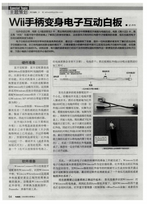
Wii手柄变身电子互动白板
序 ,如 果 前 面 步 骤 正 确 ,此时软件主 界面 会 显示Wi t的 电量 等 i e mo 信 息 ,点击Ca b ain l rt i o 按 钮 进 行 定 位 ,依 次 点击 软件提示 的四 个点 ( 点击是指用红 外 笔 的L D指 向某处 并按 E 下微 动开关 )。至此 红 外笔基本可 以接替 鼠标 了 :按下红外笔开 关就
富 ,那 么推荐使 用S oh o r ( mo tb ad 最
新 版 本 20 , 该 软 件 不 仅 融 合 了 .)
Wi tWhtB ad ono x i e i o r和P itf 程序 mo e i 的 功能 ,而 且还 提供 额 外 的定 位 功 读 取 并 转 化
f ●e ti o
接Wi t的方法略有不 同 ,这里推 i e mo 荐采用Wid ws n o 系统 自带的蓝牙驱动 搭配Wi tC n et 件 ( i e onc mo 软 下文就是 以Wid ws P 的 自带蓝 牙管理 n o S3 XP 器 为例 )。 Wi t控制器 :Wi t控制 i e mo i e mo
( 红外线 LD笔示意图 ) E
首先在废弃的笔身握笔处 开一
个 小 孔 ,给 微 动 开 关 连 上 电线 并 置
入微动开关 。然 后在笔前端为 红外
线L D灯连 上 电线并 固定 ( 意 :红 E 注
器 其实 是一 个 高性 能 的红 外线 感应 器 ,集 成 了高 性能 低功 耗 的蓝 牙连 接技术 ,因此可 以做接收感应器 。
WinterBoard美化系列教程二:自制主题
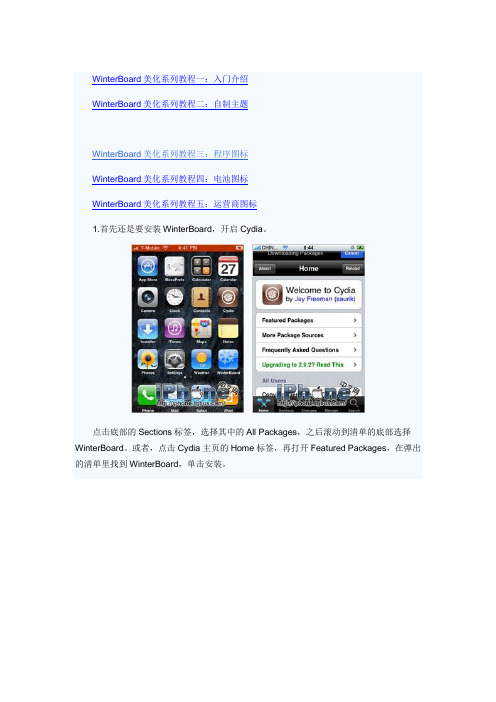
WinterBoard美化系列教程一:入门介绍WinterBoard美化系列教程二:自制主题WinterBoard美化系列教程三:程序图标WinterBoard美化系列教程四:电池图标WinterBoard美化系列教程五:运营商图标1.首先还是要安装WinterBoard,开启Cydia。
点击底部的Sections标签,选择其中的All Packages,之后滚动到清单的底部选择WinterBoard。
或者,点击Cydia主页的Home标签,再打开Featured Packages,在弹出的清单里找到WinterBoard,单击安装。
注意:WinterBoard经常升级,本教程所说的并不见得适用于WinterBoard的最新版本,如果随后更新的WinterBoard里新添加了特性,我们会对应的在教程中有所反应。
点击Install按钮安装,安装结束后,点击Reload SpringBoard按钮。
苹果用户可以用Fugu来向iPhone上传文件,它相当于WinSCP(NoWiFi绿色版,可以USB直连)、T otalCommander、iPhoneTunnelSuite,抑或CuteFTP(点击软件名称直接进入相关教程),使用这些软件之前一定要先安装SSH协议,如果你没有安装OpenSSH,那么你将无法连接iPhone,更不用说传文件啦!如果你已经确定了要给你的小爱换副马甲,那么请先把现在衣服收好(替换文件前做好备份),这样能确保你马甲更换失败后能有衣服穿,否则,你只能带着一个白苹果裸奔啦。
记住:在备份文件之前,不要轻易改写系统文件,否则你有可能会重新刷机!虽然WinterBoard 比之前的软件安全了不是一星半点儿,可是我们还是要小心。
WinterBoard也是有很多问题滴。
下面你可能要对一个最基本主题的参数有一些了解,否则你做出的衣服可能会不太合身。
* StatusBar.png状态栏,用于放置运营商图标、Wi-Fi图标、电池电量显示、时间,大小为320x20像素,并且没有透明设置。
电子魔方的制作方法

电子魔方的制作方法电子魔方是一种刺激智力和手眼协调能力的益智玩具,其拼解难度可根据个人需要进行调整,非常受到广大玩家的喜爱。
在这篇文章中,我将详细介绍一种制作电子魔方的方法,希望能够帮助那些喜欢DIY的朋友们。
首先,我们需要准备以下材料和工具:1. Arduino主控板:Arduino UNO R32. 电子魔方机械结构:我们可以使用3D打印技术制作魔方的机械结构。
在网上搜索“魔方机械结构3D打印模型”,可以找到许多开源的模型文件,可以根据自己的需求进行选择。
3. 伺服电机:我们需要6个伺服电机来控制魔方的六个面。
选择合适的伺服电机需要根据魔方的大小和自己的预算来决定。
4. 杜邦线:用来连接Arduino主控板和伺服电机。
5. 电源:我们可以使用适配器或者电池来为Arduino主控板和伺服电机提供电源。
6. 螺丝和螺母:用来固定伺服电机和魔方机械结构。
接下来,我们可以按照以下步骤进行电子魔方的制作:第一步,将机械结构组装起来。
我们可以根据3D打印模型的说明来组装机械结构,将机械结构的各个零件用螺丝和螺母固定好。
第二步,将伺服电机安装在机械结构上。
首先将伺服电机的输出轴与机械结构的对应部位连接好,然后将伺服电机固定在机械结构上,确保电机的位置正确并且稳固。
第三步,将Arduino主控板与伺服电机连接起来。
我们可以根据 Arduino主控板和伺服电机的引脚定义图,将杜邦线插入到对应的引脚上,然后固定好连接线。
第四步,将Arduino主控板通过USB线连接到电脑上,并且打开Arduino IDE软件。
在软件中,我们可以写程序来控制伺服电机的运动,使之能够模拟魔方的转动。
第五步,测试电子魔方的转动。
在Arduino IDE软件中,我们可以编写一个简单的程序来测试魔方的转动效果。
通过按下不同的按钮或者输入不同的指令,我们可以控制伺服电机的转动方向和角度。
通过不断进行尝试和调整,我们可以使电子魔方的转动效果更加精准和顺畅。
自制上课摸鱼小手工按键

自制上课摸鱼小手工按键
在日常生活中,学生们总会在上课时偷偷摸鱼,这种行为既影响了个人的学习效果,也会干扰到周围同学的学习秩序。
为了解决这一问题,我们可以尝试制作一个小手工按键,帮助学生在上课时集中注意力,提高学习效率。
材料准备
•纸板/硬纸纸
•铝箔纸
•电子元件:导线、按钮开关
制作步骤
1.准备一个小块纸板或硬纸纸作为按键的基座;
2.在基座上贴上一层铝箔纸,作为按键的导电膜;
3.将导线连接到铝箔纸上,并安装按钮开关;
4.将整个按键固定到书桌的一角或自制的支架上。
使用方法
1.将自制的上课摸鱼小手工按键放置在靠近自己的位置;
2.在需要摸鱼时,轻轻按下按键,电路闭合,可以制造出按键声音;
3.当老师或同学发现时,立刻释放按键,避免被发现。
通过制作这个自制小手工按键,学生可以在上课时更加注意听讲,提高学习效率。
同时,这也是一种有趣的手工制作活动,可以锻炼学生的动手能力和创造力。
希望这个自制的上课摸鱼小手工按键能够帮助学生们更好地专注学习,享受学校生活的乐趣!。
如何自制平板触屏笔
如何自制平板触屏笔
自制平板触屏笔折腾起来,绝不是一件简单的事情。
不过,有一些技巧可以使整个过程变得更加容易和有趣。
首先,准备好所有必要的材料,包括一支电动笔、一个普通的双头接插件、几根铜线和一块磁性带。
将接插件一端接到电动笔上,另一端用铜线接触磁性带。
这样,磁性带将可以控制电动笔的移动。
接下来,需要配置覆盖在磁性带表面的可编程芯片,用于编程鼠标的行为。
可编程芯片可以通过计算机编程,以实现鼠标动作的自动化操作。
此外,需要制作一块触摸板,用于捕获磁性带上移动信息。
触摸板需要安装在机箱上,并且将同样的磁性带与笔联系起来,以便更有效地收集移动信息。
最后,将磁性带的数据转换为有用的数据,就可以将自制的平板触屏笔连接到计算机上。
自制平板触屏笔,虽然系统相对复杂,但上述步骤执行下来,就可以让触屏笔达成精准定位,使用起来非常方便。
它也比商业产品更具创新性,特别是能被个性化定制。
不过,自制平板触屏笔需要较高的维护要求,了解安装维护手册,纠正错误操作,维护保养是必须的。
自制电子白板报告
项目2 自制电子白板
1 软硬件环境
软件:Windows操作系统、Smoothboard、Pointofix、WiimoteWhiteboard 硬件: Wii手柄、带有蓝牙功能的电脑、红外线光源笔
2 工作原理
Wii手柄捕捉红外线光源笔发出的信号,处理信号并将其转换成坐标,计算完成的坐标由Wii手柄通过蓝牙发送给电脑,并在电脑的Pointofix呈现出红外线光源笔所画出的图形。
3 实现过程
①红外线光源笔的制作:将一个能发射红外线的二极管用导线与瞬时开关和电池连接(二极管不能接反)。
图1自制红外线光源笔
②打开电脑,将Wii手柄正对电脑屏幕放置,打开Smoothboard软件通过蓝牙搜索并连接Wii手柄,连接成功后进行触点的矫正,最后使用红外线光源笔画一些图形。
图2通过红外线光源笔画出的图形
4 总结
通过Wii 手柄和红外线光源笔,加上配套软件,达到了低投入而可以实现电子白板功能的效果,这项发明在多媒体、游戏等领域有着广泛的应用前景,是一项极具实用价值与创新思维的发明创造。
普罗米修斯电子白板(inspireactiv)神奇墨水制作教程
普罗米修斯电子白板inspireactiv(普米电子白板)神奇墨水制作教程本教程手把手教你如何制作普米电子白板的神奇墨水对象,一看就能上手!确实神奇,它能擦除上层的图片或者文字,当神奇墨水停留的地方可以透过上一层对象看到下一层的对象,往往用于显示不透明图层下面的对象。
例子:我们想制作这样一个页面:页面上有一副图一,将图二覆盖在上面,在页面上放一个“神奇墨水”透过图二看图一上的各种建筑,即图三的效果。
图一图二图三制作步骤:1、放置图片:在页面上放上图一,然后覆盖上图二2、查看图层分布:在浏览器上点击“对象浏览器”图标,切换到对象浏览器,在浏览器里通过双击对象可以给对象更改名字,我们分别给两张图片更改名字为“上层图”,“下层图”。
此时要注意,“神奇墨水”只能透过顶层对象看到中间层对象,所以“上层图”及“下层图”应分别处在“顶层”及“中间层”,如果图片所处层次不对可以在对象浏览器里用鼠标按住对象在层次间移动。
3、调用“神奇墨水”:点击主工具箱的“神奇墨水”小图标,或者通过菜单“工具—神奇墨水”;4、制作:调用“神奇墨水”后在页面上点击一下(或者按住鼠标不动在页面上涂抹形成更大的形状),产生一个“神奇墨水”对象;同时在对象浏览器中多出一个“钢笔”命名对象,自动处于“上层图”的上一层(如果未在上一层需要调整到上层)。
5、调整“神奇墨水”:产生一个“神奇墨水”对象后,点击主工具箱里的“选择”工具释放“神奇墨水”工具,进行“神奇墨水”工具的调整。
6、制作“神奇墨水”外套圈:使用主工具版中的“形状”工具选择圆形形状,在主工具板中“画笔调色区”调整圆形的外边框颜色、“画笔粗细调节区”调整圆形的外边框粗细、“图形内部区域色彩”则选择右下角把圆形的中心区设置成透明。
画笔调色区画笔粗细调节区图形内部区域色彩设置好圆形的各部分的属性后,在页面上拉鼠标画出一个圆圈,点击“选择”工具释放“形状”工具。
此时会出现看不到图形的情况,用对象浏览器查看可以发现上面画的“形状2”处于中间层,我们将它拉到顶层并处在“神奇墨水”对象“钢笔3”上一层。
海尔电子洗衣机产品说明书
Section 6: Parts DataDC50X264310131211216547Cabinet GroupKey Part Number Description Quantity * 9960-285-008Door Assy., Loading Complete-Wht (2)* 9960-285-011Door Assy., Loading Complete-SS (2)* 9960-285-007Door Assy., Loading Complete-Chrome/BLK/SS (2)1 9960-284-002Door Assy., Loading-SS(ring only) (2)1 9960-284-004Door Assy., Loading-Chrome(ring only) (2)2 9982-353-002Plate Assy., Hinge (Wht) No Pin (2)2 9982-353-001Plate Assy., Hinge (SS) No Pin (2)* 9545-012-015Screw, Hinge to Door (8)* 8640-413-002Nut, Hinge to Door (8)3 9212-002-004Glass, Door (2)4 9206-413-002Gasket, Glass Black (2)* 9548-117-000Support, Door Glass (2)5 9206-420-005Gasket, Outer Rim Black (2)6 9244-082-001Handle, Loading Door (2)* 9545-018-017Screw, Handle 1/4-20 x 3/8 (4)* 9531-033-003Stud, Door Catch (2)* 8640-413-001Nut, Hex (2)* 8640-413-003Nut, Acorn (2)* 9086-015-002Catch, Loading Door (2)* 8638-190-009Pop Rivet for mtg. catch (4)* 8641-582-006Lockwasher (4)* 8640-399-001Spring Nut (6)7 9989-521-003Panel Assy., Front- Lower (Wht) (1)7 9989-521-001Panel Assy., Front- Lower (SS) (1)8 9989-517-003Panel Assy., Front- Upper (Wht) (1)8 9989-517-001Panel Assy., Front- Upper (SS) (1)* 9277-054-001Insulation Front Panel, half moon (top) (2)* 9277-054-002Insulation Front Panel, half moon (bottom) (2)9 9545-008-014Screw, FLHDCR, 10B x 1 (14) (6)* 8641-585-001 Lockwasher* 8640-399-001Nut, Spring (12)10 9544-069-002Strap, Hinge (Wht) (2)10 9544-069-005Strap, Hinge (SS/Black) (2)* 9545-012-028Screw, Hinge to Panel (8)11 9545-052-001Screw, Door to Hinge Strap (Special Black Type) (2)12 8641-436-003Washer, Fiber (2)13 9021-041-001Acceptor, Coin (1)* 9486-149-001Retainer, Coin Acceptor (2)14 9545-053-002Screw (4)* 9801-099-001Switch, Optical (1)Cabinet Group ContinuedKey Part Number Description Quantity15 9994-032-001Escutcheon, Upper (1)16 9435-039-002Trim, Overlay-Upper Blue (1)16 9435-039-001 Trim, Overlay-Upper Black (1)17 9994-033-001Escutcheon, Lower (1)18 9435-023-001Trim, Overlay-Lower Blue (1)18 9435-031-001Trim, Overlay-Lower Black (1)* 9545-020-009Screw (20)19 9412-167-002Nameplate Stack Dryer Express Blue (1)19 9412-167-001Nameplate Stack Dryer Express Black (1)20 9866-005-001Lint Drawer Assembly Blue (2)20 9866-005-004Lint Drawer Assembly Black (2)21 9435-024-001Overlay Trim, Lint Drwr-Blue (1)21 9435-032-001Overlay Trim, Lint Drwr-Black (1)* 9532-074-003Felt Seal ( back of lint screen assembly ) (2)* 9805-033-002Lint Screen Assembly ONLY (no front) (2)* 9555-057-008Replaceable Lint Screen Only (2)22 8650-012-004Lock and Key, Lint Drawer (2)* 6292-006-010Key 6101 only (2)* 9095-043-001Cam, Lock (2)* 9545-008-001Lint Screen Strap Hold Down Screws 10Bx 1/4 (32)23 9857-198-001Controls Assy, Blue (1)23 9857-198-003Controls Assy, Black (1)* 9627-869-001Harness, Electronic Control (1)24 8650-012-003Lock and Key, Control (1)* 9095-041-001Cam, Lock (1)* 6292-006-007Key only 6324 (1)* 9627-855-003Harness, Heat Sensor (1)* 8640-276-002Wire Nut Connector Grey (4)25 9501-004-003Sensor Temp Control (2)26 9501-008-001Bracket for Heat Sensor Mounting (Under Basket) w/ sensor..2* 9545-045-005Screw, Round Head (Mounts sensor; phillips head) (2)* 9209-037-002Gromm.et, 3/16 ID (2)* 8544-006-001Leg, Leveling 1/2” (4)* 9074-320-001 Cover, Cabinet (Top) (1)* 9277-041-017 Insulation Cabinet Cover (1)* 9732-276-001Kit for Dryers without Neutral and using 208-240 volt (1)* 9732-102-013LP Kit for 50Lb Stk Dryers (1)* 9732-243-001Stack Dryer Trunion Puller (1)* 9544-041-002 Strap - Bead Tie (1)27 9942-038-005 Vault, Coin Box (1)* 9545-008-024 Screws, Mounting-Coin Vault (2)28 9897-099-002 Coin Box Assy, Large Blue (1)28 9807-099-004 Coin Box Assy, Large Black (1)191526252792531089Control Parts GroupKey Part Number Description Quantity * 9857-198-001Controls Assy, Electronic Mounted With Membrane Switch, BLU (1)* 9857-198-003Controls Assy, Electronic Mounted With Membrane Switch, BLK (1)1 9826-008-001 Trough Assembly (1)2 9032-062-002 Button-Push, Control, Blue (2)2 9032-062-001 Button-Push, Control, Black (2)3 9538-166-011Spacer-Metal, 4mm (4)4 9486-158-001 Retainer-Push Button (2)5 8640-424-002Nut-Hex, Elastic stop, #4-40 (4)6 8652-130-038Terminal-Grounding clip (1)7 9534-365-001Spring-Flat, Control (1)8 9545-008-001Screw-Hex, #10B x 1/4 (2)9 9545-044-010 Screw-Hex, #10B x 1/4 (10)9 8641-582-005Washer-External tooth, #6 (10)10 9435-038-001Overlay-Control, Coin, Black (1)10 9435-038-002Overlay-Control, Coin, Blue (1)11 9021-041-001Acceptor-Coin, Optical (1)* 9486-149-001Retainer, Coin Acceptor (1)12 9545-053-002Screw (4)* 9801-099-001 Optical Sensor, Replacement (1)Note: Jumpers required if using 1.5 Control on Older Machines (P9 Connection)* 8220-155-001 Wire Assy, Jumper, 30Lb Stack Coin (1)* 8220-155-002 Wire Assy, Jumper, 50Lb Stack Coin (1)Door Switch GroupPart NumberDescription Quantity9539-487-001Door Switches (2)Hinge Plate Cover1 9074-340-002 Cover-Hinge, Black .....................................................................22 8636-008-010 Screw-TRHDCR, 10B x 3/8, Black.. (4)12Bearing Housing GroupKey Part Number Description Quantity J1 9241-189-002 Housing, Bearing (2)J2 9036-159-003Bearing, Ball Rear..................................................................... .2 * 9538-183-001 Spacer, Bearing (2)* 9036-159-001Bearing, Ball Front .................................................................... .2 J5 9545-017-017Bolt, 1/2 x 3/4 . (8)J7 8640-417-002Nut, 1/2 (8)* 9803-201-001Bearing Housing Complete Ass’y (includes bearings,spacer) (2)J4 9545-017-018Screw 1/2 x 1 1/2 (4)Burner Housing GroupKey Part Number Description Quantity * 9803-207-001 Housing Assembly, Burner (2)1a 9452-730-001Service Burner Plate Front... (2)1 9452-729-001 Service Plate baffl e Recirculation Chamber Clean Out (2)* 9545-008-006Screws (8)2 9545-008-001Screw (16)18 9003-220-001Angle, Burner Support (2)* 9545-008-006Screw (4)17 9048-020-002Burner, Main (4)* 9545-008-006Screw 10AB x 3/8” (4)* 9454-824-001 Panel, Back Burner Housing (2)4 9545-008-001Screw 10B x1/4” (8)5 9875-002-003Electrode Assy, Ignition (2)19 9545-045-001Screw, Electrode Mtg 8B x 1/4” (4)7 9379-186-001Valve, Gas Shut Off (1)8 9857-134-001Control Assy, Gas (2)9 9381-012-001Manifold, Assy (2)* 9425-069-021Orifi ce, Burner-Natural #27 (4)* 9425-069-022Orifi ce, Burner-LP #44 (4)10 9029-175-001Bracket, Manifold (2)22 8615-104-038Pipe Plug in end of Burner Manifold (2)* 9545-008-006Screw (4)12 9576-203-002Thermostat, Hi-Limit (2)* 9538-142-001Spacer, Hi-Limit (4)* 9545-045-007 Screw 8B x 3/4” (4)13 9074-329-001Cover, Hi-Limit Stat Ignitor (2)* 9545-008-006Screw (6)* 9576-207-008Thermostat, Safety Shutoff (2)* 9545-008-006Screw (4)15 9825-062-001Cover, Safety Stat (2)* 9545-008-024Screw (6)16 9857-116-003Control, Ignition Fenwall (3 trybox) (2)* 9732-102-013Kit, LP Conversion 50Lb Stack Kit (2)* 9838-018-003Welded One Piece Gas Pipe Assembly (1)Part # 8533-085-001 9/14Burner Housing Group Photos10221092221851A141594851613Rear ViewKey Part Number Description Quantity * 9627-861-001Wire Harness Overtemperature Switch/Air Switch (2)* 9801-098-001Switch Assy, Air Flow (2)1 9539-461-009Switch, Air Flow (2)2 9029-200-001 Bracket, Switch- Air Flow (2)3 9008-007-001Actuator, Switch (2)4 9451-169-002Pin, Cotter (2)5 9545-020-001Screw 4-40 x 5/8” (4)* 8640-401-001Nut, Special Twin .#4-40 (2)* 9550-169-003Shield, Switch (2)6 9376-322-001Motor, Drive (2)7 9452-770-001Plate, Motor Mounting (1)* 9545-029-008Bolt 3/8” - 16 x 3/4” (8)* 8641-582-003Lockwash Spring 3/8 (8)8 9545-018-019Screw, Motor Plate to Back Assy. 1/4-20x 2 1/2 (8)* 8641-582-007Lockwasher 1/4 (8)9 9538-163-006Spacr (8)* 8641-581-017Flat Washer 1/4 x 7/8 (24)* 9209-086-002Rubber Grommet (8)* 9538-166-006Grommet Spacers (8)* 9545-028-013Screw, Set (4)10 9962-018-002Back Assy, Blower Hsg (2)11 9991-053-001Support Assy, Intermed. Pulley (2)12 9545-029-010Bolt, Rd Hd 3/8-16 x 1 1/4 (6)12 8640-415-004Nut Flange Wizlock 3/8” - 16 (6)12 8641-581-035Washer, Flat (6)13 9545-029-003Bolt, 3/8-16 x 1 1/2 (2)14 9861-022-001Arm Assy-Tension, Complete (2)* 9487-200-003Ring-Retaining (6)15 9908-048-003Pulley Assy, Intermediate with bronze fl ange bearing (2)* 9036-145-002Bronze Flange Bearing (4)16 9908-047-002Pulley Driven Tumbler (2)17 9040-076-009Belt, Drive Motor (2)18 9040-073-011Belt, Driven Intermediate to Tumbler (2)19 9534-151-000Spring, Tension (2)20 9099-012-005Chain, Tension (2)21 9248-022-002Hook, Tension (2)* 9451-146-001Pin, Damper Hinge (2)* 9074-334-001 Cover Duct Upper (1)22 9973-032-001 Heat Recirculation Assembly Duct (2)* 9453-169-013Motor Pulley - Driver (1)* 9545-028-013Set Screws (2) (2)* 9278-043-001Impeller23 8641-581-026Washer, Flat 1/2” for Tumbler Pulley (2)24 9545-017-009Bolt, 1/2”-13 x 1 1/4 (2)25 8641-582-016Washer, Star 1/2” for Tumbler Pulley (2)* 9545-008-001Screw 10 Bx 1/4” (6)* 9545-014-004Bolt, 5/16-18 x 5/8” (8) (8)5/16-18* 8640-400-003Nut,* 9538-184-001Spacer, Shaft (2)* 9487-234-005Ring Tolerance (2)* 9125-007-001Damper Inside Duct Exhaust (2)* 9125-007-002Damper Inside Duct Exhaust (1)* 8520-141-000Nut, Spring (4)* 9074-335-001Cover Duct Lower (1)* 9545-008-024Screw 10ABx 3/8” (72)* 9029-173-001Bracket for Wire Harness Under Burner Housing (2)Part # 8533-085-001 9/14Part # 8533-085-001 9/14Rear View Photos1264722Rear Panel & Cover GroupKey Part Number Description Quantity19208-090-001Rear Guard Side Panel 1 (2)4 9545-008-024Screws 10 AB x 3/8 (30)5 8502-649-001Label - Connection Electrical (1)8 9208-089-001Rear Guard Back Panel (2)10 8502-600-001Label Warning & Notice (1)11 8502-645-001Label - Instructions (1)12 9109-113-001Transition Assembly Outlet (1)13 9074-320-001 Top Cover Dryer Panel (1)14 9550-188-001 Top Burner Housing Heat Shield Inlet (1)15 9074-321-001 Top Panel Burner Housing Cover (1)Part # 8533-085-001 9/141851113121514Tumbler GroupKey Part Number Description Quantity 9848-131-001Tumbler Assembly Galvanized w/spider (2)G2 9568-013-001Spider Assembly (2)G3 9497-226-002Rod, Tumbler (6)G4 8640-417-005Nut, 1/2 - 13 (6)G6 8641-590-002Washer, Special (6).............................................................................AR G7 9552-013-000Shim* 9848-130-002Tumbler Assembly Stainless Steel (2)G1 9848-130-001Tumber Assembly Galvanized (2)Part # 8533-085-001 9/14Control Assembly GroupKey Part Number DescriptionQuantity* 9857-189-001 Control Assmbly Complete (all below included) .............................1* 9108-117-001 Control Box Cover ..................................................................... 1* 8220-001-478 Wire Assembly Green 7” ............................................................ 1* 8639-621-007 Screw #10-32 x 12 Green ............................................................1* 8641-582-006 Lockwasher Ext Tooth #10 ..........................................................13 9897-026-002 Terminal Block Main Power Middle ...............................................14 9897-026-001 Terminal Block ............................................................................2* 9545-045-012 Screw #8 ABx 1/2 for terminal block ............................................6 5 8711-011-001 Transformer Ignition ...................................................................2* 9545-008-024 Screws 10AB x 3/8” ...................................................................46 9982-348-001 Plate Assembly MTG Ignition Control............................................2* 9545-008-024 Screws 10B x 1/4” MTG Above Plate and Others ...........................47 9857-116-003 Ignition Control ..........................................................................2* 8640-411-003 #6-32 Nuts ................................................................................48 9631-403-009 Wire Assembly High Voltage Upper ..............................................19 9627-860-001 Wire Harness Ignition Control Upper ............................................110 9627-860-002 Wire Harness Ignition Control Lower ............................................1* 9053-067-002 Bushing Wire 7/8” .......................................................................413 9200-001-002 Fuseholder Assembly ..................................................................314 8636-018-001 Fuse 1.5 Amp .............................................................................315 5192-299-001 Relay Power ...............................................................................216 9897-035-001 Terminal Block Assembly Main Power Inlet ...................................1* 9545-008-024 Screw #8 AB x 1/2” ....................................................................2* 8220-062-036 Wire Assembly Red/Black 14” ......................................................1* 8220-062-037 Wire Assembly Red/White 14” .....................................................1* 8220-062-038 Wire Assembly White 14” ............................................................221 9627-864-004 Wire Harness Motor Extension .....................................................2* 9527-007-001 Stand Off - Wire Saddle / Arrowhead ..........................................13* 9545-031-005 Screw 6 B x 3/8” ........................................................................422 9558-029-003 Strip Terminal Marker (Behind Input Power) ..................................124 9627-863-001 Wire Harness Main Extension Access Under Burner Housing .........123 9631-403-008 Wire Ass’y - High Voltage Lower ..................................................125 9627-859-001 Wire Harness - Main Power (1)Part # 8533-085-001 9/14Control Assembly GroupPart # 8533-085-001 9/1416252223245Coin AccecptorKey Part Number Description Quantity1 9021-041-001Coin Accecptor, Optical (1)Replacement (1)2 9801-099-001Sensor-Optical,3 9545-039-002Screw, Heighth Bar, 3mm (2)* 9486-136-001 Retainer, Coin Acceptor (1)* 9545-053-002 Screw (4)Part # 8533-085-001 9/14NotesPart # 8533-085-001 9/14NotesPart # 8533-085-001 9/14Section 7: VoltageConversionPart # 8533-085-001 9/14Part # 8533-085-001 9/14Instructions - Convert a Dual Voltage Stack Dryer from 120V to 208-240V with Neutral Wire Only1. Remove incoming power from the dryer. Use a known working voltmeter to check power.2. Remove the cover of both the upper and lower control box assemblies from the dryer using a 5/16” wrench.3. Move the black/blue wire from the N position of the main power terminal block to the L2 position of the mainpower terminal block in the upper control box assembly. See Figure 6 below.4. Move the white wire of the upper motor harness to an upper inner left terminal in the middle terminal block in thelower control box assembly. See Figure 6 below.5. Move the orange wire of the upper motor harness to an upper inner left terminal in the middle terminal block inthe lower control box assembly. See Figure 6 below.6. Move the white wire of the lower motor harness to a lower inner left terminal in the middle terminal block in thelower control box assembly. See Figure 6 below.7. Move the orange wire of the lower motor harness to a lower inner left terminal in the middle terminal block in thelower control box assembly. See Figure 6 below.8. Reconnect power to the dryer and test to ensure proper operation; one line voltage to L1, one line voltage to L2,the neutral to N, and the earth ground to E.9. Reinstall the cover of both the upper and lower control box assemblies from the dryer using a 5/16” wrench.Part # 8533-085-001 9/14NotesPart # 8533-085-001 9/14Section 9: MaintenancePart # 8533-085-001 9/14MaintenanceDaily1. Clean lint screen by unlocking and sliding out in their tracks for access. Use soft brush ifnecessary. Failure to do so will slow drying and increase gas usage and temperatures through out the dryer.2. Check lint screen for tears. Replace if necessary.Monthly1. Remove lint accumulation from end bells of motor.2. Clean lint from lint screen compartment.3. Remove lint and dirt accumulation from top of the dryer and all areas above, and around theburners and burner housing. Failure to keep this portion of the dryer clean can lead to a buildup of lint creating a fi re hazard.4. Inspect Recirculation burner housing for excessive buildup.5. Place a few drops of light oil on top and bottom pivots of the clothes door hinge.6. Grease bearings and shaft of intermediate drive pulley.Quarterly1. Check belts for looseness, wear or fraying.2. Inspect gasket of door glass for excessive wear.3. Check tightness of all fasteners holding parts to support channel.4. Check tightness of tumbler shaft retaining nut. MUST MAINTAIN 150 FOOT LBS.5. Remove lint accumulation from primary air ports in burners.6. Grease pivot pins and tension arms where in contact with each other.Semiannually1. Remove and clean main burners.2. Remove all orifi ces and examine for dirt and hole obstruction.3. Remove all lint accumulation. Remove front panel, lint screen housing and remove lintaccumulation.Annually1. Check intermediate pulley bearings for wear.2. Check and remove any lint accumulation from exhaust system.NOTE: DRYER MUST NOT BE OPERATED WITHOUT LINT SCREEN IN PLACE。
- 1、下载文档前请自行甄别文档内容的完整性,平台不提供额外的编辑、内容补充、找答案等附加服务。
- 2、"仅部分预览"的文档,不可在线预览部分如存在完整性等问题,可反馈申请退款(可完整预览的文档不适用该条件!)。
- 3、如文档侵犯您的权益,请联系客服反馈,我们会尽快为您处理(人工客服工作时间:9:00-18:30)。
DIY In
Required Hardware Hardware
Wii remote controller ($34.99)
/Nintendo-Remote-Wiimote-Jacket-Xbox-
360/dp/B0010ZPZAO/ref=pd_sim_e_2 Microphone holder($1.47)
/Musicians-Gear-Clip-Type-Microphone-
Holder/dp/B0002E3MS6/ref=pd_sim_MI_ 7
Microphone stand($12.99)
/Musicians-Gear-Die-Cast-Stand-
Black/dp/B0018TAITA/ref=pd_cp_MI_3 Projector
PC computer
Now let’s put them all together and see how they work.
Set up steps
1. Setup your projector properly and connect your projector to your PC computer; we recommend you fix your projector’s position, in that case you don’t have to do the calibration next time;
2. Setup your Wiimote controller and make the infrared camera size(black rectangle) points to the projective area;
We recommend the distance and position as the following:
(45degree to the projective area)
3. Plug your Bluetooth adapter into your PC
Most of the Bluetooth adapters don’t require a driver. (check the compatibility list for the wiimote :
/wiki/List_of_Working_Bluetooth_Devices ) Now you’ve done all the hardware’s setup!
For ceiling mounted Wiimote, we strongly recommend you to read this useful article by shaggymook .
/id/Ceiling-Mounted-Wiimote-Whiteboard/
There is a solution for how to replace wiimote’s battery with a 3v transformer! The way he handles Button 1 and 2 will save you a lot of time on wiimote connection configuration.
Software configuration
Required software list:
iWiiBoard (Current version: 4.0) $29.99
Interactive whiteboard software
Publisher:
Use iWiiBoard’s built-in automated Wiimote connect to search and connect your wii remote
1. Click Wiimote search button to launch Wiimote search program to search and add Bluetooth service for your Wiimote; The search program will be launched in 9 seconds automatically;
The search program will automatically search and add your Wiimote; Please make sure you have your Bluetooth adapter plugged into your PC’s usb slot before run the program; after the search is completed, iWiiboard will launch Calibration program automatically;
Important:
•Make sure your computer is bluetooth enabled and your bluetooth hardware is working properly; (check
the compatibility list)
•As iWiiboard uses Microsoft bluetooth stack,you have to remove other bluetooth softwares such as
BlueSoleil,Widcomm,Dell/HP/ect Laptop Inbuilt
Stack,Toshiba,Logitech Stack from Control Panel to
avoid conflicts;
•Please make sure you use iWiiboard searching your wii remote in your wii remote's DISCOVERY
mode.(You have to press 1 and 2 button)
2. Whiteboard calibration
ANY visible IR source will trigger mouse events and manipulate your computer.
Any unintentional IR sources may result in undesired behavior. BE CAREFUL where you point the wiimote.
Click the button "Calibrate Location" or press the A button on the wiimote to begin touch calibration.
Use your IR light pen to touch each crosshair and activate the LED (as if pressing your mouse button to click).
After 4 points are calibrated, the touch screen should be ready to use.
Recalibration (and auto-loading last calibration)
To recalibrate, simply press the calibration button again (note the mouse control may not work yet if the calibration was poor) or press your wiimote A button. When the program is launched, it will reload the last calibration. If your wiimote and display configuration has not changed, re-calibration may not be necessary.
Controls
1. Pressing the A button on the wiimote will activate the calibration once the whiteboard application is running. If the calibration is already running, this will restart the calibration with the 1st point.
2. Pressing the esc will exit the calibration screen.
3. "Cursor Control" will enable or disable mouse control of the stylus
4. "Smoothing" will average the cursor movement over several samples creating smoother lines, but in exchange for slower tracking.
Please check iWiiBoard User’s Guide for iWiiBoard’s detail usual manual.。