AD 2000-MERKBLATT G2.02
Orgalime S2000
GENERAL CONDITIONSfor theSUPPLY OF MECHANICAL, ELECTRICAL AND ELECTRONIC PRODUCTSBrussels, August 2000PREAMBLE1. These General Conditions shall apply when the parties agree in writing or otherwise thereto. When the General Conditions apply to a specific contract, modifications of or deviations from them must be agreed in writing.The object(s) to be supplied under these General Conditions is (are) hereinafter referred to as the Product.Wherever these General Conditions use the term in writing, this shall mean by document signed by the parties, or by letter, fax, electronic mail and by such other means as are agreed by the parties.PRODUCT INFORMATION2.All information and data contained in general product documentation and price lists, whether in electronic or any other form, are binding only to the extent that they are by reference expressly included in the contract.DRAWINGS AND DESCRIPTIONS3.All drawings and technical documents relating to the Product or its manufacture submitted by one party to the other, prior or subsequent to the formation of the contract, shall remain the property of the submitting party.Drawings, technical documents or other technical information received by one party shall not, without the consent of the other party, be used for any other purpose than that for which they were provided. They may not, without the consent of the submitting party, otherwise be used or copied, reproduced, transmitted or communicated to a third party.4.The Supplier shall, not later than at the date of delivery, provide free of charge information and drawings which are necessary to permit the Purchaser to erect, commission, operate and maintain the Product. Such information and drawings shall be supplied in the number of copies agreed upon or at least one copy of each. The Supplier shall not be obliged to provide manufacturing drawings for the Product or for spare parts. ACCEPTANCE TESTS5. Acceptance tests provided for in the contract shall, unless otherwise agreed, be carried out at the place of manufacture during normal working hours.If the contract does not specify the technical requirements, in the appropriate branch of industry concerned in the country of manufacture.6.The Supplier shall notify the Purchaser in writing of the acceptance tests in sufficient time to permit the Purchaser to be represented at the tests. If the Purchaser is not represented, the test report shall be sent to the Purchaser and shall be accepted as accurate.7.If the acceptance tests show the Product not to be in accordance with the contract, the Supplier shall without delay remedy any deficiencies in order to ensure that the Product complies with the contract. New tests shall then be carried out at the Purchaser's request, unless the deficiency was insignificant. 8.The Supplier shall bear all costs for acceptance tests carried out at the place of manufacture. The Purchaser shall however bear all travelling and living expenses for his representatives in connection with such tests.DELIVERY. PASSING OF RISK9.Any agreed trade term shall be construed in accordance with the INCOTERMS in force at the formation of the contract.If no trade term is specifically agreed, the delivery shall be Ex works (EXW).If, in the case of delivery Ex works, the Supplier, at the request of the Purchaser, undertakes to send the Product to its destination, the risk will pass not later than when the Product is handed over to the first carrier.Partial shipments shall be permitted unless otherwise agreed.TIME FOR DELIVERY. DELAY10.If the parties, instead of specifying the date for delivery, have specified a period of time on the expiry of which delivery shall take place, such period shall start to run as soon as the contract is entered into, all official formalities have been completed, payments due at the formation of the contract have been made, any agreed securities have been given and any other preconditions have been fulfilled.11.If the Supplier anticipates that he will not be able to deliver the Product at the time for delivery, he shall forthwith notify the Purchaser thereof in writing, stating the reason, and, if possible,ORGALIME S 2000If the Supplier fails to give such notice, the Purchaser shall be entitled to compensation for any additional costs which he incurs and which he could have avoided had he received such notice.12.If delay in delivery is caused by any of the circumstances mentioned in Clause 39 or by an act or omission on the part of the Purchaser, including suspension under Clauses 20 or 42, the time for delivery shall be extended by a period which is reasonable having regard to all the circumstances in the case. This provision applies regardless of whether the reason for the delay occurs before or after the agreed time for delivery.13.If the Product is not delivered at the time for delivery (as defined in Clauses 10 and 12), the Purchaser is entitled to liquidated damages from the date on which delivery should have taken place.The liquidated damages shall be payable at a rate of 0.5 per cent of the purchase price for each completed week of delay. The liquidated damages shall not exceed 7.5 per cent of the purchase price.If only part of the Product is delayed, the liquidated damages shall be calculated on that part of the purchase price which is attributable to such part of the Product as cannot in consequence of the delay be used as intended by the parties.The liquidated damages become due at the Purchaser's demand in writing but not before delivery has been completed or the contract is terminated under Clause 14.The Purchaser shall forfeit his right to liquidated damages if he has not lodged a claim in writing for such damages within six months after the time when delivery should have taken place.14.If the delay in delivery is such that the Purchaser is entitled to maximum liquidated damages under Clause 13 and if the Product is still not delivered, the Purchaser may in writing demand delivery within a final reasonable period which shall not be less than one week.If the Supplier does not deliver within such final period and this is not due to any circumstance for which the Purchaser is responsible, then the Purchaser may by notice in writing to the Supplier terminate the contract in respect of such part of the Product as cannot in consequence of the Supplier's failure to deliver be used as intended by the parties.If the Purchaser terminates the contract he shall be entitled to compensation for the loss he has suffered as a result of the Supplier's delay. The total compensation, including the liquidated damages which are payable under Clause 13, shall not exceed 15 per cent of that part of the purchase price which is attributable to the part of the Product in respect of which the contract is terminated.The Purchaser shall also have the right to terminate the contract by notice in writing to the Supplier, if it is clear from the circumstances that there will occur a delay in delivery which, under Clause 13 would entitle the Purchaser to maximum liquidated damages.In case of termination on this ground, the Purchaser shall be entitled to maximum liquidated damages and compensation under the third paragraph of this Clause 14. 15.Liquidated damages under Clause 13 and termination of the contract with limited compensation under Clause 14 are the only remedies available to the Purchaser in case of delay on the part of the Supplier. All other claims against the Supplier based on such delay shall be excluded, except where the Supplier has been guilty of gross negligence.In these General Conditions gross negligence shall mean an act or omission implying either a failure to pay due regard to serious consequences, which a conscientious supplier would normally foresee as likely to ensue, or a deliberate disregard of the consequences of such act or omission.16.If the Purchaser anticipates that he will be unable to accept delivery of the Product at the delivery time, he shall forthwith notify the Supplier in writing thereof, stating the reason and, if possible, the time when he will be able to accept delivery.If the Purchaser fails to accept delivery at the delivery time, he shall nevertheless pay any part of the purchase price which becomes due on delivery, as if delivery had taken place. The Supplier shall arrange for storage of the Product at the risk and expense of the Purchaser. The Supplier shall also, if the Purchaser so requires, insure the Product at the Purchaser's expense.17.Unless the Purchaser's failure to accept delivery is due to any such circumstance as mentioned in Clause 39, the Supplier may by notice in writing require the Purchaser to accept delivery within a final reasonable period.If, for any reason for which the Supplier is not responsible, the Purchaser fails to accept delivery within such period, the Supplier may by notice in writing terminate the contract in whole or in part. The Supplier shall then be entitled to compensation for the loss he has suffered by reason of the Purchaser's default. The compensation shall not exceed that part of the purchase price which is attributable to that part of the Product in respect of which the contract is terminated.PAYMENT18.Unless otherwise agreed, the purchase price shall be paid with one third at the formation of the contract and one third when the Supplier notifies the Purchaser that the Product, or the essential part of it, is ready for delivery. Final payment shall be made when the Product is delivered.Payments shall be made within 30 days of the date of the invoice.19.Whatever the means of payment used, payment shall not be deemed to have been effected before the Supplier's account has been fully and irrevocably credited.20.If the Purchaser fails to pay by the stipulated date, the Supplier shall be entitled to interest from the day on which payment was due. The rate of interest shall be as agreed between the parties. If the parties fail to agree on the rate of interest, it shall be 8 percentage points above the rate of the main refinancing facility of the European Central Bank in force on the due date of payment.In case of late payment the Supplier may, after having notified the Purchaser in writing, suspend his performance of the contract until he receives payment.If the Purchaser has not paid the amount due within three months the Supplier shall be entitled to terminate the contract by notice in writing to the Purchaser and to claim compensation for the loss he has incurred. The compensation shall not exceed the agreed purchase price.RETENTION OF TITLE21.The Product shall remain the property of the Supplier until paid for in full to the extent that such retention of title is valid under the applicable law.The Purchaser shall at the request of the Supplier assist him in taking any measures necessary to protect the Supplier's title to the Product in the country concerned.The retention of title shall not affect the passing of risk under Clause 9.LIABILITY FOR DEFECTS22.Pursuant to the provisions of Clauses 23-37 inclusive, the Supplier shall remedy any defect or nonconformity (hereinafter termed defect(s)) resulting from faulty design, materials or workmanship.23.The Supplier's liability is limited to defects which appear within a period of one year from delivery. If the daily use of the Product exceeds that which is agreed, this period shall be reduced proportionately.24.When a defect in a part of the Product has been remedied, the Supplier shall be liable for defects in the repaired or replaced part under the same terms and conditions as those applicable to the original Product for a period of one year. For the remaining parts of the Product the period mentioned in Clause 23 shall be extended only by a period equal to the period during which the Product has been out of operation as a result of the defect.25.The Purchaser shall without undue delay notify the Supplier in writing of any defect which appears. Such notice shall under no circumstance be given later than two weeks after the expiry of the period given in Clause 23.The notice shall contain a description of the defect.If the Purchaser fails to notify the Supplier in writing of a defect within the time limits set forth in the first paragraph of this Clause, he loses his right to have the defect remedied.Where the defect is such that it may cause damage, the Purchaser shall immediately inform the Supplier in writing. The Purchaser shall bear the risk of damage resulting from his failure so to notify.26.On receipt of the notice under Clause 25 the Supplier shall remedy the defect without undue delay and at his own cost as stipulated in Clauses 22-37 inclusive.Repair shall be carried out at the place where the Product is located unless the Supplier deems it appropriate that the defective part or the Product is returned to him for repair or replacement.The Supplier is obliged to carry out dismantling and re-installation of the part if this requires special knowledge. If such special knowledge is not required, the Supplier has fulfilled his obligations in respect of the defect when he delivers to the Purchaser a duly repaired or replaced part.27.If the Purchaser has given such notice as mentioned in Clause 25 and no defect is found for which the Supplier is liable, the Supplier shall be entitled to compensation for the costs he has incurred as a result of the notice.28.The Purchaser shall at his own expense arrange for any dismantling and reassembly of equipment other than the Product, to the extent that this is necessary to remedy the defect.29.Unless otherwise agreed, necessary transport of the Product and/or parts thereof to and from the Supplier in connection with the remedying of defects for which the Supplier is liable shall be at the risk and expense of the Supplier. The Purchaser shall follow the Supplier's instructions regarding such transport.30.Unless otherwise agreed, the Purchaser shall bear any additional costs which the Supplier incurs for repair, dismantling, installation and transport as a result of the Product being located in a place other than the destination stated in the contract or - if no destination is stated - the place of delivery.31.Defective parts which have been replaced shall be made available to the Supplier and shall be his property.32.If, within a reasonable time, the Supplier does not fulfil his obligations under Clause 26, the Purchaser may by notice in writing fix a final time for completion of the Supplier's obligations.If the Supplier fails to fulfil his obligations within such final time, the Purchaser may himself undertake or employ a third party to undertake necessary remedial works at the risk and expense of the Supplier.Where successful remedial works have been undertaken by the Purchaser or a third party, reimbursement by the Supplier of reasonable costs incurred by the Purchaser shall be in full settlement of the Supplier's liabilities for the said defect.33.Where the defect has not been successfully remedied, as stipulated under Clause 32,a) the Purchaser is entitled to a reduction of the purchase price in proportion to the reduced value of the Product, provided that under no circumstance shall such reduction exceed 15 per cent of the purchase price, orb) where the defect is so substantial as to significantly deprive the Purchaser of the benefit of the contract, the Purchaser may terminate the contract by notice in writing to the Supplier. The Purchaser is then entitled to compensation for the loss he has suffered up to a maximum of 15 per cent of the purchase price. 34.The Supplier is not liable for defects arising out of materials provided, or a design stipulated or specified by the Purchaser.35.The Supplier is liable only for defects which appear under the conditions of operation provided for in the contract and under proper use of the Product.The Supplier's liability does not cover defects which are caused by faulty maintenance, incorrect erection or faulty repair by the Purchaser, or by alterations carried out without the Supplier's consent in writing.Finally the Supplier's liability does not cover normal wear and tear or deterioration.36.Notwithstanding the provisions of Clauses 22-35 the Supplier shall not be liable for defects in any part of the Product for more than two years from the beginning of the period given in Clause 23.37.Save as stipulated in Clauses 22-36, the Supplier shall not be liable for defects. This applies to any loss the defect may cause including loss of production, loss of profit and other indirect loss. This limitation of the Supplier's liability shall not apply if he has been guilty of gross negligence as defined in Clause 15. ALLOCATION OF LIABILITY FOR DAMAGE CAUSED BY THE PRODUCT38. The Supplier shall not be liable for any damage to property caused by the Product after it has been delivered and whilst it is in the possession of the Purchaser. Nor shall the Supplier be liable for any damage to products manufactured by the Purchaser, or to products of which the Purchaser's products form a part.If the Supplier incurs liability towards any third party for such damage to property as described in the preceding paragraph, the Purchaser shall indemnify, defend and hold the Supplier harmless.If a claim for damage as described in this Clause is lodged by a third party against one of the parties, the latter party shall forthwith inform the other party thereof in writing.The Supplier and the Purchaser shall be mutually obliged to let themselves be summoned to the court or arbitral tribunal examining claims for damages lodged against one of them on the basis of damage allegedly caused by the Product.The limitation of the Supplier's liability in the first paragraph of this Clause shall not apply where the Supplier has been guilty of gross negligence as defined in Clause 15. FORCE MAJEURE39.Either party shall be entitled to suspend performance of his obligations under the contract to the extent that such performance is impeded or made unreasonably onerous by any of the following circumstances: industrial disputes and any other circumstance beyond the control of the parties such as fire, war, extensive military mobilization, insurrection, requisition, seizure, embargo, restrictions in the use of power and defects or delays in deliveries by sub-contractors caused by any such circumstance referred to in this Clause.A circumstance referred to in this Clause whether occurring prior to or after the formation of the contract shall give a right to suspension only if its effect on the performance of the contract could not be foreseen at the time of the formation of the contract. 40.The party claiming to be affected by Force Majeure shall notify the other party in writing without delay on the intervention and on the cessation of such circumstance.If Force Majeure prevents the Purchaser from fulfilling his obligations, he shall compensate the Supplier for expenses incurred in securing and protecting the Product.41.Regardless of what might otherwise follow from these General Conditions, either party shall be entitled to terminate the contract by notice in writing to the other party if performance of the contract is suspended under Clause 39 for more than six months.ANTICIPATED NON-PERFORMANCE42. Notwithstanding other provisions in these General Conditions regarding suspension, each party shall be entitled to suspend the performance of his obligations under the contract, where it is clear from the circumstances that the other party will not be able to perform his obligations. A party suspending his performance of the contract shall forthwith notify the other party thereof in writing.CONSEQUENTIAL LOSSES43. Save as otherwise stated in these General Conditions there shall be no liability for either party towards the other party for loss of production, loss of profit, loss of use, loss of contracts or for any other consequential or indirect loss whatsoever. DISPUTES AND APPLICABLE LAW44. All disputes arising out of or in connection with the contract shall be finally settled under the Rules of Arbitration of the International Chamber of Commerce by one or more arbitrators appointed in accordance with the said rules.45. The contract shall be governed by the substantive law of the Supplier's country.This is an Orgalime publication. Orgalime groups the central trade federations of the mechanical, electrical, electronic and metalworking industries in eighteen European countries and provides liaison between these organisations in the legal, technical and economic fields.All rights reserved©Editeur responsable : Adrian Harris, Secretary GeneralORGALIME"Diamant" building, Boulevard A. Reyers 80, B – 1030 BruxellesTel : (32) 2 706 82 35 – Fax : (32) 2 706 82 50 – e-mail : secretariat@。
AD2000_W0 -中文
AD2000-W01. AD2000规范W系列适用用于压力容器承压部件的不同产品类型的制造的金属。
AD2000规范规定对于产品的质量,制造和试验的总则。
AD2000规范W系列规定了各种产品类型的适用和要求,例如:板、带、管。
AD2000规范不包含下面材料:-垫圈-附件和安装零件-阀体-其他的附件AD2000规范A4包含阀体AD2000规范N系列覆盖非金属材料。
2.总的要求2.1材料应获得最终结构件所要求的机械性能。
与容器连接的材料既不能有严重的腐蚀倾向,同时也不能形成危险的化合物。
2.2当采用正确的工艺,采购商或容器制造商应选择与在役条件完全相容的性能的材料。
应检查规定的最低运行温度范围是否满足PED附录1中的要求。
2.3供货条件下的材料的质量特性,尤其满足2.1和2.2条件,加工过程中影响质量采取的措施应在材料规程中有所描述。
这种文件应优先全部或部分参考标准或其他技术供货条件。
2.4产品检验通常由制造商进行。
除非在材料规程中有其他描述(见3.4.1),相关的DIN标准和试验单适用于试验程序。
3.压力容器用材3.1特殊要求3.1.1材料规程是压力容器用材适用性评估的基础。
为了满足条款2中的总要求,文件中制定的最低要求是;-规定化学成分和机械性能的要求-考虑加工和热处理方法和惯例的状况-证书的类型和内容的材料试验条件-标识要求-设计特性的条件3.1.2材料制造商应-采用确保产品制造和试验的设备-聘用有能力的人员进行制造、试验和检验机构进行无损检验(若材料规范中规定)。
-运用恰当的方法制造产品-确保质量控制和适当的记录,适用的产品制造和加工,同时也要满足材料规范中制定的条件对于原材料制造同样适用。
签发3.1证书的工厂检验师应满足DIN EN10204的条件。
名字和印章应通知相关第三方。
3.2材料适用性的制定材料的适用性应由第三方依据3.1.1材料规范来制定。
如果材料的适用性不能依据材料规范制定时,第三方应采取另外的基本安全条件和恰当的产品检验。
DBL 5555-2004

Issued by: DaimlerChrysler AG 70546 StuttgartStandards (E P/QIN)Technical responsibility (name): FrankDepartment: PWT/VEW Plant:010Telephone: +49(0)711-17-58476HPC: H120Technical coordination by Central Materials and Process Engineering Plant 50, Department PWT/VWK Name: Dr. Wittig Telephone +49(0)7031-90-44270Confidential! All rights reserved. Distribution or duplication in part or in whole without prior written approval of DaimlerChrysler AG is not permitted. Incase of doubt, the German language original should be consulted as the authoritative text.June 2004Mercedes-Benz Supply SpecificationFinished parts and semi-finished products made of or-ganic polymer materialsGeneral conditions and test methods DBL 5555BQF availableAdditional DaimlerChrysler standards required:MB Special Terms, DBL 5490, DBL 8585Supersedesedition: 03/01Refer to Section Changeson page 14 Table of ContentsPart I General ConditionsSection ContentPage 1 Scope 22 Responsibilities 23 Duties of the supplier 24 Changes in materials or preparation 35 Material samples 36 Material investigations 37 Material performance data sheet 48 Material or type release for elastomer materials 4,9 Test report for initial material sampling 4, 5 10 Testing of resistance to chemicals and service products 511 Environmental requirement 5 12 Recycling 5 13 Admixture of regranulated material 5 14 Storability 5 Part II Test methodsSection ContentPage 1 General technical test procedure and sampling 6, 7, 82 Test methods and test media 83 Presentation and assessment of the test results 84 Low-temperature behaviour of elastomers 8, 95 Polymer reference materials 96 Weathering 9, 10, 117 Mechanical properties at high/low temperature (operating temperature) 128 Hot-storage behaviour of plastics 12 9 Extractable matter 12 10 Water content (plastics) 13 11 Residue on ignition (ash) 13 12 Pyrolysis 13 13 Determination of emissions 14 Annexes 1 to 3Continued on pages 2 to 14Page 2DBL 5555 : June 2004Part IGeneral conditions1 ScopeThis Daimler-Benz Supply Specification (DBL) 5555 contains specifications governing the general techni-cal conditions of supply between DaimlerChrysler and its supplying partners for the quality assurance of materials used in finished parts and semi-finished products made of organic polymer materials.This includes plastics (thermosetting plastics and thermoplastics), thermoplastic elastomers (TPE) and elastomers (rubber materials).This DBL 5555 applies in addition to the specific DBL indicated on the drawing in which this DBL is in-cluded by reference, and is therefore part of the contractual agreement in addition to the "Purchase Con-ditions for Production Materials and Spare Parts for Motor Vehicles" and "MB Special Terms“.If assemblies, modules or units are treated as a "black box", individual parts may be covered by one DBL following agreement with the responsible development department.In this case, all the requirements of this DBL have to be met by these individual parts.The supplier is obliged, on his own responsibility, to apply the requirements contained in these general technical conditions of supply to the product to be supplied by him in a suitable manner. In case of doubt, the procedure shall be coordinated with the Quality Assurance department of the receiving plant or with the relevant specialist Production and Materials Engineering department (PWT) before delivery.2 ResponsibilitiesThe Production and Materials Engineering Department (PWT/VWK) is responsible for the compila-tion/creation and the contents of this DBL and its coordination with the responsible DaimlerChrysler de-partments.In case of questions concerning this DBL, please apply to the contacts indicated at the bottom of the first page.3 Duties of the supplierThe supplier shall implement an effective quality system (e.g. QS 9000, VDA QM system audit 6.1) en-suring comprehensive monitoring from the raw material to the finished product and the fulfillment of the quality and safety requirements specified for the product. This includes ensuring, on his own responsibil-ity, competent material selection and the use of suitable manufacturing techniques.The raw material supplier and the parts supplier shall coordinate their work to ensure appropriate proc-essability before sampling is carried out.Each production batch shall be marked and kept separate from other batches. Care shall be taken to en-sure, taking into account aspects of economic viability, that the finished products can be traced back to the raw material or semi-finished product and that their marking makes it possible to identify which prod-ucts originate from a particular raw material batch and have passed through the same manufacturing pro-cess. In the case of continuous processes, a certain level of overlap is accepted for batch changes.Page 3DBL 5555 : June 2004 4 Changes in material or preparationIn case of the following changes, a new sampling and release process is required:x Raw material types in the case of plastics and TPE (e.g. PA 6.6 to PA46)x Polymers in the case of elastomers (e.g. NBR 28% ACN to NBR 36% ACN)x Preparation (e.g. parameters for compounding)The supplier may use similar raw materials of different manufacturers.If the raw materials are not identical chemically or physically, however, he shall provide evidence through his own investigations and assessments that the finished part meets the requirements of the relevant DBL supply specification and that no disadvantages occur in terms of processing or use. This result shall be submitted to the quality assurance department of the receiving plant or, in the case of effects influenc-ing more than one plant, to the relevant specialist Production and Materials Engineering department (PWT).samples5 MaterialMaterial samples are panel-shaped semi-finished products, specimens in accordance with ISO 3167 Type A or components used for material testing.New material samples shall normally be submitted through the person responsible for the component from the relevant development department to the relevant Production and Materials Engineering Depart-ment (PWT) or the quality assurance department of the receiving plant.investigations6 MaterialThe scope and type of the investigations depend on the characteristics of the material concept and are specified, for example, in individual DBLs, performance specifications, drawings or during technical dis-cussions.For elastomers, the relevant material investigations shall be carried out on panel-shaped semi-finished products, specimens manufactured from such products or test specimens manufactured specifically.In case of plastics, the tests shall be conducted on the finished product provided that its shape permits such tests. If this is not possible due to the small size and unfavourable geometry of the part, test speci-mens shall preferably be removed from isotropic panels produced from the relevant material. The condi-tions for the manufacture of the test panels depend on the manufacturing process chosen for the compo-nent (e.g. injection moulding, SMC, LFT etc.) and are partly specified in the individual DBLs.Page 4DBL 5555 : June 20047 Material performance data sheetSpecific test certificate forms shall be used for the most part for the recording of test results which areavailable from the relevant specialist Production and Materials Engineering departments (PWT).The Material performance data sheet shall include the following:x Name of the part manufacturerx Designation of the material (preparation) with precise and complete trade name of the raw material producerx Results of all investigations agreed upon (if subcontractors' results are adopted, these shall be evalu-ated technically and identified in the test certificate)x Information on the material composition, including information as specified on the test certificate form(e.g. residue on ignition, extractable matter)x Quantities if using regranulated material8 Material or type release for elastomer materialsAfter completion of the investigations, the supplier shall receive a written material or type release or re-jection notification. The material or type release must have been granted before initial sampling can com-mence. A material release does not imply a development approval of the component; this also depends, among other factors, on positive test stand and vehicle tryouts and will be granted by the development department responsible for the component.In case of multi-component parts such as drive belts and hoses, type releases are granted.The manufacturer shall indicate a type designation for each type. This type designation shall include a unique indication of the materials (in the case of hoses, for example, the inside and outside layer and the textile braiding) and of the manufacturing process, but not the dimensions.In the case of hoses it may be expedient, however, to subdivide a large diameter range into 2 or 3 hose types. After release of a type designation by DaimlerChrysler, the type release is transferred to individual components during initial sampling.9 Test report for initial material samplingIf a DBL (e.g. 5556.10) is specified on the drawing for the polymer material, the following requirements shall apply for the initial material sampling in addition to MB Special Terms No. 13:for elastomer components and thermoplastic elastomers:x Indication of material designation and, if possible, DC material approval (test report no. and date)x Test results from the current initial sampling batch, measured at the componentx for the identityx at least the density orx other tests which eliminate any confusion of the material, such as IR spectrum x for the processingx e.g. Shore hardness and permanent set test,x also strength values, if applicable;x for composites e.g. rubber mounts, an adhesion test between metal and elastomer;x in case of multi-ply hoses separation strength between fabric layers (refer to DBL)Page 5DBL 5555 : June 2004for plastic components manufactured from thermoplastic or thermosetting mate-rials:Test results from the current initial sampling batchx for the identity e.g.x at least the density,x but preferably an IR spectrum in combination with TGA (thermal analysis)x or other tests which can eliminate any material confusionsuch as DSC (differential scanning calorimetry)x for the processing e.g.x the weight of the partx at critical points such as joint lines values from tensile and impact strength testsx examination of microstructurex e.g. for intake manifolds the burst pressurex or specifically for PA the solution viscosity (viscosity number)10 Testing of resistance to chemicals and service productsWhere plastic parts come into contact with, for example, cleaning or service products, a stress cracking test shall be carried out to ensure resistance to chemicals and service products. This test shall preferably be carried out in accordance with DIN EN ISO 4599 "Determination of resistance to environmental stress cracking (ESC)".The selection of the media (e.g. service products, fuels, cleaning agents etc.) depends on the point of ap-plication of the parts and shall be determined in cooperation with the receiving plant.The laboratory instructions applicable to exterior attachment parts and interior parts are available from PWT/VWK.requirement11 EnvironmentalParts shall only contain such substances/material classes which are non-hazardous for humans and the environment in accordance with the current state of knowledge. Substances/material classes hazardous for the environment may only be included if evidence can be provided that no equivalent ecologically non-critical substances are available. The use of such substances is only permissible after a relevant waiver for a particular application. Daimler-Benz supply specification DBL 8585 shall also apply.12 RecyclingThe supplier shall take into account recyclability during development. The recycling shall take the form of material recycling. Should this not be feasible for technical or economic reasons, energetic recycling shall be permissible under these exceptional circumstances. The requirements for components made of re-granulated materials are described in DBL 5490.13 Admixture of regranulated materialThe ratio of any admixture of, for example, gating material, start-up material etc. in the formulation shall be determined by the supplier on its own responsibility. This includes the quantities of regranulated mate-rial which shall be defined and maintained precisely, and its pass frequency. Evidence shall be provided that the requirements of the relevant DBL are complied with and the functional characteristics are not im-paired.14 StorabilityThe parts shall still comply with the requirements of the relevant DBL supply specification in full after a three-year storage period, provided that storage was carried out properly in accordance with the require-ments laid down in DIN 7716.Page 6DBL 5555 : June 2004Part IITest methods1 General technical test procedure and sampling1.1 General:Evidence of compliance with the requirements contained in this DBL supply specification 5555 or in spe-cific DBLs shall always be provided from the finished part (the material in the finished part) or the semi-finished product.Frequently, the size and the configuration of the finished parts do not allow the full scope of the DBL tests and inspections to be carried out. In these cases, evidence of these tests shall be provided from material samples and identified accordingly in the test report.In the case of elastomers, test specimens are used in principle for the material and type release testswhich are produced from 2 and 6 mm thick panel material (PLM). If the material release has already been granted, in the case of tryout, initial sample and production parts, the scope of the test shall be limited to an identity check and the testing of the quality characteristics influenced by processing. For the compari-son PLM/finished part it is important to ensure that the degrees of vulcanization of the test panel and of the finished part are largely identical.1.2 Identification and quality characteristics:These characteristics serve to determine identity of material and processing between the material sample or the initial or tryout sample and the supplies. In particular, they form the criteria for an acceptance test carried out on the manufacturer's and on the buyer's premises. The supplier shall provide the relevantevidence using one of the methods specified under the first two points in Section 1.2.1 and a furthermethod taken from the remaining methods under Section 1.2.1.1.2.1 Identification characteristics:These include:x Analytical characteristic data (material composition) such as pyrolysable components, pyrolysis residue, extractable matter, residue on ignition (ash content) using TG and other methods (seeAnnex 'Methods of Analysis').x Analysis of the type and quantity of filler, detection of stabilizers using physical-chemical methods such as infrared analysis, thermal analysisand other methods (TMA, DSC, TGA; see Annex 1), X-ray fluorescence.x Melting pointx Microscopic examinations of the material structurex Densityx Characteristic data of torsional vibration testx Material hardness (ball indentation hardness, compression hardness of foamed plastics, Shore hardness A and D, IRHD).Page 7DBL 5555 : June 20041.2.2 Quality characteristics influenced by processingThe part properties are influenced by factors such as material discontinuities, flow and adhesion defects, incomplete fusion, internal stress, incomplete cross-linkage, material decomposition etc. related to proc-essing. This influence may cause a deterioration of the part quality.The existence of this type of factor is verified for instance by:x thermal analysisx solution and melt viscosityx microscopyx hot-storage behavior (in case of plastics)x mechanical properties such as tensile strength, elongation at break, impact resistance, by comparing areas close to/distant from the sprue in the finished part and at joint linesx adhesion strength in hose layers or rubber-metal bonded parts.If the part is not identical to the released material sample or in case of a quality defect, DaimlerChrysler is entitled to reject the corresponding delivery submitting appropriate test results.1.3 SamplingGeneral:A sampling plan shall be established for the removal of specimens from parts. This plan shall be coordi-nated with the with the quality assurance department of the receiving plant or with the relevant specialist Production and Materials Engineering department (PWT).When choosing spectroscopic, thermoanalytical and optical test methods, one or, if required, several test specimens shall be taken from the moulded part without pretreatment so that the material status is char-acterized adequately and evenly over the cross-section.Test specimens removed from elastomers and thermoplastic elastomersThe conditions specified in DIN/ISO 4661-1 shall apply to test specimens manufactured from elastomers and TPE. For tests on elastomers, test panels (approx. 200 x 200) mm withthickness (2 +/- 0,2) mm and (6,3 +/- 0,3) mm shall be used.For determining the characteristic values of the torsional vibration test in accordance with ISO 4663, test panels with thickness(1,0 + 0,1) mm shall be used from which test specimens are removed in accordance with DIN/ISO 4661-1. The thickness tolerance within a test specimen shall not exceed ± 0,05 mm.Test specimens removed from plasticsRefer to Part I Section 6Additionally, for plastics sensitive to moisture such as PA, EP, PUR and others, the conditions for manu-facturing/conditioning test specimens shall be as specified in the relevant valid individual DBLs.Page 8DBL 5555 : June 20041.4 Drying of post-cured elastomer specimens(see VDA 675 291)For post-cured, mineral-filled elastomers, another post-curing process shall be provided during prepara-tion of the specimens.ProcedureDrying time: 4 hDrying temperature depending on the basic polymer in accordance with the following table:+/-2)°C(150FPM+/-2)°CHNBR(125ACM/AE M/All other elastomers to be tested at > 125°C (125 +/- 2)°CAt the end of the drying period, the test specimens are taken from the drying cabinet and then initiallytransferred to a desiccator with silica gel for cooling and storage.Storage time at least 30 min at an ambient temperature of (23 +/- 2)°C.Thermally unstable post-cured, mineral-filled elastomer materials which shall be tested at temperatures < 125°C shall not be pre-dried, but shall be conditioned instead for 24 h over silica gel in the desiccator at(23 +/- 2)°C.2 Test methods and test mediaThe test media and test methods to be used shall be agreed with the relevant Production and Materials Engineering Department (PWT) or the quality assurance department of the receiving plant, unless de-scribed in DBL 5555 or individual DBLs.3 Presentation and assessment of the test resultsA test generally consists of three (for mechanical tests at least five) individual tests, the results of whichshall be recorded in the test report as individual values or as mean values with standard deviation. If a test value lies outside the required limit values, an appropriate number of further individual tests shall be conducted in order to corroborate the test result. In such cases, all individual values shall be recorded in the test report. If a total of > 20% individual results within such repeat tests fall outside the specifications, the requirement is deemed not to have been met.In some specific DBL supply specifications, additional permissible tolerances from the sample value are assigned to the limit values. These tolerances represent the maximum permissible differences between different supply batches. The sample value shall be indicated by the supplier at the time of supply of the initial samples in a material test certificate or a tryout sample report or an initial sample inspection report.The required limits indicated in specific DBL supply specifications shall be reached with each individual delivery irrespective of the permitted tolerances for the sample value.4 Low-temperature behavior of elastomers4.1 Selection of test methodsThe following tests may be used to characterize the low-temperature behavior of elastomers (refer to An-nex 3):x the torsional vibration test in accordance with ISO 4663x the determination of the glass transition temperature in accordance with DIN 53513x the determination of calorimetric processes such as DTA or DSCPage 9DBL 5555 : June 2004 4.2 AssessmentThe cold reference (stiffness) value or cold brittleness point, whose application is specified in the specific DBLs, shall be taken as assessment criteria.4.3 Cold reference (stiffness) valueThe temperature at the following property criteria shall be taken as the cold reference value:The main maximum of the loss modulus in accordance with ISO 4663.In the case of DSC, the temperature at which the curve of the specific heat has its half-high inflection point.The cold reference value specified in the individual DBL always refers to the DSC test method.4.4 Cold brittleness pointThe cold brittleness point is defined by the temperature at whichx the glass state is reached during the torsional vibration test in accordance with ISO 4663. On corre-sponding graphs, this temperature point is given by the point of intersection of the two lines resulting from the extrapolated steep rise of the shear modulus and the flat shear modulus curve in the glass state.x the pressure deformation modulus reaches the value of 500 N/mm².Also for this characterization of the low-temperature behavior, the results of the individual test methods do not necessarily have to coincide. In case of doubt, it will be necessary for discussions to be held be-tween the supplier and the material testing department of the relevant receiving plant.5 Polymer reference materialsAppropriate reference or standard polymer materials shall be used for testing the polymer compatibility of service products. The material type is specified in the individual DBL supply specifications. Lists of sup-pliers are available on request from the Production and Materials Engineering Department (PWT/VWK).6 Weatheringweathering6.1 NaturalThe test shall be conducted by analogy with DIN EN ISO 877. The test specimens (200 mm long sections in the case of profiled sections) shall be placed so that the surfaces to be subjected to weathering are di-rected to the south (in regions south of the equator to the north). The inclination shall be chosen so that the relevant test specimen surfaces are perpendicular to the sun at midday. The weathering period shall be 6 months for elastomers and 24 months for plastics. Standard bars S2 in accordance with DIN 53504 shall be preferred for elastomers, and these shall be stretched by 20%.After consultation with the relevant Production and Materials Engineering Department (PWT), an acceler-ated artificial weathering test may be permitted in accordance with Section 6.2 instead of the natural weathering test.Page 10DBL 5555 : June 2004weathering6.2 ArtificialTesting for resistance to artificial weathering shall be conducted in accordance withDIN EN ISO 4892-1 "Methods of exposure to laboratory light sources - General guidance“ andDIN EN ISO 4892-2 "Methods of exposure to laboratory light sources -Xenon-arc sources“.The apparatus and the filter position shall be chosen so that a wavelength range of (290 to 830) nm is achieved.Test specimens (plastics):Preferably 200 x 68 mm, 4 mm thick (with subsequent bending/impact test) or 3 to 4 mm thick (with sub-sequent tensile test).Test specimens (elastomers):Preferably tension bars S2, stretched by 20%. A clearance between holder and test specimen of at least2 mm shall be observed.850hoursperiodWeatheringTest run Simultaneous run without specimen holder coolingRain cycle 102 min dry, 18 min rain exposureBlack standard thermometer 65 + 3 °C (during dry period)Relative humidity min. 60 % (during dry period)+ 2) W/m² (wavelength range to 400 nm) Radiation(61intensityEvaluation :The specimens shall be checked as follows at regular intervals (e.g. every 250 hours):x Visual assessment in accordance with DIN EN ISO 4628-2 (degree of blistering), in accordance with DIN EN 20105-A02 using a grey scale (yellowing). Discoloration and matt appearance by comparisonwith a non-weathered specimen, whereby the weathered specimen shall be compared both beforeand after a wax polish treatment.Assessment in accordance with DIN EN ISO 4628-1x For elastomers, evaluation shall be performed in accordance with DIN 53509 or ISO 1431-1x In addition, test specimens for mechanical tests shall be taken from the specimen panels when weath-ering has been completed.6.3 Hot light ageing in accordance with VDA 75202-3 A4In case of dyed parts which are in the direct field of view of the customer, the UV resistance (hot lightageing) shall be tested.Testing shall be carried out at a specimen temperature of 65 °C and, deviating from the DIN standard, ata black standard temperature of (100 ± 3) °C and without nonwoven backing pad. The test duration shallbe 4 test cycles. The plastic parts shall correspond to grade 4 after the 4 test cycles.As the dyeing process type greatly influences the UV resistance of the material and therefore also of the finished parts, the parts supplier shall document in his initial sample inspection report whether the mate-rial used has been originally dyed by the raw material supplier or dyed by the parts supplier himself by "batching".Page 11DBL 5555 : June 2004 6.4 Steam jet testThis test is intended to check the paint adhesion of top-painted or coated exterior plastic parts.Before initial execution of the test or changes in the test apparatus, coordination with PWT/VBT is re-quired!6.4.1 Procedurex Preparation of specimens: flat, size approx. 5x10 cm (depending on part and geometry),possibleareexceptionsx Damage: cross cut (for width, length, depth, angle: see below)x Positioning: rigid, parallel to one scratch, jet center above cross cutx Positioning, specimens and jet lance to be fixed during the complete testx Test: Expose test specimens over specified test periodx Evaluation: visual assessment, measurement of peeled surface from cross cutx Assessment ok no peeling, up to 1 mm infiltrationnot ok from 1 mm infiltration to large-scale peeling6.4.2 Test parametersTest period: 60 sDistance nozzle/specimen: 100 mmTemperature at nozzle: 60°C r 2°C, all materialsFlowrate: 11,0-11,5 l/min (660-690 l/h)The steam jet appliance shall reach the flowrate with the specified nozzle. The appliance pressure shall be controlled so that the specified band width is reached.No test pressure is indicated on purpose, as this is defined by the volume flow and the test nozzle.Angle of impact: 90°Cross cut: Cut length approx. 10 cm, damage of up to 0,4 mm into the substrateCutting angle: approx. 30°Cutting unit: for all materials, scratch tester according to Sikkens,Erichsen-Typ 463, blade 1mm (new: previously 0,5 mm!)Test nozzle: Can be supplied one-off by PWT/VBTManufacturer: Spraying Systems GmbH, Bahnhofstraße 77, D-73630 RemshaldenDesignation: PowerWashJetOrder number: 1/4PMEG-2506Steadying zone: linear, min. 30 cm in front of nozzleJet pattern: homogeneous, l = 70-75 mm, b = 8-10 mm,Jet force distribution: trapezoidal, no pressure peaksStyrodur type: Request at PWT/VBT, at present Styrofoam RTM approx. 33mmStyrodur supplier: S tadur-Süd Dammstoff-Produktions GmbH, D-72120 Pliezhausen6.4.3 Examination of jet patternThe nozzle examination can be carried out by means of a jet force measurement and/or by using the PWT/VBT Styrodur method. Regular examinations (depending on specimen throughput) shall be carried out using Styrodur and documented. Any adjustment of the test conditions and of the jet pattern shall be coordinated with PWT/VBT.6.4.4 Procedure of PWT/VBT-Styrodur method:x Loading of a suitable Styrodur block in analogy with the test conditions.x Visual assessment of the 3D jet pattern (refer to Annex)x Measuring of 3D jet pattern (for length and width, see above, depth may vary depending onStyrodur type)x Comparison with last jet pattern or with PWT/VBT specification.Annex to test instruction for DC steam jet test (refer to Annex 3)。
asterix-cat021-asterix-ads-b-messages-part-12-v1.4-072009

Modification of the UAP
0.21
March 2003 Modification of the title
Modification of I021/140
0.22
August 2003 Editorial modification in layout of reports
0.23
EDITION
DATE
REASON FOR CHANGE
0.10
Dec. 1999 Creation of Eurocontrol document
0.11
Mar. 2000 Modifications in items
Creation of UAP
0.12
Feb. 2001 Modifications in items and UAP
3.2 5.2.3 5.2.6 5.2.38 5.2.39 5.2.17
Edition : 1.4
Released Issue
Page v
SUR.ET1.ST05.2000-STD-12-01
Surveillance Data Exchange - Part 12 ADS-B Reports
1.2
increase the resolution of the position in WGS-
84 format
SECTIONS PAGES
AFFECTED ALL
ALL
ALL
ALL
ALL
ALL
ALL
ALL
ALL
5.2.9 5.2.14 5.2.17 5.2.18 5.3
All 5.2.5 5.2.9
Category corrected in Items 250 and 260
TAPTITE2000-CONTI-REMINC
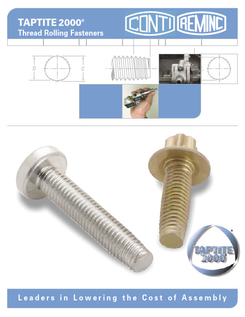
TAPTITE 2000®Thread Rolling FastenersL e a d e r s i n L o w e r i n g t h e C os t o f A s s e m b l y®®TAPTITE 2000®thread forming technology joins two unique concepts and advances fastener performance to new levels. TAPTITE ®2000™fasteners afford end-users with enhanced opportunities to reduce the overall Cost of Assembly .TAPTITE 2000®fasteners are designed to provide the benefits of prior Taptite ®fastener products with an innovative new thread design — the Radius Profile ™Thread . The proven Trilobular ™principle is maintained while incorporating the Radius Profile ™thread. The result is a new generation of TAPTITE 2000®fasteners, which provides excellentmechanical, assembly, and ergonomic characteristics surpassed by no other technology.®®2.Radius Profile ™ThreadTAPTITE 2000®HEAT TREATMENTTAPTITE 2000®bolts perform well in large diameter sizes in deep thread engagements.In the past, the limitations of case-hardened products restricted the exploitation of in-place cost savings for larger diameter Trilobular ™fasteners. However, TAPTITE 2000®screws and bolts are available with 3 different types of heat treatment: CORFLEX ®-I , CORFLEX ®N,and case hardened, making the fasteners adaptable to a wider variety of applications.CORFLEX ®-I Heat Treatment – CORFLEX ®-I TAPTITE 2000®bolts are neutral hardened to grade strength, metric 8.8, 9.8, 10.9 or any intermediate value.The thread forming zone is selectively induction hardened in order to form threads in untapped nuts.CORFLEX ®-I heat treatment allows T APTITE 2000®thread rolling bolts to provide in-place cost savings in large structural applications with strength, ductility and toughness equal to grade strength machine screws or bolts.CORFLEX ®-I heat treatment to Grade 10.9level is standard for TAPTITE ®2000™bolts in sizes M6 (1/4") and larger.CORFLEX ®-N Heat T reatment – CORFLEX ®-N TAPTITE 2000®fasteners are neutral hardened to grade 10.9 strength level. CORFLEX ®-N products are designed to be used in “soft white ” metals such as aluminum or zinc alloys. CORFLEX ®-N heat treatment can be specified for any size TAPTITE 2000®screws or bolts that are intended to be used in aluminum or zinc alloys.Case Hardening – Case hardening is the standard heat treatment for all TAPTITE 2000®screws in sizes M5 (#12) and smaller.N E W T O N SN m2000THREAD ROLLING BOLTBODIED THREAD ROLLING BOLT2000THREAD ROLLING BOLTBODIED THREAD ROLLING BOLT2000THREAD ROLLING BOLTSPEC.Lower Starting End Load TAPTITE 2000®fasteners require low axial end load to initiate thread forming.Higher Fail to Drive Ratio The higher, more uniform,fail to drive ratio of TAPTITE 2000®bolts provides a built-in safety factor against over-torquing.Prevailing Torque The Trilobular ™shape of TAPTITE 2000®provides “prevailing torque ”.Graph shows comparisonof a TAPTITE 2000®fastener with IFI 524 locking screw specification.NOTE: End load and fail to drive ratio graphs shown are based on average results recorded when testing an M8 x 1.25 size in unthreaded steel weld nuts having a 7.45mm diameter hole. Prevailing torque test per IFI-524.HEAT TAILORED FOR EXTRA TOUGHNESS Pin-point precision of high hardness zone in axial section of a CORFLEX ®-I fastener is shown by the crescent shaped areas in this chemically etched mount.®®Radius ProfileThread Design®®4.Metric Sizes (mm)Recommended pilot hole sizes for TAPTITE 2000®Screws and Bolts at various percentages of thread engagementEXAMPLE – The shaded area indicates that an M5 - 0.8 screw size in a 4.58 hole size provides 80% thread engagement. Because the above values are based on a linear relation between hole size and percentage thread engagement, the hole data becomes less accurate for engagements less than 70%.Pilot Hole Tolerance - in terms of radial thread engagement, min hole = nominal hole + 10%, max hole = nominal - 5%.Example: M8 - 1.25 in 6.0mm thick steel, nominal hole = 70% thread (7.43mm) per page 5 table. Min. hole = 80% thread (7.35mm), max hole = 65% thread (7.47mm).NOTE: All Data Tables in this brochure are for guidance purposes only.®®5.Recommended pilot hole sizes forTAPTITE 2000®Screws and Bolts in steel nut membersMetric Sizes (mm)APPLICATION DUTY CLASS - A general term used here to group material thickness in terms of screw diameters. For example, the average material thickness listed under ”medium-heavy ” equals 75% of the screw diameter.®®6.Recommended extruded pilot hole sizes in light-gauge steel for TAPTITE 2000®Screws and BoltsExtruding holes for fasteners in light-gauge steel nearly doubles the length of thread engagement over the original material thickness.Taptite 2000®screws and bolts develop almost twice the failure torque in extruded holes, providing maximum joint integrity.Example: The chart shows that for a M4 x 0.7 screw in a material thickness of 0.75mm the suggested hole diameter is 3.59mm. The corresponding “H ” dimension is the 1.35mm minimum, making the total length of engagement2.1mm minimum.H9A.®The minimum length of thread engagement should be equal to twice the diameter of the screw (to approach utilizing available screw strength). The hole diameter, to ensure optimum performance, shouldprovide for 65% to 75% thread engagement.Recommended pilot hole sizes for Aluminum or Zinc Alloy die castings for TAPTITE 2000® “SP ”™FastenersNote; “SP ”™designates Short PointREMINC/CONTIResearch Engineering & Manufacturing Inc.(REMINC) and Conti Fasteners AG (CONTI)have successfully marketed TAPTITE ®fastener technology internationally since 1961. Their success has been accomplished by licensing and training leading fastener producers worldwide.The technical program in the United States is under the direction of REMINC, located in Middletown, Rhode Island and in other countries under the direction of CONTI,situated in Baar, Switzerland.Although REMINC and CONTI are separate corporations and operate independently,each is dependent on the other for certain functional activities.AVAILABILITYCurrently there are 68 qualified producers located in 20 countries utilizing the Technical Knowhow, Patents, Trademarks, and Engineering and Marketing services ofREMINC/CONTI. These producers delivered a volume in excess of 17,000,000,000 pieces of Trilobular ™ fasteners in 2000, comprising a mix of products.The proprietary products available in the pro-gram are marketed and sold, not as fastener items but rather, as COST REDUCTIONS TO END-USERS OF ASSEMBLED PRODUCTS.The proprietary fasteners offered to theassemblers are the means to an end, ed to generate cost reductions while at the same time providing reliably tightened joints.ORDERING/SUPPLYWhen ordering from qualified Trilobular ™fastener producers, be sure in all cases to specify the TAPTITE 2000®brand name,thread size, nominal length, head and point style, strength grade if CORFLEX ®- N or CORFLEX ® -I is involved, any other special features required, finish, and of course, quantity.DISCLAIMER CLAUSEThe values shown in this brochure are for guidance only. They are not meant to be used for design criteria. Their use andreliance thereon for any purpose by anyone is entirely voluntary and at the sole risk of the user. REMINC/CONTI are not responsible for any loss, claim, or damage resulting from their use. Consult our application engineers or the application engineering department of one of our many qualified producers for your specific application data.TECHNICAL ASSISTANCEThis brochure contains basic information needed to achieve the cost savings potential of Trilobular ™fasteners.To obtain further assistance and a list of qualified producers, visit our website at or contact;In North America;REMINCT el: 401-841-8880Fax: 401-841-5008Email: reminc@ In Europe and all other countries;CONTI Fasteners AG;T el: +41 (0)41/761 58 22Fax: +41 (0)41/761 30 18Email: conti@contifasteners.chSERVICESA summary of the capabilities ofREMINC/CONTI in support of manufacturers:Technical Support•New Product Development•Research and Development Reports •Technical Manuals •Technical Reports•Technical Information Updates •Engineering Consultation•Computer Aided Design and Analysis •Engineering Training•Tooling Design and Procurement •Manufacturing Guidance•Manufacturing Cost Reduction •Metallurgical Analysis•End-User Application Guidance •Technical Training Seminars MARKETING SUPPORT •Application •Graphics Definition •Customer Product •Application Brochures Reports •Technical Liaison •Performance •Joint Customer Visits Documentation •Cooperative Studies •Sales Seminars •Trademark and •Audio/Video Patent Use Materials In addition to the above stated detail, REMINC/CONTI are positioned to provide:•Contract •Contract Joint Testing Analysis•Contract •Fastener Engineering Engineering Training•Consultation ActivitiesPatents and trademarks issued and/or pending worldwide.Albisstrasse 15, 6340 Baar (ZG) SwitzerlandTel: +41 (0)41/761 5822 Fax: +41 (0)41/761 3018Email: conti@contifasteners.chCONTI Fasteners AG55 Hammarlund Way, Tech II Middletown, RI 02842 USATel: 401-841-8880 Fax: 401-841-5008Email: reminc@Research Engineering & Manufacturing Inc.Copyright 2001, Research Engineering & Manufacturing Inc.11132000-AGS。
工艺规程-封面目录(AD系列)

总进气压力
压力表
6次/天
0.6+-0.05MPA
6
修整轮压力
压力表
6次/天
0.4+-0.05MPA
7
定位压力
压力表
6次/天
0.3-0.4MPA
1,。缝焊机数据应该与对应产品一致,并事先经过专人测试调整,每次缝焊机开启时候都婴孩进行校对:
更改序号
图纸版本
更改内容
日期
签名
日期:04/12/20
编制:
审批:
序号
检测项目
检测工具
频次
记录要求
备注
1
压力
压力表
4次/天
0.3MPa+0.05 MPa
更改序号
图纸版本
更改内容
日期
签名
日期:
编制:
审批:
页:1共1页
版本:05-01-15
上海均特汽车零部件有限公司
文件号:AD02-GY-40
重要度:B
设备:液压机
工位:4.0连杆与缓冲块座的压铆、
装缓冲块
工装:G-0302-002、G-0302-002-1、G-0302-002-2
2
2.0
清洗
AD01-GY-30
3
3.0
底阀总成装配
AD01-GY-31
3.1
底阀压入内筒
AD01-GY-40
4
4.0
连杆与缓冲块座的压铆、装缓冲块
AD01-GY-41
4.1
连杆与活塞装配
AD01-GY-50
5
5.0
注油
AD01-GY-60
6
6.0
压入导向衬套
DIN_3126_2004_01
A us dr u ck ea us de rd i g i t al e n D a t e n b a n k d e r D r äg e r w e r k A GL üb e c k . Ve rv i el f äl t i g un g l t . M e r k b l a t t 3 d e s D I N .-DQXDU'(876&+( 12501RUPHQDXVVFKXVV :HUN]HXJH XQG 6SDQQ]HXJH ):6 LP ',1Preisgruppe 9DIN Deutsches Institut für Normung e.V. • Jede Art der Vervielfältigung, auch auszugsweise, nur mit Genehmigung des DIN Deutsches Institut für Normung e. V., Berlin, gestattet.,&6:"9522810www.din.de X',10LWQDKPH 9HUELQGXQJHQ I U 6FKUDXEHQGUHKHUHLQVlW]H XQG9HUELQGXQJVWHLOH ±0D H'ULYH HQGV IRU VFUHZGULYHU ELWV DQG FRQQHFWLQJ SDUWV ±'LPHQVLRQV5DFFRUGV G¶HQWUDvQHPHQW SRXU HPERXWV GH WRXUQHYLV HW SLqFHV GH UDFFRUGHPHQW ±'LPHQVLRQV©Alleinverkauf der Normen durch Beuth Verlag GmbH, 10772 Berlin (UVDW] I U',1 XQG ',1www.beuth.de*HVDPWXPIDQJ 6HLWHQA us dr u ck ea us de rd i g i t al e n D a t e n b a n k d e r D r äg e r w e r k A GL üb e c k . Ve rv i el f äl t i g un g l t . M e r k b l a t t 3 d e s D I N .DIN 3126:2004-012VorwortDiese Norm wurde vom Normenausschuss Werkzeuge und Spannzeuge (FWS), Arbeitsausschuss G 1…Schraubwerkzeuge“ erarbeitet.Zusammenhang mit den von der International Organization for Standardization (ISO) herausgegebenen Internationalen Normen:Die Mitnahme-Verbindungen dieser Norm entsprechen in den Formen A bis H mit Ausnahme von Nut und Sprengring in Form D der von der International Organization for Standardization (ISO) herausgegebenen Norm:ISO 1173:2001, Assembly tools for screws and nuts — Drive ends for hand- and machine-operatedscrewdriver bits and connecting parts — Dimensions, torque testingund:Die Mitnahme-Verbindungen in den Formen I und K entsprechen der Norm:ISO 2352:2000, Assembly tools for screws and nuts — Spiral ratchet screwdriver ends — Dimensions Um die Beziehung zwischen den zusammengehörigen Maßen der Außen- und Innensechskante bzw. der Außen- und Innenflachkante deutlicher hervorzuheben, ist die Norm redaktionell so gestaltet, dass die Maßbuchstaben für die Aufnahmen nur mit ungeraden Indizes (1, 3, 5 ...) und die für die Schäfte mit geraden Indizes (2, 4, 6 ...) versehen sind.Um die Eckenmaße der Sechskant-Verbindungen gleichmäßig untereinander abzustimmen, wurden sie nach folgenden Gleichungen errechnet e 1max = 1,13 s 1max e 1min = 1,13 s 1min e 2min = 1,13 s 2 minÄnderungenGegenüber DIN 3126:1993-12 und DIN 7432:1988-05 wurden folgende Änderungen vorgenommen:a) Drillschraubendreher-Enden wurden aus ISO 2352:2000 übernommen;b) die Norm wurde redaktionell überarbeitet.Frühere AusgabenDIN 3126: 1967-03, 1971-03, 1976-04, 1986-12, 1993-12DIN 7432: 1969-05, 1976-04, 1998-05A us dr u ck ea us de rd i g i t al e n D a t e n b a n k d e r D r äg e r w e r k A GL üb e c k . Ve rv i el f äl t i g un g l t . M e r k b l a t t 3 d e s D I N .DIN 3126:2004-0131 AnwendungsbereichDiese Norm gilt für Mitnahme-Verbindungen für hand- und maschinenbetätigte Schraubendrehereinsätze sowie für die Antriebsspindeln von Maschinenschraubern. Sie soll die Austauschbarkeit der Werkzeug-Einsätze und Werkzeugträger sicherstellen.Angegeben sind nur die Unterscheidungsmerkmale der einzelnen Verbindungen. Konstruktive Einzelheiten,z. B. über die Halterung, bleiben dem Anwender der Norm überlassen.2 Normative VerweisungenDiese Norm enthält durch datierte oder undatierte Verweisungen Festlegungen aus anderen Publikationen.Diese normativen Verweisungen sind an den jeweiligen Stellen im Text zitiert, und die Publikationen sind nachstehend aufgeführt. Bei datierten Verweisungen gehören spätere Änderungen oder Überarbeitungen dieser Publikationen nur zu dieser Norm, falls sie durch Änderung oder Überarbeitung eingearbeitet sind. Bei undatierten Verweisungen gilt die letzte Ausgabe der in Bezug genommenen Publikation (einschließlich Änderungen).DIN EN 10270-1, Stahldraht für Federn — Teil 1: Patentiert-gezogener unlegierter Federstahldraht; Deutsche Fassung EN 10270-1:2001.A us dr u ck ea us de rdi g i t al e n D a t e n b a n k d e r D r äg e r w e r k A GL üb e c k . Ve rv i el f äl t ig un g l t . M e r k b l a t t 3 d e s D I N .DIN 3126:2004-0143 Maße, BezeichnungNicht angegebenen Einzelheiten sind zweckentsprechend zu wählen.Maße in MillimeteraHaltesystem nach Wahl des HerstellersBild 1 — Schaft Form ABild 2 — Aufnahme Form BBezeichnung eines Schaftes Form A von Nenngröße 3:Schaft DIN 3126 — A 3Bezeichnung einer Aufnahme Form B von Nenngröße 3:Aufnahme DIN 3126 — B 3Tabelle 1 — Schaft Form AMaße in Millimeters 1d 1d 3e 1l 1l 3l 5rFormNenn-größemax.min.h9h12max.min.min.02,0-4,00+min.332,963,633,393,3419,511,9 7,41A5,55,505,456,75,76,216,16241610,91,25Tabelle 2 — Aufnahme Form BMaße in Millimeters 2d 2e 2l 2l 4l 6FormNenn-größemax.min.D10min.± 0,12,00+04,0-33,063,023,63,4116,511,9 7,2B5,55,585,536,76,25211610,7A us dr u ck ea us de rd i g i t al e n D a t e n b a n k d e r D r äg e r w e r k A GL üb e c k . Ve rv i el f äl t i g un g l t . M e r k b l a t t 3 d e s D I N .DIN 3126:2004-015Nenngröße 4Maße in MillimeterNenngrößen 6,3, 8 und 12,5a 40°£ = £ 60°b80°£ > £ 120°Bild 3 — Schaft Form CBezeichnung eines Schaftes Form C von Nenngröße 8:Schaft DIN 3126 — C 8Tabelle 3 — Schaft Form CMaße in Millimeters 1d 3e 1l 1l 3rFormNenn-größemax.min.h12max.min.min.2,0-min.4 3,96 3,91— 4,48 4,4294—6,3 6,35 6,29 6,7 7,18 7,11118,28 7,93 7,87 8,2 8,96 8,9013,510,2C12,512,7012,6313,514,3514,2715,912,70,3A us dr u ck ea us de rd i g i t al e n D a t e n b a n k d e r D r äg e r w e r k A GL üb e c k . Ve rv i el f äl t i g un g l t . M e r k b l a t t 3 d e s D I N .DIN 3126:2004-016Maße in MillimeterNenngrößen 6,3, 8 und 12,5aHaltesystem nach Wahl des HerstellersBild 4 — Aufnahme Form DBezeichnung einer Aufnahme Form D von Nenngröße 8:Aufnahme DIN 3126 — D8Tabelle 4 — Aufnahme Form DMaße in Millimeters 2e 2l 2l 4FormNenn-größe max.min.min.± 0,12,00+4 4,04 3,994,51 8 46,3 6,45 6,397,2210 8,288,03 7,97912,510,2D12,512,8012,7514,414,912,7A us dr u ck ea us de rdi g i t al e n D a t e n b a n k d e r D r äg e r w e r k A GL üb e c k . Ve rv i el f äl t i g un g l t . M e r k b l a t t 3 d e s D I N .DIN 3126:2004-017Maße in MillimeteraHaltesystem nach Wahl des HerstellersBild 5 — Schaft Form EBild 6 — Aufnahme Form FBezeichnung eines Schaftes Form E von Nenngröße 11,2:Schaft DIN 3126 — E 11,2Bezeichnung einer Aufnahme Form F von Nenngröße 11,2:Aufnahme DIN 3126 — F 11,2Tabelle 5 — Schaft Form EMaße in Millimeters 1d 3e 1l 1l 3l 7rFormNenn-größemax.min.h12max.min.min.01,0-»min.6,3 6,35 6,294,7 7,18 7,11259,512,4(8)a 7,93 7,876,3 8,96 8,90275,41,22,4E11,211,1111,048,712,5612,4831,56,71,22,8aEingeklammerte Nenngröße möglichst vermeiden.Tabelle 6 — Aufnahme Form FMaße in Millimeters 2e 2l 2l 4FormNenn-größemax.min.min.max.1,00+ 6,3 6,45 6,397,22249,5(8)a 8,03 7,97925,55,4F11,211,2311,1612,61306,7aEingeklammerte Nenngröße möglichst vermeiden.Aus dr u ck ea us de rdi g i t al e n D a t e n b a n k d e r D r äg e r w e r k A GL üb e c k . Ve rv i el f äl t i g un g l t . M e r k b l a t t 3 d e s D I N .DIN 3126:2004-018Maße in Millimeter Maße in MillimeteraHaltesystem nach Wahl des HerstellersBild 7 — Schaft Form GBild 8 — Aufnahme Form HBezeichnung eines Schaftes Form G von Nenngröße 7:Schaft DIN 3126 — G 7Bezeichnung einer Aufnahme Form H von Nenngröße 7:Aufnahme DIN 3126 — H 7Tabelle 7 — Schaft Form GMaße in Millimeterd 1d 3e 1l 1l 3l 5rForm Nenn-größe f8h12max.min.min.± 0,2± 0,2min.G775,83,863,742620141,5Tabelle 8 — Aufnahme Form HMaße in Millimeterd 2e 2l 2l 4r 6FormNenn-größe H101,00+max.min.± 0,2H 774,12620,514A us dr uck ea us de rd i g i t al e n D a t e n b a n k d e r D r äg e r w e r k A GL üb e c k . Ve r v i el f äl t i g un g l t . M e r k b l a t t 3 d e s D I N .DIN 3126:2004-019Maße in MillimeterLegende1Form I Schaft mit V-förmiger Nut 2Prüfkugel oder -stift Æ 3 001,0-3Form I Schaft mit kreisbogenförmiger Ringnuta R 0,2 max. oder 0,2 max. ´ 45°bR 3 max. oder 3 ´ 45° max.Bild 9 — Schaft Form IBezeichnung eines Schaftes Form I der Nenngröße 7:Schaft DIN 3126 — I 7Tabelle 9 — Schaft Form IMaße in Millimeterd 1a 1c d 3el 1l 3FormNenn-größe01,0-05,020,0--02,0-02,0-min.± 0,15,55,52,613,97,72711,1773,31,65,49,23113,5I883,725,89,93113,5A us dr u ck eaus de rdi g i t al e n D a t e n b a n k d e r D r äg e r w e r k A GL üb e c k . Ve rv i el f äl t i g un g l t . M e r k b l a t t 3 d e s D I N .DIN 3126:2004-0110Maße in MillimeterLegende1Prüfkugel oder -stift Æ d 42Form KHülseBild 10 — Aufnahme Form KBezeichnung einer Aufnahme Form K der Nenngröße 7:Aufnahme DIN 3126 — K 7Tabelle 10 — Aufnahme Form KMaße in Millimeterd 2d 4a 2ghl 2l 4FormNenn-größe ± 0,05001,0-min.1,00+± 0,1max.± 0,15,55,61,22,74,722312,177,11,43,46,122714,6K 88,11,43,86,822714,6A us dr u ck e a u s d e r di g i t a l e n D a t e n b a n k d e r D r äg e r w e r k A GL üb e c k . V e r v i el f äl t i g un g l t . M e r k b l a t t 3 d e s D I N .DIN 3126:2004-01114 AusführungForm D Magnetische Ausführungen für handbetätigte Schraubendrehereinsätze dürfen ohne Bohrung für eine Kugel bzw. ohne Nut für einen Sprengring sein.5 DrehmomentprüfungDie Verbindungsteile dürfen nach Beanspruchung mit den Prüfdrehmomenten keine bleibende Verformung oder sonstige Beschädigungen, z. B. Risse, Brüche, aufweisen, die die Verwendbarkeit beeinträchtigen.Tabelle 11 — PrüfdrehmomentwertePrüfdrehmomentN × mFormNenngrößemin.37,6A, B5,5474186,3718144C, D12,54786,3718144E, F 11,2396G, H 7255,58710I, K812LiteraturhinweiseISO 1173, Assembly tools for screws and nuts — Drive ends for hand- and machine-operated screwdriver bits and connecting parts — Dimensions, torque testing.ISO 2352, Assembly tools for screws and nuts — Spiral ratchet screwdriver ends — Dimensions.。
DBL_5471_2007-05
May 2007Mercedes-Benz Supply SpecificationTrim and molded padded parts for vehicleinteriors (composite parts) DBL 5471 BQF availableAdditional DaimlerChrysler Standards required:DBL 5306, DBL 5307, DBL 8585, MB Special Terms .Supersedes edition: 03.2000 Refer to Section Changes: Page 5Fortsetzung Seite 2 bis 9Issued by: DaimlerChrysler AG70546 Stuttgart Standards (GR/EQS) Technical responsibility (name): HöfelDepartment: PWT/VWK Plant: 050 Phone: +49(0)7031 90 83298 HPC: F105 Technical coordination by PWT Plant 59, Department PWT/VWK Name: Dr. Schuh Telephone +49(0)7031 90 44270HPC: 059 X 685 Confidential! All rights reserved. Distribution or duplication in part or in whole without prior written approval of DaimlerChrysler AG is not permitted.In case of doubt, the German language original should be consulted as the authoritative text.Overview of product versions:Table 1All product versions up to PV 89 not for new designsFor technical data, if required, refer to DBL 5471, edition March 2000Product versions Solar irra-diation Temperature exposureExamples(The PV indicated on the drawing shall apply) .90 is replaced by PV 95.91 is replaced by PV 92.92 partly 90°C -- - - - - - - - - - - - - - - - - - - - Trim rear space Roadster Roof grab handlesCenter armrestsDoor arm rests, door handles, door pocket lidsTrim station wagon trunk completeSeat gap cover insideMirror triangleEdge guardsTunnel trimHousing with stowage trayTrim for commercial vehicle cab (e.g. roof trim)Sun visorsInstrument panel lower parts (knee bolster)A, B, C pillar trimHead restraint driverDoor trim with waistlineSeat cushion, seat backrestsRoof frame trim, roof frame elements convertibleMolded ceiling, sliding sunroofGlove box lidAir bag assy.93 is replaced by PV 92.94 full 120 °C -- - Instrument panel upper section Rear shelf and speaker grilleRear head restraint.95 without 80°C -- - -Trunk lining Seat facings, seat gap covers outside, driver's backrest liningFloor area occupant compartment, footrestDoor pockets, central door panels, in-door speaker grillesNote:In the case of systems (assemblies), the PV with the higher temperature shall be selected for testing.DBL 5470 has been superseded by DBL 5471 (05.92).Page 2DBL 5471 : May 2007Abbreviated designation : e.g. Composite material DBL 5471.901. APPLICATIONSThis Specification is intended to facilitate the accelerated aging of assembly components by means of different storage parameters. It specifically applies to the assessment of surface materials of trim and molded padding used in vehicle interiors incl. the luggage compartment. Non-laminated plastic compo-nents shall be aged in accordance with DBL 5471 and assessed visually. In addition, DBL 5404 shall be observed for these components. Painted plastic parts shall be assessed according to DBL 7384.2. MATERIALSThe technical values of all starting materials shall correspond to the individual material DBLs, require-ments specifications and drawings.3. PROPERTIES3.1General requirements- - In line with the specifications of the Quality Management unit of the receiving plant, the components shall be free of manufacturing defects of any kind which would impair the processing and utilization properties or the appearance (e.g. free from release agents). Cleaning agents used during the manufac-turing process shall not cause any material/surface damage.Trim:The bond between the surface material and the substrate shall extend across the whole surface and shall be uniform, sufficiently strong and resistant to aging. The surface material shall be turned over and glued at the outside edges with sufficient strength and without disturbing overlaps. The pull-off force of any glued-on, riveted or integrated attachment or assembly parts (holders, clips or similar) shall corre-spond to the values indicated on the drawing, and the values shall be indicated in the ISIR.- Moldedpaddedparts:These shall be molded with correct dimensions in accordance with the drawing or the functional specifi-cations and demonstrate the specified hardness (indentation depth). The foam expansion shall be even and without noticeable pockets. The foam shall have completed all reactions after a storage time of the molded padded part of 24 hours at room temperature, i.e. it shall not be tacky nor brittle. The bond be-tween cover material and foam as well as between foam and substrates shall be firm enough to ensure that no separation can occur during assembly or use (e.g. as a result of release agent residues). This requires appropriate conditioning of the surface of the materials. The surfaces of the molded padded parts shall correspond to the specified design pattern.- The availability of a certificate of testing in accordance with the following method is specified as an over-riding requirement for adherence to the emission values for interior trim materials: VDA 278; threshold values DBL 8585.The user is responsible for checking whether the version in his possession is the latest version. Forinquires on threshold values, please apply to VDA278.DC-Info@.In particular in the case of substances listed in DBL 8585 Section 2.3, the supplier is required to con-tinuously minimize the concentration and emission at least in accordance with the state of the art, even when values have fallen below the required DBL threshold values.-In installed condition, the materials used shall comply with the following requirements when tested in accordance with the test instruction: "Formteile für den Fahrzeuginnenraum - Bestimmung der Abgabe von Formaldehyd, Ammoniak und Phenolen - Messverfahren in der 1 m³- Kammer“ (draft October 1994, issued by Arbeitskreis "Kfz.-Formteile - einfache Prüfmethoden“ under the leadership of FhG-WKI, Bien-roder Weg 54 E, D-38108 Braunschweig):- Formaldehyde emission: initial value max. 0,2 ppm, in equilibrium max. 0,05 ppm- Phenol emission: max. 0,04 ppm- Ammonia emission: minimalPage 3DBL 5471 : May 2007 Measurements shall be carried out on finished parts under the following testing conditions:- Temperature 65 °C- Relative humidity 11 %- Cabinet load 2 m² per m3- Change of air 0,5 h-1The consistency of production with regard to formaldehyde release shall be tested by means of a simple method and documented, e.g. bottle method (determination of formaldehyde release of molded parts by the bottle method, VDA recommendation 275- DKF, Ulrichstr. 14, D-74321 Bietigheim) or gas analysis method DIN-EN 717-2 (was: DIN 52 368 - Beuth Verlag GmbH, D-10772 Berlin). It is a condition, how-ever, that this value is determined already for the initial sample. For this reason, it shall also be indi-cated on the acceptance test certificate.3.2 Shape, dimensions, cut-outs and markingsIn accordance with drawing and/or template.3.3 ColorIn accordance with order, approval, reference sample and other specifications (DE/QM).3.4 GrainIn accordance with order MBN 31 0304.TECHNICAL DATARefer to Table 2, pages 6 to 9.METHODS5. TESTDIN/EN/ISO (refer to Table 2) or DBL 5306, Part II and DBL 5307.5.1 Separating force for laminated parts (cover material/substrate)The test shall be carried out in analogy with the separation test in accordance with DIN 53 357 immedi-ately after the specified storage periods. Test specimens shall be taken in longitudinal, transverse and diagonal directions and shall provide a representative cross-section of the complete part and shall bedocumented in the ISIR.The test specimens shall be prepared by sawing out pieces approx. 70 mm wide and approx. 200 mm long. For testing the separating force, cut the surface material through to the substrate 50 ± 1 mm wide with a knife in the longer direction of the test specimen.5.2 Foam adhesion for molded paddings (excerpt from DBL 5306.16)Strips 50 mm wide shall be cut into the narrow side of the molded padding, and the surface material(e.g. deep drawn films, molded skins) shall be pulled off at an angle of approx. 120° and at a rate ofapprox. 100 mm/5 s constantly and without sudden movements. The area-based foam adhesion on the reverse of the pulled-off materials and the surface of the substrate shall be assessed. As a representa-tive average, at least 75 % of the total surface of the molded padding shall be pulled off from variouslocations and assessed. Adhesion values are specified in the specific material DBL. Each individualstrip shall be assessed; the result shall be calculated by averaging. No individual strip shall lie morethan 50% below the foam adhesion. Where the visual foam adhesion between the molded skin and the foam yields a result lower than 75%, compliance can be proven by indicating the separating force value in N. Attach a spring balance (compression-tension measuring unit 0 to 50 N) to the test strip and de-termine the separating force under the test conditions indicated above. The test result shall not fall be-low the lower threshold value required in the specific material DBL (10 N/5 cm strip width). The test shall be performed on components which have been stored at 23 ± 5 °C for at least 48 h after foaming orwhich have been subjected to heat storage.Page 4DBL 5471 : May 20075.3 Climatic resistance testsAssessmentcriteria: The parts shall not demonstrate any changes interfering with the application in comparison with the as-supplied state (e.g.warping, flattening, deflection, shrinkage or extension of thefinished parts, detachment of the surface material and of thefastening and making-up parts, glue embrittlement, blistering,impressions and piercing, waviness, brittleness and cracking ordiscoloration (assessment in accordance with ISO 105-A02),tackiness, marked glossiness and grain flattening of thesurface material, marked swelling, spalling, layer and fiberseparation of the substrate or similar). Weld joints shall notseparate.S = Focus point test (see DBL 5306.104) shall always be performed.Temperature requirements deviating from the functional specification:There is a temperature differential between the surface and substrate in the vehicle. For climatic cham-ber storage, the requirements profile for the surface is higher.The components are stored unassembled and shall therefore not be used for the assessment of dimen-sional requirements.Test sequence:1.2. 3. 4. Alternating atmospheres All constant atmospheresSolar simulationLow temperature storage5.4 More precise indication of color fastness to light (hot light fastness) and aging (hot light aging) to artifi-cial light at high temperatures in accordance with DIN / EN / ISO 105-B06.Exposure conditions: 3 (normal); irradiance 1,2 W/m² (420nm)For type of apparatus C, filter system BS/SL shall be used.Color fastness (HLF)- Determination of end point: Exposure to ∆E 4,3+/-0,4 of reference 6 (exposed/to covered). Colormeasurement of reference with white reference tile as substrate.- Assessment: Comparison exposed specimen with original specimen for light sourceD65.Assessment with blue scale (references).Determination of aging (HLA)- Determination of end point: as for HLF, but with several consecutive cycles.For each cycle, a new reference 6 shall be used.- Assessment: Comparison exposed specimen with original specimen for light sourceD65.Assessment with gray scale in accordance with DIN EN 20105-A025.5 Abrasion resistance*1. To be tested in as-supplied condition2. To be tested following testing according to 5.3. in sequence 1, 2, 3 (item 3 only for PV 94)3. To be tested following hot light aging (HLA)4. To be tested on leather-faced parts following testing according to5.3 in sequence 1, 25. To be tested on leather-faced parts following hot light aging (HLA)5.6 Sun cream test* Required components: instrument panel, upper and lower sections, center consoles, door linings. Onlyfor films andmolded skin surfaces. Testing in as-supplied condition, not in aged condition.*) For Sections 5.5 and 5.6 also refer to DBL 5399Page 5DBL 5471 : May 20075.7 The contact staining problem shall be assessed in accordance with PAPP PWT 7329.5.8 The corrosion behavior of metallic components shall be assessed in accordance with test instruction PBVWT 217.6.DUTIES OF THE SUPPLIERRefer to MercedesBenz Special Terms No. 13 and No. 16, Purchase Conditions for Production Materi-als and Spare Parts for Motor Vehicles.7. SAMPLESRefer to MercedesBenz Special Terms No. 13.8. DELIVERIESRefer to MercedesBenz Special Terms No. 13 and DBL 5306, Section 104.9. MARKINGRefer to MercedesBenz Special Terms No. 4, No. 24, No. 27 and DBL 5306, Section 105.10. PACKAGING, FORM OF SUPPLY AND DELIVERY CONDITIONSRefer to Mercedes-Benz Special Terms No. 30.Freedom from silicones shall be assured in general.11. STORABILITYRefer to DBL 5306, Section 107.INSTRUCTIONS12. SPECIALRefer to DBL 5306, Section 108.13. COMPLAINTSRefer to MercedesBenz Special Terms No. 16 and Purchase Conditions for Production Materials and Spare Parts for Motor Vehicles.14. ENVIRONMENTAL PROTECTION REGULATIONS/INDUSTRIAL SAFETYRefer to MercedesBenz Special Terms No. 30, No. 36 and DBL 8585 Negative substance list for theselection of materials.Changes:PV 93 deleted, PV 92, PV 94 and PV 95 revised.Revision 01.2006Page 6DBL 5471 : May 2007Table 2:4. Technical data Product version requirements Test method90 91 92 93 94 95Conditioning of parts Parts shall only be tested after the reaction of the glue or foam has been completed (refer to data sheets). Ifno indications are made: storage 48 h min. at room temperature.General requirements for allalternatingatmospheres Time/temperature/relative humidityNote: All times are holding times. Tolerances: Temperature ± 1 K; relative humidity ± 3 %; rate of change of temperature, heating: approx. 1,5 K/min, cooling: approx. 1,5 K/min; crossover point temperature/relative hu-midity in heating and cooling phases at 40°C max./ 40% r.h. max.The recorded diagrams shall be documented for leather surfaces.Climatic resistance storage For requirements text, refer to Section 5.3, page 4 4.1Alternatingatmospheres4.1.1 Dry-warm/humid-cold(warm climate cycle test A)Film, skin andtextilesurfaces - - - - - S:+ 6 cycl. {2h / 80°C / max. 20%+ 1h / 23 ± 3°C / 50 ± 15%}Leathersurface - - - - - S:+30 cycl. {4h / 10°C / 92%+ 2h / 80°C / max. 20%}for series production monitoring10 cycl.4.1.2 Dry-warm/humid-cold(warm climate cycle test B)Film, skin and textile surfaces S:+S:+S:+S:+ fol-lowed by 2h 105 °C - -6 cycl. {2h / 90°C / max. 20%+ 1h / 23 ± 3°C / 50 ± 15%}Leathersurface S:+S:+S:+S:+ fol-lowed by 2h 105 °C - -30 cycl. {4h / 10°C / 92%+ 2h / 90°C / max. 20%}for series production monitoring10 cycl.4.1.3 Dry-hot/humid-cold(hot climate cycle test)Film, skin andtextilesurfaces - - - - S:+- 6 cycl. {2h / 120°C / max. 20%+ 1h / 23 ± 3°C / 50 ± 15%}Leathersurface - - - - S:+- 30 cycl. {4h / 10°C / 92%+ 2h / 105°C / max. 20%}for series production monitoring10 cycl.UPage 7DBL 5471 : May 2007 4. Technical data Product version requirements Test method(continued) 90 91 92 93 94 954.2 Constant atmospheres4.2.1 Dry-warm endurance test A(warm temperature test)- - - - - S:+7d / 80 °C / max. 20%4.2.2 Dry-warm endurance test B(warm temperature test)S:+S:+S:+S:+- - 7d / 90 °C / max. 20%4.2.3 Dry-hot endurance test(heat test)Film, skin andtextilesurfaces- - - - S:+- 7d / 120 °C / max. 10% Leathersurface S:+7d / 105 °C / max. 10%4.2.4 Humid-warm agingFilm, skin and textile surfaces, not for parts with leather surfaces S:+S:+S:+S:+S:+S:+21d / 40 °C / 92%4.3 Changeincolorafter climate storage 4.1 and 4.2Minimum Rating 4 - 5 4 - 5 4 - 5 4 - 5 4 - 5 4 - 5DIN/EN 20105-A024.4 Solar simulation DIN 75 2204.4.1 Indoor 1 - - - - + - Indoor 1 dry climate4.5 Color change after solarafter solar simulation 4.4Minimum Rating - - - - 4 -ISO 105-A024.6 Cold resistance DBL 5306.7.3;storage 24 h at -30 ±2 °C,4.6.1 Ball drop test + + + + + + Drop height: 200mm4.7 Hardness test The required indentation depth is specified on the relevant drawing for theindividual parts and shall be documented in the ISIR.DBL 5306.15.2 ????UPage 8DBL 5471 : May 20074. Technical data Product version requirements Test method(continued) 90 91 92 93 94 954.8 Layer separation force *Minimum N Refer to Sectio 5.1.n4.8.1 For substrates with rough surface (e.g. hardboard, pressed non-woven fabric etc.)and for covering materials with very high elongation (min. 45% elongation at 50N; e.g. knitted fabric) *If the separating forces are not reached, a waiver shall be agreed with DC and docu-mented. These shall be recorded in the ISIR.4.8.1.1 after storage in standard atmosphere 15 15 15 15 15 154.8.1.2 after climatic storage S: 12S: 12S: 12S: 12S: 12S: 12For storage, refer toSection 4.1, 4.2, 4.4 4.8.2 For substrates with smooth surface (e.g. injection-molded ABS, PUR-GF)4.8.2.1 after storage in standard atmosphere20 20 20 20 20 20but for film 50 50 50 50 50 504.8.2.2 after climatic storage S: 15S: 15S: 15S: 15S: 15S: 15For storage, refer tobut for film S: 50S: 50S: 50S: 50S: 50S: 50Section 4.1, 4.2, 4.44.9 Surface adhesion for molded padding Minimum %Section5.2,DBL5306.16; for storage, refer to4.9.1 Cover material to foam S: 75S: 75S: 75S: 75S: 75S: 75Section 4.1, 4.2, 4.4 4.9.2 Substrate to foam S: 75S: 75S: 75S: 75S: 75S: 754.10 Burningtest S: Fulfillment of requirements in accordance with DBL 5307, product ver-sion 10 / 20.DBL 5307.5.1 or 5.24.11 Abrasion resistance, only for film,skin or plastic surfacesMinimum Rating4.11.1 dry 4 4 4 4 4 4 DBL 5306.4.1 Refer to Section5.54.11.2 wet4.11.3 *MB stain remover 4.11.4 MBplasticscleaner 4.11.5 MBglasscleaner 3-43-43-43-43-43-43-43-43-43-43-43-43-43-43-43-43-43-43-43-43-43-43-43-4* 5 strokes without additionalweightBQF 7528.00BQF 6960.204.12 Sun cream testMaximum Rating 1 1 1 1 1 1 PAPP/PWT 7328 Refer to Section 5.64.13 Scratch resistance only for film,skin or plastic surfaces The surface shall demonstrate no or only a small scribing effect when mar-king with a finger nail.DBL 5306.3.14.14 Scratch exposure of surface withchisel, only for flexible cellular TPO and PVC sheeting No violation of surface.DBL 5306.3.2; for total load, referto individual material DBL, oth-erwise 1600gUPage 9DBL 5471 : May 2007 4. Technical data Product version requirements Test method(continued) 90 91 92 93 94 954.15 Color fastness (HLF)Minimum blue scale Rating 6 6 6-7 6-7 6-7 6DIN/EN/ISO 105-B064.16 Aging (HLA)Minimum gray scale Rating - - 4 periods 4 periods 4 periods3-4 -For test methods refer to Section5.4Requirement:Possible deviationCover product DBL shall determine the requirements for the finished part with regard to the rating and number of periods.If cover product DBL-PV is better in rating (with a number of periods of at least 4) than in the corresponding PV of DBL 5471, the following criteria shall apply:u Number of periods as specified in cover productDBL.u Rating max. deviation 0,5 downwards.If no cover product is specified, rating and number of periods of corresponding PV of DBL 5471 shall apply.4.17Emission analysis4.17.1 VOC value µg/g (ppm) 4.17.2 FOG value µg/g (ppm)Target value: ≤ 100Target value: ≤ 250DBL 8585VDA 278*Critical individual substances shall not exceed the limit/target valuesindicated in DBL 8585, Section 2.3.4.18 Odor testMaximum Rating 3 3 3 3 3 3 VDA 270; depending on compo-nent size4.18 Fogging test For the composite, the fogging values specified in the relevant DBL of thesurface materials apply. The relevant approval shall be available alreadybefore the approval of the relevant parts. If no allocation is possible or novalue has been specified, the following shall applyFogging test: Quantity of condensable substance: Maximum 1,0 mgFor the substrate materials the values specified in the DBL, if available,shall apply. If no allocation is possible or no value has been specified, thefollowing shall applyFogging test: Quantity of condensable substance: Maximum 2,0 mgDIN 75 201 * In the event of deviations, the value specified in the individual material DBLs shall apply.U。
ETA 2836-2机芯装配图(原厂)
Eye protection is obligatory for all operations / work on the movement!
ETA SA décline toute responsabilité en cas de dommages du non respect de cette "Communication technique".
La protection des yeux est obligatoire pour toutes les interventions / tous les travaux sur le mouvement!
Für sämtliche Arbeiten am und mit dem Uhrwerk ist ein Augenschutz obligatorisch!
Wassergefährdende Stoffe müssen in geeigneten Behältern aufbewahrt, transportiert, aufgefangen und entsorgt werden. Diese dürfen nicht den Boden belasten oder in die Kanalisation gelangen!
COMMUNICATION TECHNIQUE TECHNISCHE MITTEILUNG TECHNICAL COMMUNICATION
11 ½´´´ ETA 2836-2
CT 2836-2 FDE 481924 11
24.05.2011
11 ½´´´ Ø 25,60 mm Hauteur sur mouvement Réserve de marche Nombre de rubis Angle de levée du balancier Fréquence Höhe auf Werk Gangreserve Anzahl Rubine Hebungswinkel der Unruh Frequenz Movement height Running time Number of jewels Angle lift of balance Frequency 5,05 mm 38 h 25 50° 28’800 A/h
研发工程与制造有限公司与联合公司TAPTITE 2000螺纹手册说明书
This report is Copyrighted in 2013 by Research Engineering & Manufacturing Inc.E-mail:***************** CONTI Fasteners AG Albisstrasse 15E-mail:***********************® Licensees®, TAPTITE II ®, TYPE-TT ®, DUO-TAPTITE ®, CORFLEX ®, PLASTITE ® POWERLOK ®,®, KLEERLOK ®, FASTITE ®, TAPTITE 2000®, TYPE TT 2000®, TAPTITE 2K ®, TYPE TT 2K ®REMINC/CONTI TAPTITE 2000® SCREWSEND-USER SPECIFICATIONSPR-180January 2008 Revised May. 2019REMINC/CONTITAPTITE 2000® SCREWSEND-USER SPECIFICATIONSINTRODUCTIONThis document provides end-users of TAPTITE 2000® screws dimensional and material information to be used as a uniform standard for TAPTITE 2000® screws. End-users may use this copyrighted material to create their own in-house TAPTITE 2000® standards. This information is intended for use only with TAPTITE 2000® and other genuine TAPTITE®products and prior notification to and permission from REMINC/CONTI is required before incorporating this copyrighted material into any company documents.SCOPE²TAPTITE 2000® screws are high performance thread rolling (forming) screws which form internal threads in nut members, eliminating the need for pre-tapping the nut member, thus lowering the in-place cost of assembly. TAPTITE 2000®screws provide an improved level of overall performance over previous TAPTITE®designs. TAPTITE 2000®screws are characterized by having a unique or multiple TRILOBULAR™ configuration and a unique Radius Profile™ thread form.²Standard TAPTITE 2000® screws have two general configurations. Screws M5 and smaller have a four thread tapered lead with a unique optimum TRILOBULAR™ configuration. Standard TAPTITE 2000®screws M6 and larger have two stabilizing threads which align the screw in the hole and three tapered threads and dual TRILOBULAR™ geometry.²TAPTITE 2000® screws are available with three different heat treatments to suit various nut member materials. ²Standard TAPTITE 2000® screws, M5 and smaller, are case hardened for use in steel applications.²Standard TAPTITE 2000® screws, M6 and larger, are supplied with CORFLEX®-‘I’ heat treatment which provides a neutral hardened screw to any specified grade strength level with a selectively hardened point for thread forming into steel nut members.²Although CORFLEX®-‘I’ heat treatment is recommended for M6 and larger sizes, TAPTITE 2000® screws of any size can be supplied case hardened.²TAPTITE 2000®screws, of any size, which are to be used in soft metals such as aluminum, zinc or magnesium can be heat treated as CORFLEX®-‘N’ screws. This heat treatment is basically neutral hardening to achieve the desired grade strength level. Decarburization is not allowed.²TAPTITE 2000® “SP”™ screws have a short point suitable for use in blind holes in aluminum, zinc and magnesium and are supplied with CORFLEX®-‘N’ heat treatment.²TAPTITE 2000® “CA”™ screws can be supplied with a cut-off or non-cut-off style point. These screws are hole finding and they can be supplied with the same heat treatment as standard TAPTITE 2000® screws dependent on the various nut member materials.²All TAPTITE 2000® screws can be supplied with standard coatings and lubricants.SIZE PITCH LIMITSC D MR0.8 0.20Max0.800 0.780 Min 0.770 0.745 MR1.0 0.25Max1.000 0.975 Min 0.955 0.924 MR1.2 0.25Max1.200 1.175 Min 1.155 1.124 MR1.4 0.30Max1.405 1.375 Min 1.355 1.317 MR1.6 0.35Max1.61 1.58 Min 1.53 1.49 MR1.8 0.35Max1.81 1.78 Min 1.73 1.69 MR2.0 0.40Max2.01 1.97 Min 1.93 1.88 MR2.2 0.45Max2.21 2.17 Min 2.12 2.06 MR2.5 0.45Max2.52 2.48 Min 2.43 2.37 MR3.0 0.50Max3.02 2.97 Min 2.93 2.87 MR3.5 0.60Max3.52 3.46 Min 3.42 3.35 MR4.0 0.70Max4.02 3.95 Min 3.92 3.83 MR4.5 0.75Max4.52 4.45 Min 4.41 4.32 MR5.0 0.80Max5.02 4.94 Min4.914.81Notes: Ls = Screw length ordered. Tolerance per customer requirements.Dimensions shown are before plateSIZE PITCH LIMITS C DMR6 1.00 Max 6.03 5.93Min 5.90 5.78MR7 1.00 Max 7.03 6.93Min 6.90 6.78MR8 1.25 Max 8.03 7.91 Min 7.87 7.71MR9 1.25 Max 9.03 8.91 Min 8.87 8.71MR10 1.50 Max 10.03 9.88 Min 9.85 9.66MR12 1.75 Max 12.04 11.87 Min 11.83 11.61MR14 2.00 Max 14.04 13.84 Min 13.81 13.56MR16 2.00 Max 16.04 15.84 Min 15.81 15.56MR18 2.50 Max 18.04 17.79Min 17.76 17.45MR20 2.50 Max 20.04 19.79Min 19.76 19.45Notes: Ls = Screw length ordered. Tolerance per customer requirements.Dimensions shown are before plate.SIZE PITCH LIMITSC D MR1.0 0.25Max1.000 0.975 Min 0.955 0.924 MR1.2 0.25Max1.200 1.175 Min 1.155 1.124 MR1.4 0.30Max1.405 1.375 Min 1.355 1.317 MR1.6 0.35Max1.61 1.58 Min 1.53 1.49 MR2.0 0.40Max2.01 1.97 Min 1.93 1.88 MR2.5 0.45Max2.52 2.48 Min 2.43 2.37 MR3.0 0.50Max3.02 2.97 Min 2.93 2.87 MR3.5 0.60Max3.52 3.46 Min 3.42 3.35 MR4.0 0.70Max4.02 3.95 Min 3.92 3.83 MR5.0 0.80Max5.02 4.94 Min 4.91 4.81 MR6.0 1.00Max6.03 5.93 Min 5.90 5.78 MR8.0 1.25Max8.03 7.91 Min 7.87 7.71 MR10.0 1.50Max10.03 9.88 Min 9.85 9.66 MR12.0 1.75Max12.04 11.87 Min 11.83 11.61 MR14.0 2.00Max14.04 13.84 Min 13.81 13.56 MR16.02.00Max16.04 15.84 Min 15.81 15.56Notes: Ls = Screw length ordered. Tolerance per customer requirements.Dimensions shown are before plate.SIZE PITCH C D Cp P LIMITS SIZE PITCH C D Cp PMax Ref. Max Ref.MR0.8 0.20 0.800 0.7800.12 1.10MaxMR4.5 0.754.52 4.451.96 4.13 0.770 0.745 Min 4.41 4.32MR1.0 0.25 1.000 0.9750.15 1.38MaxMR5.0 0.805.02 4.942.29 4.40 0.955 0.924 Min 4.91 4.81MR1.2 0.25 1.200 1.175 0.35 1.38 Max MR6.0 1.00 6.03 5.93 2.62 5.501.155 1.124 Min 5.90 5.78MR1.4 0.30 1.405 1.375 0.38 1.65 Max MR7.0 1.00 7.03 6.93 3.62 5.501.355 1.318 Min 6.90 6.78MR1.6 0.35 1.61 1.580.41 1.93MaxMR8.0 1.258.03 7.913.76 6.88 1.53 1.49 Min 7.87 7.71MR1.8 0.35 1.81 1.780.61 1.93MaxMR9.0 1.259.03 8.914.76 6.88 1.73 1.69 Min 8.87 8.71MR2.0 0.40 2.01 1.97 0.64 2.20 Max MR10.0 1.50 10.03 9.88 4.91 8.251.93 1.88 Min 9.85 9.66MR2.2 0.45 2.21 2.17 0.67 2.48 Max MR12.0 1.75 12.04 11.87 6.06 9.632.12 2.06 Min 11.83 11.61MR2.5 0.45 2.52 2.480.98 2.48MaxMR14.0 2.0014.04 13.847.21 11.00 2.43 2.37 Min 13.81 13.56MR3.0 0.50 3.02 2.971.312.75MaxMR16.0 2.0016.04 15.849.21 11.00 2.93 2.87 Min 15.81 15.56MR3.5 0.60 3.52 3.46 1.47 3.30 Max MR18.0 2.50 18.04 17.79 9.50 13.753.42 3.35 Min 17.76 17.45MR4.0 0.70 4.02 3.95 1.63 3.85 Max MR20.0 2.50 20.04 19.79 11.50 13.753.92 3.83 Min 19.76 19.45TAPTITE 2000® SCREWS Case Hardened Material, Mechanical & Perfor mance RequirementsSection 1: SCOPE1.01This section specifies the requirements for case hardened and tempered TAPTITE 2000® screwsintended to be used in steel with a hardness up to 250HV. The requirements stated are intended toqualify TAPTITE 2000® screws as meeting their intended requirements and are not associated withspecific applications.1.02REFERENCES:ISO-898/1 Mechanical PropertiesISO-6507 Hardness Test – Vickers TestSection 2: MATERIALS2.01Cold heading quality fully killed steel wire per SAE J1237Note: For TAPTITE® fasteners a minimum carbon content of 0.18 is recommended to insurerequired mechanical properties are met.Section 3: MECHANICAL PROPERTIES3.01Heat TreatmentScrews shall be heat treated in a gas carburizing or carbonitriding system, quenched in suitable mediato create a martensitic microstructure. Minimum tempering temperature shall be 340°C minimum.Case Hardness: HV 280 – HV 370Surface Hardness: HV 450 minimumCase Depth: M2 – 3.5 0.05mm – 0.18mmM4 – 5.0 0.10mm – 0.23mm3.02Torsional Strength TestMinimum Torsional Strength (Torque in Nm)M1.0 0.06M2.0 0.60M2.5 1.20M3.0 2.20M3.5 3.50M4.0 5.20M4.5 7.50M5.0 10.503.03DuctilityScrews should withstand a wedge angle of 7° without head separating from shank.3.04Thread Forming CapabilityScrews shall form a mating thread in specified steel test plates and screw thread shall display nosigns of deformation. The internal thread formed shall be capable of accepting a standard 6gtolerance machine screw.3.05Hydrogen Embrittlement TestScrews with electroplated finishes must withstand being in a tightened state for 24 hours and thenwithstand a retightening.Section 4: TEST METHODS4.01Core HardnessCore hardness shall be determined at the mid-radius of a transverse section through the screw takenat a distance sufficiently behind the point of the screw to be through the full minor diameter. Thetest shall comply with ISO 6507.4.02Case Hardness TestFor routine quality control purposes (where case depth and geometry of screws permit), casehardness may be measured on end, shank or head using Vickers Hardness procedure in accordancewith ISO-6507. Hardness tests shall be made on plain finish or plated screws after the finish hasbeen removed.As an alternate method or for referee purposes a micro-hardness instrument can be used. In suchcases, measurements shall be made on the thread profile of a properly prepared longitudinalmetallographic specimen.4.03Case Depth TestCase depth shall be measured at midpoint between crest and root on the thread flank using industryaccepted methods.4.04Torsional Strength TestThe screw shall be clamped in place using a threaded or non-threaded clamping device so thatclamped threads are not damaged. Three threads as a minimum must protrude beyond the top ofthe clamping device. Using a torque measuring device, torque shall be applied until the screwfractures. The torque required to cause fracture is the torsional strength. Fracture must occur inthe exposed threads and not in the clamped portion.On case hardened screws, sizes M5 and smaller, torsional strength testing is required in lieu oftensile testing.4.05Ductility TestThe sample screw shall be inserted into a hole in a hardened, 7° angle wedge block, having a holesize 0.5 to 1.0mm larger than the nominal screw size. An axial compressive load shall be appliedagainst the top of the screw until the plane of the underhead bearing surface is bent permanently to7° with respect to a plane normal to the axis of the screw.It is acceptable to induce the 7° permanent deformation using a hand-held hammer.4.06Thread Forming Capability TestSample screws shall be driven into holes in specified steel test plates until an internal thread of fullmajor diameter is formed completely through the full thickness of the test plate. The driving speedshall not exceed 300rpm. Recording the maximum torque required to form the internal thread isoptional. The use of a lubricant on the screw is permissible.(i.)Test Plate for thread capability test and hydrogen embrittlement test.Test plate shall be of low carbon steel having a hardness range of 115 to 150 HV30. Test holes shall be drilled or punched and reamed to a tolerance of plus or minus 0.025mm of hole size listed below.Table 1Nominal Screw Size& Plate Thickness1.02.0 2.53.0 3.54.0 4.55.0Hole Diameter Max 0.900 1.825 2.275 2.775 3.200 3.680 4.400 4.590 Min 0.880 1.800 2.250 2.750 3.170 3.650 4.100 4.560NOTE: Plate thickness tolerance in accordance with ISO 5954 (For Rolled Plate)4.07Hydrogen EmbrittlementScrews with electroplated finishes shall be baked for a minimum of one hour within the temperature range of 190 – 230°C as soon as practicable after plating to avoid hydrogen embrittlement.Electroplated screws shall be installed into the hydrogen embrittlement test plates as specified in Table 1. Seat the head of the screw against a hardened steel flat washer or split lock washer. If the screws are not threaded to the head, additional washers and/or spacers (hardened or unhardened) shall be used under the bearing washer to provide a minimum stack thickness corresponding to the length of the maximum unthreaded length on screw plus the distance equal to two to three thread pitches. Full form screw threads must be engaged through the test plate’s thickness. Screws shall be tightened to a test torque equal to 80% of the average failure torque of five screws driven into the test plate until they break into two pieces. The screws shall remain in the tightened state for a minimum of 24 hours, after which all screws will be retightened to the original test torque. The lot is acceptable if no screws break during the waiting period or during retightening.Test Plate Options: Screws can be hydrogen embrittlement tested in their original thread capability test plates or in previously threaded, previously used test plates.TAPTITE 2000® SCREWS CORFLEX®-‘I’ Selectively Hardened (Induction Hardened) Material, Mechanical & Perfor mance RequirementsSection 1: SCOPE1.01This section specifies the requirements for CORFLEX®-‘I’ induction hardened TAPTITE 2000®screws, intended to be used in steel with a hardness up to 250HV. The requirements stated areintended to qualify CORFLEX®-‘I’ TAPTITE 2000® screws as meeting their intended requirementsand are not associated with any specific applications.1.02REFERENCES:ISO-6507 Vickers Hardness Testing ProcedureISO-898/1 Mechanical Properties with the following exceptions(i.)Screws produced to this standard possess mechanical properties in line with ISO 898/1property classes 8.8, 9.8 and 10.9.(ii.)Decarburization on CORFLEX®-‘I’ TAPTITE 2000® thread rolling screws seriously impairs the thread forming properties of the screw and is therefore not permitted.Decarburization as permitted by ISO 898/1 is replaced in this standard by arequirement for carbon restoration.Section 2: MATERIALScrews shall be made from cold heading quality fully killed steel wire. Material shall meet thechemical composition limits for the property class ordered, per ISO-898-1.AISI C4037 material has been the REMINC/CONTI recommended material grade. Othermaterials meeting the material requirements specified in ISO 898, part 1 are also acceptable.Material must be capable of meeting all requirements specified for the induction hardened point.However, the specific condition of the rods and wire as to mechanical qualities, temper,state of anneal, surface finish, etc. shall be in accordance with appropriate practicesestablished for optimum heading and other manufacturing requirements.Section 3: MECHANICAL PROPERTIES3.01Wedge TensileScrews shall meet wedge tensile breaking loads as specified in ISO-898/1 for the applicableequivalent property class (8.8, 9.8, 10.9).Screws not having suitable head styles (i.e. countersunk heads) are exempt from this test. Screwswith lengths shorter than 13mm have a length less than or three times the nominal screw diameterare also exempt.3.02DecarburizationDuring the hardening process the carbon potential of the atmosphere shall be maintained at a levelbetween “zero” (0) decarburization to slightly in excess of the carbon content of the screws beingprocessed. This process of carbon restoration is designed to eliminate partial and totaldecarburization of the screw thread form. Partial or complete decarburization of the screw threadform would seriously impair the thread rolling properties of the screw.Carbon enrichment up to 0.1mm maximum from the surface of the screw is permitted as a resultof the carbon restoration process.3.03Surface HardnessThe surface hardness shall not be more than 30 Vickers points above the measured core hardnesson the product when readings of both surface and core are carried out.3.04Thread Forming CapabilityScrews shall form a mating thread in specified steel test plates and screw thread shall display nosigns of thread deformation. The internal thread formed shall be capable of accepting a standard6g tolerance machine screw.3.05Point HardnessThe lead threads shall be induction hardened to achieve minimum hardness of HV 450, includingone to three full threads to a depth of 0.2mm below the root as shown in Figure 1.Following induction hardening, screws shall be stress relieved to 200 – 230°C.Figure 1. Induction Hardened Zone (pictorial representation)Section 4: TEST METHODS4.01Decarburization TestLongitudinal sections shall be taken through the thread axis approximately one nominal diameterfrom the end of the screw. The specimen shall be suitably mounted and prepared for metallographicexamination at not less than 100 x magnification. Prior to examination the sample shall be etchedin a Nital solution.4.02Surface Hardness TestThe surface hardness shall be measured using the Vickers Hardness Testing Procedure inaccordance with ISO 6507.The surface hardness shall be performed on the head after removal of any finish and suitablepreparation (1200 grit grinding or better). Care should be taken to remove as little material aspossible.For referee purposes, a micro-hardness instrument with a Vickers indenter and a 300g load shall beused. In such cases, measurements shall be made on the thread profile of a suitably preparedlongitudinal metallographic specimen.4.03Thread Forming Capability TestSample screws shall be driven into holes in specified test plates until an internal thread of full majordiameter is formed completely through the full thickness of the test plate. Speed of driving shallnot exceed 300 RPM. Recording the maximum torque required to form the thread is optional. Theuse of a lubricant on the screw is permissible.(i.)Test Plate for thread capability test.Test plate shall be of low carbon steel having a hardness range of 115 to 150 HV30. Testholes shall be drilled or punched, and reamed to a tolerance of plus or minus 0.025mm ofhole size listed below.Table 2Nominal Screw Size& Plate Thickness6.0 8.0 10.0 12.0 14.0 16.0Hole Diameter Max 5.530 7.436 9.336 11.243 13.143 15.143 Min 5.500 7.400 9.300 11.200 13.100 15.100NOTE: Plate thickness tolerance in accordance with ISO 5954 (For Rolled Plate)4.04Induction Hardening TestThe hardness of the induction hardened zone may for routine control purposes be carried out on the screw end using a Vickers 5kg load. As an alternative or where this method is not applicable, a Vickers micro-hardness test with a 300g load may be used on a suitably mounted and prepared specimen. This method shall be a referee in case of dispute.The extent of the induction hardened zone shall be determined by visual examination of a longitudinal section taken through the induction hardened portion and etched in accordance with standard metallurgical practice (See Figure 1).Section 5: MARKING5.01SymbolsIn order to identify CORFLEX®-‘I’ screws as equivalent property class but not the same as athrough hardened metric machine screw, markings must be different than metric machine screws.Marking is obligatory for hex, hex flange and hex washer head screws and other head styles wherethe shape permits.Equivalent Property Class 8.8 9.8 10.9CORFLEX®-‘I’ TAPTITE 2000® Head Marking 08 09 0105.02Trade (Identification) MarksThe trade (identification) marks of the manufacturer is mandatory on all products, which can bemarked with manufacturers’ symbol.Section 6: SURFACE DISCONTINUITIES6.01The application of surface discontinuity specifications is per agreement between manufacturer andend user customer. Regardless of the agreed upon specification, spec parameters should not beapplicable to point threads and thread forming threads.Section 7: EMBRITTLEMENTThe issue of embrittlement is relative to the property class and finish/coating ordered and is to bedetermined by agreement between manufacturer and end user customer.TAPTITE 2000® SCREWS CORFLEX®-‘N’ Neutral (Through) Hardened Material, Mechanical & Perfor mance RequirementsSection 1: SCOPEThis section specifies the requirements for CORFLEX®-‘N’ “neutral” hardenedTAPTITE 2000® and TAPTITE 2000® “SP”™ screws, intended for use in soft metals such asaluminum, zinc and magnesium. The requirements stated are intended to qualifyCORFLEX®-‘N’ TAPTITE 2000®screws as meeting their intended requirements and are notassociated with any specific applications.1.01REFERENCES:ISO-898/1 Mechanical Properties with the following exceptions(i.)Screws produced to this standard possess mechanical properties in line with ISO 898/1property classes 8.8, 9.8 and 10.9.(ii.)Decarburization on CORFLEX®-‘N’ heat treated TAPTITE 2000®and TAPTITE 2000® “SP”™ thread rolling screws can seriously impair the thread formingproperties of the screw and is therefore not permitted. Decarburization as permittedby ISO 898/1 is replaced in this standard by a requirement for carbon restoration. Section 2: MATERIALCold heading quality fully killed carbon steel. Steel to conform to ISO-898/12.01Heat TreatmentScrews are to be neutral (through) hardened in a continuous non-carburizing furnace using finegrain practices. Furnace atmosphere must be controlled to maintain decarburization restrictions asspecified in Section 3.2 and surface hardness conditions as specified in Section 3.3.Quenching medium to suit selected material, suitable to create a martensitic microstructure.Minimum tempering temperatures relative to grade strength (8.8, 9.8, 10.9) should follow thatspecified in ISO 898/1.Section 3: MECHANICAL PROPERTIES3.01Wedge TensileScrews shall meet wedge tensile breaking loads as specified in ISO-898/1 for the applicableequivalent property class (8.8, 9.8, 10.9).Screws not having suitable head styles (i.e. countersunk heads) are exempt from this test. Screwswith lengths shorter than 13mm have a length less than or three times the nominal screw diameterare also exempt.3.02DecarburizationDuring the hardening process the carbon potential of the atmosphere shall be maintained at a levelbetween “zero” (0) decarburization to slightly in excess of the carbon content of the screws beingprocessed. This process of carbon restoration is designed to eliminate partial and totaldecarburization of the screw thread form. Partial or complete decarburization of the screw threadform would seriously impair the thread rolling properties of the screw.Carbon enrichment up to 0.1mm maximum from the surface of the screw is permitted as a resultof the carbon restoration process.3.03Surface HardnessThe surface hardness shall not be more than 30 Vickers points above the measured core hardnesson the product when readings of both surface and core are carried out.3.04Thread Forming CapabilityScrews shall form a mating thread in specified aluminum test plates and screw thread shall displayno signs of thread deformation. The internal thread formed shall be capable of accepting a standard6g tolerance machine screw.Section 4: TEST METHODS4.01Decarburization TestLongitudinal sections shall be taken through the thread axis approximately one nominal diameterfrom the end of the screw. The specimen shall be suitably mounted and prepared for metallographicexamination at not less than 100 x magnification. Prior to examination the sample shall be etchedin Nital solution.4.02Surface Hardness TestThe surface hardness shall be measured using the Vickers Hardness Testing Procedure inaccordance with ISO 6507.The surface hardness shall be performed on the head after removal of any finish and suitablepreparation (1200 grit grinding or better). Care should be taken to remove as little material aspossible.For referee purposes, a micro-hardness instrument with a Vickers indenter and a 300g load shall beused. In such cases, measurements shall be made on the thread profile of a suitably preparedlongitudinal metallographic specimen.4.03Thread Forming Capability TestSample screws shall be driven into holes in specified test plates until an internal thread of full majordiameter is formed completely through the full thickness of the test plate. Speed of driving shallnot exceed 300 RPM. Recording the maximum torque required to form the thread is optional. Theuse of a lubricant on the screw is permissible and may be required to avoid galling.(i.)Test Plate for thread capability test.Test plate shall be aluminum with a hardness range of HB30 - 75. Test holes shall be drilled. A mating thread must be formed by driving sample screw into the test plate until a minimum of one full thread extends beyond the test plateNominal Thread Size (mm) 5 6 8 10 12 14 16Plate Thickness (mm) 10 12 16 20 24 28 32Hole Size (mm) Min 4.61 5.51 7.39 9.27 11.15 13.03 15.03 Max 4.66 5.58 7.47 9.37 11.26 13.16 15.16Section 5: MARKING5.01SymbolsIn order to identify CORFLEX®-‘N’ screws as equivalent property class but not the same as athrough hardened metric machine screw, markings must be different than metric machine screws.Marking is obligatory for hex, hex flange and hex washer head screws and other head styles wherethe shape permits.Equivalent Property Class 8.8 9.8 10.9CORFLEX®-‘N’ TAPTITE 2000® Head Marking 8N 9N 10N5.02Trade (Identification) MarksThe trade (identification) marks of the manufacturer is mandatory on all products, which can bemarked with manufacturers’ symbol.Section 6: SURFACE DISCONTINUITIES6.01The application of surface discontinuity specifications is per agreement between manufacturer andend user customer. Regardless of the agreed upon specification, specification parameters shouldnot be applicable to point threads and thread forming threads.Section 7: EMBRITTLEMENTThe issue of embrittlement is relative to the property class and finish/coating ordered and is to bedetermined by agreement between manufacturer and end user customer.。