EncodeDecode Demo for the DaVinci DVEVM_DVSDK 1.2
海康威视错误代码大全
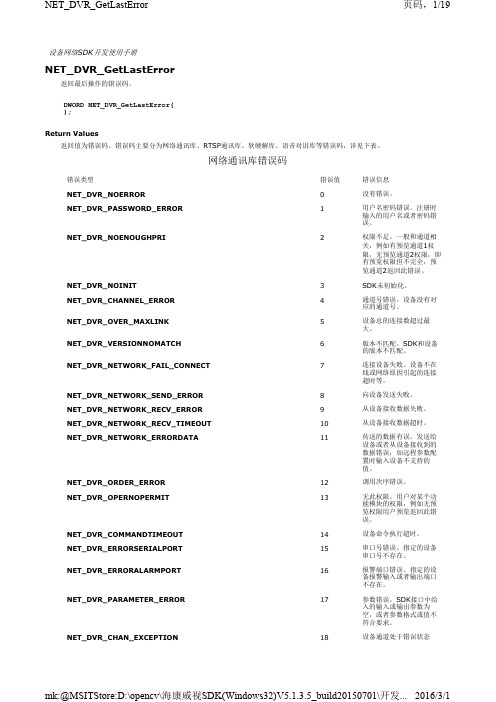
设备网络SDK开发使用手册NET_DVR_GetLastError返回最后操作的错误码。
DWORD NET_DVR_GetLastError();Return Values返回值为错误码。
错误码主要分为网络通讯库、RTSP通讯库、软硬解库、语音对讲库等错误码,详见下表。
网络通讯库错误码错误类型错误值错误信息NET_DVR_NOERROR0没有错误。
NET_DVR_PASSWORD_ERROR1用户名密码错误。
注册时输入的用户名或者密码错误。
NET_DVR_NOENOUGHPRI2权限不足。
一般和通道相关,例如有预览通道1权限,无预览通道2权限,即有预览权限但不完全,预览通道2返回此错误。
NET_DVR_NOINIT3SDK未初始化。
NET_DVR_CHANNEL_ERROR4通道号错误。
设备没有对应的通道号。
NET_DVR_OVER_MAXLINK5设备总的连接数超过最大。
NET_DVR_VERSIONNOMATCH6版本不匹配。
SDK和设备的版本不匹配。
NET_DVR_NETWORK_FAIL_CONNECT7连接设备失败。
设备不在线或网络原因引起的连接超时等。
NET_DVR_NETWORK_SEND_ERROR8向设备发送失败。
NET_DVR_NETWORK_RECV_ERROR9从设备接收数据失败。
NET_DVR_NETWORK_RECV_TIMEOUT10从设备接收数据超时。
NET_DVR_NETWORK_ERRORDATA11传送的数据有误。
发送给设备或者从设备接收到的数据错误,如远程参数配置时输入设备不支持的值。
NET_DVR_ORDER_ERROR12调用次序错误。
NET_DVR_OPERNOPERMIT13无此权限。
用户对某个功能模块的权限,例如无预览权限用户预览返回此错误。
NET_DVR_COMMANDTIMEOUT14设备命令执行超时。
NET_DVR_ERRORSERIALPORT15串口号错误。
926069-ECAD集成-安装PADSVX.1.2
1、安装PADSVX.1.2——使用最新的EFA的破解PADSVX.1.2_mib.exe→右键点击→选择“以管理员身份运行”
提示需要硬件狗,点击“跳过”
提示没有检测到授权文件,点击“跳过”
点击“同意”,同意协议
点击“修改”,进入配置安装环境界面
点击“Product Selection”,选择你需要安装的工具,
一般选择PADS Layout、PADS Router、Design Entry(PADS Logic躲在这里)、Libraries等……(因为是单机运行,Server Service就不用安装了)
点击“Target Path”,设置PADSVX.1.2的安装位置(默认路径)
点击“PADS Projects Path”,设置PADSVX.1.2的项目文件位置(默认),配置完成,点击“Done”
点击“Install”开始安装
安装完毕时会提示注册,选择“at later time”,最后点击“Done”完成安装。
2.破解。
达芬奇DAQNavi SDK软件开发包说明书
FeaturesDAQNavi/SDKSoftware Development Package for Advantech DAQ Products IntroductionDAQNavi is a comprehensive software package, for programmers to develop their application programs using Advantech DAQ boards or devices. This integrated software package includes drivers, SDK, tutorial and utility. With the user-friendly design, even the beginner can quickly get familiar with how to utilize DAQ hardware and write programs through the intuitive "Advantech Navigator" utility environment. Many example codes for different development environment dramatically decrease users’ programming time and effort. You can go to /daqnavi for more information about Advantech DAQNavi.Feature DetailsMultiple Operating System SupportDAQNavi supports many popular operating systems (OS) used in automation applications. For different OSs, API functions will be the same, so users can simply install the driver without modifying their program again when migrating between two different OSs. DAQNavi supports latest Windows system up to Windows 10. (both 32-bit and 64-bit). Besides Windows operating system, Linux is famous for its openness and flexibility. DAQNavi software package also supports Linux OS distributions including Ubuntu, Fedora, Debian and, Redhat. For other distributions, please contact Advantech local branch/support for more information..NET SupportDAQNavi offers a series of .NET Component objects, that you can benefit from platform-unified feature with the latest .NET technology. Users can simply drag and drop the .NET Components within .NET programming environment, such as Microsoft Visual C# and VB .NET. An intuitive window (called "DAQNavi Wizard") will pop-up, and user can perform all configurations by sequence. Programmers also can choose writing code manually with the .NET Component, to have a more flexible object calling. With Advantech CSCL technology, engineers can do the similar programming in Native environment such as Visual C++.LabVIEW SupportLabVIEW is one popular graphical development environment used for measurement and automation. For LabVIEW user, DAQNavi offer two options for programming: Express VI and Polymorphic VI. DAQNavi Express VI for LabVIEW helps user quickly complete his LabVIEW without extra wiring. When the user drags the Express VI on LabVIEW Block Diagram, a pop-up intuitive wizard window will appear and user can perform hardware parameter configurations. After that, the programming is done. So it is similar to the .NET control used in Microsoft Visual Studio environment, suitable for programming beginners. As for the Polymorphic VI, users can use several VIs and wiring to build more complex program.C/C++, Qt, ActiveX and Java SupportDAQNavi also offers C++ Class Library (for VC++ and Borland C++ Builder) and ActiveX (for Visual Basic, Delphi and BCB) for Native programming environment with the same calling interface as .NET Class Library. With DAQNavi Java Class Library, user can develop Java program to across different platforms (including Windows and Linux) by means of Java engine.Device SupportDAQNavi supports all Advantech PCI Express, PCI, PC-104, and PCI-104 cards, as well as all USB DAQ devices.Intuitive UtilityDAQNavi delivers one integrated easy-to-use and powerful utility, called Advantech Navigator. Within the Navigator, engineers can quickly start configuration and function testing for all Advantech DAQ devices, without any programming. Related user manuals are also displayed in the same environment. Besides, to help shorten development time, Advantech offers a series of DAQ applications examples (called "scenarios" in the Advantech Navigator). So programmers can refer to its source code and develop their application based on it, as well as the wiring information. Without a DAQ device at hand, engineers can generate a simulated device and use that device for programming and testing. Except for device testing, Navigator also offers complete documentation to describe how to use DAQNavi SDK to program in various development environments. Moreover, video tutorials for how to create applications in different development environments are available.Supports multiple operating systems including Windows (32-bit and 64-bit), LinuxSupports common-used development environment including Visual C/C++, Borland C Builder, Visual Basic .NET, Visual C#, Delphi, Java, VB, LabVIEW Supports Advantech PCI Express, PCI, PC/104, PCI-104, USB DAQ devices Integrated utility environment (Advantech Navigator) for device functionality testing without programmingAble to generate a simulator device in utility to program and run application without real hardware devicePre-defined scenario application examples with source code to shorten programming learning and development timeExpress VI and Polymorphic VIs for both beginner and advanced programming in LabVIEW environmentComprehensive documentations and tutorials for hardware specifications,wiring, example code and SDK programmingAll product specifications are subject to change without st updated: 20-Mar-2020。
TI最新达芬奇处理器DM6467 — TMDXEVM6467
TI最新达芬奇处理器DM6467 — TMDXEVM6467德州仪器(TI)最新推出了一款能够在多种应用间进行视频转码的新型达芬奇技术数字媒体处理器,这些应用包括媒体网关、多点控制设备、数字媒体适配器、视频安全监控DVR 以及IP 机顶盒等。
新型TM S320DM6467达芬奇处理器是一种基于DSP的片上系统(SoC),特别适合实时多格式高清(HD)视频编解码,并配套了完整的开发工具及数字多媒体软件。
该芯片集成了ARM926EJ-S内核与600MHz C64x+ DSP内核,并采用了高清视频协处理器、转换引擎与目标视频端口接口,在执行高清H.264 HP@ L4(1080p 30fps、1080i 60fps、720p 6 0fps)的同步多格式编码、解码与转码方面,比前代处理器性能提升了十倍。
实时多格式高清转码技术DM6467专为应对商业及消费类电子市场的高清转码挑战而设计的,通过其多内核设计,能够实现较前代数字媒体处理器高十倍的性能。
DM6467 处理器集成了ARM与DSP内核,并采用高清视频/影像协处理器(HD-VICP)、视频数据转换引擎以及目标视频端口接口。
HD-VICP 通过面向HD 1080i H.264 high profile 转码的专用加速器,实现了超过3GHz 的DSP处理能力,同时视频数据转换引擎还能管理包括垂直下调节(downscaling)、色度采样(chroma samp ling) 以及菜单覆盖(menu overlay) 等功能在内的视频处理任务。
不到300MHz的DSP内核可用于管理多格式视频转码,并为其它应用预留了足够的空间。
DM6467 可满足媒体网关与MCU 等需要转码技术的市场要求,但其强大的灵活性与高效性对要求同时进行高清编码与解码的应用来说也非常具有吸引力,如视频语音或视频安全等对于多通道标清编码要求较高的市场。
该器件的连接外设中还包括标准PCI 总线及千兆以太网。
SDK2.2技术说明文档

防区旁路恢复:没有旁路恢复信息(操作24小时防区时直接上旁路信息,再操作防区旁路编码,旁路恢复)
子系统跳转:1234##(第一子系统)1234####(第二子系统)依次累加
进入编程:9876#0
退出编程:L*
枫叶728主机:
布防:474747或4747
3.状态码查询支持主机类型新增了vista120,MTA311,CC408,vista20p,DS7400,DS7240
4.键盘序列帧不支持修改主机编程项内容
5.SDK_DEMO中配置文件config是为vista120主机专用(120主机使用j8口传输数据)
6.CK主机使用键盘序列帧多防区旁路时,只能连续旁路5个防区
5.点击布防按钮,提示信息如下,则表明SDK回控成功
附录三
SDK_DEMO支持接入的各主机使用虚拟键盘的基本操作说明
CK系列:
布防1234#
撤防1234#
防区旁路1234C防区号(1)#
防区旁路恢复1234C防区号(1)#
进入编程012345*0#
退出编程*#
MTA311主机:
布防1234#
撤防1234#
修改帐号:指修改模块ID号
修改类型:指主机的类型
虚拟键盘地址:指主机的键盘地址
虚拟键盘:指模拟各类型主机的键盘
获取模块数量:指查询当前模块在线个数
继电器控制:指模拟联动模块,控制联动模块
状态查询:指查询CK系列及MTA311主机的当前状态
附录一
SDK回控设置步骤说明
1.打开M_51NET设置软件,选择开始搜索,选中需要下载的模块
7.SDK缓存数量为100000条
达芬奇调色软件帮助文件

• 12 GB RAM or higher.
• Two x16 lane PCIe 2.0 slots are required for GPU cards. Some GPU cards require double width slots and some may require auxiliary power connections.
41
Warranty
42
DAVINCI RESOLVE FOR WINDOWS - CERTIFIED CONFIGURATION GUIDE
Understanding DaVinci Resolve for Windows
The world’s highest performing color grading system is now made simple. You can now build your own DaVinci Resolve with this easy to follow guide.
14
Configuring Third Party Control Panels
15
Building a Resolve
16
What to buy
33
Certified Components
34
DaVinci Resolve Control Surface – Dimensions and Weights
• x8 lane PCIe 2.0 slots are preferred for RED Rocket cards or a host bus adapter (HBA) card. However x4 lane PCIe 2.0 slots can be used.
DE2demoSD
DE2板demo的SD卡读取程序注释不知道是不是写对了,欢迎大家批评指正#ifndef __SD_Card_H__#define __SD_Card_H__//-------------------------------------------------------------------------// SD Card Set I/O Direction#define SD_CMD_IN IOWR(SD_CMD_BASE, 1, 0)#define SD_CMD_OUT IOWR(SD_CMD_BASE, 1, 1)#define SD_DAT_IN IOWR(SD_DAT_BASE, 1, 0)#define SD_DAT_OUT IOWR(SD_DAT_BASE, 1, 1)// SD Card Output High/Low#define SD_CMD_LOW IOWR(SD_CMD_BASE, 0, 0)#define SD_CMD_HIGH IOWR(SD_CMD_BASE, 0, 1)#define SD_DAT_LOW IOWR(SD_DAT_BASE, 0, 0)#define SD_DAT_HIGH IOWR(SD_DAT_BASE, 0, 1)#define SD_CLK_LOW IOWR(SD_CLK_BASE, 0, 0)#define SD_CLK_HIGH IOWR(SD_CLK_BASE, 0, 1)// SD Card Input Read#define SD_TEST_CMD IORD(SD_CMD_BASE, 0)#define SD_TEST_DAT IORD(SD_DAT_BASE, 0)//-------------------------------------------------------------------------#define BYTE unsigned char#define UINT16 unsigned int#define UINT32 unsigned long//-------------------------------------------------------------------------void Ncr(void);//Ncr是从CMD到RSP的CLK数目,最小2个周期最大64个周期;void Ncc(void);//Ncc是从CMD到下个CMD的CLK数目,最小8个周期;BYTE response_R(BYTE);//接收从CARD发送过来的Response的函数;BYTE send_cmd(BYTE *);//向CARD发送CMD的函数BYTE SD_read_lba(BYTE *,UINT32,UINT32);//读LBA.BYTE SD_card_init(void);//CARD初始化;//-------------------------------------------------------------------------BYTE read_status;//读操作的状态BYTE response_buffer[20];BYTE RCA[2];//Relative Card Address相对卡地址,用于在多SD卡中标识某卡,从000开始分配。
DAVINCI技术剖析及实战实用开发指南 作者 张亮 第5章.ppt
App[24]中定义了各种Engine的配置,包括Engine的名称 、编码/解码器等。对于应用程序是在本地执行还是在远端 执行,通过配置脚本即可实现。App中通过调用各种API实 现具体算法实例。本章会对这些具体的API进行详细的描述 ,便于读者使用。此外本章针对达芬奇技术中的Generic Trace Support 模块,也进行了讲解,方便读者调试使用。
这个函数的返回值是当前使用的内存总量。如果返回 值为0,则可通过5.2.4节中提到的函数Engine_getLastError() 返回以下两种情况:
● Engine_ERUNTIME:内部运行错误或潜在的 Server错误发生。
● Engine_ENOTAVAIL:内存使用情况无法计算。
18
2. Engine_getCpuLoad
29
表5.9 Engine_ getLastError函数
Engine_Error Engine_ getLastError (Engine_Handle engine)
30
Hale Waihona Puke 5.3 VISA的APIs
Codec Engine的工作是通过完成VISA API的任务来体 现的。VISA API通常分为四部分,create、control、process 和delete。函数中所有的参数结构可详见 /opt/dvsdk_1_40_02_33/ xdais_6_10_01/ packages/ti/xdais/dm 目录下的文件。
Engine_getCpuLoad获得当前时刻的CPU使用信息,其 函数结构和参数如表5.6所示。
19
表5.6 Engine_getCpuLoad函数
Int Engine_getCpuLoad(Engine_Handle engine)
海康威视设备网络SDK编程指南(解码器)
视频解码器用户手册说明书
Video DecoderUser Manual Manual Version:V1.00Thank you for purchasing our product. If there are any questions, or requests, please do not hesitate to contact the dealer.CopyrightCopyright 2016 Zhejiang Uniview Technologies Co., Ltd. All rights reserved. No part of this manual may be copied, reproduced, translated, or distributed in any form or by any means without prior consent in writing from our company.Trademark Acknowledgementand other Uniview's trademarks and logos are the property ofZhejiang Uniview Technologies Co., Ltd. Other trademarks, company names and product names contained in this manual are the property of their respective owners.DisclaimerCAUTION!The default password is used for your first login. To ensure account security, please change the password after your first login. You are recommended to set a strong password (no less than eight characters).●To the maximum extent permitted by applicable law, the productdescribed, with its hardware, software, firmware and documents, isprovided on an "as is" basis.●Best effort has been made to verify the integrity and correctness ofthe contents in this manual, but no statement, information, orrecommendation in this manual shall constitute formal guaranteeof any kind, expressed or implied. We shall not be held responsiblecontents of this manual are subject to change without prior notice.Update will be added to the new version of this manual.●Use of this manual and the product and the subsequent result shallbe entirely on the user's own responsibility. In no event shall we beliable for any special, consequential, incidental, or indirectdamages, including, among others, damages for loss of businessprofits, business interruption, or loss of data or documentation, orproduct malfunction or information leakage caused by cyber attack,hacking or virus in connection with the use of this product.●Video and audio surveillance can be regulated by laws that varyfrom country to country. Check the law in your local region beforeusing this product for surveillance purposes. We shall not be heldresponsible for any consequences resulting from illegal operationsof the device.●The illustrations in this manual are for reference only and may varydepending on the version or model. The screenshots in this manualmay have been customized to meet specific requirements and userpreferences. As a result, some of the examples and functionsfeatured may differ from those displayed on your monitor.●This manual is a guide for multiple product models and so it is notintended for any specific product.●Due to uncertainties such as physical environment, discrepancymay exist between the actual values and reference values providedin this manual. The ultimate right to interpretation resides in ourcompany.Environmental ProtectionThis product has been designed to comply with the requirements onenvironmental protection. For the proper storage, use and disposal ofthis product, national laws and regulations must be observed.Safety and Compliance InformationSafety SymbolsThe symbols in the following table may be found on installation-related equipment. Be aware of the situations indicated and take necessary safety precautions during equipment installation and maintenance.The symbols in the following table may be found in this manual.Carefully follow the instructions indicated by the symbols to avoid hazardous situations and use the product properly.Symbol DescriptionWARNING!Indicates a hazardous situation which, if not avoided, could result in bodily injury or death.CAUTION!Indicates a situation which, if not avoided, could result in damage, data loss or malfunction to product.NOTE!Indicates useful or supplemental information about the use of product.Safety InformationRead through the instructions carefully before starting installation and operation.Installation and maintenance must be performed by qualified●This device is a class A product and may cause radio interference.Take measures if necessary.●While shipping, the device should be packed in its original packing.●Disconnect power before installation and cable connection. Powerdown the device before connecting and disconnecting cables, accessories and peripherals.●Verify installation and cable connection are correct before use.Incorrect installation and connection may cause personal injury and device damage.●Protect the power cable from being stepped on or pressed,particularly at the plug, receptacle, and the part leading out of the device.●Follow the procedure to shut down the device properly. Use anUninterrupted Power Supply (UPS) if possible. Sudden power failures can cause disk damage or device malfunction.●Improper use or replacement of the battery may cause risk ofexplosion. Use the manufacturer recommended battery. Dispose of the used battery according to local regulations or the battery manufacturer's instructions. Never dispose of the battery in fire.●Ensure a proper operating environment, including temperature,humidity, ventilation, power supply, and lightning protection. Make sure the device is always properly grounded. Keep the device from dust, excessive vibration and strong electromagnetic radiation.●Do not use the device near water or expose to rain or moisture.Never spill liquid of any kind on the device. Never let liquid of any kind enter the device.●Never stare at the optical module or optical fiber connector duringoperation.●Take necessary measures to ensure data security and protect thedevice from network attack and hacking (when connected toInternet). Possible risks and consequences are at user's solediscretion.● Contact your dealer if the device does not work properly. Neverattempt to disassemble the device yourself. User shall assume allresponsibility for damage, loss, or injury caused by unauthorizedrepair or maintenance.WARNING!● Never look at the transmit laser while the power is on. Never look directly at the fiber ports and the fiber cable ends when they are powered on.●Use of controls or adjustments to the performance or procedures other than those specified herein may result in hazardous laser emissions.Regulatory ComplianceFCC Part 15This equipment has been tested and found to comply with the limits for digital device, pursuant to part 15 of the FCC Rules. These limits are designed to provide reasonable protection against harmful interference when the equipment is operated in a commercial environment. This equipment generates, uses, and can radiate radio frequency energy and, if not installed and used in accordance with the instruction manual, may cause harmful interference to radio communications. Operation of this equipment in a residential area is likely to cause harmful interference in which case the user will be required to correct the interference at his own expense.This product complies with Part 15 of the FCC Rules. Operation is subject1.This device may not cause harmful interference.2.This device must accept any interference received, includinginterference that may cause undesired operation.LVD/EMC DirectiveThis product complies with the European Low Voltage Directive 2006/95/EC and EMC Directive 2004/108/EC.WEEE Directive–2002/96/ECThe product this manual refers to is covered by the Waste Electrical & Electronic Equipment (WEEE) Directive and must be disposed of in a responsible manner.Contents1 Introduction (1)2 Login (1)3 Common Functions (2)4 Network (3)TCP/IP (3)Telnet (4)SNMP (5)5 Audio and Video (7)Audio (7)Video (8)Media Stream (8)6 Service (9)Image (9)Transparent Channel (11)7 System (12)User (12)Time (12)Management Platform (13)Serial Port (14)8 Maintenance (16)Maintenance (17)Device Status (17)Decoding Status (18)1 IntroductionThis manual describes how to manage the device on a Web browser.The figures in this manual are only for illustration purpose. Theparameters, options and values actually displayed on the Web pages ofyour device may be different from those in this manual.2 LoginBefore you start, check that:The device is operating properly.The computer is connected to the device.The computer is installed with Microsoft Internet Explorer (IE) 7.0 or higher, and no proxy server is being used.NOTE!●The default IP address of your device is 192.168.0.14; the defaultsubnet mask is 255.255.255.0; the default gateway is 192.168.0.1.●Use admin as the username and password for first-time login. Pleasechange the default password under System to ensure accountsecurity.Follow the steps to log in to the device:1.Enter the device's IP address in the address bar and then pressEnter.2.Log in with the correct username and password. The Commonpage is displayed to list the frequently used functions. For details,see Common Functions.3 Common FunctionsThe Common page lists functions that are frequently used to manage the device. The table below describes the meaning of the icons on this page.firmware version, network settings, and management mode.For more details, seethe screen, image resolution and refresh rate, and remainingdecoding capacity of the device. For more details, seeDecoding StatusSet network parameters such as IP address for the device.For more details, seeSet parameters required if the device is to be managed by amanagement platform (central server). For more details, seeManagement PlatformSet vidoe output parameters, including the number ofwindows that appear on the screen, image resolution andrefresh rate. For details, seeSet maintenance parameters. For details, see4 NetworkSet network settings include TCP/IP and Telnet so that the device can communicate with other devices on the network.TCP/IPAssign a static IP address manually, or obtain one using the DHCP server.1.Click Network > TCP/IP.2.Set the parameters. Some are described in the table below.3.Click Save.TelnetEnable Telnet if you want to access the device from a computer with Telnet. The username and password for Telnet are the one you use to access the device on a Web browser. If the password for Web access is changed, the Telnet password changes too. By default the admin username cannot be changed.1.Click Network > Telnet.2.Select the check box to enable Telnet, and then click Save. SNMPEnable Simple Network Management Protocol (SNMPv3) if the device operates in server mode (managed via a central server). Through SNMP the central server synchronizes audio/video channel configurations and some of the scheduled tasks to the device, and the device reports device alarms to the central server.1.Click Network > SNMP.2.Set the parameters. Some are described in the table below.5 Audio and VideoSet video, audio and media stream parameters. The major functionsprovided on the Video&Audio menu are listed in the table below.NOTE!●In standalone mode, all parameters under Video & Audio can beconfigured on the client computer.●In server mode, only Display Mode can be configured on the clientcomputer; other parameters can only be configured on the centralserver.AudioSelect the output channel and adjust the sound volume as needed.1.Click Audio & Video > Audio.2.Set the parameters and then click Save.VideoSelect the output channel and then set the number of windows on the screen, image resolution and refresh rate.1.Click Audio & Video > Video.2.Set the parameters and then click Save.Media StreamSet media stream parameters, including the stream source address and address format, so that the device can receive media streams from the connected cameras.1.Click Audio & Video > Media Stream.2.Set the parameters. Some are described in the table below.6 ServiceSet image parameters and a transparent channel as needed. The major functions provided on the Service menu are listed in the table below.ImageSet the image display ratio, width and color of the divider line on the screen, and crop images as needed.1.Click Service > Image.2.Set the parameters. Some are described in the table below.Transparent ChannelSet the transparent channel to transfer video and audio signals through a serial port.1.Click Service > Transparent Channel.2.Set the parameters. Some are described in the table below.7 SystemSet system parameters, including the user password, system time, system language, management platform, and serial port.UserChange the default password to a strong one (at least 8 digits) after your first login. It is also recommended that you change the password periodically to ensure account security.1.Click System > User.2.Enter the old and new passwords.3.Click Save.TimeSet system time for your device and how the time is updated.1.Click System > Time.2.Set the parameters. Some are described in the table below.NOTE!The device synchronizes time with the central server when operating in server mode.Management PlatformConfigure the management platform only when the device operates inserver mode (managed by a central server).1.Click System > Platform.2.Select Connect to Platform.3.Set the parameters. Some are described in the table below.4.Click Save.Serial PortSet the serial port on the device, including the port type, baud rate, parity check, and flow control method.1.Click System > Serial Port.2.Select the desired port and then set parameters accordingly. Theparameters displayed vary with the serial port selected. Thefigure below shows the parameters displayed when COM 1isselected.The figure below shows the parameters displayed when COM 2is selected.3.Some parameters are described in the table below.NOTE!In server mode, only Duplex can be configured on the Web browser, and all the other parameters can be configured only on the central server. 8 MaintenanceThe major functions provided on the Maintenance menu are listed inthe table below.MaintenanceClick Maintenance> Maintenance and then perform maintenance operations as needed. You can restart the device, restore some factory default settings, import and export configuration files, export logs, and upgrade the device.Device StatusClick Maintenance> Device Status to view basic information of the device, its network settings and operation status. The following shows an example.Decoding StatusClick Maintenance> Decoding Status to view decoding status, including the output channel, number of windows on the screen, image resolution and refresh rate, remaining decoding capacity, and stream source address. The following shows an example.。
- 1、下载文档前请自行甄别文档内容的完整性,平台不提供额外的编辑、内容补充、找答案等附加服务。
- 2、"仅部分预览"的文档,不可在线预览部分如存在完整性等问题,可反馈申请退款(可完整预览的文档不适用该条件!)。
- 3、如文档侵犯您的权益,请联系客服反馈,我们会尽快为您处理(人工客服工作时间:9:00-18:30)。
Application Report SPRAAH0A – April 2007
1 EncodeDecode Demo for the DVEVM/DVSDK 1.2 Niclas Anderberg SDO Applications ABSTRACT The DaVinci Digital Video Evaluation Module (DVEVM) comes with demonstration applications that illustrate the use of its software and hardware components. This document describes the design of the “EncodeDecode” demo application. The EncodeDecode demo uses the Codec Engine as well as video algorithms from Texas Instruments to first encode video data captured using the VPSS front end, and then decode this video data to be displayed on the VPSS back end peripheral of the DM6446.
Contents 1 Overview..........................................................................................................................................2
2 Application Design..........................................................................................................................3 2.1 Main Thread..................................................................................................................4 2.2 Control Thread...............................................................................................................5 2.3 Video Thread.................................................................................................................6 2.3.1 Display Thread..............................................................................................................7 2.3.2 Capture Thread.............................................................................................................8 2.3.3 Video Thread Interaction...............................................................................................9 3 Replacing the Encode and Decode Algorithms with Other Codecs.........................................10 4 More Information...........................................................................................................................12
Figures Figure 1. EncodeDecode Demo Architecture............................................................................2
Figure 2. EncodeDecode Demo Threads...................................................................................3 Figure 3. Main Thread Flow........................................................................................................4 Figure 4. Video Thread Initialization Flow.................................................................................6 Figure 5. Video Thread Interactions...........................................................................................9 SPRAAH0A
2 EncodeDecode Demo for the DVEVM/DVSDK 1.2 1 Overview The encodedecode demo shows how to encode and decode video using algorithms and the Codec Engine from Texas Instruments on the DaVinci DM6446 DVEVM board. The video algorithm used is H.264 and is implemented using the xDM interface (see Section 4 for information reference). The H.264 encoder and decoder algorithms are packaged in a Codec Server (loopbackCombo.x64P) managed by the Codec Engine and executed on the DaVinci DSP core.
Figure 1. EncodeDecode Demo Architecture The DaVinci ARM core runs the demos on the Linux operating system, and all peripherals are controlled through Linux device drivers. The ARM displays a user interface on the OSD (On Screen Display) and takes input from a remote control that allows users to send commands through the EVM board’s IR interface. The DSP core runs the DSP/BIOS real time operating system and performs algorithm processing.
For information on how to run the encodedecode demo including documentation on the command-line parameters, see Section 4 on how to find the encodedecode.txt file. SPRAAH0A
EncodeDecode Demo for the DVEVM/DVSDK 1.2 3 2 Application Design The application consists of four separate POSIX threads (pthreads): the main thread (main.c), which eventually becomes the control thread (ctrl.c), the video thread (video.c), the capture thread, and the display thread (display.c). The video, display, and capture threads are spawned from the main thread before the main thread becomes the control thread. This means that 4 application threads are running in the demo process.
All threads except the original main/control thread are configured as preemptive and priority-based scheduled (SCHED_FIFO). The video, capture, and display threads share the highest priority, while the control thread has the lowest priority. For more on POSIX threads see Section 4.