FT021F测试板 HX1304F HX1364A
JDSU JD786A CellAdvisor RF Analyzer 产品说明书

JD786ACellAdvisor™ RF AnalyzerSpectrum Analyzer: 9 kHz to 8 GHzCable and Antenna Analyzer: 5 MHz to 6 GHzPower Meter: 10 MHz to 8 GHzSpecification* ConditionsThe JD786A specifications apply under these conditions:• The instrument has been turned on for at least 15 minutes• The instrument is operating within a valid calibration period• Data with no tolerance are considered typical values• Cable and antenna measurements apply after calibration to the OSL standard• Typical and nominal values are defined as:–Typical: expected performance of the instrument operating under 20° to 30°Cafter being at this temperature for 15 minutes–Nominal: a general, descriptive term or parameterSpectrum Analyzer (Standard)FrequencyFrequency range 9 kHz to 8 GHzInternal 10 MHz Frequency ReferenceAccuracy ±0.05 ppm + aging (0 to 50°C)Aging±0.5 ppm/yearFrequency SpanRange 0 Hz (zero span)10 Hz to 8 GHzResolution 1 HzResolution Bandwidth (RBW)–3 dB bandwidth 1 Hz to 3 MHz 1-3-10 sequence Accuracy±10% (nominal)Video Bandwidth (VBW)–3 dB bandwidth 1 Hz to 3 MHz 1-3-10 sequence Accuracy±10% (nominal)Single Sideband (SSB) Phase NoiseFc 1 GHz, RBW 10 kHz, VBW 1 kHz, RMS detectorCarrier offset:30 kHz100 kHz1 MHz–100 dBc/Hz (–102 dBc/Hz, typical)–105 dBc/Hz (–112 dBc/Hz, typical)–115 dBc/Hz (–120 dBc/Hz, typical) Measurement RangeDANL to +25 dBmInput attenuator range 0 to 55 dB, 5 dB stepsMaximum Input LevelAverage continuous power +25 dBmDC voltage±50 VDCDisplayed Average Noise Level (DANL)1 Hz RBW, 1 Hz VBW, 50 Ω termination, 0 dB attenuation, RMS detector Preamplifier off:10 MHz to 3 GHz>3 GHz to 5 GHz>5 GHz to 7 GHz>7 GHz to 8 GHz–140 dBm (–145 dBm, typical)–138 dBm (–142 dBm, typical)–135 dBm (–138 dBm, typical)–132 dBm (–135 dBm, typical) Preamplifier on:10 MHz to 3 GHz>3 GHz to 5 GHz>5 GHz to 7 GHz>7 GHz to 8 GHz–160 dBm (–165 dBm, typical)–158 dBm (–162 dBm, typical)–155 dBm (–158 dBm, typical)–152 dBm (–155 dBm, typical)*All specifications are subject to change without notice.Display Range Log scale and units (10 divisions displayed) 1 to 20 dB/division in 1 dB steps dBm, dBV, dBmV, dBµV Linear scale and units (10 divisions displayed)V, mV, mW, WDetectors Normal, positive peak, sample, negative peak, RMS Number of traces 6Trace functionsClear/write, maximum hold, minimum hold, capture, load view on/offTotal Absolute Amplitude AccuracyPreamplifier off, power level >–50 dBm, auto-coupled 1 MHz to 8 GHz ±1.3 dB (±0.5 dB typical) Add ±1.0 dB 20°C to 30°C–10°C to 55°C after60-minute warm up Reference Level Setting range –120 to +100 dBm Setting resolution Log scale Linear scale0.1 dB1% of reference levelMarkers Marker types Normal, delta, delta pair, noise, frequency count marker Number of markers 6Marker functionsPeak, next peak, peak left, peak right, minimum search marker to center/start/stopRF Input VSWR 1 MHz to 8 GHz1.5:1 (typical)Atten >20 dBSecond Harmonic Distortion Mixer level = –25 dBm 50 MHz to 2.6 GHz <–65 dBc (typical) >2.6 GHz to 8 GHz<–70 dBc (typical)Third-Order Inter-Modulation (Third-order Intercept: TOI)200 MHz to 3 GHz +10 dBm (typical) >3 GHz to 8 GHz +12 dBm (typical)SpuriousInherent residual responseInput terminated, 0 dB attenuation, preamplifier off, RBW at 10 kHz –90 dBm (nominal)Exceptions –**************,1.95,2.57264,3.2, and4.5 GHz–*************.8GHzInput-related spurious <–70 dBc (nominal)Dynamic Range2/3 (TOI-DANL) in 1 Hz RBW >104 dB @ 2 GHzSweep Time Range 0.4 ms to 1000 s 24 µs to 200 sSpan = 0 Hz (zero span)Accuracy ±2%Span = 0 Hz (zero span)ModeContinuous, singleGated Sweep Trigger source External, video, and GPS Gate length 1 µs to 100 ms Gate delay 0 to 100 msTriggerTrigger source Free run, video, external Trigger delay Range Resolution0 to 200 s 6 µsMeasurements*Channel powerOccupied bandwidth Spectrum emission mask Adjacent channel power Spurious emissions Field strengthAM/FM audio demodulation Route map* CW signal generator (Option 003) can be set up simultaneously.Cable and Antenna Analyzer (Standard)Frequency Range 5 MHz to 6 GHz Resolution 10 kHz Accuracy ±1 ppmData Points126, 251, 501, 1001, 2001Measurement SpeedMeasurement Accuracy Corrected directivity 40 dB Reflection uncertainty ±(0.3 + |20log (1+10-EP/20)|) (typical)EP = directivity – measured return lossOutput PowerHigh 5 MHz to 5.5 GHz, 0 dBm (typical)5.5 GHz to 6 GHz, –5 dBm (typical) Low 5 MHz to 6 GHz, –30 dBm (typical) Dynamic RangeReflection 60 dBMaximum Input LevelAverage continuous power +25 dBm (nominal) DC voltage ±50 VDC Interference immunityOn channel On frequency +17 dBm @ >1.4 MHz from carrier frequency (nominal)0 dBm within ±10 kHz from the car-rier frequency (nominal)Measurements Reflection (VSWR)VSWR range Return loss range Resolution 1 to 650 to 60 dB 0.01Distance to Fault (DTF)Vertical VSWR range Vertical return loss range Vertical resolution Horizontal range Horizontal resolution 1 to 651 to 60 dB0.010 to (# of data points – 1) x horizontal resolution Maximum = 1500 m (4921 ft)(1.5 x 10⁸) x (VP)/(delta)V P = propagation velocityDelta = stop freq – start freq (Hz)Cable Loss (1-port)Range Resolution 0 to 30 dB 0.01 dB1-port PhaseRange Resolution –180° to +180° 0.01°Smith ChartResolution0.01RF Power Meter (Standard)General ParametersDisplay range –100 to +100 dBmOffset range0 to 60 dBResolution0.01 dB or 0.1xW (x = m, u, p) Internal RF Power SensorFrequency range 10 MHz to 6 GHzSpan 1 kHz to 100 MHz Dynamic range–120 to +25 dBm Maximum power+25 dBmAccuracy Same as spectrum analyzerExternal RF Power SensorsDirectional Power Sensor JD731BFrequency range300 MHz to 3.8 GHzDynamic range0.15 to 150 W (average)4 to 400 W (peak)Connector type Type-N female on both ends Measurement type Forward/reverse average power,forward peak power, VSWR Accuracy±(4% of reading + 0.05 W)1,2 Directional Power SensorFrequency rangeJD733A150 MHz to 3.5 GHzDynamic range0.1 to 50 W (average)0.1 to 50 W (peak) Connector type Type-N female on both ends Measurement type Forward/reverse average power,forward peak power, VSWR Accuracy±(4% of reading + 0.05 W)1,2 Terminating Power Sensor JD732BFrequency range20 MHz to 3.8 GHzDynamic range–30 to +20 dBmConnector type Type-N maleMeasurement type AverageAccuracy±7%1Terminating Power Sensor JD734BFrequency range20 MHz to 3.8 GHzDynamic range–30 to +20 dBmConnector type Type-N maleMeasurement type PeakAccuracy±7%1Terminating Power Sensor JD736BFrequency range20 MHz to 3.8 GHzDynamic range–30 to +20 dBmConnector type Type-N maleMeasurement type Average and PeakAccuracy±7%11. CW condition at 25°C ±10°C.2. Forward power.Optical Power Meter (Option 13)Optical Power MeterDisplay range –100 to +100 dBmOffset range0 to 60 dBResolution 0.01 dB or 0.1 mWExternal Optical Power SensorsOptical Power Sensor Wavelength range MP-60780 to 1650 nmMax permitted input level+10 dBmConnector input Universal 2.5 and 1.25 mm Accuracy±5%Optical Power Sensor Wavelength range MP-80780 to 1650 nmMax permitted input level+23 dBmConnector input Universal 2.5 and 1.25 mm Accuracy±5%2-Port T ransmission Measurements (Option 001) FrequencyFrequency range 5 MHz to 6 GHzFrequency resolution 10 kHzOutput PowerHigh 5 MHz to 5.5 GHz, 0 dBm (typical)5.5 GHz to 6 GHz, –5 dBm (typical) Low 5 MHz to 6 GHz, –30 dBm (typical) Measurement SpeedVector 1.6 ms/point (typical)Scalar 3.4 ms/point (typical) Dynamic RangeVector 5 MHz to 3 GHz, 80 dB>3 GHz to 6 GHz, 75 dB @average 5 @average 5Scalar 5 MHz to 4.5 GHz, >110 dB4.5 GHz to 6 GHz, >105 dB MeasurementsInsertion Loss/GainRange Resolution –120 to 100 dB 0.01 dB2-Port PhaseRange Resolution –180° to +180° 0.01°Bias-Tee (Option 002)VoltageVoltage range +12 to +32 V Voltage resolution 0.1 V Power8 W Max CW Signal Generator (Option 003)FrequencyFrequency range 25 MHz to 6 GHzFrequency reference±1 ppm maximumFrequency resolution10 kHzOutput PowerRange 5 MHz to 5.5 GHz, –60 to 0 dBm>5.5 to 6 GHz, –60 to –5 dBmStep 1 dBAccuracy±1.5 dB (20 to 30 °C)GPS Receiver and Antenna (Option 010)GPS IndicatorLatitude, longitude, altitudeHigh-Frequency AccuracySpectrum, interference, and signal analyzerGPS lock ±25 ppbHold over (for 3 days) ±50 ppb (0 to 50°C)15 minutes aftersatellite locked Connector SMA, femaleInterference Analyzer (Option 011)MeasurementsSpectrum analyzer Sound indicator, AM/FM audio demodulation,interference ID, spectrum recorder Spectrogram Collects up to 72 hours of dataRSSI Collects up to 72 hours of data Interference finderSpectrum replayerChannel Scanner (Option 012)Frequency Range1 MHz to 8 GHzMeasurement Range–110 to +25 dBmMeasurementsChannel scanner 1 to 20 channelsFrequency scanner 1 to 20 frequenciesCustom scanner 1 to 20 channels or frequenciesGeneral InformationInputs and OutputsRF in Spectrum analyzerConnector Impedance Damage level Type-N, female50 Ω (nominal)>+33 dBm, ±50 VDC (nominal), 3 minReflection/RF out Cable and antenna analyzerConnector Impedance Damage level Type-N, female50 Ω (nominal)>+40 dBm, ±50 VDC (nominal), 3 minRF in Cable and antenna analyzerConnector Impedance Maximum level Type-N, female50 Ω (nominal)>+25 dBm, ±50 VDC (nominal)External trigger, GPSConnector Impedance SMA, female 50 Ω (nominal)External refConnector Impedance Input frequency Input range SMA, female50 Ω (nominal)10 MHz, 13 MHz, 15 MHz –5 to +5 dBmUSBUSB host1 USB client2Type A, 1 port Type B, 1 portLAN RJ45, 10/100Base-TGPIO RJ45Audio jack 3.5 mm headphone jackExternal power 5.5 mm barrel connectorSpeaker Built-in speakerDisplayType Resistive touch screenSize8 inch, LED backlight, transflective LCDwith anti-glare coatingResolution800 x 600PowerExternal DC input 12 to 19 VDCPower consumption 37 W 49 W maximum(when charging battery)BatteryType10.8 V, 7800 mA/hr (Lithium ion) Operating time >3 hours (typical)Charge time 2.5 hours (80%), 5 hours (100%) Charging temperature0° to 45°C (32° to 104°F) ≤85% RH Discharging temperature–20° to 55°C (4° to 131°F) ≤85% RH Storage temperature30° to 25°C (32° to 77°F)≤85% RH (non-condensing)Data StorageInternal4Maximum 100 MBExternal5Limited by size of USB flash drive EnvironmentalOperating temperatureAC Power0° to 40°C (32° to 104°F) with no derating Battery0° to 40°C (32° to 104°F) @charging–10° to 55°C (14° to 131°F) @discharging Maximum humidity 85% RH (non-condensing)Shock and vibration MIL-PRF-28800F Class 2Storage temperature6–55° to 71°C (–67° to 160°F)EMCIEC/EN 61326-1:2006 (complies with European EMC)CISPR11:2009 +A1:2010ESDIEC/EN 61000-4-2Size and Weight (standard configuration)Weight (with battery)<4.3 kg (9.5 lb)Size (W x H x D)295 x 195 x 82 mm(11.6 x 7.7 x 3.2 in)Warranty2 yearsCalibration Cycle1 year1. Connects flash drive and power sensor.2. Connects to PC for data transfer.3. 20 to 85% RH, store battery pack in low-humidity environment.Extended exposure to temperature above 45°C could significantly degrade battery performance and life.4. Up to 3800 traces.5. Supports USB 2.0 compatible memory devices.6. With the battery pack removed.Optional Calibration KitsStandard JD786A9 kHz to 8 GHz Spectrum analyzer5 MHz to6 GHz Cable and antenna analyzer 110 MHz to 8 GHz RF power meter (internal mode)OptionsNOTE: Upgrade options for the JD786A use the designation JD786AU before the respective last three-digit option number.JD786A0012-Port Transmission Measurement 2JD786A002 Bias-Tee (requires optionJD786A001)JD786A003CW Signal Generator JD786A010GPS Receiver and Antenna JD786A011Interference Analyzer 3, 4JD786A012Channel Scanner JD786A013Optical Power Meter 5Standard AccessoriesG710550326AC/DC power adapter 6G710550335Cross LAN cable (1.5 m)6GC73050515USB A to B cable (1.8 m)6GC72450518>1 GB USB memory 6G710550325Rechargeable lithium ion battery 6G710550323Automotive cigarette lighter 12 VDC adapter 6G710550316Stylus pen 6JD780A361JD780A Series user’s manual and applicationsoftware — CD1. Requires calibration kit.2. Requires dual-port calibration kit.3. Highly recommend adding GPS receiver JD786A010.4. Highly recommend adding antennas G7*******x and/or G7*******x.5. Requires MP-60 or MP-80.6.Standard accessories can be purchased separately.Optional RF Power SensorsJD731B Directional Power Sensor (peak and average power)Frequency: 300 MHz to 3.8 GHzPower: average 0.15 to 150 W, peak 4 to 400 WJD733A Directional Power Sensor (peak and average power)Frequency: 150 MHz to 3.5 GHzPower: average/peak 0.1 to 50 WJD732B Terminating Power Sensor (average power)Frequency: 20 MHz to 3.8 GHzPower: –30 to +20 dBmJD734B Terminating Power Sensor (peak power)Frequency: 20 MHz to 3.8 GHzPower: –30 to +20 dBmJD736B Terminating Power Sensor (peak and average power) Frequency: 20 MHz to 3.8 GHzPower: –30 to +20 dBmOptional Optical Power SensorsMP-60 Miniature USB 2.0 Optical Power SensorWavelength Range: 780 to 1650 nm1300, 1310, 1490, 1550 nm: –50 to +10 dBm850 nm: –45 to +10 dBmMP-80 Miniature USB 2.0 Optical Power SensorWavelength range: 780 to 1650 nm1300, 1550 nm: –35 to +23 dBm850 nm: –30 to +23 dBm Optional RF AdaptersG710050570 Adapter Type-N(f) to Type-N(f), DC to 6 GHz, 50 ΩG710050571Adapter Type-N(m) to DIN(f), DC to 4 GHz, 50 ΩG710050572Adapter DIN(m) to DIN(m), DC to 4 GHz, 50 ΩG710050573Adapter Type-N(m) to SMA(f), DC to 18 GHz, 50 ΩG710050574Adapter Type-N(m) to BNC(f), DC to 1.5 GHz, 50 ΩG710050576Adapter Type-N(m) to DIN(m), DC to 4 GHz, 50 ΩG710050577Adapter Type-N(f) to DIN(f), DC to 4 GHz, 50 ΩG710050578Adapter Type-N(f) to DIN(m), DC to 4 GHz, 50 ΩG710050579Adapter DIN(f) to DIN(f), DC to 4 GHz, 50 Ω Optional MiscellaneousG710050581Attenuator 40 dB, 100 W, DC to 4 GHz(unidirectional)JD74050341Soft carrying caseJD71050342Hard carrying caseJD74050343Backpack carrying caseG710050585RF directional coupler, 700 MHz to 4 GHz, 30 dB,input/output; Type-N(m) to Type-N(f), tap off;Type-N(f)7G710050586RF Combiner, 700 MHz to 4 GHz, Type-N(f) toType-N(m)7G710550324External battery chargerJD780A362JD780A series user’s manual – printed version 7. Highly recommended for LTE testing.Test & Measurement Regional Sales。
化工测量设备一览表(仪表)(计量台帐)-1
双金属温度计 双金属温度计
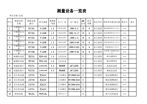
测量设备编 号 PI1513 PI1514 PI1515 PI1516 PI1519 PI1522 PI1524 PI1525 PI1520 TI15110 TI1511
德国科隆
上海自仪三厂
日本横河
单位名称 单位名称:仪表 序号 45 46 47 48 49 50 51 52 53 54 55 56 测量设备名 称 压力变送器 称重仪
双金属温度计 上海自仪三厂 上海自仪三厂
测量设备一览表
测量设备编 号 PDT212 WT201-202 TI201-203 TI211 TI213 PG200-205 PG101-103 PI1-0 PI1-1-3 PI1-4
ALTOFLUXIFM ALTOFLUXIFM
准确度 /等级 1.5 1.5 1.5 1.5 1.5 1.5 1.5 1.5 0.5 0.5
生产厂家
上海自仪四厂 上海自仪四厂 上海自仪四厂 上海自仪四厂 上海自仪四厂 上海自仪四厂
出厂编号 1998/8/2 1998/12/17 1999/1/8 1998-3-59 1999-3-202 1999-3-55
上海自仪三厂 上海自仪三厂
出厂编号
ABC 检定 分类 周期 C C C C C C C C C C C B B 6 6 6 6
检定单位 使用单位配备位置 使用人 外管蒸汽温度 减压后蒸汽温度 外管蒸汽温度 减压后蒸汽压力
出氢气水封后压力 出水环压缩机后压力
备注
*** *** *** *** *** *** *** *** *** *** *** *** *** *** ***
Yokogawa CA150 垂直手持校准仪说明书

Vertical Handheld Calibrator Easy-to-hold vertical body is designed to make it intuitively easy to operate, as individual functions are accessed directly by pressing assigned keys. The main body case (sold separately) is designed to make it easy to hold the CA150 in one hand.Simultaneous Source and Measurement for Process Devices In conventional calibration applications, multiple devices such as a standard generator, dial resistor and multimeter were required. Now with a single CA150 unit, it is possible to perform operation check at regular inspection and maintenance of thermocouples, RTDs and instruments, as well as maintenance and equipment diagnosis of process devices such as transmitters, thermostats and signal converters.Loop Power Supply Function It is possible to measure generated current signals while supplying loop power 24 Vdc from a two-wire type transmitter (up to 22 mA DC).Highly Accurate and Multi-Functional Source and Measurement High Accuracy: 0.02% for the source unit and 0.02% for the measurement unit Source and Measurement Functions: DCV voltage, DC mA, ohm, Frequency and temperature (thermocouple, RTD) and 24 Vdc power supply function for transmitters Memory Functions:Setting Memory This function saves/loads setting conditions. Up to 21 data items can be stored. Settings for (source/ measurement) functions, ranges, generated values/measured values as well as setting mode conditions can be stored.Data Memory This function saves source and measure values displayed. Up to 100 data items can be stored.Storage date/time, (source/ measurement) functions, ranges and generated values/measured values can be stored. Stored data can be checked on the display of the main unit as well as via communication.Multi-Functional Handheld CalibratorU H ighly Accurate Within0.02% of the DC Voltage Range for Source and MeasureU S ource and Measurementcan be Performed SimultaneouslyU V ertical Body with LargeScreen Display U L oop Power SupplyU S ink FunctionU 3 Sweep FunctionOutputs (Step Sweep, Linear Sweep, ProgramSweep)CA150CA150 shown smallerthan actual size.Specifications (Common to Source and Measurement)Communication Functions: Serial interface RS232 D-Sub 9-pin connector Memory Functions: Data can be stored and loaded in setting memory (setting data) and data memory (source/measurement).Specifications (Common to Source Specifications)Power Supply: 6 “AA” size alkaline batteries (included), AC adaptor (sold separately) or dedicated NiMH battery (sold separately)AC Adaptor: 100 to 240 Vac, 50/60 Hz, 1.4 A Output: 12 Vdc, 3 A Battery Life Conditions: Simultaneous source/measurement output of 5 Vdc/10 k Ω or more Vdc A pprox 8 Hours: When 6 batteries are used Approx 10 Hours: When NiMH batteries are used Auto Power-Off: Approx 10 minutes; it can be canceled by setting Insulation Resistance (Between Input Terminal and Output Terminal): 500 Vdc, 50 M Ω or more Withstand Voltage (Between Measurement Terminal andGeneration Terminal): 350 Vac,1 minuteProgram Sweep FunctionOperating Temperature/Humidity Range: 0 to 40°C (32 to 104°F), 20 to 80%RH (no condensation)Storage Temperature Range:-20 to 60°C (-4 to 140°F), 90%RH or less (no condensation)External Dimensions: Approx 251 H x 124 L x 70 W mm (10 x 5 x 3")Weight: Approx 1000 g (oz)Accessories: One set of leadcables for generation, 1 set of lead cables for measurement, carrying case, terminal adaptor, and 1 (spare) fuse for measurement.Conforming Standards:Safety: EN61010-1EMC: EN 61326 Class B;EN 55011 Class B Group1EN 61000-3-2; EN 61000-3-3,EN 61326CA150-STRAP-CASE, strap and accessory CA150-NIMH-BAT, shown smaller than CA150-ACC-CASE, accessory storage case with lead cables, RJ sensor, and more can shown smaller than actual size.O A c Lead cable for source (one set includes 1 red and 2 black cables) Lead cable for measurement All shown smaller* Depending on the internal settings, either ITS-90 or IPTS-68 can be selected.Temperature Coefficient: Accuracy above x (1/10)/°C. The temperature coefficient is added in the ranges from 0 to 18°C and from 28 to 40°C.100 Hz1000 Hz10 kHz50 kHz Specifications(Common to Source Unit) Response Time: Approx 300 m only ranges 1V, 10V, 500Ω (excitation current 1mA) and RTD (excitation current 1mA) response time approx 5 ms (the time from the point where the output starts to change to the point when it gets within the accuracy range) Voltage Limiter: Approx 32 V Current Limiter: Approx 25 mA Output Polarity Switching:Enable division output (n/m) functionoutput = setting value x (n/m). Steps canbe set in the ranges of n = 0 to 19 andm = 1 to 19 condition: n/mStep Sweep Function: Automaticsweep of n values when the division(n/m) function is selected (it can beselected from the following options:5 seconds, 10 seconds and step)Linear Sweep Function/Linear OutputFunction: The sweep time can beselected from the following options:16 seconds and 32 secondsProgram Sweep Function: Outputssource values saved by the datamemory function in the order the valuesare stored in memory (maximum stepsetting: 100 data) (output setting can beselected from the following options:5 seconds, 10 seconds and step)100 Hz1000 HzCPHSpecifications (Common to Measurement Unit) Maximum Measurement Unit Input Voltage Terminal: 42 Vdc Current Terminal: 120 mACurrent Terminal Input Protection Fuse: 125 mA/250 VMeasurement Display Refresh Rate: Approx once per secondSpecifications(Loop Power Supply)Single 24 Vdc power supply (measurement terminal used) Maximum Load: 22 mA DC or lessmA DC Signals: Measured while power is being supplied with the loop check function terminal adaptor.Ordering Examples: CA150-NIST, calibrator with 3-point calibration.CA150, handheld calibrator and CA150-RJ-SENS, reference junction sensor.。
广东省产品质量监督检验中心顺德分中心专用检测仪器设备采购(SD08103)

广东省产品质量监督检验中心顺德分中心专用检测仪器设备采购(SD08103)采购内容及技术要求2.3.1 采购清单2.3.2 A标段采购清单及技术要求2.3.3 B标段采购清单及技术要求2.3.4 其他注意事项1.投标人所投设备的所有配置必须为原厂原装配置。
中标人所投设备如在实际供货时缺货, 必须按原报价提供同品牌、相同或更高配置的设备, 否则视为拒绝履行合同义务处理。
2.中标人应负责在项目验收时将全部有关产品说明书、原厂家安装手册等文档汇集成册交付采购人。
合同主要条款1.交货期: 自合同签订生效之日起30天内, 所有设备安装调试完毕、交付使用并验收合格。
2、付款方式:1)合同签订生效后的15个工作日内支付合同总额的30%;2)所有设备安装调试完毕、交付使用并验收合格后的15个工作日内支付合同总额的65%;3)无违反合同约定的, 在免费保修期满后15个工作日内支付合同总额的5%;3.售后服务:1)免费保修期: 所有设备不少于1年, 在项目验收合格后开始计算;2)响应时间:电话即时响应, 如电话响应无法解决的, 8小时内到达现场。
3)修复时间要求:24小时内修复, 如在24小时内无法解决, 则须采取应急措施或提供冗余服务, 以确保设备正常运行。
4、培训:1)中标人必须提供优质的设备使用培训。
2)培训地点: 使用单位内培训, 中标人负责必要的培训资料、文件和设施。
3)培训基本内容:确保用户能够对设备有足够的了解和熟悉, 能够独立进行设备的操作和保养。
以上合同主要条款为基本要求, 投标人参加投标, 则视为接受上述要求。
投标人可在此基础上作出优惠承诺, 以提高其投标的竞争力。
FT021F HX1304F HX1364C HC2018 HC2018A
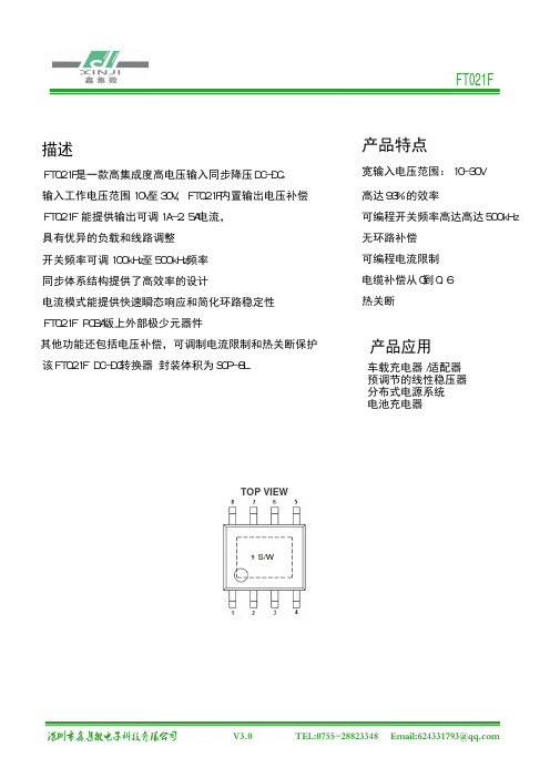
FT021F是一款高集成度高电压输入同步降压DC-DC。
该FT021F DC-DC转换器 封装体积为SOP-8LFT021F PCBA版上外部极少元器件FT021F 能提供输出可调1A-2.5A电流,输入工作电压范围10V至30V,FT021F内置输出电压补偿宽输入电压范围:10-30V描述具有优异的负载和线路调整开关频率可调100kHz至500kHz频率同步体系结构提供了高效率的设计电流模式能提供快速瞬态响应和简化环路稳定性其他功能还包括电压补偿,可调制电流限制和热关断保护高达93%的效率可编程开关频率高达高达500kHz无环路补偿可编程电流限制电缆补偿从0到0.6热关断产品特点车载充电器/适配器预调节的线性稳压器分布式电源系统电池充电器产品应用TOP VIEWS/W* The output voltage is set by R2 and R3: V OUT = 1.21V • [1 + (R2/R3)].P i n A s s i g n m e n t a n d D e s c r i p t i o nA b s o l u t e M a x i m u m R a t i n g s(N o t e1)Input Supply Voltage ....................................................................................................-0.3V ~ 35V FB, ILIM, RT Voltages.................................................................................................... -0.3V ~ 6V SW Voltage ........................................................................................................-0.3V ~(VIN + 1V) Operating Temperature Range (Note 2).........................................................-40℃~ +85℃ Storage Temperature Range.................................................................................. -65℃~ +150℃ Junction Temperature Range.. (150)Lead Temperature (Soldering, 10 sec.) (265)PIN NAME DESCRIPTION1 FB Feedback2 RT FrequencySetting3 ILIM CurrentLimit4 VIN InputSupplyVoltage5, 6 SW Switch Node7, 8 GND Ground该FT021F是保证符合性能规格为0度-70度,在-40至+85度工作温度范围内放心注1:超出所列的绝对最大额定值强调可能会造成永久性损坏设备。
带有积分边值条件的奇异分数阶微分方程正解的存在性

第28卷第5期海南热带海洋学院学报Vol.28No.5 2021年10月Journal of Hainan Tropical Ocean University Oct.2021带有积分边值条件的奇异分数阶微分方程正解的存在性廖秀(桂林信息科技学院数学教研部,广西桂林541004)摘要:利用序列化与正则化的技巧,结合锥压缩-锥拉伸不动点定理证明了一类带有积分边值条件的奇异分数阶微分方程边值问题正解的存在性。
分数阶积分边值问题已有很多实际应用,例如建立耦合的电路模型、AIDS模型等。
关键词:积分边值条件;奇异分数阶微分方程;边值问题;锥压缩-锥拉伸不动点定理;正解中图分类号:0175.1文献标识码:A文章编号:2096-3122(2021)05-0056-10DOI:10.13307/j.issn.2096-3122.2021.05.080引言随着微分方程的发展,分数阶微分方程已广泛应用于控制系统、流变学、粘弹性力学等诸多领域目前,关于分数阶微分方程的研究已经取得了许多成果。
但是,近年来学者们对带有积分边值条件的奇异微分方程正解存在性的研究还是比较少的。
奇异分数阶微分方程有着实际的应用价值,该类微分方程是如今学者们研究的热点。
因此,本文的研究有着重要的意义。
Zhang X等A1101™8运用不动点指数定理证明了如下边值问题多个正解的存在性:.7>o+u(j)+u(«))=0(ie(0,1)),u(0)=14,(0)=u"(0),u(1)=A J I4(s)ds。
白占兵[皿运用序列化和正则化技巧证明了如下奇异分数阶Dirichlet边值问题正解的存在性与解序列:r^+u(i)+/(t,u(t),%“(t))=0(ie[0,l]),lw(0)=u(l)=0oStank S[11]1379运用锥不动点定理讨论下面边值问题解的存在性:盛“⑴+/(t,“(t),瑶+临))=0(北[0,1]),,u(0)=u z(0)=u(1)=0o受以上文献的启发,本文运用序列化和正则化等技巧研究边值问题必+弘(力),DJ+u(z))(f G[0,1]),誑(1)u r(0)=I^~a u(t)=0,limZ)Q~1u(f)=Aj u(s)ds,得到其至少存在一个正解与解序列,其中訂是a阶的Ricmann-Liouville分数阶导数,2<a^3,u>0,入>0,0<”<1,且人和"同时满足[誓-『(a)]>0#是正函数且/在[0,1]x(0,+«)xR±满足Caratheodory条件/(£,"(£),坯+"(/))在t=0处奇异。
- 1、下载文档前请自行甄别文档内容的完整性,平台不提供额外的编辑、内容补充、找答案等附加服务。
- 2、"仅部分预览"的文档,不可在线预览部分如存在完整性等问题,可反馈申请退款(可完整预览的文档不适用该条件!)。
- 3、如文档侵犯您的权益,请联系客服反馈,我们会尽快为您处理(人工客服工作时间:9:00-18:30)。
FUNCTION DESCRIPTION
Feedback Frequency Setting
Current Limit Input Supply Voltage
Switch Node Ground
位置 U1 CIN RT RCS R1 R2 COUT L
型号/参数 FT021F 35V/47µF
150K
DEMO 实物图
VIN=24V Vout=5V;Iout=0A
VIN(V) 23.98 23.98 23.97 23.97 23.97 23.97 23.97 23.96 23.96 23.96 23.95 23.95 23.95 23.95 23.94 23.94 23.94 23.93 23.93 23.93
IOUT(A) 0.5 0.6 0.7 0.8 0.9 1.0 1.1 1.2 1.3 1.4 1.5 1.6 1.7 1.8 1.9 2.0 2.1 2.2 2.3 2.4
EFF(%) 93.45 95.46 90.89 92.89 94.24 91.24 92.52 93.86 91.88 93.12 91.62 92.81 91.39 92.51 91.53 92.61 91.58 90.89 91.74 92.55
应用信息 输出电压计算公式:
输出电流计算公式: 振荡器频率计算公式: 线补计算公式:
VOUT 1.21 1 Rcs(kΩ)=24*IMAX(A).
RT kΩ 22000/f kHz △VOUT(V)=R3(kΩ)*IOUT(A)/20Байду номын сангаас0
FT021F
产品概述 FT021F是应用于 DC 10‐32V 输入,输出电压 5V,输出电流 2.4A 的车充演示板,最高转换效率可高达 97%。 FT021F 是同步整流降压型 DC‐DC 转换芯片(不需要使用续流二极管),可调开关频率 100KHz‐500KHz,可减小外
部元器件尺寸,方便 EMC 设计。芯片具有出色的线性调整率与负载调整率,输出电压支持可调节。芯片内部集成 过流保护、过温保护、输出短路保护、恒压、恒流、线性补偿等可靠性模块。
FT021F为标准 SOP‐8 小体积封装,集成度高,外围器件少,应用灵活。
DEMO 原理图
47UH
管脚介绍
PIN NO.
1 2 3 4 5/6 7/8
物料清单 序号 1 2 3 4 5 6 7 8 9
NAME
FB RT CS VIN SW GND
用量 1 1 1 1 1 1 1 1
FT021F
150K
68K 100K 31.6K 10V/100µF 47UH
厂商
备注
FT021F
性能数据
VIN=12V
VIN(V) 11.99 11.99 11.98 11.98 11.98 11.97 11.97 11.96 11.96 11.95 11.95 11.94 11.94 11.93 11.93 11.92 11.92 11.91 11.90 11.90
IIN(A) 0.22 0.26 0.30 0.35 0.40 0.44 0.49 0.53 0.58 0.63 0.67 0.72 0.77 0.82 0.87 0.92 0.97 1.03 1.08 1.13
Vout=4.98V;Iout=0A
VOUT(V) 4.95 4.96 4.97 4.98 5.00 5.01 5.04 5.07 5.08 5.10 5.12 5.13 5.14 5.16 5.17 5.18 5.19 5.20 5.21 5.18
IIN(A) 0.11 0.13 0.16 0.18 0.20 0.23 0.25 0.27 0.30 0.32 0.35 0.37 0.40 0.42 0.45 0.47 0.50 0.53 0.55 0.57
VOUT(V) 4.93 4.96 4.98 5.01 5.02 5.03 5.04 5.06 5.08 5.10 5.12 5.14 5.15 5.17 5.19 5.21 5.22 5.24 5.25 5.26
IOUT(A) 0.5 0.6 0.7 0.8 0.9 1.0 1.1 1.2 1.3 1.4 1.5 1.6 1.7 1.8 1.9 2.0 2.1 2.2 2.3 2.4
EFF(%) 93.83 95.46 96.80 95.02 93.91 95.12 94.52 95.98 95.20 94.84 95.92 95.48 95.04 94.94 94.64 94.47 94.26 93.26 93.24 92.45