德国Rohm罗姆MANDRELS膨胀芯轴
丹福斯PVE27 -E2-21-C -20螺絡油密闭型推進器零件手冊说明书

M-2241-SHeavy Duty Piston PumpPVE27*-E2-21-C**-20Parts ManualVickers by Danfoss ®PistonPumpsAX441463039773en-000101214688Torque (36.8-40.5(Refer to back page thru-drive valve 227401Torque 15-16N.m (11-12lb.ft.)Valve (See table)404751186580(40-40.3 396098Cylinder 214684Torque (36.8-40.5Guide Block 1489Nut582544Adj. 676561 627375 170160 631529 627374 676578 298126req’d)Torque 31-37lb.ft.)627373 154128 627391Torque 18-20(13-15lb.ft.)1489NutAdj.ScrewPlugSpring SeatO-Ring SpringGuideBody(3req’d)(Press.Limiter)(3req’d)(3req’d)Torqueft.)676584‘C’Pressure compensator S/A preset at 250bar.NoteParts are shown for left hand shaft rotation.The position of control and bias pistons are reversed for right hand rotation.(Assemble using Loctite 270.164881Screw (8req’d)Torque 15-17N.m(11-12lb.ft.)676590Housing 597022Gasket 366865Bearing S/A597033Key 627593Yoke S/A392059Pin584515Swash Plate 584512Shoe Cage632587Spacer926257Piston Kit (Includes 9Piston and Shoe S/A)634470Bias Piston 634499Spring 584485BiasPiston Rod Torque 75-83N.m (55-61ft.lb.)154130O-Ring584511Control Piston584510Control Stem Torque 75-83N.m (55-61lb.ft.)154130O-Ring 227376Screw (2req’d)Nameplate926259Pintle Shim Kit (Refer to Pintle Brg.preload in overhaulmanual)409857Cover (2req’d)589953O-Ring(2req’d)597032Spacer(2req’d)103824Retaining Ring627484Shaft Seal (Spring faces inward) Included in 920267Seal KitIncluded in 938102rotating group Included in 926450Bias Piston Kit Included in 926449Control Piston KitIndividual parts not available for sale.Order complete subassembly.PVE27*-E2-21-C**-20680608ShaftValveBlock680786680630680785680631Valve Plate Shaft Rotation CCW Left CW Right676580‘CVP’Load Sensing Pressure limiter compensator S/A.Shipped preset atapproximately:Load sensing differential pressure 20bar.Pressure limiter 250bar.353187Bearing S/A (2req’d)For satisfactory service life of these components,use full flow filtration to provide fluid which meets ISO cleanliness code 20/18/15or cleaner.Danfoss Power Solutions is a global manufacturer and supplier of high-quality hydraulic and electric components. We specialize in providing state-of-the-art technology and solutions that excel in the harsh operating conditions of the mobile off-highway market as well as the marine sector. Building on our extensive applications expertise, we work closely with you to ensure exceptional performance for a broad range of applications. We help you and other customers around the world speed up system development, reduce costs and bring vehicles and vessels to market faster.Danfoss Power Solutions – your strongest partner in mobile hydraulics and mobile electrification.Go to for further product information.We offer you expert worldwide support for ensuring the best possible solutions foroutstanding performance. And with an extensive network of Global Service Partners, we also provide you with comprehensive global service for all of our components.Local address:DanfossPower Solutions GmbH & Co. OHG Krokamp 35D-24539 Neumünster, Germany Phone: +49 4321 871 0DanfossPower Solutions ApS Nordborgvej 81DK-6430 Nordborg, Denmark Phone: +45 7488 2222DanfossPower Solutions (US) Company 2800 East 13th Street Ames, IA 50010, USA Phone: +1 515 239 6000DanfossPower Solutions Trading (Shanghai) Co., Ltd.Building #22, No. 1000 Jin Hai Rd Jin Qiao, Pudong New District Shanghai, China 201206Phone: +86 21 2080 6201Danfoss can accept no responsibility for possible errors in catalogues, brochures and other printed material. Danfoss reserves the right to alter its products without notice. This also applies to products already on order provided that such alterations can be made without subsequent changes being necessary in specifications already agreed.All trademarks in this material are property of the respective companies. Danfoss and the Danfoss logotype are trademarks of Danfoss A/S. All rights reserved.Products we offer:•Cartridge valves •DCV directional control valves•Electric converters •Electric machines •Electric motors •Gear motors •Gear pumps •Hydraulic integrated circuits (HICs)•Hydrostatic motors •Hydrostatic pumps •Orbital motors •PLUS+1® controllers •PLUS+1® displays •PLUS+1® joysticks and pedals•PLUS+1® operator interfaces•PLUS+1® sensors •PLUS+1® software •PLUS+1® software services,support and training •Position controls and sensors•PVG proportional valves •Steering components and systems •TelematicsHydro-GearDaikin-Sauer-Danfoss。
施瓦格洛克 微调阀-S,M,L,31系列产品手册说明书

S, M, L, and 31 Series■Straight-pattern flow coefficients (C v) from 0.004 to 0.16■ Low- and high-pressure service■Repeatable vernier handles available■Brass and 316 stainless steel materials2 Needle and Metering ValvesT U B E F I T T I N G SP I P E , W E L D , V C R , V C O F I T T I N G SS T A N D A R D T U B I N GM O D U L A R S Y S T E M DH O S E / F L E X I B L E T U B I N GB E L L O W S , D I A P H R A G M V A L V E SB A L L & P L U G V A L V E S31C H E C K & R E L I E F V A L V E SR E G U L A T O R S & F I L T E R S I N S T R U M E N T M A N I F O L D S Y S T E M SM E A S U R E M E N T D E V I C E SR E F E R E N C E SM E D I U M - H I G H - P R E S S U R ELock screw “locks in” flowsettings (knurled andslotted handles)Guide O-ring enhances stemalignment (S series only)Tapered stem tip accurately controls gas and liquid flow ratesStem threads are isolated from system fluidHandle stop helps prevent damage to stem and orifice Stem O-ring contains system fluid➀ D ownstream pressure 500 psig (34.4 bar) max when valve requiresadjustment at pressure due to strength limitations of the fine-pitch threads and high operating torque.➁ S tainless steel L series valves are not recommended for shutoff in vacuum or gas service, or for repetitive shutoff in liquid service.S series valve shown.High-Pressure Valves (31 Series)■ Flow coefficient of 0.04; orifice of 0.062 in. (1.6 mm) ■ 316 SS bar stock body ■ Straight and angle patterns ■ Metal-to-metal shutoff ■ 2° stem taper (included angle)■ P anel mounting ■ Round phenolic handle■ Swagelok tube fitting and female NPT end connectionsPressure-Temperature RatingsRatings based on optional Grafoil ® packing.Ratings limited to 450°F (232°C) at 3435 psig (236 bar) with standard PTFE packing.Packing nut permits simpleexternal adjustment Packingfully contained by 316 SS glands to prevent extrusion 440C SSregulating stemhardened for enhanced service lifeaccurately controls gas and liquid flow ratesMetal-to-metal shutoff31 SeriesMetering Valves—S, M, L, and 31 Series 3Materials of ConstructionLow-Pressure Valves (S, M, and L Series)234568791a 1b2234488759913456891027High-Pressure Valves (31 Series)TestingEvery Swagelok S, M, and L series metering valve is factory tested with nitrogen at 1000 psig (69 bar). Shell testing is performed to a requirement of no detectable leakage with a liquid leak detector.Every Swagelok L series metering valve is tested for bubble-tight seat shutoff at 100 psig (6.8 bar) differential pressure.Every Swagelok 31 series needle valve is factory tested with nitrogen at 1000 psig (69 bar). Seats have a maximum allowable leak rate of 0.1 std cm 3/min.S Series M SeriesL SeriesWetted components listed in italics.➀ Anaerobic-type adhesive.➁ Straight and double-pattern M series valves.➂ A ngle and cross-pattern M series valves do not contain a body seal.1a Cleaning and PackagingSwagelok metering valves with VCR end connections areprocessed in accordance with Swagelok Special Cleaning and Packaging (SC-11) catalog , MS-06-63, to ensure compliance with product cleanliness requirements stated in ASTM G93 Level C .Swagelok metering valves with other end connections are processed in accordance with Swagelok Standard Cleaning and Packaging (SC-10) catalog, MS-06-62, special cleaning and packaging are available as an option.4 Needle and Metering ValvesM series valve shown.S series—0.16 in. (4.1 mm) maximum panel thickness.M and L series—0.13 in. (3.3 mm) maximum panel thickness.31 SeriesFor angle-pattern 31 series valves, add -A to the ordering number.Example: SS-31RS4-AMaximum Flow—0.16 C vMaximum Flow—0.04 C vStraight PatternMetering Valves—S, M, L, and 31 Series 5DimensionsDimensions, in inches (millimeters), arefor reference only and are subject to change.Angle PatternAngle Pattern6 Needle and Metering ValvesTUBEFITTINGSPIPE,WELD,VCR,VCOFITTINGSSTANDARDTUBINGMODULARSYSTEMDHOSE/FLEXIBLETUBINGBELLOWS,DIAPHRAGMVALVESBALL&PLUGVALVES31CHECK&RELIEFVALVESREGULATORS&FILTERSINSTRUMENTMANIFOLDSYSTEMSMEASUREMENTDEVICESREFERENCESMEDIUM-HIGH-PRESSUREDouble PatternS and M Series■ Inlet valve handle can be set andlocked at desired maximum flow.■ Outlet valve handle can be used forfine flow control up to the presetmaximum of the inlet valve.S series valve shown.Cross PatternS and M Series■ Fluid flows between side portsaround stem in any stem position.■ Flow through branch port can bemetered in both directions.Ordering Information and DimensionsSelect an ordering number. For brass valves, replace SS with B.Example: B-SS2-XDimensions are for reference only and are subject to change.M series valve shown.Options and AccessoriesMetering Valves—S, M, L, and 31 Series 7Colored Handles31 SeriesBlack phenolic handles are standard. To order colored phenolic handles, add a handle color designator to the ordering number.Example: SS-31RS4-BL Handle KitsHandle kits contain handle, brass insert, and instructions.To order a black phenolic handle, use kit ordering number PH-5K -14K-BK.For colored phenolic handles, replace -BK in the kit ordering number with a handle color designator.Example: PH-5K-14K -BLAdjustable-Torque HandleVernier HandleS, M, and L Series■ Enhances control for setting flows.■ Features PTFE packing and two top-mounted torque adjustment screws.■ Is available in stainless steel materialon stainless steel valves and in chrome-plated brass on brass valves, as standard.To order, add -OH to the ordering number.Example: SS-SS1-OHAdjustable-Torque Handle Kits Kits contain all parts necessary to add an adjustable-torque handle to an existing valve.Slotted HandleS and M Series■ Helps ensure repeatable flow adjustments.■ Provides readings accurate to1/25 turn.To order, add -VH to an S series ordering number or -MH to an M or L series ordering number.Examples:S S-SS1-VHSS-2MG -MH Vernier Handle KitsKits contain all parts necessary to add a vernier handle to an existing valve.■ Allows flow setting adjustment with ascrewdriver.■ Is for use in installations wherehandle is not easily accessible.■ Is available in stainless steel materialon stainless steel valves and in chrome-plated brass on brass valves, as standard.■ Allows valve to be panel mountedwithout removing handle.To order, add -SL to the ordering number.Example: SS-SS1-SLDimensions, in inches (millimeters), are for reference only and are subject to change.1.82 (46.2)open(21.0)A openM series valve shown.Slotted Handle KitsKits contain all parts necessary to add a slotted handle to an existing valve.1.42 (36.1)open(12.2)Options and Accessories8 Needle and Metering ValvesT U B E F I T T I N G SP I P E , W E L D , V C R , V C O F I T T I N G SS T A N D A R D T U B I N GM O D U L A R S Y S T E M DH O S E / F L E X I B L E T U B I N GB E L L O W S , D I A P H R A G M V A L V E SB A L L & P L U G V A L V E S31C H E C K & R E L I E F V A L V E SR E G U L A T O R S & F I L T E R SI N S T R U M E N T M A N I F O L D S Y S T E M SM E A S U R E M E N T D E V I C E S R E F E R E N C E SM E D I U M - H I G H - P R E S S U R E High-Temperature Stem Packing Material31 SeriesGrafoil packing extends the temperature rating to 850°F (454°C) and requires fluorinated tungsten disulfide-based lubricant. To order, add -G to the ordering number.Example: SS-31RS4-G Stem Packing KitsPTFE and Grafoil packing kits are available. Kits include packing, lubricant, and instructions. Select a kit ordering number.Special Cleaning and Packaging (SC-11)All SeriesSwagelok metering valves with VCR end connections are processed in accordance with Swagelok Special Cleaning and Packaging (SC-11) catalog , MS-06-63, to ensurecompliance with product cleanliness requirements stated in ASTM G93 Level C .To order special cleaning and packaging for metering valves with other end connections, add -SC11 to the valve ordering number.Example: SS-SS1-SC11Oxygen Service HazardsFor more information about hazards and risks of oxygen-enriched systems, refer to Swagelok Oxygen System Safety technical report, MS-06-13.MS-01-142, RevM, November 2021Options and Accessories• A packing adjustment may be required periodicallyto increase service life and to prevent leakage.• To increase service life, ensure proper valveperformance, and prevent leakage, apply only as much torque as is required to achieve positive shutoff in L and 31 series valves that are rated for shutoff service.IntroductionSince 1947, Swagelok has designed, developed, and manufactured high-quality, general-purpose and specialty fluid system products to meet the evolving needs of global industries. Our focus is on understanding our customers’ needs, finding timely solutions, and adding value with our products and services.We are pleased to provide this global edition of the book-bound Swagelok Product Catalog, which compiles more than 100 separate product catalogs, technical bulletins, and reference documents into one convenient, easy-to-use volume. Each product catalog is up to date at the time of printing, with its revision number shown on the last page of the individual catalog. Subsequent revisions will supersede the printed version and will be posted on the Swagelok website and in the Swagelok electronic Desktop Technical Reference (eDTR) tool.For more information, visit your Swagelok website or contact your authorized Swagelok sales and service representative.Safe Product SelectionWhen selecting a product, the total system design must be considered to ensure safe, trouble-free performance. Function, material compatibility, adequate ratings,proper installation, operation, and maintenance are the responsibilities of the system designer and user.Warranty InformationSwagelok products are backed by The Swagelok Limited Life-time Warranty. For a copy, visit or contact your authorized Swagelok representative.Not all trademarks listed below apply to this catalog. Swagelok, Cajon, Ferrule-Pak, Goop, Hinging-Colleting,IGC, Kenmac, Micro-Fit, Nupro, Snoop, Sno-Trik, SWAK, VCO, VCR, Ultra-Torr, Whitey—TM Swagelok Company 15-7 PH—TM AK Steel Corp.AccuTrak, Beacon, Westlock—TM Tyco International Services Aflas—TM Asahi Glass Co., Ltd.ASCO, El-O-Matic—TM Emerson AutoCAD—TM Autodesk, Inc.CSA—TM Canadian Standards AssociationCrastin, DuPont, Kalrez, Krytox, Teflon, Viton—TM E.I. duPont Nemours and Company DeviceNet—TM ODVADyneon, Elgiloy, TFM—TM Dyneon Elgiloy—TM Elgiloy Specialty Metals FM —TM FM GlobalGrafoil—TM GrafTech International Holdings, Inc.Honeywell, MICRO SWITCH—TM Honeywell MAC—TM MAC ValvesMicrosoft, Windows—TM Microsoft Corp.NACE—TM NACE InternationalPH 15-7 Mo, 17-7 PH—TM AK Steel Corp picofast—Hans Turck KGPillar—TM Nippon Pillar Packing Company, Ltd.Raychem—TM Tyco Electronics Corp.Sandvik, SAF 2507—TM Sandvik AB Simriz—TM Freudenberg-NOKSolidWorks—TM SolidWorks Corporation UL—Underwriters Laboratories Inc.Xylan—TM Whitford Corporation © 2021 Swagelok Company。
SCHAAF萨尔福液压螺栓液压膨胀螺栓

ExpaTen –超强液压膨胀夹紧螺栓The ideal connecting boltFree from backlash – Powerful – ReusableExpaTen最佳的螺栓连接方案完全消除侧隙 - 超强夹紧力 - 可重复使用ExpaTenExpa = 径向膨胀= 100% 绝对锁紧在法兰的螺栓孔里Ten = 轴向拉伸 =结合处的摩擦连接ExpaTen带锥度的螺栓由高强度调质钢制成,可吸收径向剪切力以及轴向锁紧力保证多年后能重复被使用. 总能确保无磨损当带锥度的螺栓被预拉伸与锥套发生粘合时,定位环用来支撑锥套,使其保持在原位,使得轴套径向扩张(expansion),与法兰孔产生过盈配合。
SCHAAF 螺栓拉伸器(SSV系列)可以生成最高达4000巴的液压压力两只圆螺母以及锥套由具有最大疲劳强度的超高强度钢制成锥套由具有较高塑性的高强度钢制成可传递最大的剪切力优点与传统的螺栓比较,ExpaTen螺栓利用径向膨胀及轴向拉伸原理, 具有以下明显的优点:装配后100%绝对锁紧以及摩擦连接,法兰之间无相对滑动即使经过多年的使用,ExpaTen螺栓依然可以简单快速地被安装或拆除 – 次数不限拆卸后仍可再次使用,所以无需采购备用螺栓即使速度,扭矩或者方向发生突然改变的情况下,液压螺栓完全可以保证连接的刚性,避免变形不会出现螺栓卡死或螺栓尺寸大小不合适的现象能传递强大的扭矩,完全消除元件间的侧隙数量较少的螺栓即可传递强大的转矩,最大限度减少法兰尺寸在最小空间尺寸内可传输最大扭矩和剪切力安装间隙为钻孔直径的0.05%到0.2%简单加工螺栓孔即可可以用相同的SSV拧紧其他标准螺栓应用领域SCHAAF ExpaTen液压膨胀夹紧螺栓被广泛应用于既需要传递强大转矩或扭矩,同时又能保证日后可方便被拆除的场合。
例如船舶螺旋桨传动轴系,发电站,压碎机,钢厂和非金属制造以及风力发电装置ExpaTen 2理想的法兰连接方案,用于法兰螺栓孔不同心或者直径不相等的情况软件用于计算旋转角度和装配工艺,包括文档记录。
图纸常用德语词汇
图纸常用德语词汇AAll nicht bemassten Radien 所有未注圆角All nicht bemassten Wandstärken 所有未注壁厚Allgemeintoleranz 未注公差Anodize 电镀AUSRICHTEN 取向POCKET 圆槽Brinell 布氏硬度维氏硬度试验, Vickers hardness Rockwell hardness 洛氏硬度T。
I.R:总指示跳动,总指示偏转, 总指示偏离量,总体指示偏差量,都可以T.I.R全称应该是“Total Indicated Runout"意思是“总体指示偏差量"。
Aberasive 研磨RECTIFIé/GRINDEDAbgußdatum / x mm erhaben 铸造日期/凸起X毫米(字体)Abmessung 尺寸Abrasion 磨损Abgedichtet 密封Abnahme-Prüfzeugnis:材料证书形式Abgerundet und geglätet für有尖锐的边缘倒成圆角Abweichung 偏差Achtung, Bearbeitungszugabe beachten。
重要!注意加工余量Ähnlich 类似Ähnlich Teile 类似零件Alternativer Werkstoff: 可选材料:Werkstoff Wahlweise 材料选择:Alle 全部Alle Verschraubungen mit 5 – 8 Nm angezogen!所有螺丝以5—8Nm扭距旋紧Allgemeintoleranze 一般公差按Allgemeintoleranzen form und lage längen-winkel 一般公差形状,位置和长度。
Allgemeine Aushebeschrägen x°(z.B。
丹麦SMEDEG电子蓬松式多速循环泵说明说明书

SMEDEG RDOF DENMARKEV RANGE MUL TI-SPEED GLANDLESS CIRCULATORS■Unique 1-2-3 modular pump construction ■Clearly visible multi-speed electrical regulator ■Most models have built-in thermal overload protection ■Single and three phase motors■Wide range of optional controls available ■Same pump suitable for heating or chilled water ■H.W.S. iron pumps ■H.W.S. bronze pumps ■Boiler shunt pumps ■1400 and 2800 r.p.m. pumps■Flanges, up to 65 mm, double drilled as standard for maximum interchangeability ■Single-case twin pumps■IsoBar TM - circulator range - with integral electronic regulation is also available2SMEDEG RDOF DENMARKEV RANGE MUL TI-SPEEDGLANDLESS CIRCULATORSField of applicationDark blue pumps for heating/chilled water. Yellow pumps for se-condary hot water applications. Temperature range -15°C to +120°C. In secondary hot water applications it is recommended that water temperature does not exeed 65°C, to minimise lime deposit.Maximum content of Glycol 50%. Maximum working pressure 10Bar.“TUT” anti-lime system in HWS pumpsThe life of a secondary hot water circulating pump can be extended if the limescale build-up in its rotor bearing area can be minimised.Normal raw water contains a certain amount of lime which will pre-cipitate out as the temperature increases (max. recommended HWS water temp. 65°C). Smedegaard´s patented answer to this problem is to fit a TUT pressure equalising seal, manufactured in brass and stainless steel, to all HWS ”V” and ”VZ” secondary glandless pumps . This seal reduces the number of water changes in the rotor chamber and hence the amount of lime deposited.Pump mediumClean, nonviscous, nonaggressive and nonexplosive fluids without any solids or fibres. Antifreeze without any mineral oil. If any liquid other than water is being pumped, we recommend that you contact Smedegaard or their representatives as the pump characteristics may change. Special models available upon request.Materials of construction Pump:Cast iron or bronze Impeller:Cast iron/Polysulphone/bronze Shaft:Stainless steel Can:Stainless steel Bearings:Carbon “O” Rings:EPDM rubberModel identification EV Glandless Range 5 Internal port dia. 50mm (2")125 Nominal impeller dia. in mm 4 Motor 4-pole (1400 rpm.)2 Motor 2-pole (2800 rpm.)C Dark blue heating/chilled pump CD Dark blue single-case twin pump V Yellow iron pump for H.W.S. with lime content VZ Yellow bronze pump for H.W.S with lime content Z Yellow bronze pump for H.W.S.See availability of models on the individual curves and in the tables.ImpellerAll impellers are balanced to ensure that bearings are not influenced by any imbalance from within the pump, resulting in quieter operation and longer life.MotorMotors of glandless construction, with class F insulation, designed and produced by Smedegaard, are used with these pumps to ensure quiet operation and long life. Standard voltages are 1x230V ,3x230V , 3x400V , +6%, -10%, 50HZ (IEC 38). IP 42 for 3-speedmotors and IP 44 for 4-speed motors.ConstructionEV circulators are designed with the unique 1-2-3 modular pump construction, i.e. the pump consists of three assemblies, the pump casing, the rotating element and the stator. This together with the high efficiency of the motor and the use of recycleable materials,means that great attention has been paid to the environment. An advanced lubrication system, which gives efficient cooling of the motor, together with a hardened stainless steel shaft, substantial carbon bearings and a one-piece can arrangement, all accurately machined , ensures very quiet operation and longer life.Adjustment of capacity and energy savingsThe motor and pump casing are designed for maximum efficiency.In addition EV circulator can be adjusted to give 3 or 4 positive pump curves, via the clearly visible multi-speed selector switch.This ensures total flexibility and is the only adjustment needed to secure maximum energy saving and minimum noise level. Commercial EV circulators are 4-speed and domestic EV circula-tors are 1- and 3-speed.3EV RANGE MUL TI-SPEEDGLANDLESS CIRCULATORSSMEDEG RDOF DENMARKTwin PumpsMost of the “EV” range can be supplied as single-case twins, model reference letters CD. Two motors and an additional non-return valve are built-in the same casting and in the majority of cases the overall dimensions and connections remain the same as a single pump.“Y” Piece ManifoldsIn addition to the single-case twin pumps, the SMEDEGAARD TAS TWIN “Y” PIECES with built-in isolating and non-return valves can be supplied for use with single pumps up to 125 mm (5").These manifolds are suitable for temperatures up to 110°C with a maximum system pressure of 10 bar and a pump working pressure of 3 bar.InstallationThe pump should always be installed with the pump shaft horizontal and the motor terminal box must not be mounted in a downward position. The motor of the pump must not be insulated and it is very important that the drain holes (mainly for condensate) in the motor flange are unobstructed.Direction of flow through the pump casing is indicated by an arrow.It is recommended that the pump is mounted in vertical pipework,pumping upwards. If flow, in a heating system, has to be downwards, an air vent must be fitted at the highest point before pump suction. HWS secondary pumps should never be fitted pumping downwards. If a single case twin pump is fitted in horizontal pipework an automatic air vent should be fitted in the plug provided on the side of pump casing.For further details see Smedegaard’s installation guide for EV glandless range.Electrical connection and motor protectionPumps should be wired in accordance with existing regulations.Motor protection may not be required on EV2/3-40/65-70-2 pumps. The larger pumps need overload protection.When wired through a Smedegaard 132 starter, overload protection is automatically achieved immaterial of speed selected, using terminals “a” and “b” in the terminal box. For availability, see individual curves. If a standard motor starter is used, amp ratings/speed settings are shown on the individual pump curves and on the pump nameplates.Approvals and standardsThe EV pumps range is CE marked and approved according to EN 60-335-2-51. The hydraulic performance curves are published according to EN 1151/EN 29906 grade 2.EV RANGE MUL TI-SPEEDGLANDLESS CIRCULATORSThe models in this catalogue represent Smedegaard’s complete glandless range, except IsoBar.Details for larger duties using glanded pumps, see leaflets T, HIL, N and NM.(D) = Available as twin pump.SMEDEG RDOF DENMARK4EV RANGE MUL TI-SPEEDGLANDLESS CIRCULATORSSMEDEG RDOF DENMARK5EV 2-65-2 C / EV 3-65-2 C Heating/chilled EV 3-65-2 CD Twin pump (1 1/2" RG.)EV 2-65-2 VZ / EV 3-65-2 VZ HWS bronze EV 2-65-2 V / EV 3-65-2 V HWS ironExternal motor protection is not needed with these pumps.Union⁄"-1"-1⁄"⁄"-1"-1⁄"130/180180⁄"-1"-1⁄"130/18004321m4812 lgpm0lgpm01234m 04812012m ⁄"-1"-1⁄"130/180EV RANGE MUL TI-SPEEDGLANDLESS CIRCULATORSSMEDEG RDOF DENMARK6Union 1⁄"4812m 1208040Union ⁄"-1"-1⁄"1801⁄"21000,51,52,53,51,02,03,0m kPa 302010⁄"-1"-1⁄"1801234m 403020103 x 4000,250,40EV RANGE MUL TI-SPEEDGLANDLESS CIRCULATORSSMEDEG RDOF DENMARK71⁄" - 40 mm.3 x 4000,850,650,530,431⁄" - 40 mm.25000,51,52,53,51,02,03,0mkPa 30201001357246mkPa 604020250246m kPa 6040201⁄" - 40mm.2503 x 4000,550,450,370,300246m kPa 604020EV 4-60-2 C Heating/chilled EV 4-60-2 CD Twin pump EV 4-60-2 VZ HWS bronze EV 4-60-2 V HWS ironNote: Also available as single pump with pump casing port toport dimension 220 mm, model EV 4-67-2C. 1⁄" - 40mm.2" - 50 mm.3402135746m EV RANGE MUL TI-SPEEDGLANDLESS CIRCULATORSSMEDEG RDOF DENMARK81⁄" - 40mm.2" - 50 mm.2" - 50 mm.2503002804812m kPa 120804000,51,52,53,51,02,03,0m kPa 3020102135746m kPa 604020EV 4-95-2 C Heating/chilled EV 4-95-2 CD Twin pump EV 4-95-2 VZ HWS bronze EV 4-95-2 V HWS iron Note: Speed 3 is max duty of single phase pump.EV 5-125-4 CHeating/chilled EV 5-125-4 CD Twin pump EV 5-125-4 VZ HWS bronze EV 5-125-4 V HWS ironEV 5-160-4 CHeating/chilled EV 5-160-4 CD Twin pump2 /" - 65 mm.2803 x 4000,620,420,300,2300,250,751,251,750,501,001,50m EV RANGE MUL TI-SPEEDGLANDLESS CIRCULATORSSMEDEG RDOF DENMARK92" - 50 mm.2" - 50 mm.280280369m4812m kPa 12080402" - 50 mm.28002015105m 4035302520151050246810l/sec.0EV 5-88-2 C Heating/chilled EV 5-88-2 CD Twin pump EV 5-88-2 VZ HWS bronze EV 5-88-2 VHWS ironNote: Speed 3 is max duty of single phase pump.EV RANGE MUL TI-SPEEDGLANDLESS CIRCULATORSSMEDEG RDOF DENMARK102 /" - 65 mm.2 /" - 65 mm.2 /" - 65 mm.3403703401,701,401,201,003 x 4003 x 4002,101,581,351,1502135746m kPa 60402002135746m kPa 60402004812m kPa 12080402 /" - 65 mm.3403 x 4001,201,100,900,7080706050403020100EV 6-125-4 C Heating/chilled EV 6-125-4 CD Twin pump EV 6-125-4 VZ HWS bronze EV 6-125-4 V HWS ironSMEDEG RDOF DENMARK113" - 80 mm.3" - 80 mm.3" - 80 mm.2 /" - 65 mm.3403303603903 x 4001,030,920,830,761,591,231,030,903 x 4003 x 4002,402,001,751,50051015m 00,51,52,53,51,02,03,0mkPa 30201002135746mkPa 60402002135746m EV 6-110-2 C Heating/chilled EV 6-110-2 CDTwin pumpSMEDEG RDOF DENMARK123" - 80 mm.3" - 80 mm.3" - 80 mm.3" - 80 mm.36044036036004812m kPa 120804004261014812mkPa 12080404812m 051015m 0EV 8-95-2 C Heating/chilled EV 8-95-2 CD Twin pump EV 8-95-2 V HWS ironSMEDEG RDOF DENMARK134" - 100 mm.4" - 100 mm.5" - 125 mm.EV 10-130-4 C Heating/chilled4" - 100 mm.38047048545001,00,51,52,53,52,03,0m 02135746m kPa 60402004261014812m01,00,51,52,53,52,03,0m kPa 302010SMEDEG RDOF DENMARK14Wiring details for EV rangeSingle phaseDIAG. ADIAG. BNNPhaseThermal overload protectionDIAG. CDIAG. DN Phase, LPhase, L NThermal overload protectionThree phaseDIAG. EDIAG. FPhase, L1 Phase, L1Phase, L2 Phase, L2Phase, L3Phase, L3Thermal overloadprotectionDIAG. G DIAG. HPhase, L1 Phase, L1Phase, L2 Phase, L2Phase, L3 Phase, L3Note:Above wiring diagrams are cross referenced on the individualpump curves.23DIAG. KCommerciel 4-speed 3-phase.d D2x øL 26SMEDEG RDOF DENMARK15When both PN6 and PN10 are shown, the pump is supplied with flanges double drilled to facilitate interchangeability when used for replacement.Note: 80, 100 and 125 mm pump casings can be supplied drilled PN6 to special order.(D) = Available as twin pump.Note: Model EV 2-50/65/70-2C is available with 120 mm port to port, model CF .Dimensions:Single pumpTwin pumpDimensions in mmModel CFF J26 HJ FØDG EØ D120dC HC H1/4”RG1/4”RGAA B BG EK45°ø d ø D øL40, 50, 65PN 10, DIN 2533K 22.5°ø d ø DøL 80, 100, 125 PN 16, DIN 2533K1/”- 2”EV 5-160-4 (D)340340EV 5-125-4 (D)280280EV 5-100-4300-EV 5-120-2280-EV 4-95-2 (D)250250EV 4-75-2 (D)250250EV 4-60-2 (D)250250EV 4-125-4250-EV 4-100-4 (D)250250EV 3-100-2 (D)180180EV 3-100-4210-EV 2/3-75-2180-EV 2/3-75-4 180-EV 2/3-72-2 (D)180180EV 2/3-70-2 (D)130/180*180EV 2/3-65-2 (D)130/180*180MiniWatt 2/3-50-2130/180*-Type A A1IsoBar TM - circulators with integral regulationIsoBar is a complete range of glandless circulators with integral electronic performance regulation, infinitely adjusting the capacity of the pump to the requirements of the system,without any external sensors.EV 132 StarterThis starter can be used with all EV 4-speed pumps incorpora-ting “a” and “b” motor overload protection with terminal box/wiring diagram 1B, 2C and 2F.The EV 132 starter uses the thermal overload built-in to the motor windings and will switch off the pump in the event of overheating. Overload protec-tion is automatically achieved,immaterial of speed selected on the pump. If thermal overload cuts out the pump, it will not restart until manually reset, us-ing the red on/off switch. After mains failure, the starter will reset automatically.Dimensions in mm: H 170, W 90, D 120.Enclosure: Spec. IP 40.Material: High grade plastic.EV 160 Speed ControlThis control can be used with all 3 phase EV 4-speed pumps, with terminal box/wiring diagram 2E and 2F.The EV 160 speed control can be programmed to change the pump speed between speed 4and off, speed 4 and 1 or speed 1and off. The 7-day clock can be adjusted to change speed when required. The EV 160 can also be controlled by an external signal from a thermostat or pressure switch. The EV 160connects to the pump via a 1.5 m multipin plug cable and no other electrical wiring is necessary.Dimensions in mm: H 170, W 90, D 120.Enclosure : Spec. IP 40.Material: High grade plastic.EV 2140-3 Change-over Panel for twin pumpsThis control for duty/standby arrangements can be used with all EV 4-speed twin pump arrangements incorporating “a” and “b”motor overload protection with terminal box/wiring diagram 1B, 2C and 2F. The EV 2140-3 Change-over Panel is designed to give protection to both pumps at all speed settings, without adjustment, via the thermal overloads built-in to the winding. A 7-day clock is supplied as standard in this panel, which can be programmed to give a night setback facility. The panel is suitable for either automatic or manual operation of pump 1,pump 2 or both pumps in parallel. In case of pump failure, the standby pump will start up automatically.Dimensions in mm: H 220, W 260, D 140.Enclosure: Spec. IP 54.Material: High grade plastic.f e b . 2002 - 999.9999.121 - D e s l e r s B og t r y k k e r i - 2020075HQmax.Princip curve for IsoBarH 50%H min.IsoBar TM and Automatic ControlsSMEDEG RDOF DENMARKT. Smedegaard A/S • Sydvestvej 57-59DK 2600 Glostrup • DenmarkTel +45 43 96 10 28 • Fax +45 43 63 17 66E-mail:******************•Smedegaard AG • Pumpen- und MotorenbauIndustriestrasse 15 • CH-5712 Beinwil am See • Schweiz Tel +41 62 765 0500 • Fax +41 62 765 0501E-mail:******************•www.smedegaard.chSmedegaard Pumps • Unit 7 Barhams Close • Wylds Road Bridgwater • Somerset • TA6 4 DS • England Tel 01278 458686 • Fax 01278 452454E-mail:******************************•It is SMEDEGAARD's policy to continually improve and develop the product range. We reserve the right to change specifications without prior notice.Whilst every care has been taken to ensure that data is correct, no responsibility can be accepted for inaccuracies or misprints.。
迈德斯姆泥水泵WS_B系列模型3886商业用途说明书

115
208 4.69
230
115
208
230
200 5.00
230
460
575
208 1750 230
200
5.38
230
460
575
208
230
200
5.75
230
460
575
IMPELLER DIA. (in.)
MAX. AMPS
L RA
KVA FULL LOAD CODE MOTOR EFF.
RESISTANCE START LINE-LINE
WT. (LBS.)
WS0311B WS0318B 0.33 WS0312B 1 WS0511B WS0518B WS0512B WS0538B 0.5 WS0532B 3 WS0534B WS0537B WS0718B 1 WS0712B WS0738B 0.75 WS0732B 3 WS0734B WS0737B WS1018B 1 WS1012B WS1038B 1 WS1032B 3 WS1034B WS1037B
■ Casing: Cast iron volute type for maximum efficiency. Designed for easy installation on A10-20 guide rail or base elbow rail systems.
3B SCIENTIFIC 线性膨胀仪 S1002 用户手册说明书
7Istruzioni per l’uso3B SCIENTIFIC ®PHYSICSApparecchio per la dilatazione lineare S 100297806/18 ALF®L’apparecchio per la dilatazione lineare serve per di-mostrare la dilatazione lineare dei solidi e per deter-minare il coefficiente di dilatazione di rame, ferro e vetro.1. Norme di sicurezza•Attenzione! Vapore caldo durante l’esecuzione dell’esperimento.•Non toccare i tubi caldi con le mani. Per cambiare i tubi utilizzare un panno.•Non sottoporre il tubo di vetro a sollecitazioni meccaniche.2. Descrizione, caratteristiche tecniche L’apparecchio è costituito da una piastra di base alla cui estremità sinistra è fissata una molla di serraggio per il fissaggio dei tubi campione. A 50 cm verso de-stra nella piastra di base si trova un incavo per il filo dell’indicatore. Sui tubi campione di rame e di ferro èpresente, a ca. 65 mm da un’estremità, una scanala-tura anulare per l’appoggio sul filo dell’indicatore. Nello stesso punto il tubo di vetro è dotato di un anello me-tallico con scanalatura anulare. Dietro l’indicatore si trova una scala da 0 a 5 cm. Il vapore acqueo viene alimentato da un tubo di vetro lungo ca. 10 cm con albero flessibile.Dimensioni:530 mm x 60 mm x 240 mm Peso:0,6 kgca. 630 mmLunghezza dei tubi:ca. 8 mm Diametro dei tubi:200 mm Lunghezza dell’indicatore:mm Graduazione:1 : 50Rapporto dell’indicatore:3. PrincipioPer rilevare il coefficiente di dilatazione lineare á dei diversi materiali è necessario determinare la dilatazio-ne dei tubi con un determinato aumento di tempera-tura ∆T . A tale scopo i tubi vengono scaldati con vapo-re acqueo a 100° C e viene rilevata la differenza ∆T rispetto alla temperatura ambiente. L’aumento della lunghezza si evince dall’escursione dell’indicatore d ;un aumento di 1 mm causa un’escursione dell’indica-tore di 50 mm. Tenendo conto della lunghezza del tubo l fra i due punti di appoggio e dell’ingrandimento w (rapporto di ingrandimento 1:50) è possibile calcolare il coefficiente di dilatazione con l’equazioneα=⋅⋅dl w T∆ 4. UtilizzoInoltre per riscaldare il tubo campione è necessario un generatore di vapore o un becco Bunsen con matraccio conico “Erlenmeyer”•Collegare l’estremità del tubo senza scanalatura ad un tubo di gomma e fissarla nella molla di serraggio.•Collocare l’indicatore nell’incavo sotto la scala e appoggiare il tubo campione con la scanalatura1Molla di serraggio 2Piastra di base 3Tubicino di vetro 4Tubi campione 5Indicatore 6Scala126543anulare sopra il filo superiore dell’indicatore.•Posizionare l’indicatore su zero spostando il tubo.•Mediante il tubicino di vetro corto e il tubo flessibi-le creare il collegamento a un generatore di vapore o a un matraccio conico “Erlenmeyer” riempito per metà con acqua.•Portare l’acqua a ebollizione. Il vapore scorre all’in-terno del tubo campione e lo riscalda a ca. 100° C.(Attenzione! In località situate ad alta quota la tem-peratura di ebollizione è inferiore a 100° C.)•Dopo ca. 1 minuto che il vapore è entrato nel tubo campione e dopo che dall’estremità del tubo non fuoriesce più condensa, leggere l’escursione massi-ma dell’indicatore.5. Esempio di calcolo Temperatura ambiente T1= 22°CTemperatura del vapore acqueo = 100° C Aumento di temperatura ∆T = 78° CTubo di rame, escursione dell’indicatore d = 32,5 mm Ingrandimento w = 50Lunghezza del tubo l = 500 mmα = 3255005078,⋅⋅ = 16,7 · 10–6 /° CTabella di valori:Rame:16,8 · 10-6 /° CFerro:12 · 10-6 /° CVetro:9 · 10-6 /° C3B Scientific GmbH • Rudorffweg 8 • 21031 Hamburg • Germania • • Con riserva di modifiche tecniche8。
弹性胀紧式心轴
弹性胀紧式心轴
陶志强
【期刊名称】《机械工人:冷加工》
【年(卷),期】1990(000)004
【摘要】弹性张紧式心轴是用来加工螺母的外圈和端面的,我厂加工螺母的方法是用螺纹丝锥拉削,这样,螺母中径与大径为一次装夹加工出来的。
根据这种情况。
【总页数】1页(P45)
【作者】陶志强
【作者单位】无
【正文语种】中文
【中图分类】TG62
【相关文献】
1.胀紧轮机构偏心轴加工 [J], 潘德昌
2.胀紧心轴 [J], 陈国甫
3.液压胀紧心轴 [J], 董战杰
4.基于ANSYS的弹性可胀心轴夹具的分析 [J], 夏云
5.新型液压胀紧心轴 [J], 叶红旗; 韩俊峰; 董文珂
因版权原因,仅展示原文概要,查看原文内容请购买。
德国DE A 08 TLX TSX电动旋转钻自动套装说明书
DE A 08 TLX DE M W 12 TSXElektrischer Drehschrauber/electricnutrunnerElektrischerDrehschrauber/electricnutrunnerBaugröße/manufactured sizeBaugröße/manufactured sizeAutomatisches 2-Gang-Getriebe/ automatic2-speed gearboxManuelles2-Gang-Getriebe/manual2-speed gearboxWinkeltrieb/angle driveLeichtbauversion/lightweightconstructionStahlausführung(Getriebegehäuse)/steel version(gearbox housing) Elektrische/electricalNutrunner DEA/DEMDrehschrauber DEA/DEM Technische Daten, imperial/Technical data, imperialDIN 3124BEF GØ DØ CMaße (inch)dimensions (inch)* Bei Antriebszahl / with input speed:DE 08 - DE 65:14.000 U/min. / 14.000 rpm., DE 80:18.000 U/min. / 18.000 rpm. Leistungsdaten gelten nur für Schrauber mit 220/230 Volt. / Performance data is valid only to Nutrunners with 220/230 volts. Gewichte ohne Abstützung. / Weight without reaction arm.2 · DEA/DEMLeistungsspektrum power spectrumTLX: Gehäuse des Planeten-radgetriebes aus leichtemAluminiumTSX: Gehäuse des Planeten-radgetriebes aus Stahl TLX: Housing of planetary drive made of lightweigt aluminiumTSX: Housing of planetary drive made of steel* Bei Antriebszahl / with input speed:DE 08 - DE 65:14.000 U/min. / 14.000 rpm., DE 80:18.000 U/min. / 18.000 rpm. Leistungsdaten gelten nur für Schrauber mit 220/230 Volt. / Performance data is valid only to Nutrunners with 220/230 volts. Gewichte ohne Abstützung. / Weight without reaction arm.Maße (inch)dimensions (inch)DIN 3124BEH GFØ CØ DDEAW/DPMW · 3Leistungsspektrumpower spectrumTLX: Gehäuse des Planeten-radgetriebes aus leichtemAluminiumTSX: Gehäuse des Planeten-radgetriebes aus Stahl TLX: Housing of planetary drive made of lightweigt aluminiumTSX: Housing of planetary drive made of steelEK 10387 - 092 imperMaschinenfabrik Wagner GmbH & Co.KGBirrenbachshöheD-53804 Much • GermanyTel. national: (02245) 62 – 0Fax national: (02245) 62 – 66E-Mail:***************Web: Phone international: +49 (0)2245 62 – 10Fax international: +49 (0)2245 62 – 22Copyright: Nachdruck und Kopie, auch auszugweise, nur mitvorheriger schriftlicher Genehmigung./Reprints and copies, including extracts, may only be made subsequent to express, written permission.Änderungen vorbehalten. Für Druck- und Informationsfehler übernehmen wir keine Verantwortung./Subject to change. We do not accept responsibility for errors in printing or content. Stand /Version : 08/2012BCBØ AStandard-Abstützungen Standard reaction armAnschweißringe für Abstützungen Welding ring for reaction armsMaße (mm)dimensions (mm)Maße (mm)dimensions (mm)。
科学实验室用三条指示器线性膨胀仪说明书
3B SCIENTIFIC ® PHYSICS1Istruzioni per l'uso07/15 SF1 collettore di vapore con tubo di silicone2 guida3 tubi di prova4 asse longitudinale con indicatori5 scalaIl tubo di vetro è fragile. Pericolo di lesioni! ∙ Maneggiare l'apparecchio con cautela.Il materiale immagazzina il calore. Pericolo di ustioni!∙ Dopol’esperimento lasciare raffreddare itubi.Il dilatometro serve per la misurazione simultanea e il confronto dei coefficienti di dilatazione lineare di corpi tubolari di diversi materiali.Tre tubi di prova sono fissati in un collettore di vapore su una guida di alluminio. L’estremità libera di ogni tubo può muoversi lungo un asse longitudinale. La dilatazione longitudinale dei tubi viene indicata suuna scala a specchio da tre lineare di colore diverso.1 dilatometro3 tubi di prova (ottone, alluminio, vetro) 1 scala graduata con specchio 3 indicatori3B Scientific GmbH ▪ Rudorffweg 8 ▪ 21031 Hamburg ▪ Germany ▪ Con riserva di modifiche tecniche © Copyright 2015 3B Scientific GmbHDimensioni: 830 x 80 x 70 mm 3 Peso:ca. 1.200 gTubi di prova: ottone, alluminio, vetroDimensioni: 700 mm x 6 mm Ø Lunghezza di misurazione:600 mmPer l'esperimento sono inoltre necessari i seguenti apparecchi:1 generatore di vapore (230 V, 50/60 Hz) 1001049 oppure1 generatore di vapore (115 V, 50/60 Hz) 1006769∙ Montare la scala a specchio sulla guida.∙ Fissare gli indicatori sotto i tubi in modo da poter misurare la variazione di lunghezza. ∙ Posizionare tutti gli indicatori sullo zero.∙Riempire d’acqu a il generatore di vapore fino a metà, posizionarlo sulla piastra diriscaldamento e fissarlo con l'apposita staffa.∙ Collegare il dilatometro al generatore divapore utilizzando il tubo flessibile.∙ Posizionare una bacinella sotto le estremitàdei tubi per raccogliere la condensa. ∙ Misurare la temperatura ambiente T . ∙ Accendere la piastra di riscaldamento.∙ Far fluire il vapore attraverso i tubi di provaper lungo tempo, finché non raggiungono la temperatura di ebollizione dell’acqua, pari a 100° C, e quindi osservare le deviazioni degli indicatori.∙ Leggere la dilatazione lineare Δl sulla scala(0,1 mm di dilatazione lineare corrisponde a 4 cm di derivazione dell’indicatore sulla scala).∙ Determinare la differenza di temperatura ΔTrispetto alla temperatura ambiente.Il coefficiente di dilatazione lineare α dei diversi materiali si calcola con l’equazioneTl l ∆⋅∆=αdove l corrisponde allalunghezza del tubo dal cuscinetto fisso all'appoggio sull’asse longitudinale.Fig. 1 Struttura sperimentale。
- 1、下载文档前请自行甄别文档内容的完整性,平台不提供额外的编辑、内容补充、找答案等附加服务。
- 2、"仅部分预览"的文档,不可在线预览部分如存在完整性等问题,可反馈申请退款(可完整预览的文档不适用该条件!)。
- 3、如文档侵犯您的权益,请联系客服反馈,我们会尽快为您处理(人工客服工作时间:9:00-18:30)。
Turning, grinding, cutting, toothcutting, balancing, etc.
internal
Turning, grinding, measuring, toothcutting
internal
Turning, grinding, cutting, toothcutting, balancing, etc.
7004
Mandrels
Segment clamping mandrel
ABSIS
Power-operated segment mandrel with flanged seat, for internal clamping
Adapter for power assisted operation
Basic mandrel
Cartridge Mandrel KFS MFS Accessories KFS/MFS
Cartridge Mandrel with workstop ring MZS
Segment clamping mandrel KFR / MFR Accessories KFR / MFR
Cartridge Mandrel KFR - without axial tightening KFR - with axial tightening MFR Accessories KFR / MFR
7005
rigid clamping, for long workpieces, resp. great span length
7013
between centers or cylindrical mount, can be catched at the shaft
rigid clamping, for long workpieces, resp. great span length
7028 / 7032
We have already realised special solutions in all areas of clamping systems, which differ partialy relevant from the values gives ahead (e.g. clamping surfaces, clamping diameters or precisions). Apart from this standart clamping systems we offer a series of special systems such as HYKS, KFG, axial- and centering clamping systems or combinated clampings. Furthermore we are focused on exceptional special solutions. Please contact us!
Possible clamping surface:
- smooth
(standard)
- coated
- chechered
- toothing
(clamping in pitch circle))
- form clamping
(e.g. hexagon)
Axial component
Clamping Ø
ABSIS@
Turning, grinding, cutting, toothcutting, balancing, etc.
internal
Turning, grinding, measuring
internal
Measuring, grinding, slight turning operations
internal
cylindrical mount; combinable with intermediate adapter ISO 702-1 (DIN 55028)
between centers or cylindrical mount, can be catched at the shaft
cylindrical mount; combinable with intermediate adapter ISO 702-1 (DIN 55028)
7002
Orientation guide
Mandrels
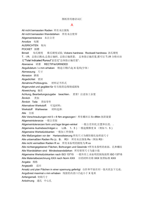
Orientation guide
AGILIS
KFB
MZB
MZE
Application
Clamping Actuation
Turning, grinding, cutting, toothcutting, balancing, etc.
internal
ROEHM罗姆精密夹具(上海)公司 电话: 021-6143 5919
邮箱:roehmchina@
expandable.
Mandrels
Table of contents
MANDRELS
Segment clamping mandrel ABSIS Accessories ABSIS
rigid system with a high portable torque for jobs with small Ø, for short clamping lengths (power-operated), high hardness of the clamping sleeve (power-operated)
7056
cost-effective system for scaling jobs, high precision
7062
yes
optional
no
hand operated
power operated
7003
Orientation guide
Mandrels
Introduction
The modern production technology can abandon heavily the employment of clamping mandrels. In the fields of finishing, turning, grinding, toothing and control, cartridge mandrels take important jobs, which are linked with ambitious aims. The different applications require a program with many variants, that reaches from hand- or poweroperated versions with morse taper mount or adapter mount, to different clamping ranges and various features like repressive clamping or workpiece stop with or without blast air controll. Additionally vulcanized clamping sleeves, whose vulcanization protects against chips and dirt, are a part of it. All products are available as special designs! Please contact us!
cylindrical mount; combinable with intermediate adapter ISO 702-1 (DIN 55028)
high hardness at the clamping sleeve; therefore wearresistant, long service life of the clamping sleeve
Segment clamping mandrel AGILIS Accessories AGILIS
Cartridge Mandrel KFB Accessories KFB MZB Accessories MZB MZE Accessories MZE
Mandrels in special design KFG HYKS
MANDRELS
Segment clamping mandrel ABSIS Cartridge Mandrel KFS Cartridge Mandrel with workstop ring MZS Segment clamping mandrel KFR Cartridge Mandrel KFR Segment clamping mandrel AGILIS Cartridge Mandrel KFB Cartridge Mandrel MZB Cartridge Mandrel MZE Mandrels in special design
Work-stop possible
10 - 130
5,5 - 29
5,5 - 78,7
8 - 230
Prepared for air sensing
Mount Features Page
cylindrical mount; combinable with intermediate adapter ISO 702-1 (DIN 55028)
7026
cylindrical mount; combinable with intermediate adapter ISO 702-1 (DIN 55028)
for short clamping lengths, suitable for defined or without axial component