123说明书
MT-1233C MT-1233D 3-1 2数字万用表用户手册说明书
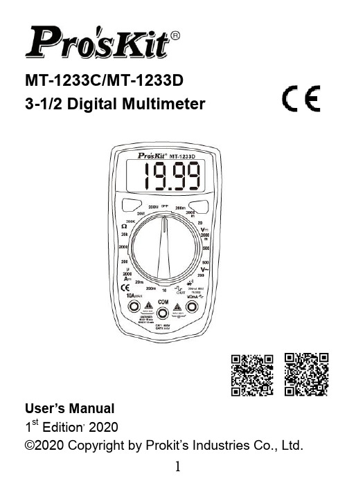
MT-1233C/MT-1233D3-1/2 Digital MultimeterUser’s Manual1st Edition, 2020©2020 Copyright by Prokit’s Industries Co., Ltd.INTRODUCTIONWarningTo avoid electric shock or personal injury, read "Safety Information" and is Warning and Precautions" before using the Mete rSafety information⏹ This series meter Comply with IEC 1010-1 CAT I600V / CAT II 300V overvoltage standards. See specifications⏹ Use the Meter only as specified in this manual,otherwise the protection provided by the Meter may be impaired.⏹ In this manual a Warming identifies conditionsand actions that pose hazards to the user.⏹ A caution identifies conditions and actions thatmay damage the meter ort he equipment under test⏹ International symbols used on the Meter and inthis manual are explained TableTo avoid possible electric shock or personal injury, and to avoid possible damage to the meter or to the equipment under test, comply with the following practices:⏹ Do not use the meter if it is damaged. Before youuse the meter, inspect the case. Pay particularattention to the insulation surrounding theconnectors.⏹ Inspect the test leads for damaged insulation orexposed metal. Check the test leads for continuity.Replace damaged test leads before you use the meter.⏹ Do not use the meter if it operates abnormally.Protection may be impaired. When in doubt, have the meter serviced.⏹ Do not operate the meter around explosive gas,vapor, or dust.⏹ Do not apply more than the rated voltage, asmarked on the meter between terminals orbetween any terminal and earth ground.⏹ Before use, verify the meter's operation bymeasuring a known voltage.⏹ When measuring current, turn off circuit powerbefore connecting the meter in the circuit.⏹ When servicing the meter, use only specifiedreplacement parts. Do not use the Meter in amanner not specified by this manual or the safety features of the meter may be impaired.⏹ Use with caution when working above 30V ac rms,42V ac peak, or 60V dc. Such voltages pose ashock hazard.⏹ When using the probes, keep your fingers behindthe finger guards on the probes.⏹ Connect the common test lead before youconnect the live test lead. When you disconnect test leads, disconnect the live test lead first.⏹ Remove the test leads from the meter before youopen the battery door. Do not operate the meterwith the battery door or portions of the coverremoved or loosened.⏹ To avoid false readings, which could lead topossible⏹ Safety Compliance: IEC 61010-1, 2000 CAT I600V overvoltage standards Do not measurevoltages above 500V in Category installations Overvoltage installations categories per IEC61010-1, 2000: The meter is designed to protect against transients in these categories:CAT I From high-voltage low-energy sources,e.g., electric circuits or a copy machine CAT II From equipment supplied from the fixed installation, e.g., TVs, PCs, portable toolsand household appliancesCAT III From equipment in fixed equipmentinstallations, e.g. installation panels,feeders and short branch circuits, andlighting systems in large buildings. General specifications◆Maximum Voltage between any Terminal andEarth Ground: 1000V◆Measurement rata: updates 2-3/sec.◆Over range indication: "1' figure only in the display ◆Automatic negative polarity indication.◆The is displayed when the battery voltagedrops below the operating voltage◆operating temperature: 0℃~40℃, 0-75% RH.◆Storage temperature: -10℃~50℃, 0-75% RH.◆Power: Single standard 1.5V battery AAAx2◆Dimensions: 130L*72W*28H mm◆Weight approx: 130g (not including battery) FRONT PANEL DESCRIPTION1. LCD Display2. DATA HOLD button3. BACK LIGHT button4. FUNCTION AND RANGE SWITCHThis switch is used to select the function and desired range as well as to turn on the instrument. To extend the life of this battery, the switch should be in the "OFF" position when the instrument is not in use.5. “VΩmA" JACK6. "10A" JACK7. "COM" JACKSPECIFICATIONSAccuracies are guaranteed for 1 year, 23℃±5 ℃, less than 80%RH200mV range and 500V DC or 500V rms for all ranges.of a sine wave.FREQUENCY RANGE: 40Hz ~400Hz OVERLOAD PROTECTION: 500V DC or 500V rms for all ranges.range unused).MEASURING VOLTAGE DROP: 200mV OVERLOAD PROTECTION: 5 second maximum 220V rms.WARNING: DO NOT input any voltage at this range for safety!WARNING: DO NOT input any voltage at this range for safety!OVERLOAD PROTECTION: 5 seconds maximum 220Vrms.WARNING: DO NOT input any voltage at resistance range for safety!302range for safety!OPERATING INSTRUCTIONSWARNING✧ To avoid electrical shock hazard and/or damageof the Instrument, do not measure voltages that might exceed 600V above earth ground.✧ Before the use of instrument, inspect test leads,connectors and probes for cracks, breaks, cracks in the insulation.✧ Dangerous voltages may be present at the inputterminals and may not be displayed.✧ To avoid electrical shock or damage to the meterwhen measuring resistance or continuity in acircuit, make sure the power to the circuit isturned off and all capacitors are discharged.DC & AC VOLTAGE MEASUREMENT1. Connect red test lead to "VΩmA" jack, Black leadto "COM" jack.2. Set RANGE switch to desired VOLTAGE position,if the voltage to be measured is not known before hand, set switch to the highest range and reduce it until satisfactory reading is obtained.3. Connect test leads to device or circuit beingmeasured.4. Turn on power of the device or circuit beingmeasured voltage value will appear on DigitalDisplay along with the voltage polarity.DC CURRENT MEASUREMENT1. Red lead lo "VΩmA". Black lead to "COM”(formeasurements between 200mA and 10A connect red lead to "10A” jack with fully depressed.)2. RANGE switch to desired DCA position.3. Open the circuit to be measured and connectedtest leads INSERIES with the load in with current is to measure.4. Read current value on Digital Display.5. Additionally,"10A"function is designed forintermittent use only. Maximum contact time ofthe test leads with the circuit is 15 seconds with a minimum intermission time of seconds between tests.RESISTANCE MEASUREMENT1. Red lead to "VΩmA". Black lead to "COM".2. RANGE switch to desired OHM position.3. If the resistance being measured is connected toa circuit, turn off power and discharge allcapacitors before measurement.4. Connect test leads LO circuit being measured.5. Read resistance value on Digital Display. DIODE MEASUREMENT1. Red lead to "VΩmA", Black lead to "COM".2. RANGE switch to "' position.3. Connect the red test lead to the anode! of thediode to be measured and black test lead tocathode.4. The forward voltage drop in mV will be displayed.If the diode is reversed, figure "1" will be shown. TEMPERATURE MEASUREMENT(MT-1233C only)1. Connect the K type thermoelectric couple to"VΩmA" and "COM" jacks.2. RANGE switch to TEMP position.3. The display will read Temperature value ℃AUDIBLE CONTINUITY TEST1. Red lead to "VΩmA", Black lead to "COM".2. RANGE switch to “”position.3. Connect test leads to two points of circuit to betested. If the resistance is lower than 30Ω±20Ω, the buzzer will sound.TEST SIGNAL USE (MT-1233D only)1. RANGE switch to "”position.2. A test signal (50Hz) appears between "VΩmA"and "COM” jack, the output voltage is approx 3V p-p with about 50KΩ impedance.MAINTENANCEBeyond replacing batteries and fuses, do not attempt to repair or service your Meter unless you are qualified to do so and have the relevant calibration, performance test and service instruments. The recommended calibration cycle is 12 months.To clean the terminalsa) Push the Meter OFF and remove test leads.b) Shake out any dirt that may be in the terminals.c) Soak a new swab with isopropyl and work around the inside of each input terminald) Use a new swab to apply a light coat of fine machine oil to the inside of each terminal. FUSES TESTWarningTo avoid electric shock or injury, remove the test leads and any input signals before replacing the fuses1. Turn the rotary switch to 200mA position.2. Use a multimeter to measure resistance of"VΩmA" terminal or 10A terminal to COM terminal.✧ A good mA terminal or 10A terminal fuse isindicated by a reading between 0Ω and 10Ω.✧ If the display is overloaded, replace the fuse andtest again.If the display shows any other value, have the meterserviced. See "Service and Parts" later in this manual.BATTERY AND FUSE REPLACEMENT1) Battery and fuse replacement should only bedone after the test leads have been disconnected and power is off.2) Loosen screws with suitable screwdriver andremove case bottom.3) The meter is powered by 1.5V battery (AAAx2).Snap the battery connector leads to the terminals of a new battery and reinsert the battery into the case top. Dress the battery leads so that they will not be pinched between the case bottom andcase top.4) The meter is protected by fast action fuse500mA/250V, dimensions is ¢5*20mm.5) Replace the case bottom and reinstall the threescrews, never operate the meter unless the case bottom is fully dosed.ACCESSORIES⏹User’s manual⏹Set of test leads(CAT I 600V work)⏹K type thermoelectric couple (MT-1233C only) SERVICE AND PARTSIf the Meter fails, check the batteries and fuses first, and then review this manual to make sure that you are operating the Meter correctly一、概述MT-1233C/D儀錶是—種功能齊全,性能穩定,結構新穎,安全可靠的小型掌上型3 1/2位元數位萬用表,可用於測量交直流電壓、直流電流、電阻、二極體正向壓降,有些還可以測量溫度和線路通斷,是廣大用戶隨身攜帶的理想維修工具。
美国芯片公司Vishay的SMD型号SOD-123 电阻产品说明书

SMD Schottky Barrier Diodes Reverse Voltage: 20 to 40 Volts Forward Current: 0.5 Amp RoHS Device
Page 1REV:AFeatures -Low turn on voltage. -Fast switching. -PN junction guard ring for transient and ESD protection.
Mechanical data -Case: SOD-123, molded plastic. -Terminals: solderable per MIL-STD-750, method 2026. -Polarity: Color band denotes cathode end. -Weight: 0.0097 gram(approx.).
CDBW0520L-HF Thru. CDBW0540-HF
Maximum Ratings and Electrical Characteristics (At Ta=25°C, unless otherwise noted)
QW-JB0102Notes: 1. Thermal resistance from junction to ambient and junction to lead, mounted on P.C.B. with 0.2×0.2 inch copper pad area.Max. repetitive peak reverse voltageMax. DC blocking voltageMax. RMS voltagePeak surge forward current, 8.3ms single half sine-wave superimposed on rate load (JEDEC method)Max. average forward currentMax. forward voltageMax. reverse currentMax. thermal resistance (Note 1)Max. operating junction temperatureStorage temperatureCDBW0520L-HFUnitsSymbolParameterVRRMVDCVRMSIFSMIOVFIRRθJARθJLTJTSTG2020140.3@IF=0.1A0.385@IF=0.5A0.075@VR=10V0.25@VR=20VVVVAAVmA°C/W°C°CCDBW0540-HF3030215.50.50.375@IF=0.1A0.430@IF=0.5A0.02@VR=15V0.13@VR=30V206150125-55 to +125Dimensions in inches and (millimeter)SOD-1230.028(0.70)0.019(0.50)0.110(2.80)0.098(2.50)0.071(1.80)0.055(1.40)0.154(3.90)0.141(3.60)0.053(1.35)0.037(0.95)0.008(0.20)Max.0.016(0.40) Min.0.005(0.12) Max.CDBW0530-HF404028
氯乙烷安全技术说明书

戴化学安全防护眼镜。
身体防护:
穿防静电工作服。
手防护:
戴橡胶耐油手套。
其他防护:
工作现场禁止吸烟、进食和饮水。工作完毕,淋浴更衣。注意个人清洁卫生。
第九部分:理化特性
外观与性状:
无色或浅黄色透明液体,有类似氯仿的气味。
pH:
熔点(℃):
相对密度(水=1):
沸点(℃):
相对蒸气密度(空气=1):
食入:
洗胃。就医。
第五部分:消防措施
危险特性:
易燃,其蒸气与空气可形成爆炸性混合物,遇明火、高热能引起燃烧爆炸。受高热分解产生有毒的腐蚀性烟气。与氧化剂接触发生反应,遇明火、高热易引起燃烧,并放出有毒气体。其蒸气比空气重,能在较低处扩散到相当远的地方,遇火源会着火回燃。
有害燃烧产物:
一氧化碳、二氧化碳、氯化氢、光气。
第十六部分:其他信息
参考文献:
填表部门:
数据审核单位:
修改说明:
其他信息:
用焚烧法处置。与燃料混合后,再焚烧。焚烧炉排出的卤化氢通过酸洗涤器除去。
废弃注意事项:
第十四部分:运输信息
危险货物编号:
32035
UN编号:
1184
包装标志:
包装类别:
O52
包装方法:
安瓿瓶外普通木箱;螺纹口玻璃瓶、铁盖压口玻璃瓶、塑料瓶或金属桶(罐)外普通木箱。
运输注意事项:
铁路运输时应严格按照铁道部《危险货物运输规则》中的危险货物配装表进行配装。运输时运输车辆应配备相应品种和数量的消防器材及泄漏应急处理设备。夏季最好早晚运输。运输时所用的槽(罐)车应有接地链,槽内可设孔隔板以减少震荡产生静电。严禁与氧化剂、酸类、碱类、食用化学品等混装混运。运输途中应防曝晒、雨淋,防高温。中途停留时应远离火种、热源、高温区。装运该物品的车辆排气管必须配备阻火装置,禁止使用易产生火花的机械设备和工具装卸。公路运输时要按规定路线行驶,勿在居民区和人口稠密区停留。铁路运输时要禁止溜放。严禁用木船、水泥船散装运输。
FITELS123M12 产品快速参考指南说明书

Stripping the Fiber CoatingFiber CleaningSafety InstructionsBefore operating this product, please read the user’s manual of safety instructions. The safety instructions are to help you use this product in a safe and correct way, and to prevent danger or injury to yourself or others.Press key. Press key. Place the ribbon fiber into the fiber holder leaving 30mm of ribbon from the edge of the holder. Use the S218R hot stripper to remove ribbon fiber coating. For detailed information, refer to the S218R operating instructions.Fiber CleavingPlace fiber holder into cleaver, then press the lever.Select applicableSelect “All Programs”.< Fusion Program>Select “Fusion PRGM ” icon from the menu.< Heater Program>Select applicable fusion program.Open the windshield and set the fibers . Select “Arc Check” icon fromthemain menu.Splicer automatically feeds the fibers anddischarges an arc.The results are indicated. If the results are negative, the machine willautomatically adjust the arc power. Please perform Arc Check is the function to adjust the arc power in order to ensure optimal splicing results. Electrode wear and environmental conditions such as temperature, humidity, and altitude, may affect the arc power.Please select SM 12 program (or applicable count SM program) before performing the Arc Check at the beginning of each daily operation.Select “Heater PRGM ”Remove both electrodes.Clean camera lens by using cotton swab soaked with ethanol.< Cleaning V-groove>< Cleaning Fiber Clamp> < Cleaning Electrodes> < Cleaning camera Lens > Clean V-groove by using a cleaning brushor a cotton swab soaked with ethanol.Run fiber across V-groove to remove dust in V-groove. Clean Fiber Clamp by using a cotton swab soaked with ethanol.Loosen the Holding Plates screws and raise the plates. Replace the electrodes. Close the windshield, and then press then key 10times.< Replacement of Electrodes>Stick the tip of anelectrode into the electrode sharpener and turn/twist the electrode 3-4 times.Fiber ClampsElectrode Sharpener Cleaning brushPower KeyTurn the power on/off.Start KeyStart/Pause/Restart the splicing process.Heating KeyStart/Stopthe heating process.Move the cursor and change the valueFunction 1 KeySelect the function shown on the left bottom corner of LCD.Function 2 KeySelect the function shown on the right bottom corner of LCD.HeaterFiber View。
FLUKE 123_124 Users Manual 福禄克123_124使用手册 说明书
Fluke Industrial B.V., P.O. Box 90, 7600 AB, Almelo, The Netherlands
SERVICE CENTERS
To locate an authorized service center, visit us on the World Wide Web:
THIS WARRANTY IS BUYER'S SOLE AND EXCLUSIVE REMEDY AND IS IN LIEU OF ALL OTHER WARRANTIES, EXPRESS OR IMPLIED, INCLUDING BUT NOT LIMITED TO ANY IMPLIED WARRANTY OF MERCHANTABILITY OR FITNESS FOR A PARTICULAR PURPOSE. FLUKE SHALL NOT BE LIABLE FOR ANY SPECIAL, INDIRECT, INCIDENTAL OR CONSEQUENTIAL DAMAGES OR LOSSES, INCLUDING LOSS OF DATA, WHETHER ARISING FROM BREACH OF WARRANTY OR BASED ON CONTRACT, TORT, RELIANCE OR ANY OTHER THEORY.
Fluke authorized resellers shall extend this warranty on new and unused products to end-user customers only but have no authority to extend a greater or different warranty on behalf of Fluke. Warranty support is available if product is purchased through a Fluke authorized sales outlet or Buyer has paid the applicable international price. Fluke reserves the right to invoice Buyer for importation costs of repair/replacement parts when product purchased in one country is submitted for repair in another country.
M 123 Flow meter说明书

123312Flow meter M 123Measuring ranges 1.5 - 1,000 l/hM123 PVCM 123 PVDF M 123 PSU FUnCTIon The M 123 flow meter works on the float principleand is used to measure the flow rate in closed pipelines.The medium flows through the vertically installed flow meter from bottom to top. Thisraises the float and shows the current flow rate on the scale on the measuring device. The read-off edge corresponds to the largest diameter of the float.The M 123 flow meters have a water scale and 2 setpoint indicators as standard.SpECIAl FEATURES• Fracture-proof and corrosion-resistant • Radially removable• Adhesive special scales, for liquid and gaseous media• Holder for accessories (limit value contacts) • Measuring tube carries the DN label, and also the measuring range and material • PVDF floats and stops as standard • Measuring ranges 1.5-1,000 l/h• Less space required thanks to short overall length • Operating pressure PN 10 at 20 °CMATERIAlSMeasuring tubeFloatInsert, top and bottomO-ringPVC PVDF PVDFEPDM (standard), FPM(optional)PSUPVDFPVDFEPDM (standard), FPM (optional) PVDF PVDF PVDFFPM (standard)2MEASURInG ACCURACyAccuracy Class 4 as defined by VDE/DIN 3513 page 2Flow in %10203040506o708090100Total measured value error in %13.008.00 6.33 5.50 5.oo 4.67 4.43 4.25 4.11 4.00Total limit value error in %1.31.61.92.22.52.93.13.43.74.0pRESSURE loSSMeasuring range l/h1.5-152.5-255-5010-1008-8015-15020-20015-15030-30050-500100-1,000Pressure loss mm WS 46.046.046.046.044.744.744.782.882.882.882.8Measuring range l/h1.5-152.5-255-5010-1008-8015-15020-20015-15030-30050-500100-1,000Pressure loss mbar 4.6 4.6 4.6 4.6 4.47 4.47 4.478.288.288.288.28operating pressure: max. PN 10 at 20 °CFloAT-TypE Flow METERdDNMeasuring range H 2OM 1231610 1.5- 15■ ●1610 2.5 -25■ ● ▲1610 5 - 50■ ● ▲161010 - 100■ ● ▲20158 - 80■ ● ▲201515 - 150■ ● ▲201520 - 200■ ● ▲322515 - 150■ ● ▲322530 - 300■ ● ▲322550 - 500■ ● ▲3225100 -1,000■ ● ▲TEMpERATURE RAnGEMeasuringtubeScrew connectionMax. temp. at 1 barPVC-U PVC-U 0 - 60 °C PA PVC-U 0 - 60 °C PSU PVC-U 0 - 60 °C PSU PVDF 0 - 90 °C PVDF PVDF 0 - 100 °CKey to symbols: ■ PSU (Polysulphone), ● PVC, ▲ PVDFConnECTIon poSSIbIlITIESSocketSpigotPlastic female threadMetal female threadPVC adhesive socket (standard)PP fusion socket PVC Stainless steel V4A PP fusion spigot PVDF fusion spigot PP Malleable cast ironPVDF fusion socketPE fusion spigotPVDF34Measuring range l/hH 2 OAdhesive socketFusion socket Spigot PP Threaded socket dDN Gd üLd mzL md mzL mdL gSdL gI g1.5 -152.5- 25 5 - 50 10 - 10016103/4"351651617119915.5 1752013/8" 199118 - 80 15 150 20 20020151"431852019122319.5 19522320293 1.91/2"2231315 - 150 30 - 300 5o - 5oo 10o 1,oo03225 1 1/2"602003620625031.5 21024632320 3.01"25017SpECIAl SCAlESMeasuring range Air o bar Air 1 bar Air 2 bar Air 3 barO l/h Art.-No.N m3/h Art.-No.N m3/h Art.-No.N m3/h Art.-No.N m3/hH21.5 - 1500.000.9980.10 - 0.5500.001.0500.15 - 0.8000.001.0510.17 - 0.900.001.0520.20 - 1.12.5 - 2500.001.0590.2 - 0.95oo.oo1.o6o0.25 - 1.3oo.oo1.o610.3 - 1.600.001.0620.4 - 1.95 - 50oo.oo1.o7o0.5 - 1.900.001.0710.7 - 2.700.001.0720.8 - 3.400.001.073 1.0 - 3.8 10 - 100oo.oo1.o810.8 - 3.000.001.082 1.0 - 4.200.001.083 1.2-5.400.001.084 1.4 - 6.48 - 8o00.001.0920.6 - 2.800.001.0930.8 - 400.001.094 1.o - 5.o00.001.095 1.2 - 5.6 15 - 15000.001.103 1.4 - 5.6oo.oo1.1o4 2 - 800.001.105 2 - 10oo.oo1.1o6 3 - 1220 - 200oo.oo1.114 1.5 - 7.0oo.oo1.115 2 - 10oo.oo1.116 3 - 1300.001.117 3 - 1515 - 15000.001.125 1.0 - 6.500.001.126 1 - 9000.001.127 1.5 - 1100.001.128 2 - 1330 - 30000.001.136 1.5 - 1100.001.137 2 - 1500.001.138 2.5 - 1800.001.139 3 - 2250 - 50000.001.147 3 - 1800.001.148 4 - 2500.001.149 5 - 30 00.001.150 5 - 35 100 - 1,00000.001.158 6 - 3000.001.1598 - 44oo.oo1.16o10 - 54 oo.oo1.161 12 - 62 Measuring range Air 4 bar Air 5 bar Air 6 bar Air 7 barO l/h Art.-No.N m3/h Art.-No.N m3/h Art.-No.N m3/h Art.-No.N m3/hH21.5 - 1500.001.0530.25 - 1.2000.001.0540.25 - 1.3oo.ooo.9990.26 - 1.4500.001.0550.30 - 1.52.5 - 2500.001.0630.4 - 2.100.001.0640.5 - 2.400.001.0650.5 - 2.5oo.oo1.o660.5 - 2.75 - 5000.001.074 1.2 - 4.200.001.075 1.2 - 4.600.001.076 1.2 - 5.0oo.oo1.077 1.4 - 5.4 10 - 10000.001.085 1.6 - 7.0oo.oo1.o86 1.6 - 7.400.001.087 2.0 - 8.0oo.oo1.o88 2 - 8.88 - 8o00.001.096 1.4 - 6.400.001.097 1.4 - 7.000.001.098 1.5 - 7.500.001.099 1.5 - 8.0 15 - 150oo.oo1.107 3 - 13oo.oo1.1o8 3 - 1400.001.109 3.5 - 1500.001.110 3.5 - 16.5 20 - 20000.001.118 4 - 17oo.oo1.119 4 - 1800.001.120 4 - 2000.001.121 5 - 2115 - 15000.001.129 2 - 14.500.001.130 2 - 16oo.oo1.131 2 - 1700.001.132 2.5 - 1830 - 30000.001.140 3 - 2400.001.141 4 - 2600.001.142 4 - 2800.001.143 4 - 3050 - 50000.001.151 6 - 4000.001.152 6 - 4400.001.1538 - 4800.001.1548 - 50 100 - 1,00000.001.16212 - 70oo.oo1.16315 - 75oo.oo1.16415 - 8o00.001.16515 - 85 Measuring range Air 8 bar Air 9 bar Air 10 barO l/h Art.-No.N m3/h Art.-No.N m3/h Art.-No.N m3/hH21.5 - 1500.001.0560.3 - 1.600.001.0570.3 - 1.700.001.0580.35 - 1.82.5 - 2500.001.0670.6 - 2.9oo.oo1.o680.6 -3.000.001.0690.6 - 3.25 - 5000.001.078 1.4 - 5.800.001.079 1.6 - 6.0 oo.oo1.o8o 1.6 - 6.410 - 10000.001.089 2.0 - 9.000.001.090 2 - 1000.001.091 2 - 108 - 8o00.001.100 1.5 - 8.500.001.101 2.0 - 9.000.001.102 2.0 - 9.515 - 15000.001.111 4 - 1700.001.112 4 - 18oo.oo1.113 4 - 1920 - 20000.001.122 5 - 2300.001.123 5 - 2300.001.124 5 - 2515 - 15000.001.133 2.5 - 19.500.001.134 3 - 2000.001.135 3 - 2130 - 30000.001.144 4 - 3300.001.145 5 - 3400.001.146 5 - 3550 - 500 oo.oo1.1558 - 5400.001.1568 - 5600.001.1571o - 6o100 - 1,000oo.oo1.16620 - 9000.001.16720 - 95oo.oo1.16820 - 1005123SpECIAl SCAlES H 2o wITH oTHER UnITS oF MEASUREMEnTMeasuring range Series M 123dDNl/hArt.-No.USGPMSpecial scales as requested by the customerDetails required: Medium, spec. weight in g/cm 3, viscosity in cP or mPas, operating temperature in °C, desired measuring range in l/h. ACCESSoRIESLimit value contact Z 40 min.Limit value contact Z 42 max.InSTAllATIon AnD ASSEMbly InSTRUCTIonS• Install the flow meter into the pipeline system vertically and without tension.• Provide an inlet and outlet sectionInlet approx. 10 x DN, outlet approx. 5 x DN.noTES on opERATIon• Avoid pressure surges, as these can damage the unit.• Exercise caution when installing. The measuring tube must not come into contact with solvent.• Before start-up, make sure that the connected parts are sufficiently tightened.• The union nuts must not be mixed up on ameasuring tube made from the material PVDF . The overall length also does not correspond to the dimensions table.We reserve the right to make technical changes in the interest of improvement.SpECIAl SCAlESMeasuring range HCI 30-33 % (PSU)NaOH 30 %NaOH 50 %H 2O l/hArt.-No.l/hArt.-No.l/hArt.-No.l/h1.5 - 1500.005.1171 - 1000.005.1440.1 - 2.0––2.5 - 25oo.o05.118 2.5 - 2000.005.1450.2 - 5––5 - 5000.005.119 5 - 4000.005.128 1 - 14––10 - 10000.005.12010 - 8500.005.129 3 - 35––8 - 8000.005.1218 - 7000.005.130 2 - 23oo.oo5.1370.2 - 3.515 - 15000.005.12215 - 12500.005.131 3 - 5500.005.1380.5 - 1020 - 20000.005.12320 - 17000.005.132 5 - 8000.005.139o.5 - 1615 - 15000.005.124 5 - 12500.005.133 3 - 5500.005.140o.5 - 1130 - 300oo.oo5.12530 - 26000.005.134 6 - 13000.005.141 1 - 3350 - 50000.005.12650 - 42500.005.13510 - 25000.005.142 2 - 80100 - 1,000oo.oo5.127100 - 85000.005.13640 - 60000.005.14310 - 220Application instructions for special scalesWhen applying special scales later, ensure that the marking on the scale corresponds with the one on the measuring tube.▼pRESSURE CoRE TAblE FoR GASES: CAlIbRATIon pRESSURE o bAR Operatingpressure in barFactor xdisplay valueOperatingpressure in barFactor xdisplay value0.0 1.000 3.0 2.0000.2 1.095 4.0 2.2400.4 1.184 5.0 2.450o.6 1.265 6.0 2.6500.8 1.3407.0 2.8301.0 1.4148.0 3.ooo 1.5 1.5809.0 3.1652.01.73010.03.32064042limit value contact Z 40 min. / Z 42 max. For float-type flow metersM 335 / M 350 / M 123/ M23 PVDFUSEThe limit value contacts Z 40 and Z 42 are used for external monitoring of limited flow values on our (float-type) flow meters. They are pushed onto the guide rod located on the flow meter and can be adjusted to any desired value on the corresponding scale.SwITCHInG STATESFloat above Float belowZ 40 min open closedZ 42 max closed openAttentionWhen retrofitting the flow meter with limit value contacts, ensure that the standard float is replaced with a solenoid float. The solenoid float is clearly identified by an “M” on the top.oRDER nUMbERSZ 40 min. 17.100.686Z 42 max. 17.100.687TECHnICAl DATASwitching voltage* max. 230 V~Switching rating* max. 10 W/12 VA Switching current* max. 0.5 AContact resistance < 200 mOhmLeakage resistance > 1011 OhmPermissible ambient o to + 55°CtemperatureProtection type in ace. withDIN 40050-IP 65 Switching hysteresis 1 - 2 mm float travelWe reserve the right to make technical changes in the interest of improvement.* Even a brief overshoot is not permitted. This is uncontrollable with inductive or capacitive peaks, e.g. with contactors or solenoid valves. It is therefore recommended to use a limit value switch or a contact protection relay.FUnCTIonA solenoid installed in the float closes or opens a reedcontact permanently cast in the limit value contact.The switching function is bistable. This means that theswitching state is maintained even if the solenoid floatmoves away from the contact.The technical data is non-binding. It is not to be regarded as representing assured properties or as a guarantee of quality or durability. We reserve the right to make changes.Our general terms of sale apply.7Herbert-Frank-Straße 26 I 72178 Waldachtal I GermanyP R E M I U M-QUALITY PLASTIC。
石灰石取料机说明书123
YG500/90混匀堆取料机产品说明书D705ASM(机械部分)沈阳矿山机械有限责任公司目录1设备简图 (2)2用途 (2)3主要技术性能参数 (2)4基本构造和工作原理 (3)5操作使用 (4)6维护和检修 (5)7拆卸与组装 (9)8常见故障、原因、修正措施 (13)9润滑 (17)10安装 (19)11试车 (24)12易损件明表 (26)13轴承明细表 (27)1、设备简图2、设备用途本机适用于海螺石灰石预均化堆场。
本机可同时或分别完成物料的混匀堆料和混匀取料作业。
本机安装在室内工作。
3、主要技术性能参数3.1. 物料特性物料种类石灰石物料容重 1.45t/m3物料粒度0-80mm(占85%)堆积角38°3.2. 料场参数取料机轨道直径φ90m取料机轨道型号QU80均化比10:1料场总储量52000 t料场有效储量47000 t3.3. 堆料机性能参数堆料方式连续合成式堆料层数>500 层堆料能力1500t/h料堆半径23m堆料胶带机带宽1200m堆料胶带机带速 2.5m/s堆料胶带机功率55KW变幅角度-16°~+14°变幅油泵电机功率15KW堆料机回转角速度0.11744r/min回转电机功率4KW3.4. 取料机性能参数取料型式全断面取料取料能力500t/h取料机工作运行速度0.0056~0.056m/min取料机调车运行速度 3.48m/min取料运行电机功率2³0.55KW调车运行电机功率2³3KW刮板尺寸(长³宽) 1700³330mm刮板间距630mm刮板链速0.51m/s刮板驱动电机功率90KW料耙驱动方式液压驱动料耙可调角度34°~45°料耙运行速度0.2m/s料耙驱动电机功率45KW3.5. 电器性能参数动力电压380V,50Hz控制电压220V,50Hz控制方式PC程控、手控总装机功率235KW4、基本构造和工作原理YG500/90圆料场混匀堆取料机的基本构造是由中柱,可在中柱上回转的堆料机和一端绕中柱回转、另一端在圆形轨道上运行的刮板取料机组成。
昂纬电子 SOD-123 表面挂载 Schottky 障碍电子说明书
SURFACE MOUNT SCHOTTKY BARRIER DIODEFeatures• Low Forward Voltage Drop• Guard Ring Construction for Transient Protection• Fast Switching Time• Low Reverse Capacitance• Surface Mount Package Ideally Suited for Automated Insertion • Lead, Halogen and Antimony Free, RoHS Compliant "Green" Device (Notes 3 and 4)Mechanical Data• Case: SOD-123• Case Material: Molded Plastic. UL Flammability Classification Rating 94V-0• Moisture Sensitivity: Level 1 per J-STD-020D• Terminals: Solderable per MIL-STD-202, Method 208• Lead Free Plating (Matte Tin Finish annealed over Alloy 42 leadframe)• Polarity: Cathode Band• Marking Information: See Page 2• Ordering Information: See Page 2• Weight: 0.01 grams (approximate)Top ViewMaximum Ratings@T A = 25°C unless otherwise specifiedCharacteristic Symbol Value UnitPeak Repetitive Reverse Voltage Working Peak Reverse Voltage DC Blocking Voltage V RRMV RWMV R70 VRMS Reverse Voltage V R(RMS)49 V Maximum Forward Current I FM15 mAThermal CharacteristicsCharacteristic Symbol Value Unit Power Dissipation (Note 1) P D333 mW Thermal Resistance, Junction to Ambient Air (Note 1) RθJA300 °C/W Operating Temperature Range T J-55 to +125 °C Storage Temperature Range T STG-55 to +150 °CElectrical Characteristics@T A = 25°C unless otherwise specifiedCharacteristic Symbol Min Typ Max Unit Test Condition Reverse Breakdown Voltage (Note 2) V(BR)R70 ⎯⎯V I R = 10μAForward Voltage Drop V F⎯⎯0.411.00VI F = 1.0mAI F = 15mAReverse Leakage Current (Note 2) I R⎯⎯200 nA V R = 50VTotal Capacitance C T⎯⎯ 2.0 pF V R = 0V, f = 1.0MHzReverse Recovery Time t rr⎯⎯ 1.0 ns I F = I R= 5.0mAI rr = 0.1 x I R, R L = 100ΩNotes: 1. Part mounted on FR-4 board with recommended pad layout, which can be found on our website at /datasheets/ap02001.pdf.2. Short duration pulse test used to minimize self-heating effect.3. No purposefully added lead. Halogen and Antimony Free.4. Product manufactured with Data Code V9 (week 33, 2008) and newer are built with Green Molding Compound. Product manufactured prior to Date Code V9 are built with Non-Green Molding Compound and may contain Halogens or Sb2O3 Fire Retardants.Please click here to visit our online spice models database.0.11.010V , INSTANTANEOUS FORWARD VOLTAGE (V)Fig. 1 Typical Forward Characteristics F I , I N S T A N T A N E O U S F O R W A R D C U R R E N T (m A )F 100101001,00010,000V , INSTANTANEOUS REVERSE VOLTAGE (V)Fig. 2 Typical Reverse Characteristics R I , I N S T A N T A N E O U S R E V E R S E C U R R E N T (n A )R01.41.21.0C , T O T A L C A P A C I T A N C E (p F )T V , DC REVERSE VOLTAGE (V)Fig. 3 Total Capacitance vs. Reverse Voltage R 350P , P O W E R D I S S I P A T I O N (m W )D T , AMBIENT TEMPERATURE (°C)Fig. 4 Power Derating CurveA 200Ordering Information (Note 5)Part Number Case Packaging1N5711W-7-FSOD-123 3000/Tape and ReelNotes: 5. For packaging details, go to our website at /datasheets/ap02007.pdf.Marking InformationSA = Product Type Marking Code YM = Date Code Marking Y = Year (ex: T = 2006)M = Month (ex: 9 = September)SA Y MDate Code KeyYear 1998 1999 2000 2001 2002 20032004200520062007200820092010 2011 2012 201320142015CodeJ K L M N P R S TUVWX Y Z A B CMonth Jan Feb Mar Apr May Jun Jul Aug Sep Oct Nov Dec Code 1 2 3 4 5 6 7 8 9 O N DPackage Outline DimensionsSuggested Pad LayoutIMPORTANT NOTICEDiodes Incorporated and its subsidiaries reserve the right to make modifications, enhancements, improvements, corrections or other changes without further notice to any product herein. Diodes Incorporated does not assume any liability arising out of the application or use of any product described herein; neither does it convey any license under its patent rights, nor the rights of others. The user of products in such applications shall assume all risks of such use and will agree to hold Diodes Incorporated and all the companies whose products are represented on our website, harmless against all damages.LIFE SUPPORTDiodes Incorporated products are not authorized for use as critical components in life support devices or systems without the expressed written approval of the President of Diodes Incorporated.SOD-123Dim Min Max A 0.55 Typ B 1.40 1.70 C 3.55 3.85 H 2.55 2.85 J 0.00 0.10 K 1.00 1.35 L 0.25 0.40 M 0.10 0.15α0 8° All Dimensions in mmZXCG YDimensions Value (in mm)Z 4.9 G 2.5 X 0.7 Y 1.2 C 3.7。
火灾显示盘 FW123H 产品说明书
FW123H 火灾显示盘目录概述 (3)简介 (3)特性 (3)规格参数及特性 (3)安装及调试 (3)安装 (4)接线 (4)操作界面说明 (8)界面说明 (8)常见故障分析及维护 (13)简介FW123H型火灾显示盘用于对楼层或独立防火区内的火灾报警,当火灾报警控制器产生报警时,火灾报警控制器同时把报警信号传输到失火区域的火灾显示盘上,显示盘会显示报警的探测器编号及相关信息并发出报警声响。
FW123H型火灾显示盘安装在楼层或独立防火区内,可以接收多台控制器的火灾报警信息并作出相应的报警提示。
FW123H型火灾显示盘执行标准为GB17429-2011《火灾显示盘》。
特性1)FW123H与FW109型火灾报警控制器通过联网卡XNU的CAN总线连接。
当有火警、故障、屏蔽时,火灾显示盘能实时接收火灾报警控制器从通讯线传输的火警、故障、屏蔽信号,并发出对应的声指示和光指示信号;2)FW123H采用7英寸高分辨率液晶屏,显示信息丰富,显示效果清晰;3)FW123H具有中文注释功能,报警时在液晶显示屏上可显示具体的报警地址号和预先保存的中文注释;4)FW123H具有以太网接口,支持以太网下载中文注释,和在线升级程序;5)FW123H具有自检功能,可以自动检测火灾显示盘上的状态指示灯、液晶屏和扬声器;6)FW123H具有中英法三种语言切换功能,可以通过菜单切换显示的语言。
7)FW123H具有确认状态显示功能,已被控制器确认的事件信息可在火灾显示盘显示。
8)FW123H具有火警、故障、屏蔽信号24小时重响功能。
9)FW123H具有屏蔽指示功能、接地状态指示功能、声光消音状态功能。
10)FW123H具有配置共享功能。
可将组网系统中的任意火灾报警控制器或火灾显示盘的配置信息一键共享至所有联网的火灾报警控制器及火灾显示盘上。
11)FW123H可查询所有组网控制器的属性及配置信息,如软件版本号、回路配置、回路在线状态、地址屏蔽信息等。
ZGM-113G型磨煤机说明书(123)解读
第一篇磨煤机使用和操作说明1. 代号和技术数据1.1 代号分K、N、G三个型号,N型,不表示磨环滚道平均半径(cm)磨煤机辊式中速1.2 技术数据1.2.1 煤种范围煤种烟煤,部分贫煤和部分褐煤发热量16~31MJ/kg表面水份≤18%可磨性系数HGI=40~80(哈氏)可燃质挥发份16~40%原煤颗粒0~40mm煤粉细度R90=10~40%1.2.2 磨煤机技术数据标准研磨出力58 t/h (DL/T 5145-2002 标准)额定功率512 kW电动机额定功率560 kW电动机电压6000 V电动机转速990 r/min电动机旋转方向逆时针(正对电机输入轴)磨煤机磨盘转速24.4 r/min磨煤机旋转方向顺时针(俯视)通风阻力≤6410 Pa磨机额定空气流量25.14 kg/s磨煤机磨煤电耗量6~10 kW·h/t (100%磨煤机出力)2. 工作原理ZGM113磨煤机是一种中速辊盘式磨煤机,其碾磨部分是由转动的磨环和三个沿磨环滚动的固定且可自转的磨辊组成。
原煤从磨机的中央落煤管落到磨环上,在离心力作用下将原煤运动至碾磨滚道上,通过磨辊进行碾磨。
三个磨辊沿圆周方向均布于磨盘滚道上,碾磨力则由液压加载系统产生,通过静定的三点系统,碾磨力均匀作用至三个磨辊上,这个力是经磨环、磨辊、压架、拉杆、传动盘、减速机、液压缸后通过底板传至基础(见图1―1)。
原煤的碾磨和干燥同时进行,一次风通过喷嘴环均匀进入磨环周围,将从磨环上切向甩出的煤粉吹送至磨机上部的分离器,在分离器中进行分离,粗粉被分离出来返回磨环重磨,合格的细粉被一次风带出分离器。
图1―1 磨煤机加载传递系统“受力状态图”难以粉碎且一次风吹不起的较重石子煤、黄铁矿、铁块等通过喷嘴环落到一次风室,被刮板刮进排渣箱,由人工(或由自动排渣装置排走)定时清理。
(见图1―2)。
ZGM113型磨煤机采用鼠笼型异步电动机驱动。
通过立式伞齿轮行星齿轮减速机传递力矩。
- 1、下载文档前请自行甄别文档内容的完整性,平台不提供额外的编辑、内容补充、找答案等附加服务。
- 2、"仅部分预览"的文档,不可在线预览部分如存在完整性等问题,可反馈申请退款(可完整预览的文档不适用该条件!)。
- 3、如文档侵犯您的权益,请联系客服反馈,我们会尽快为您处理(人工客服工作时间:9:00-18:30)。
The Group’s 2,016 employees are involved in the quality process on a daily basis for consumer safety and are instrumental in the continuous
improvement of the quality of products and related services. Our Group is pursuing the process to acquire IFS (International Food Standard) and BRC (Retail Consumer) certification. To date, all our sites are certified to IFS and BRC (except Carod, to IFS only), i.e. a capacity of over 3 million bottles a day. This represents over 50 days of audit p.a. for the group (30 days of internal audit and 21 days of certification audit).
Serge Melchior, Site manager
u
u
u
u
u
u
Storage and retrieval facilities: 6 000 barrels
u
u
u
u
u
u
u
7
The
str engths of
the
GCF G r o up
SPECIALIST INTO BAG IN BOX & PLASTIC BOTTLE PRODUCTION
1 st French exporter with 16,8% export market share. Presence into over 165 countries.
Joseph Helfrich Annual revenues in 2014 were €927 - 24% in France - 76% in the export market: • Germany: 28% • UK: 10,5% • World Exports: 23% The GCF Group employs
u
170 millions bottles Site area: Indoor area: Fermentation capacity: Storage facility: 2 Transtockeurs Bottling lines: PET line: Capacity/day: BIB lines: Capacity/year: Crémant de Bordeaux lines: Capacity/year: 72 ha 85 000 m2 more than 250 000 hl 65 000 m2 26 million bottles 6 1 1 300 000 bottles 3 18 million BIB 1 5 million BIB
u
u
u
Production site - Landiras
u
u
BIB lines: Capacity/year:
3 18 million BIB
u
8
The
str engths of
the
GCF G r o up
AUTOMATIC STORAGE WAREHOUSE
Objective:• NhomakorabeaStable growth and internal rationalisation for maximum productivity
u
Fermenting room Vinification centre
C
u
Société Fermière des Grands Crus de France
B
DIOIS u Carod SAS
V V
u
Domaine de Guigouret
LANGUEDOC ROUSSILLON
u
Domaine de La Baume
G R A N D S C H A I S D E F R A N C E G RO U P 2015
WHO AR E W E?
The Grands Chais de France Group is a family concern by the C.E.O. Joseph Helfrich . GCF Group is one of
C
u
Les Grands Chais de France
L
u
Dulong
S
Bordeaux
Valence
BEAUJOLAIS u Pasquier Desvignes
R T
Domaine Viticole de la Ville de Colmar
C
u
Calvet
B
-S
Nîmes Montpellier
S
u
Château Seguala
T
RHÔNE
u
u
Domaine de Tholomiès
L L
Château de La Tuilerie
N
4
A G RO U P AT T H E L E A D I N G E D G E O F P RO G R E S S
5
The
str engths of
Les Grands Chais de France
P������ ��� (HQ)
LOIRE VALLEY u Lacheteau
M D R B
u
Paris
ALSACE
Strasbourg
STRASBOURG
u
F
,T
,V
,V
Maison Arthur Metz
M Fermenting room Vinification centre S I Fermenting room Vinification centre
COPPENHAGUE
European leading French Wine supplier with dedicated Sales team in the countries (over 200 sales persons)
MOSCOU LONDRES AMSTERDAM DÜSSELDORF BRUXELLES FRANCFORT HECHTSHEIM PRAGUE BERLIN VARSOVIE
PARIS NANTES
PETERSBACH
VIENNE ZURICH
BORDEAUX
LYON
MARSEILLE
BARCELONE MADRID ROME
ATHÈNES
3
REGIONAL OP ERATI ON S THROU G H O U T F R A N C E
THE GROUP IS PRESENT IN 9 WINE GROWING REGIONS OF FRANCE.
Production site - Petersbach
u
Single serve production (18,7cl/20cl/25cl/…) 2 10 million BIB
u
BIB lines: Capacity/year:
60 Millions units Glass specific shape, 187 ml & 250 ml Plastic PET specific shape multi-layer 2 proper blowing machines
million,
split:
2,016 people in 28 companies located regionaly.
2
GEOGR APHI C SI TU ATI ON
The group’s head office and main production site are in Petersbach, at the heart of the Vosges du Nord national park in Alsace, a perfect geographic location in the centre of Europe. In addition, the Group has operations in the major wine-growing regions of France.
satisfaction through faster service
9
The
str engths of
the
GCF G r o up
ADVANCED LOGISTICS
ASIA World Exports
Le Havre Rotterdam Anvers
Germany + Eastern Europe
M
id
dl
e-
E
as
t
U
ica
France United Kingdom Russia World Export
SA
10
The
str engths of
the
GCF G r o up
THE GCF GROUP’S COMMITMENT TO QUALITY
Figures:
Initiated in September 2004, certification processes have and will continue to engage the commitment and support of all GCF employees.