Primary side controller for regulated power converters - US5335162A
LTC3706EGN#PBF;LTC3706EGN#TRPBF;LTC3706IGN#PBF;LTC3706IGN#TRPBF;中文规格书,Datasheet资料

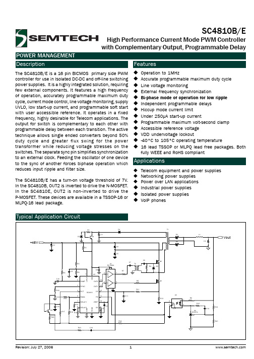
13706fdTYPICAL APPLICATIONDESCRIPTIONForward Controller with PolyPhase CapabilityThe L TC ®3706 is a PolyPhase capable secondary-side controller for synchronous forward converters. When used in conjunction with the L TC3705 gate driver and primary-side controller , the part creates a complete isolated power supply that combines the power of PolyPhase operation with the speed of secondary-side control.The L TC3706 has been designed to simplify the design of highly efficient, secondary-side forward converters. Working in concert with the L TC3705, the L TC3706 forms a robust, self-starting converter that eliminates the need for the separate bias regulator that is commonly used in secondary-side control applications. In addition, a pro-prietary scheme is used to multiplex gate drive signals and DC bias power across the isolation barrier through a single, tiny pulse transformer .The L TC3706 provides remote sensing, accurate power good and overvoltage monitoring circuits to support preci-sion, high current applications. A linear regulator controller with thermal protection is also provided to simplify the generation of secondary-side bias voltage.The L TC3706 is available in a 24-lead SSOP package.36V-72V to 3.3V/20A Isolated Forward ConverterFEATURESAPPLICATIONSnIsolated 48V Telecommunication Systems n Internet Servers and Routersn Distributed Power Step-Down Converters nAutomotive and Heavy EquipmentnSecondary-Side Control for Fast T ransient Response n Self-Starting Architecture Eliminates Need for Separate Bias Regulatorn Proprietary Gate Drive Encoding Scheme Reduces System Complexityn PolyPhase ® Operation Reduces C INRequirements n Current Mode Control Ensures Current Sharing n PLL Fixed Frequency: 100kHz to 500kHz n ±1% Output Voltage Accuracy n T rue Remote Sense Differential Amplifier n Power Good Output Voltage Monitor n High Voltage Linear Regulator Controller n Wide Supply Range: 5V to 30Vn Available in a Narrow 24-Lead SSOP PackageV IN –V IN +3OUT –OUT +L , L T , L TC, L TM, PolyPhase, Burst Mode, Linear Technology and the Linear logo are registered trademarks and No R SENSE and ThinSOT are trademarks of Linear Technology Corporation. All other trademarks are the property of their respective owners. Protected by U.S. Patents including 6144194, other patents pending./23706fdPIN CONFIGURATIONABSOLUTE MAXIMUM RATINGSV CC ........................................................... –0.3V to 10V V IN ........................................................... –0.3V to 33V SW ............................................................... –5V to 50V NDRV ......................................................... –0.3V to 13V ITH, RUN/SS, V SOUT , V S +, V S –, REGSD ....... –0.3V to 7VAll Other Pins ............................................ –0.3V to 10VOperating Temperature Range (Note 2) LTC3706E GN .......................................–40°C to 85°C LTC3706IGN ........................................–40°C to 85°C Junction Temperature (Note 3) ............................ 125°C Storage Temperature Range ..................–65°C to 150°C Lead Temperature (Soldering, 10 sec) ...................300°C(Note 1)ORDER INFORMATIONLEAD FREE FINISH TAPE AND REEL PART MARKING PACKAGE DESCRIPTION TEMPERATURE RANGE L TC3706EGN#PBF L TC3706EGN#TRPBF L TC3706EGN 24-Lead Plastic SSOP –40°C to 85°C L TC3706IGN#PBF L TC3706IGN#TRPBF L TC3706IGN 24-Lead Plastic SSOP –40°C to 85°C LEAD BASED FINISH TAPE AND REEL PART MARKING PACKAGE DESCRIPTION TEMPERATURE RANGE L TC3706EGN L TC3706EGN#TR L TC3706EGN 24-Lead Plastic SSOP –40°C to 85°C L TC3706IGNL TC3706IGN#TRL TC3706IGN24-Lead Plastic SSOP–40°C to 85°CConsult L TC Marketing for parts specified with wider operating temperature ranges.For more information on lead free part marking, go to: http://www.linear .com/leadfree/For more information on tape and reel specifications, go to: http://www.linear .com/tapeandreel//ELECTRICAL CHARACTERISTICSThel indicates specifications which apply over the full operating temperature range, otherwise specifications are at T A = 25°C. V CC = 7V, V IN = 15V, GND = PGND = 0V, unless otherwise noted.SYMBOL PARAMETER CONDITIONS MIN TYP MAX UNITS Main Control LoopV FB Regulated Feedback Voltage(Note 4) ITH = 1.2V l0.5940.6000.606V I FB Feedback Input Current(Note 4)2100nA ∆V FB(LINREG)Feedback Voltage Line Regulation V IN = 6V to 30V, ITH = 1.2V0.001%/V ∆V FB(LOADREG)Feedback Voltage Load Regulation Measured in Servo Loop,ITH = 0.5V to 2Vl–0.01–0.1%V ISMAX Maximum Current Sense Threshold R SENSE Mode, 0V < V IS– < 5VV IS– = V CC, 0V < V IS+ < 2V (CT Mode)681.15781.28881.4mVVV ISOC Over-Current Shutdown Threshold R SENSE Mode, 0V < V IS– < 5VV IS– = V CC, 0V < V IS+ < 2V (CT Mode)871.451001.651131.85mVVg m T ransconductance Amplifier g m 2.40 2.75 3.10mS I RUN/SS(C)Soft-Start Charge Current V RUN/SS = 2V–4–5–6µA I RUN/SS(D)Soft-Start Discharge Current3µA V RUN/SS RUN/SS Pin On Threshold V RUN/SS Rising l0.40.450.5V t ON,MIN Minimum On-Time200ns FG, SG R UP FG, SG Driver Pull-Up On Resistance FG, SG Low 1.5 2.7ΩFG, SG R DOWN FG, SG Driver Pull-Down On Resistance FG, SG High 1.5 2.7ΩPT+, PT– R UP PT+, PT– Driver Pull-Up Resistance PT+, PT– Low 1.5 2.7ΩPT+, PT– R DOWN PT+, PT– Driver Pull-Down Resistance PT+, PT– High 1.5 2.7Ω∆V FB(OV)Output Overvoltage Threshold V FB Rising151719% V CC SupplyV CCOP Operating Voltage Range510V V CCREG Regulated Output Voltage 6.67.07.4VI CC Supply CurrentOperatingShutdown f OSC = 200kHz (Note 5)V RUN/SS = GND4.2240mAµAV UVLO UV Lockout V CC Rising l 4.52 4.60 4.70V V HYS UV Hysteresis0.4V V IN SupplyV INOP Operating Voltage Range530VI IN Supply CurrentNormal ModeShutdown f OSC = 200kHzV RUN/SS = GND900460µAµAV INUVLO UV Lockout V IN Rising l 3.90 4.30 4.51V V INHYS0.2V V REGSD REGSD Shutdown Threshold V REGSD Rising4Vg m,REGSD REGSD T ransconductance5µS /33706fd43706fdELECTRICAL CHARACTERISTICS Note 1: Stresses beyond those listed under Absolute Maximum Ratings may cause permanent damage to the device. Exposure to any Absolute Maximum Rating condition for extended periods may affect device reliability and lifetime.Note 2: The L TC3706E is guaranteed to meet the performance specifica-tions over the 0°C to 85°C operating temperature range. Specifications over the –40°C to 85°C operating temperature range are assured by design, characterization and correlation with statistical process controls. The L TC3706I is guaranteed and tested over the full –40°C to 85°C operating temperature range.Note 3: Junction temperature T J (in °C) is calculated from the ambient tem-perature T A and the average power dissipation P D (in Watts) by the formula: T J = T A + θJA • P DRefer to the Applications Information section for details.Note 4: The L TC3706 is tested in a feedback loop that servos V FB to a voltage near the internal 0.6V reference voltage to obtain the specified ITH voltage (V ITH = 1.2V).Note 5: Operating supply current is measured in test mode. Dynamic supply current is higher due to the internal gate charge being delivered at the switching frequency. See the Typical Performance Characteristics section.SYMBOL PARAMETERCONDITIONSMINTYP MAXUNITSOscillator and Phase-Locked LoopI FS FS/SYNC Pin Sourcing Current 20µA f LOW Oscillator Low Frequency Set Point V FS/SYNC = GND 165200235kHz f HIGH Oscillator High Frequency Set Point V FS/SYNC = VCC247300353kHz ∆f (R FS )Oscillator Resistor Set Accuracy 75kΩ < R FS/SYNC < 175kΩ–2220%f PLL(MAX)Maximum PLL Sync Frequency 500kHz f PLL(MIN)Minimum PLL Sync Frequency75kHzPGOOD Output V FBH /0.6Power Good Upper Threshold V FB Rising 115117119%V FBL1/0.6Power Good Lower Threshold V FB Rising 91.59394.5%V FBL2/0.6Power Good Lower Threshold V FB Falling89.59192.5%Differential Amplifier (V SENSE AMP)ADA GainV S – = GND, 1V ≤ V S + ≤ 5V0.9901 1.010V/V CMRR DA Common Mode Rejection Ratio 75dB R IN Input Resistance 80kΩf BW–3dB Bandwidth3MHzThe l indicates specifications which apply over the full operatingtemperature range, otherwise specifications are at T A = 25°C. V CC = 7V, V IN = 15V, GND = PGND = 0V, unless otherwise noted./53706fdTYPICAL PERFORMANCE CHARACTERISTICSMaximum Current Sense RUN/SS ON Threshold Oscillator Frequency T A = 25°C, unless otherwise noted.Maximum Current Sense IS Pins Source Current V CC Supply Current V CC Regulator Output Voltage Maximum Current Sense /63706fdGate Driver On-Resistance TYPICAL PERFORMANCE CHARACTERISTICST A = 25°C, unless otherwise noted.Undervoltage Lockout REGSD Shutdown Threshold /PIN FUNCTIONSSG (Pin 1): Gate Drive for the “Synchronous” MOSFET. FG (Pin 2): Gate Drive for the “Forward” MOSFET. PGOOD (Pin 3): Open-Drain Power Good Output. The FBpin is monitored to ensure that the output is in regulation. When the output is not in regulation, the PGOOD pin is pulled low.MODE (Pin 4): Tie to either GND or V CC to set the maxi-mum duty cycle at either 50% or 75% respectively. Tie to ground through either a 200k or 100k resistor (50% or 75% maximum duty cycle) to disable pulse encoding. In this mode, normal PWM signals will be generated at the PT+ pin, while a clock signal is generated at the PT– pin. PHASE (Pin 5): Control Input to the Phase Selector. This pin determines the phasing of the controller CLK relative to the synchronizing signal at the FS/SYNC pin.FB (Pin 6): The Inverting Input of the Main Loop Error Amplifier.ITH (Pin 7): The Output of the Main Loop Error Amplifier. Place compensation components between the ITH pin and GND.RUN/SS (Pin 8): Combination Run Control and Soft-Start Inputs. A capacitor to ground sets the ramp time of the output voltage. Holding this pin below 0.4V causes the IC to shut down all internal circuitry.V SOUT, V S+, V S– (Pins 9, 10, 11): V SOUT is the output of a precision, unity-gain differential amplifier. Tie V S+ and V S– to the output of the main DC/DC converter to achieve true remote differential sensing. This allows DCR error effects to be minimized.GND (Pin 12): Signal Ground.FS/SYNC (Pin 13): Combination Frequency Set and SYNC pin. Tie to GND or V CC to run at 200kHz and 300kHz respectively. Place a single resistor to ground at this pin to set the frequency between 100kHz and 500kHz. To synchronize, drive this pin with a clock signal to achieve PLL synchronization from 75kHz to 500kHz. Sources 20µA of current.SLP (Pin 14): Slope Compensation Input. Place a single resistor to ground to set the desired amount of slope compensation.I S– (Pin 15): Negative Input to the Current Sense Circuit. When using current sense transformers, this pin may be tied to V CC for single-ended sensing with a 1.28V maximum current trip level.I S+ (Pin 16): Positive Input to the Current Sense Circuit. Connect to the positive end of a current sense resistor or to the output of a current sense transformer. REGSD (Pin 17):T his p in i s u sed t o p revent o verheating o f t he external linear regulator pass device that generates the V CC supply voltage from the V IN voltage. A current proportional to the voltage across the external pass device flows out of this pin. The IC shuts down the linear regulator when the voltage on this pin exceeds 4V. Place a resistor (or a resistor and capacitor in parallel) between this pin and GND to limit the temperature rise of the external pass device. NDRV (Pin 18): Drive Output for the External Pass Device of the V CC Linear Regulator. Connect to the base (NPN) or gate (NMOS) of an external N-type device.V IN (Pin 19): Connect to a higher voltage bias supply, typically the output of a peak detected bias winding. When not used, tie together with the V CC and NDRV pins.SW (Pin 20): Connect to the drain of the “synchronous” MOSFET. This input is used for adaptive shoot-through prevention and leading edge blanking.PT–, PT+ (Pins 21, 22): Pulse T ransformer Driver Outputs. For most applications, these connect to a pulse trans-former (with a series DC blocking capacitor). The PWM information is multiplexed together with DC power and sent through a single pulse transformer to the primary side. This information may be decoded by the L TC3705 gate driver and primary-side controller.PGND (Pin 23): Gate Driver Ground Pin.V CC (Pin 24): Main V CC Input for all Driver and Control Circuitry./73706fdBLOCK DIAGRAM83706fd/OPERATIONMain Control LoopThe L TC3706 is designed to work in a constant frequency, current mode 2-transistor forward converter. During normal operation, the primary-side MOSFETs (both top and bottom) are “clocked” on together with the forward MOSFET on the secondary side. This applies the reflected input voltage across the inductor on the secondary side. When the current in the inductor has ramped up to the peak value as commanded by the voltage on the ITH pin, the current sense comparator is tripped, turning off the primary-side and forward MOSFE Ts. To avoid turning on the synchronous MOSFET prematurely and causing shoot-through, the voltage on the SW pin is monitored. This voltage will usually fall below 0V soon after the primary-side MOSFETs have turned completely off. When this condition is detected, the synchronous MOSFET is quickly turned on, causing the inductor current to ramp back downwards. The error amplifier senses the output voltage, and adjusts the ITH voltage to obtain the peak current needed to maintain the desired main-loop output voltage. The L TC3706 always operates in a continuous current, synchronous switching mode. This ensures a rapid transient response as well as a stable bias supply voltage at light loads. A maximum duty cycle (either 50% or 75%) is internally set via clock dividers to prevent saturation of the main transformer. In the event of an overvoltage on the output, the synchronous MOSFET is quickly turned on to help protect critical loads from damage.Gate Drive EncodingSince the L TC3706 controller resides on the secondary side of an isolation barrier, communication to the primary-side power MOSFETs is generally done through a transformer. Moreover, it is often necessary to generate a low voltage bias supply for the primary-side gate drive circuitry. In order to reduce the number of isolated windings present in the system, the L TC3706 uses a proprietary scheme to encode the PWM gate drive information and multiplex it together with bias power for the primary-side drive and control, using a single pulse transformer. Note that, unlike optoisolators and other modulation techniques, this multiplexing scheme does not introduce a significant time delay into the system.For most forward converter applications, the PT+ and PT– outputs will contain a pulse-encoded PWM signal. These outputs are driven in a complementary fashion with an essentially constant 50% duty cycle. This results in a stable volt-second balance as well as an efficient transfer of bias power across the pulse transformer. As shown in Figure 1, the beginning of the positive half-cycle coincides with the turn-on of the primary-side MOSFETs. Likewise, the beginning of the negative half-cycle coincides with the maximum duty cycle (forced turn-off of primary switches). At the appropriate time during the positive half-cycle, the end of the on-time (PWM going LOW) is signaled by briefly applying a zero volt differential across the pulse transformer. Figure 1 illustrates the operation of this multiplexing scheme.The L TC3705 primary-side controller and gate driver will decode this PWM information as well as extract the power needed for primary-side gate drive.Figure 1. Gate Drive Encoding Scheme (V MODE = GND)DUTY CYCLE = 15%V PT1+ – V PT1DUTY CYCLE = 0%/93706fd103706fdOPERATIONvalues using the SLP pin as shown in Table 1. Note that the amount of slope compensation doubles when the duty cycle exceeds 50%.Table 1SLP PIN SLOPE (D < 0.5)SLOPE (D > 0.5)GND 0.05 • I SMAX • f OSC0.1 • I SMAX • f OSCV CCNone None 400kΩ to GND 0.1 • I SMAX • f OSC 0.2 • I SMAX • f OSC 200kΩ to GND 0.15 • I SMAX • f OSC 0.3 • I SMAX • f OSC 100kΩ to GND 0.25 • I SMAX • f OSC 0.5 • I SMAX • f OSC 50kΩ to GND0.5 • I SMAX • f OSC1.0 • I SMAX • f OSCIn Table 1 above, I SMAX is the maximum current limit, and f OSC is the switching frequency.Current Sensing and Current LimitFor current sensing, the L TC3706 supports either a current sense resistor or a current sense transformer . The current sense resistor may either be placed in series with the inductor (either high side or ground lead sensing), or in the source of the “forward” switch. If a current sense transformer is used, the I S – input should be tied to V CC and the I S + pin to the output of the current sense transformer . This causes the gain of the internal current sense amplifier to be reduced by a factor of 16×, so that the maximum current sense voltage (current limit) is increased from 78mV to 1.28V . An internal, adaptive leading edge blanking circuit ensures clean operation for “switch” current sensing applications.Current limit is achieved in the L TC3706 by limiting the maximum voltage excursion of the error signal (ITH volt-age). Note that if slope compensation is used, the precise value at which current limit occurs will be a function of duty cycle (See the Typical Performance Characteristics section). If a short circuit is applied, an independent overcurrent comparator may be tripped. In this case, the L TC3706 will enter a “hiccup” mode using the soft-start circuitry.Self-Starting ArchitectureWhen the LTC3706 is used in conjunction with the LTC3705 primary-side controller and gate driver , a complete self-starting isolated supply is formed. When input voltage is first applied in such an application, the L TC3705 will begin switching in an “open-loop” fashion, causing the main output to slowly ramp upwards. This is the primary-side soft-start mode. On the secondary side, the L TC3706 derives its operating bias voltage from a peak-charged capacitor . This peak-charged voltage will rise more rapidly than the main output of the converter , so that the L TC3706 will become operational well before the output voltage has reached its final value.When the L TC3706 has adequate operating voltage, it will begin the procedure of assuming control from the primary side. To do this, it first measures the voltage on the power supply’s main output and then automatically advances its own soft-start voltage to correspond to the main output voltage. This ensures that the output voltage increases monotonically as the soft-start control is transferred from primary to secondary. The L TC3706 then begins sending PWM signals to the L TC3705 on the primary side through a pulse transformer . When the L TC3705 has detected a stable signal from the secondary controller , it transfers control of the primary switches over to the L TC3706, beginning the secondary-side soft-start mode. The L TC3706 continues in this mode until the output voltage has ramped up to its final value. If for any reason, the L TC3706 either stops sending (or initially fails to send) PWM information to the L TC3705, the L TC3705 will detect a FAUL T and initiate a soft-start retry. (See the L TC3705 data sheet.) Slope CompensationSlope compensation is added at the input of the PWM comparator to improve stability and noise margin of the peak current control loop. The amount of slope compen-sation can be selected from one of five preprogrammed/分销商库存信息:LINEAR-TECHNOLOGYLTC3706EGN#PBF LTC3706EGN#TRPBF LTC3706IGN#PBF LTC3706IGN#TRPBF。
SC4810BIMLTRT资料
Parameter Output Section (OUT1 and OUT2) Output VSAT Low Output VSAT High Rise Time(1) Fall Time(1) Program Delay Section OUT1 Fall to OUT2 Rise (SC4810B) OUT2 Fall to OUT1 Rise (SC4810B) OUT1 Fall to OUT2 Fall (SC4810E) OUT2 Rise to OUT1 Rise (SC4810E)
460
kHz
V 50 ns
2006 Semtech Corp.
3
元器件交易网
SC4810B/E
POWER MANAGEMENT Electrical Characteristics (Cont.)
Unless specified: VDD = 12V, CSS = 1nF, FOSC = 420kHz, RT = 10k, CT = 220pF, DMAX = 2V, RDELAY = 75kΩ, TA = TJ = -40ºC to 105ºC
(2)
Test Conditions
Min
Typ
Max
Unit
0 - 5mA
4.85
5
5.15
V
2.91
3 150
3.09
V mV nA
LUVLO = 3.2V
-100
-200 75
nA ns
590
625 75
660
mV ns
V S S = 0V
-2.5 500
-5
-7.5
µA mV
50 3.00 0.05 DMAX = 2.8V, OUT1 DMAX = 1.25V, OUT1 380 85 29 420
OB2520

achieved by the built-in cable drop compensation. The chip consumes very low operation current (typical 300uA), it can achieve less than 30mW standby power to meet strict standby power
Universal AC input
controller for low power AC/DC charger and adapter applications. It operates in primary-side sensing and regulation. Consequently, opto-coupler and TL431 could be eliminated. Proprietary Constant Voltage (CV) and Constant Current (CC) control is integrated as shown in the figure below. In CC control, the current and output power setting can be adjusted externally by the sense resistor Rs at CS pin. In CV control, PFM operations are utilized to achieve high performance and high efficiency. In addition, good load regulation is
P Power Supply
Bright
On
©On-Bright Electronics
OB2372
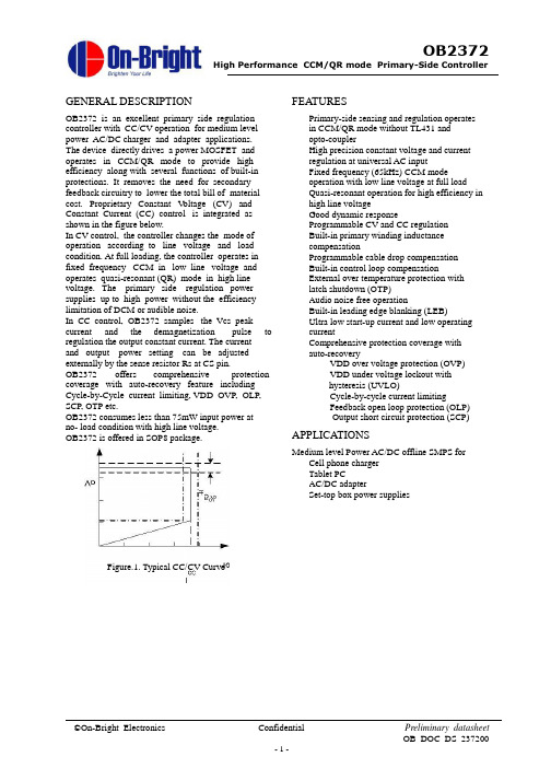
GENERAL DESCRIPTION FEATURESOB2372 is an excellent primary side regulation controller with CC/CV operation for medium level power AC/DC charger and adapter applications. The device directly drives a power MOSFET and operates in CCM/QR mode to provide high efficiency along with several functions of built-in protections. It removes the need for secondary feedback circuitry to lower the total bill of material cost. Proprietary Constant V oltage (CV) and Constant Current (CC) control is integrated as shown in the figure below.In CV control, the controller changes the mode of operation according to line voltage and load condition. At full loading, the controller operates in fixed frequency CCM in low line voltage and operates quasi-resonant (QR) mode in high line voltage. The primary side regulation power supplies up to high power without the efficiency limitation of DCM or audible noise. Primary-side sensing and regulation operates in CCM/QR mode without TL431 andopto-couplerHigh precision constant voltage and currentregulation at universal AC inputFixed frequency (65kHz) CCM modeoperation with low line voltage at full loadQuasi-resonant operation for high efficiency in high line voltageGood dynamic responseProgrammable CV and CC regulationBuilt-in primary winding inductancecompensationProgrammable cable drop compensationBuilt-in control loop compensationExternal over temperature protection withlatch shutdown (OTP)Audio noise free operationBuilt-in leading edge blanking (LEB)Ultra low start-up current and low operatingcurrentIn CC control, OB2372 samples the Vcs peak current and the demagnetization pulse toregulation the output constant current. The current and output power setting can be adjusted externally by the sense resistor Rs at CS pin. Comprehensive protection coverage with auto-recoveryVDD over voltage protection (OVP)VDD under voltage lockout withhysteresis (UVLO)Cycle-by-cycle current limitingFeedback open loop protection (OLP)Output short circuit protection (SCP)OB2372 offers comprehensive protectioncoverage with auto-recovery feature includingCycle-by-Cycle current limiting, VDD OVP, OLP,SCP, OTP etc.OB2372 consumes less than 75mW input power atno- load condition with high line voltage.OB2372 is offered in SOP8 package. APPLICATIONSMedium level Power AC/DC offline SMPS forCell phone charger Tablet PCAC/DC adapterSet-top box power suppliesFigure.1. Typical CC/CV CurveTYPICAL APPLICATIONGENERAL INFORMATIONAbsolute Maximum Ratings Parameter VDD V oltage FB Input V oltage RT Input V oltage CS Input V oltage GATE Input V oltage Min/Max Operating JunctionTemperature T J Value Pin ConfigurationThe pin map is shown as below for SOP8.-0.3 to 30V -0.3 to 7V -0.3 to 7V -0.3 to 7V -0.3 to 24V FB RT 1 2 8 7 6 5VDD GND -40 to 150℃-55 to 150℃ 260℃ Min/Max Storage NC 3 4GATE CSTemperature T stgLead Temperature COMP(Soldering, 10secs)Note: Stresses beyond those listed under “absolute maximumratings” may cause permanent damage to the device. These are stress ratings only, functional operation of the device at these or any other conditions beyond those indicated under “recommended operating conditions” is not implied. Exposure to absolute maximum-rated conditions for extended periods may affect device reliability.Ordering Information Part Number OB2372CP Description SOP8, Pb-free in TubeSOP8, Pb-free in T&R OB2372CPARecommended Operating ConditionSymbol VDD Parameter VDD Supply V oltage Operating TemperatureRange 9 to 22VPackage Dissipation RatingPackage R θJA (℃/W) AmbientT A -20 to 85 ℃SOP8 150Marking InformationTERMINAL ASSIGNMENTSPin Num Pin NameI/O DescriptionThe voltage feedback from auxiliary winding. Connected to resistor divider from auxiliary winding reflecting output voltage.1 FB I IConnected through a NTC resistor to ground for over temperature protection.2 3 4 RT NC COMP I/O I Connected through Cap to ground for CC loop compensation. 5 CS Current sense input. Connect a sense resistor from this pin to ground. 6 7 8GATE GND VDDO P PGate driver of power MOSFET. Ground Power SupplyBLOCK DIAGRAMELECTRICAL CHARACTERISTICS(TA = 25℃, VDD=18V , if not otherwise noted) Symbol Parameter Test Conditions MinTyp. Max Unit Supply V oltage (VDD) Section I start-up I static Start up current VDD=UVLO_OFF-1V5 15 uA Static current1.2 1.8 15.6 7.9 25 1.82.5 16.6 8.6 26.6 6.3 60mA mA V Iop_sOperating currentFB=1V , 1nF gate load.UVLO(OFF) UVLO(ON) VDD_OVP Vlatch_off Ilatch_offVDD under voltage lockout exit VDD under voltage lockout enter VDD over voltage protection Latch release vdd voltage Latch release Icc current14.6 7.2 V 23.5 4.3 V 5.3 42 V 30uA Current Sense Input Section TLEB LEB time 300 100 750 150ns TD_OC OCP propagation delayMaximum over current threshold Minimum CS threshold ns Vth_ocp_maxVcs_mini mV mVFB Input Section Reference voltage for feedback thresholdVref_fb 2.475 2.500 2.525 V V_OVP Output Over voltage threshold Minimum Toff2.953.05 2.0 3.15V Tpause_min us Maximum cable compensation currentIcomp_cable48 uA CC Loop Section Vref_cc CC loop reference19060200 16210 70 mV usCC loopintegratorGmtransconductance Timer Section Fs_ccm CV CCM switch frequency Maximum duty 65 68 KHz % Duty_max 65K jitteringfixed switchfrequencyFs_ccm_jitter +/- 4%Fs_max FminCV QR maximum frequency Minimum switch frequency90 KHz Hz 250 10300 350 13Gate Driver Section V_clamp Output clamp voltage level 11.5 150 50 V Tr TfOutput rising time Output falling timeCL=1nF CL=1nFns nsOutput Over V oltage Protection V_OVP Output Over voltage threshold 2.95 3.05 3.15 V External OTP Section I_otp RT pin source currentOver temperature trigger voltage 47.5 1.050 52.51.1uA VV_otp1.05CHARACTERIZATION PLOTSCV mode OperationOB2372 is designed to produce good CC/CV OPERATION DESCRIPTIONcontrol characteristic as shown in the Figure. 1. In charger applications, a discharged battery charging starts in the CC portion of the curve until it is nearly full charged and smoothly switches to operate in CV portion of the curve. The CC portion provides output current limiting. In CV operation, the output voltage is regulated through the primary side control. In CC operation mode, OB2372 will regulate the output current constant regardless of the output voltage drop.OB2372 is an excellent integrated multi-mode (see Figure 2) PWM controller optimized for off-line middle power AC/DC applications. It operates in continuous conduction mode (CCM) and quasi-resonant mode (QR) to provide high efficiency with primary side sensing and regulation thus provide cost effective solution for energy efficient power supplies.At full loading, the IC operates in fixed frequency (65KHz) CCM mode in the low line input voltage and it operates in QR mode in high line input voltage. In this way, high efficiency in the universal input range at full loading can be achieved.At normal load condition, it operates in QR mode. Principle of OperationWith OB2372 proprietary CC/CV control, system can be designed in CCM/DCM mode for flyback system (Refer to the Typical Application Diagram in page1).To minimize switching loss, the maximum switching frequency in QR mode is internally limited to 90 KHz (typical). When the load goes low, it operates in PFM mode with valley switching for high power conversion efficiency. When the load is very small, the IC switch frequency can be reduced to 300Hz to minimize the standby power loss. As a result, high conversion efficiency can be achieved in the whole loading range.In the flyback converter, the output voltage can be sensed via the auxiliary winding. During MOSFET turn-on time, the load current is supplied from the output filter capacitor and the current in the primary winding ramps up. When MOSFET turns off, the energy stored in the primary winding is transferred to the secondary side and the current in the secondary winding isI S NN P I P(1)S The auxiliary winding voltage reflects the output voltage as shown in Figure.3 and it is given byV AUX N AUX (V O V )(2)N SWhere V indicates the voltage drop of the output Diode.Figure 2 Multi-mode operation diagramProprietary built-in CV and CC control can achieve high precision CC/CV control meeting most charger application requirements.Startup Current and Start up ControlStartup current of OB2372 is designed to be very low so that VDD could be charged up above UVLO threshold level and device starts up quickly. A large value startup resistor can therefore be used to minimize the power loss yet achieve a reliable startup in application.Figure.3. Auxiliary winding voltage waveform Via a resistor divider connected between the auxiliary winding and FB (pin 1), the auxiliary winding voltage is sampled at the middle of the de-magnetization and it is hold until the next sampling. The sampled voltage is compared with reference voltage Vref (typical 2.5V) and the difference is amplified. The error amplifier output reflects the load condition and controls theOperating CurrentThe Operating current of OB2372 is as low as 1.8mA (typical). Good efficiency and less than 100mW standby power is achieved with the low operating current.switching off time to regulate the output voltage, maximum compensation isthus constant output voltage can be achieved. CC mode operationOB2372 sample the CS peak and the transformer core demagnetization period to regulate to output current. The primary CS peak is adaptively controlled according to the voltage of COMP pin.V48 6200 10 6100% 11.9%2.5V o I o N I pk T (3)demag T sWhere Ipk indicates the peak current of primary winding, Tdemag is the transformer core demagnetization period, and Ts the switch period. Refer to the equation 3, regulating the Ipk can achieve the constant output current. The constant output current is not related to the primary winding inductance and switch frequency.Figure 5 Diagram for cable drop compensation Current Sensing and Leading Edge BlankingCycle-by-Cycle current limiting is offered in OB2372. The switch current is detected by a sense resistor into the CS pin. An internal leading edge blanking circuit chops off the sensed voltage spike at initial power MOSFET on state so that the external RC filtering on sense input is no longer needed.Adjustable CC point and Output PowerIn OB2372, the CC point and maximum output power can be externally adjusted by external current sense resistor Rs at CS pin as illustrated in the typical application diagram. The larger Rs, the smaller CC point is, and the smaller output power becomes, and vice versa as shown in Figure.4.Gate DriverThe GATE pin is connected to the gate of an external power switch. An internal 11.5V (typical) clamp is added for MOSFET gate protection at high VDD voltage. When VDD voltage drops below UVLO(ON), the GA TE pin is internally pull low to maintain the off state.Over Temperature Protection with latch shutdownA NTC resistor in series with a regular resistor should be connected between RT and GND for temperature sensing and protection. NTC resistor Figure.4. Adjustable output power by changing Rs value becomes lower when the ambient temperature rises. With the fixed internal 50uA current source flowing through the resistors, the voltage at RT pin becomes lower at high temperature. The internal OTP circuit is triggered and shuts down the MOSFET when the sensed input voltage is lower than 1.05V . OTP is a latched shutdown.Programmable Cable Drop CompensationIn OB2372, cable drop compensation is implemented to achieve good load regulation (see Figure 5). An offset voltage is generated at FB pin by an internal current flowing into the resister divider. The current is proportional to the switching off time, as a result, it is inversely proportional to the output load current, and the drop due to the cable loss can be compensated. As the load current decreases from full-load to no-load, the offset voltage at FB will increase. It can also be programmed by adjusting the resistance of the divider to compensate the drop for various cable lines used.Protection ControlGood power supply system reliability is achieved with its rich protection features including Cycle-by-Cycle current limiting, Output over voltage protection, VDD over voltage protection, short circuit protection, Under V oltage Lockout on VDD.VDD is supplied by transformer auxiliary winding output after startup. The output of OB2372 is shut down when VDD drops below UVLO (ON) and the The percentage of maximum compensation isI comp _ cable R 1 // R 2 10 6V100% V o V 2.5power converter enters power on start-up is load compensation voltage and V o isoutput voltage;sequence thereafter.For example: R1//R2=6.2Kohm, the percentage ofPACKAGE MECHANICAL DATADimensions In Millimeters Dimensions In Inches SymbolMin Max Min MaxA A1 A2 b c D E 1.3500.0501.2500.3100.1004.7003.8005.8001.7500.2501.6500.5100.2505.1504.0006.2000.0530.0020.0490.0120.0040.1850.1500.2280.0690.0100.0650.0200.0100.2030.1570.244E1e 1.270 (BSC) 0.050 (BSC)L θ0.4000º1.2708º0.0160º0.0508ºOB2372High Performance CCM/QR mode Primary-Side ControllerIMPORTANT NOTICERIGHT TO MAKE CHANGESOn-Bright Electronics Corp. reserves the right to make corrections, modifications, enhancements, improvements and other changes to its products and services at any time and to discontinue any productor service without notice. Customers should obtain the latest relevant information before placing ordersand should verify that such information is current and complete.WARRANTY INFORMATIONOn-Bright Electronics Corp. warrants performance of its hardware products to the specifications applicableat the time of sale in accordance with its standard warranty. Testing and other quality control techniquesare used to the extent it deems necessary to support this warranty. Except where mandated by government requirements, testing of all parameters of each product is not necessarily performed.On-Bright Electronics Corp. assumes no liability for application assistance or customer product design. Customers are responsible for their products and applications using On-Bright’s components, data sheetand application notes. To minimize the risks associated with customer products and applications, customers should provide adequate design and operating safeguards.LIFE SUPPORTOn-Bright Electronics Corp.’s products are not designed to be used as components in devices intended tosupport or sustain human life. On-bright Electronics Corp. will not be held liable for any damages or claims resulting from the use of its products in medical applications.MILITARYOn-Bright Electronics Corp.’s products are not designed for use in military applications. On-Bright Electronics Corp. will not be held liable for any damages or claims resulting from the use of its products in military applications.©On-Bright Electronics Confidential Preliminary datasheetOB_DOC_DS_237200- 11 -。
TEA1781T资料
TEA1781T; TEA1782TGreenChip PC secondary control ICsRev. 01 — 13 February 2009Preliminary data sheet1.General descriptionThe TEA1781T and TEA1782T are designed to cooperate with the TEA1771T primaryside controller in a unique converter topology based on the active clamp forwardconverter. On the secondary side the output voltages are regulated via bidirectionalswitches. A typical application area of this converter is a power supply for a desktop PC.The TEA1781T and TEA1782T are secondary control ICs and regulate each outputvoltage independently of the primary duty cycle and other secondary output voltages.Because of these separated regulations, the system does not show any cross regulationand makes the design of the transformer easier.As each output can also be completely turned off, the system allows for an integratedstandby supply.T o maximize the efficiency in Standby mode,the duty cycle and operatingfrequency are minimized in Standby mode.The TEA1781T and TEA1782T have integrated drivers and individual output voltageregulators. In this way the 3.3 V, 5 V, 12 V and 5V standby outputs of a typical PC powersupply are regulated separately giving accurate output voltages and fast transientresponse.All requirements according to the Intel ATX specification (V 2.0) are integrated, such assoft start, a PS_ON# connection, a PwrOK signal and all required protections likeOverCurrent Protection (OCP) and OverVoltage Protection (OVP). These voltage andcurrent levels are monitored at each output separately. The system also has anOverT emperature Protection (OTP) function.The system fulfills the current and proposed efficiency standards such as 80+ gold,energy star and blue angel.The TEA1781T and TEA1782T are implemented in a high voltage (ABCD)Silicon On Insulator (SOI) process.2.FeaturesI Designed for A TX PC power suppliesI Integrated standby supplyI Enhanced efficiency in Standby modeI No cross regulationI Accurate output voltage regulationI Fast transient responseI Integrated soft start for all output voltagesI Flexible transformer design without the need of a post regulatorI Overvoltage protectionI Overcurrent protectionI Overtemperature protectionI System failure detectionI Soft (re)startI Low external component count3.ApplicationsI PC desktop power supply4.Ordering informationTable 1.Ordering informationType number PackageName Description Version TEA1781T SO28Plastic small outline package; 28 leads; body width7.5mm SOT136-1 TEA1782T SO28Plastic small outline package; 28 leads; body width7.5mm SOT136-15.Block diagramFig 1.TEA1781T block diagramPGOODstartV ref(3V3)startV ref(5V)t dQ RSV ref(5V)V ovp(VOUT_5V)V uvp(VOUT_5V)V ref(OCP)I ocpI-control 5 VControl 3.3 V V ref(3V3)I-control 3.3 VIIProtection 5 VI O > I ocpV ovp(VOUT_3V3)IOI OProtection 3.3 VI O > I ocpVDDSoft StartQ RSV uvp(VOUT_3V3)VDDPull-downStart-upEnable Temperature protectionPowerGoodPowerOKV trip(ENABLE)V otpControl 5 V Drive SRDrive 5 VDrive 3.3 VF S RW N D _S E C _2G S RG S B _5VD F _5VF S B _5VP G N D _5VG S F _5VC S _5V V O U T _5VO C PG S B _3V 3D F _3V 3F S B _3V 3PG N D _3V 3G S F _3V 3C S _3V 3V O U T _3V 3V S E N S E _5V VSENSE_3V3VST ARTUPVDD GND GNDE N A B L EV N T CP G O O D V/I014aaa181P W R O K V/IV/I 28236687126271112242023251716211913141541822109I ENABLEV reg(VDD)V tripI pdI pd6.Pinning information6.1PinningFig 2.TEA1782T block diagramt dQ RSV ovp(VOUT_STB)Protection standbyI VOUT_STB > I OCP_STB VDDVDDControl 12 VDrive SRDrive 12 VDrive standbyDrive 3.3 VFSR WND_SEC_1GSRGSB_12V DF_12VFSB_12VPGND_12VGSF_12V CS_STBVOUT_STB 014aaa182Pull-downVref(12V)Control 12 VI V/IV/IIV ref(OCP)I OCP_STBOCP_STBI VOUT_STBV ovp(VOUT_12V1)V ref(OCP)I OCP_12VI VOUT_12V Protection 12 VControl standbyV uvp(VOUT_12V1)V ref(stb)I-control standbyPower-GoodI V/I ST ARTUP V ENABLE = 4 VPROT/STDB V ENABLE = 4 VNORMAL V ENABLE = 11 VSYSTEM REST ARTsystem failure detectionV VDD > V startup(VDD)V VDD > V startup(VDD)V VDD < V stop(VDD)V ENABLEPS_OFFI ENABLE > I prot(ENABLE)+ EN_NM + PS_OFF+ PROT_12V + UVP_STBPROT_STBPROT_12V UVP_STBV uvp(VOUT_STB)Q RSDOWNV/IUPsystem restart normalV EN_NMEN_NMstartV ref(12V)start V ref(stb)Soft StartStartup Opto controlV startup(VDD)EN_NM ENABLE PS_OFF VDD GND GNDVDDOPTOPGOODCS_12V VOUT_12V1VOUT_12V2OCP_12VGSB_STBDF_STBFSB_STB PGND_STBGSF_STBIEnable NMDigital control I VOUT_12V2I pdV trip12 V OCP detectionFig 3.TEA1781T pin configuration Fig 4.TEA1782T pin configurationFSR GSR WND_SEC_2FSB_3V3GSB_3V3DF_3V3PGOOD CS_3V3VOUT_3V3VSENSE_3V3PWROK GSF_5V PGND_3V3GND GSF_3V3GND VDDFSB_5V GSB_5V DF_5V VSTARTUPOCP PGND_5V CS_5V VOUT_5V VSENSE_5VVNTCENABLE TEA1781T 014aaa18312345678910111213141615181720192221242326252827FSR GSR WND_SEC_1FSB_STB GSB_STB DF_STB OCP_STB CS_STB VOUT_STB OPTO PGOOD GSF_12V PGND_STB GND GSF_STB GND VDDFSB_12V GSB_12V DF_12V OCP_12V CS_12V PGND_12V VOUT_12V1VOUT_12V2EN_NM PS_OFFENABLE TEA1782T014aaa184123456789101112131416151817201922212423262528276.2Pin descriptionTable 2.TEA1781T pin descriptionSymbol Pin DescriptionFSB_5V1floating supply switch SB_5VGSB_5V2gate driver switch SB_5VDF_5V3drain voltage of switch SF_5VVST ARTUP4start-up voltage connected to rectified secondary winding voltage OCP5overcurrent protectionCS_5V6current sense 5 V outputVOUT_5V7output voltage 5 V outputVSENSE_5V8sense voltage 5 V outputVNTC9NTC voltageENABLE10enabling Normal modePGND_5V11power ground 5 V outputGSF_5V12gate driver switch SF_5VGND13groundGND14groundVDD15supply voltageGSF_3V316gate driver switch SF_3V3PGND_3V317power ground 3V3 outputPWROK18power OKVSENSE_3V319sense voltage 3.3 V outputVOUT_3V320output voltage 3.3 V outputCS_3V321current sense 5 V outputPGOOD22PowerGood (delay setting for power OK)DF_3V323drain voltage of switch SF_3V3GSB_3V324gate driver switch SB_3V3FSB_3V325gate driver switch SB_3V3WND_SEC_226secondary transformer 3.3 V / 5 V winding voltageGSR27gate driver switch SR (3.3 V / 5 V)FSR28floating supply switch SR (3.3 V / 5 V)Table 3.TEA1782T Pin descriptionSymbol Pin DescriptionFSB_12V1floating supply switch SB_12VGSB_12V2gate driver switch SB_12VDF_12V3drain voltage of switch SF_12VOCP_12V4overcurrent protection 12 V outputCS_12V5current sense 12 V outputVOUT_12V16output voltage 12 V1 outputVOUT_12V27output voltage 12 V2 outputEN_NM8enable Normal modeTable 3.TEA1782T Pin description …continuedSymbol Pin DescriptionPS_OFF9power supply off (via delay network connected to PS_ON#)ENABLE10enabling Normal modePGND_12V11power ground 12 V outputGSF_12V12gate driver switch SF_12VGND13groundGND14groundVDD15supply voltageGSF_STB16gate driver switch SF_stbPGND_STB17power ground standby outputPGOOD18PowerGood (delay setting for power OK)OPTO19opto couplerVOUT_STB20output voltage standby outputCS_STB21current sense standby outputOCP_STB22overcurrent protection standby outputDF_STB23drain voltage of switch SF_stbGSB_STB24gate driver switch SB_stbFSB_STB25gate driver switch SB_stbWND_SEC_126secondary transformer 12 V / standby winding voltageGSR27gate driver switch SR (12 V)FSR28floating supply switch SR (12 V)7.Functional description7.1IntroductionA PC power supply has to supply a number of different supply voltages: 12 V, 5 V, 3.3V,−12V and 5V standby. To achieve the required output voltage accuracy, the systems oftoday require dissipative post regulations.Because the system must be able to switch off the main supplies(12V,5V,3.3V,−12V)in Standby mode but keep the 5 V standby in operation, a separate standby supply is stillcommon practice.With the GreenChip PC chip set (TEA1771T, TEA1781T, TEA1782T) a systemconfiguration is introduced that integrates the post regulation and combines the main andstandby converter into a single system.This high level of integration reduces the total costof the system.Because the output voltages are regulated separately, it makes the design of theconverter easier as none of the output voltages is directly related to the number of turnson the transformer.One of the main differences of this topology compared to commonly used solutions is theuse of switches instead of Schottky diodes, although the rectifying switch is a so-calledbidirectional switch. This switch is built up by two standard FETs in anti-series.The freewheel switch behaves like an ideal diode so the setup runs in a discontinuous mode at low loads. Negative currents are avoided by the control ICs through this switch.Replacement of the rectifying Schottky diode by two switches in anti-series allows:•Integration of the 5 V standby supply, because in Standby mode the main secondaryoutputs can be switched off.The supply voltages can be individually and more accurately regulated, eliminating ubiquitous post regulators.•As the output voltages is now regulated by the secondary switches, the duty cycle ofthe primary control switch can be kept constant, preventing ringing at the primary reset voltage.A lower reset voltage results in lower required breakdown voltages of all applied FETs, both primary and secondary. This reduces costs.•The use of Zero Voltage Switching (ZVS) at the primary side to fulfill the requiredstandby efficiency.To fulfill the A TX12V specification on standby efficiency requirements, the system has a Standby mode in which the frequency, duty cycle and supply currents are reduced.The TEA1781T and TEA1782T are secondary control ICs. Together with the TEA1771T primary controller they form a unique system that fulfills the 80+ gold requirements at minimum costs, eliminating any cross regulation and maximizing standby efficiency.7.2SupplyWhen the voltage on the primary side from the rectified input mains reaches its starting value, the primary side starts up and switches the primary main switch. From thatmoment, the secondary rectified transformer voltage at V startup , see Figure 5, is a ratio of the input voltage.Fig 5.Start-up sequence TEA1771T014aaa185Start-upTEA1781TEA1782VSTARTUP VDDV startup(VDD)VDDUVLOStart-upV VOUT_STB12 VThe VDD capacitor is charged and regulated to the V reg(VDD)level via a linear regulator in the TEA1781T . This VDD voltage is the supply voltage for both secondary ICs.Once the VDD voltage reaches the V startup(VDD) level, measured in the TEA1782T, the 5V standby is started up via a so-called soft start.This implies that during a certain time,t start(soft), the output voltage slowly ramps up from zero to the required value. Once the system is started up, the VDD voltage is taken over by an auxiliary winding of the 5V standby output, as shown in Figure 5. This ensures an efficient 12 V VDD voltage during standby and normal operation.As the secondary ICs are supplied via the TEA1781T and measured in the TEA1782T,both ICs are disabled in case of an open connection in the supply chain.If the VDD voltage drops below its V stop(VDD)level,the system disables all output voltages by actively turning off all switches. This avoids undefined conditions resulting from charged gate capacitances.7.3Mode of operationAfter the system has started up,the TEA1782T defines the mode of operation.It features four operation modes: Start-up mode, Protection/Standby mode, Normal mode and System restart mode, as depicted in Figure 6.When the VDD voltage is below its stop level, the TEA1782T enters the Start-up mode and the TEA1781T charges the VDD capacitors to V reg(VDD) via the start-up pin. When it has charged the VDD capacitor above V startup(VDD), the TEA1782T jumps intoProtection/Standby mode and the 5V standby output slowly rises from zero to its required value.When the PS_OFF signal becomes active low, the system switches to Normal mode enabling the main outputs (3.3 V , 5 V , 12 V and −12 V). The 12 V (and −12 V) output is regulated by the TEA1782T itself, whereas the 3.3 V and 5 V output are regulated by the TEA1781T . The TEA1781T activates the 3.3 V and 5 V outputs via the ENABLE signal.Fig 6.State diagram TEA1771TI ENABLE > I prot(ENABLE)+ EN_NM + PS_OFF+ PROT_12V + UVP_STB ST ARTUP V ENABLE = 4 VPROT/STDB V ENABLE = 4 VNORMAL V ENABLE = 11 VSYSTEM RESTARTsystem failure detectionV VDD > V startup(VDD)V VDD < V stop(VDD)PS_OFF Digital control014aaa186At any failure condition or as soon as the PS_OFF signal is high, the system switches to Protection / Standby mode. When a failure, such as a shorted or overloaded output, is detected, the system enters the Protection mode, disabling the main output circuits but leaving the standby output in operation.However,when,for example,a secondary FET is shorted, the system enters the System restart mode and switches off the primary side.When VDD is discharged below its minimum level, V stop(VDD), the IC enters the Start-up mode and all switches are disabled.When the system is in Protection / Standby mode, the systems lowers its duty cycle and operating frequency to optimize the system’s efficiency.7.4Enable Normal modeIn Standby mode,an optional PFC may be switched off.When switched to Normal mode,the system has a programmable delay before the main outputs (3.3 V , 5 V and 12 V) are switched on. During this delay the PFC can be activated.An extra safety feature has been built in when enabling Normal mode. If the input voltage is too low, which can occur when the PFC fails, the system stays in Standby mode.The input voltage is measured on a rectified secondary voltage, reflecting the input voltage; see Figure 7.In addition to a minimum input voltage, a delay can also be made to assure a proper start-up of the PFC before the system switches to Normal mode. A circuit according to Figure 8 must be built between the PS_ON# signal from the motherboard and the PS_OFF pin of the TEA1782T.Fig 7.Enable Normal mode assures a proper start-up of the forward converterNp / NsV WND_SEC_2Enable NM Digital control 1.25 VEN_NM014aaa1877.5Soft startWhen the TEA1782T enters the Protection/Standby mode after start-up, the 5V standby output is started up via a soft start. The main output voltages, 3.3 V , 5 V , 12 V and −12 V are started up via a soft start when the TEA1782T enters the Normal mode. A soft start implies that the outputs will rise gradually and simultaneously from zero to their required value during a defined period (≈ 15 ms).When PS_OFF is turned low,the main outputs of the TEA178x chip set ensure that power sequencing is applied according to the ATX12V specification of Intel,i.e.,the 12V and 5V outputs must be equal to, or greater than, the 3.3 V output during power-up and normal operation.7.6EnableThe TEA1782T is the master of the system. The required duty cycle is communicated to the primary controller TEA1771T via the opto coupler. The TEA1782T communicates to the TEA1781T via the enable signal, see Figure 9, if the main outputs are enabled or disabled. If the system is in Normal mode, the voltage of the enable signal exceeds the trip level, V trip(ENABLE), enabling all outputs. Otherwise the main outputs are disabled.Fig 8.Enable Normal mode assures a proper start-up of the PFCD1014aaa188R1D2R2C1PS_ON#5 V standbyPS_OFFTEA1782I ENABLE > I prot(ENABLE)+ EN_NM + PS_OFF+ PROT_12V + UVP_STB ST ARTUP V ENABLE = 4 VPROT/STDB V ENABLE = 4 VNORMAL V ENABLE = 11 VSYSTEM RESTARTsystem failure detectionV VDD > V startup(VDD)V VDD < V stop(VDD)PS_OFF Digital controlFig 9.The ENABLE signal is for communicating between the secondary control ICs014aaa189V trip(ENABLE)temp.prot protection 5 VV ENABLETEA1782TEA17813.3 V / 5 V outputs are enabledENABLEprotection 3.3 VI ENABLE > I prot(ENABLE)+ EN_NM + PS_OFF+ PROT_12V + UVP_STB STARTUP V ENABLE = 4 VPROT/STDB V ENABLE = 4 VNORMAL V ENABLE = 11 VSYSTEM RESTARTsystem failure detectionV VDD > V startup(VDD)V VDD < V stop(VDD)PS_OFF Digital control I ENABLE7.7Output driversFigure 10 shows a part of the secondary side output circuitry and the applied gate drive system.The freewheel switch SF is turned on and off between the VDD voltage (12V)and ground level as the source of SF is connected to ground.The source of switch SB varies between zero (actually a small negative voltage when the SF or its back gate diode is conducting)and the maximum secondary transformer voltage. Therefore the driver of SB requires a bootstrap circuit.When V DF_x (V DF_3V3,V DF_5V ,or V DF_12V )is (about)zero,the FSB capacitor is charged to the VDD level.Switch SB can then be turned on via this charged capacitor,as it ensures a VDD voltage with respect to DF_x (pins DF_3V3, DF_5V , or DF_12V). As this capacitor will be discharged when charging the gate source capacitance of SB, the driving voltage will be slightly less than the VDD voltage.The source of the rectifying switch SR is connected to the transformer, which can be positive or negative. Therefore the FSR capacitor is charged via a boost circuit with a special voltage source that is about 12V higher than the secondary transformer voltage at the appropriate time.As the source of the rectifying switch SR is connected to the transformer, which can be either negative or positive, the TEA1781T and TEA1782T are developed in a special process (ABCD - SOI) which is capable of handling these (high) negative and positive voltages.(1)WND_SEC_x: The “x” stands for either 1 or 2(2)FSR_x,, GSR_x, GSB_x, DF_x, FSB_x:The “x” for these pins and symbols stands for either 3V3, 5V or 12V (3)VOUT_x: The “x” stands for either 3V3, 5V , 12V1 or 12V2.Fig 10.Output driver circuit014aaa190VDDDriveF S R _xW N D _S E C _xG S R _xG S B _xD F _xV WND_SEC_x + 12 VV VOUT_xDF_xSFSR V WND_SEC_xSB F S B _xV INDC / N 0V WND_SEC_xV INDC / NV FSB_x V DF_x7.8Output voltage regulationThe output voltage is regulated to the required voltage level via a current mode control loop.When the secondary side transformer voltage is negative,switch SB is turned off to avoid negative currents,see Figure 11.Once the secondary side transformer voltage is positive and the output current in the secondary coil has dropped below a certain value,switch SB is turned on again.This value is proportional to the difference between the output voltage and the reference voltage,increased with a ramp voltage.This type of regulation is called current mode control. A ramp voltage is required to stabilize the control loop for duty cycles smaller than 0.5 and is called slope compensation.The output current is measured using the output inductor series resistance. When theparallel RC network is the voltage across the parallel capacitor equals thevoltage across the inductors resistance. L and R L represent the inductance and the resistance value of the output inductor.(1)WND_SEC_x: The “x” stands for either 1 or 2(2)GSB_x, DF_x, FSB_x, GSF_x, CS_x:The “x” for these pins and symbols stands for either 3V3, 5V or 12V (3)VOUT_x: The “x” stands for either 3V3, 5V , 12V1 or 12V2.Fig 11.Output voltage regulation014aaa191VDD DriveControlG S B _xD F _xV VOUT_xSFSR V WND_SEC_xSB F S B _xQ RS V refI-controlI V/IIResetSB LRCG S F _xV O U T _xclosed closed"0""1"openopen V INDC / N −V rst / N 0V WND_SEC_x ResetSBSBSFC S _xR C LR L -----=⋅7.9PowerOKThe PowerOK signal is active HIGH when the main output voltages (12V , 5V and 3.3V)are within their regulation limits.Figure 12 shows the corresponding block diagram.The PGOOD output is pulled down by the TEA1781T when either the 5V or 3.3V is below its lower limit, or by the TEA1782T when the 12 V is below its lower limit. When all main outputs are above their minimum value, the PGOOD signal slowly rises from zero to the VDD level.Once the PGOOD signal exceeds V PGOOD ,the PWROK signal becomes active high.A delay can be set between the output voltages reaching their end value and the PWROK signal being active high via an RC network connected to the PGOOD pins.7.10Pull-down main outputsAccording to the Intel A TX specification,the main outputs (3.3V ,5V and 12V)must be at ground level in Standby mode.Therefore,these outputs are pulled low when the system is in Standby mode.The pull-down transistors for the 3.3 V and 5 V outputs are integrated in the TEA1781T,whereas the pull-down transistor for the 12 V is integrated in the TEA1782T.7.11OPTO controlThe TEA1782T defines the mode of operation of the system. It communicates with the TEA1781T via the ENABLE pin and with the TEA1771T primary controller via the opto coupler connected to the OPTO control block. Depending on the mode of operation, the current to the opto coupler has the following values:Fig 12.PowerOK circuit diagramPowerGood014aaa192V uvp Protection 5 VV uvpProtection 3.3 VV PGOODPowerOKPowerGoodVOUT_5V VOUT_3V3V uvpProtection 12 VVOUT_12VPWROKVDDPGOOD PGOOD PWROK 5 V standby TEA1781TEA1782In Standby mode, a higher I OPTO current implies a higher duty cycle / frequency of the system. In Normal mode, the systems duty cycle/frequency is defined by the primary controller being related to the inverse of the input voltage. The OPTO control block diagram is given in Figure 13.At system start-up, the secondary controllers are supplied via a rectified secondarywinding voltage.Therefore the secondary controllers are started up after the primary side has started up.As the voltage at the OPTO pin is zero when the secondary controllers are not yet supplied, the primary side starts up at the minimum duty cycle/frequency. Once thesecondary side has started,it increases the operating duty cycle/frequency of the system depending on the standby load and mode of operation.When the system is in Normal mode, switch S3 is closed and the opto coupler current is increased to I OPTO (Normal mode). In this mode, the primary duty cycle is defined by the primary controller TEA1771T and is related to the inverse of the input voltage.When the secondary protection mode fails, switch S4 is closed and a maximum current flows through the opto coupler. This high current triggers the primary controller into Protection mode, switching off the primary main switch. A safe restart of the system will follow.This implies that the system will start up again after all the supply voltages,primary and secondary, are below their UVLO levels resulting in a total reset of the system.In Standby mode, the system minimizes the duty cycle of the primary control switch to reduce the magnetic losses in the transformer to a minimum. As the primary duty cycle has to be at least equal to the secondary duty cycle, the system will equalize both duty cycles in Standby mode. This is regulated in the opto control block.Table 4.OPTO control modesMode of operation I OPTOStandby mode 0 mA to ≈3.5mA Normal mode ≈3.5mA System restart≈30mAFig 13.TEA1782T OPTO control diagram014aaa193DOWNV/IUP OPTO controlPVCCoffS1S3S4S2INormal modeOPTOThe opto control compares the primary and secondary standby duty cycle and defines if the primary duty cycle has to be changed, see Figure 14.The primary duty cycle is derived from the secondary transformer voltage. If V WND_SEC_1is above a certain positive level before the switch SB is turned on, a down pulse is generated. An up pulse is generated when V WND_SEC_1 is high after SB is turned on.The current into the opto coupler is regulated until it reaches a stable value via the down pulse and up pulse. Through the opto coupler, the primary duty cycle and frequencyeventually stabilize to provide the duty cycle required by the secondary standby converter.7.12Protections7.12.1GeneralAll outputs have an OVP and an OCP function.The OVP and OCP functions have a delay of t d(prot), which is typically 18µs.If the output voltage or the output current on one of the main outputs (3.3V ,5V ,12V1,or 12 V2) exceeds their upper limit, the system will enter Protection mode. In this mode all main outputs are switched off by switching off all corresponding secondary switches. The system will enter the Normal mode again after toggling the PS_ON# signal or after a mains interruption.A 12V OVP /OCP is detected in the TEA1782T.When detecting a 12V OVP or OCP ,the pin ENABLE is pulled down and as a result both the TEA1782T and the TEA1781T will disable the main outputs. The 5 V standby output remains on.A 3.3 V or 5 V OVP or OCP is detected in the TEA1781T and communicated to theTEA1782 via the pin ENABLE. As a result the TEA1782T will pull down the pin ENABLE,disabling all main outputs.Fig 14.TEA1782T OPTO control duty cycles014aaa194closed open V INDC / N−V rst / N V WND_SEC_1SBdownupI OPTOS1primairy main switchclosedopen"1""0""1""0"decreasing prim δincreasing prim δWhen the5V standby voltage/current exceeds its upper limit the output will be switched off. It will be turned on again at the next cycle as soon as the output voltage/current level drops below the upper limit.7.12.2Undervoltage protectionWhen undervoltage is detected on one of the main outputs (3.3 V, 5 V, 12 V) the pinPGOOD is pulled low which again pulls the PWROK signal low.When undervoltage on the 5 V standby output is detected, the system switches toStandby mode and returns back to Normal mode once the 5 V standby is above itsminimum level.7.12.3Overvoltage protectionAs stated previously, all outputs have an OVP function. However, the 12 V1 and 12 V2have one OVP function. It is assumed that the 12 V2 is directly coupled to the 12 V1voltage and therefore these voltages are about equal.All OVP levels are integrated and cannot be set externally.7.12.4Overcurrent protectionThe OCP levels can be set externally. The maximum output current of the 12 V1 and 12V2 are supposed to be about equal, therefore have the same OCP setting.Figure15gives the 12 V OCP block diagram.The total output current (equal to I out_12V1 + I out_12V2) is measured via an RC network across the output inductor, using the series resistance of the output inductor. The 12V2output current is measured using a series resistance.Subtracting these two then gives the 12V1 output current.Both output currents are then compared to the I ocp (12 V output) setting. If one of these currents exceeds the I ocp (12 V output) setting, the system will enter the Protectionmode.The system supposes the extra series resistance to be half the value of the inductor series resistance. The I ocp (12 V output) has a default setting of −100µA, corresponding to 180 mV for 12V1, and 90 mV for 12V2.Applying a series resistance of 5 m Ω and an inductor series resistance of 10 m Ω, the default OCP levels of the 12V outputs are set at 18A.The OCP levels of the 12V outputs can be increased by a resistor from pin OCP_12V to ground and decreased by a resistor from pin VDD to pin OCP_12V .The 3.3 V and 5 V OCP can be adjusted externally, whereas the system assumesidentical 3.3 V and 5 V OCP levels, see Figure 16. The output currents are measured via an RC network across the output inductor,making use of the inductor series resistance.If either the 5 V or 3.3 V output exceeds its OCP setting, the system enters the Protection mode.Fig 15.12 V output overcurrent protection014aaa195V VOUT_12V2V VOUT_12V1VOUT_12V1VOUT_12V2OCP_12VCS_12V V ovp(VOUT_12V1)V ref(OCP)I ocp_12VI VOUT_12V I VOUT_12V2Protection modeTEA1782Protection 12 VI VOUT_12V − 2 × I VOUT_12V2 > I ocp_12V or 2 × I VOUT_12V2 > I ocp_12V。
PT4213_规格书
D2
W
Np
W
W
.K
IN
-T
R
C A
K
.C
O
M
CS
GND
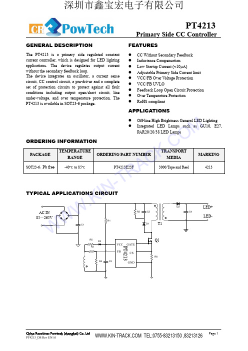
Figure 1 illustrates a simplified flyback converter. When the switch Q1 turns on, the voltage across the primary winding is Vbus. Assuming the voltage dropped across Q1 is zero, the current in Q1 ramps up linearly at
The PT4213 consists of an oscillator, feedback circuit, limit circuit, leading-edge blanking, and constant current control circuitry. The switching frequency is modulated to regulate the output current to provide a constant current characteristic. It senses and regulates output current from primary side of transformer and is
FEATURES
CC Without Secondary Feedback Inductance Compensation Low Startup Current (<10µA) Adjustable Primary Side Current limit VCC/FB Over Voltage Protection VCC/FB UVLO Feedback Loop Open Circuit Protection Over Temperature Protection RoHS compliant
OB2560 Datasheet_昆仰_140314
Confidential
-2-
en
Recommended operating condition Symbol Parameter Range VCC VCC Supply Voltage 9 to 22V Operating Ambient TA -20 to 85 ℃ Temperature
tia
Pin Configuration The pin map is shown as below for SOT23-6.
O
n-
Br
©On-Bright Electronics
ig ht
co n
fid
Package Dissipation Rating Package RθJA (℃/W) SOT23-6 200
FEATURES
Driving MOSFET Primary-side sensing and regulation without TL431 and opto-coupler High precision constant voltage and current regulation at universal AC input Multi-mode PWM/PFM operation for efficiency improving Good dynamic response Programmable CV and CC regulation Built-in primary winding inductance compensation Programmable cable drop compensation No need for control loop compensation Audio noise free operation Built-in leading edge blanking (LEB) Ultra low start-up current (typ. 1uA) and low operating current (typ. 650uA) Comprehensive protection coverage with auto-recovery Precise external OTP VDD over voltage protection VDD under voltage lockout with hysteresis (UVLO) Cycle-by-Cycle current limiting Feedback loop open protection Output short circuit protection
OB2510RMP
OB2510R
GENERAL INFORMATION
Pin Configuration SOT23-5.
Package Dissipation Rating Package RθJA (℃/W) SOT23-5 200 Absolute Maximum Ratings Parameter Value VDD Voltage -0.3 to 30V FB Input Voltage -0.3 to 7V CS Input Voltage -0.3 to 7V BD Input Voltage -0.3 to 7V Min/Max Operating Junction -40 to 150 ℃ Temperature TJ Min/Max Storage -55 to 150 ℃ Temperature Tstg Lead Temperature 260 ℃ (Soldering, 10secs) Note: Stresses beyond those listed under “absolute maximum
Y:Year Code WW:Week Code(01-52) ZZZ: Lot code
R:Character Code
s: Internal code
TERMINAL ASSIGNMENTS
Pin Num 1 2 3 4 5 Pin Name FB GND CS BD VDD I/O I P I O P Description The voltage feedback from auxiliary winding. Connected to resistor divider from auxiliary winding reflecting output voltage. Ground Current sense input Base drive with current limit for power BJT. Power Supply
ADIADuM隔离DCDC控制器参考设计方案
ADIADuM隔离DC-DC控制器参考设计方案ADIADuM4471隔离DC-DC控制器参考设计方案ADI公司的ADuM4471是一款内嵌MOSFET驱动器和校准器的四通道数字光电隔离DC-DC功率控制器,基于ADI先进iCoupler®技术,该控制器内部集成次边PWM光电隔离反馈补偿回路。
有效减少了外部光电隔离电路和补偿回路的元器件,为实现小型化设计提供了基础。
该控制器输入电压为5V或3V,输出电压范围为:3.3V-24V。
单路输出功率可以达到 2.5W。
四通道可分别灵活独立配置,以满足用户不同的应用需要。
本文介绍了DADuM4471芯片的主要特性、方框图、应用方向。
评估板EVAL-ADuM5211EBZ的主要特性、电路图、材料清单和PCB元件布局图。
The ADuM4470/ADuM4471/ADuM4472/ADuM4473/ADuM44741 are quad-channel, digital isolators with a regulated dc-to-dc isolated power supply controller and an internal MOSFET driver. The dc-to-dc controller has an internal isolated PWM feedback from the secondary side, based on the iCoupler? chip scale transformer technology and complete loop compensation. This eliminates the need to use an optocoupler for feedback and compensates the loop for stability. The ADuM447x isolators provide a more stable output voltage and higher efficiency compared tounregulated isolated dc- to-dc power supplies. The fully integrated feedback and loop compensation in a wide-body SOIC package provide a smaller form factor and 8.3 mm creepage distance solution.The regulated feedback provides a relatively flat efficiency curve over the full output power range. The ADuM447x enable a dc-to-dc converter with a 3.3 V to 24 V isolated output voltage range from either a 5.0 V or a 3.3 V input voltage, with an output power of up to 2.5 W. The ADuM447x isolators provide four independent isolation channels in a variety of channel configurations and data rates.ADuM4471主要特性:Isolated PWM feedback with built in compensationPrimary side transformer driver for up to 2.5 W output power with 5 V input voltageRegulated adjustable output: 3.3 V to 24 VUp to 80% efficiencyQuad dc-to-25 Mbps (NRZ) signal isolation channels200 kHz to 1 MHz adjustable oscillatorSoft start function at power-upPulse-by-pulse overcurrent protectionThermal shutdown5000 V rms isolationHigh common-mode transient immunity: >25 kV/μs20-lead SOIC package with 8.3 mm creepageHigh temperature operation: 105°CADuM4471应用:Power supply start-up bias and gate drivesIsolated sensor interfacesProcess controlsRS-232/RS-422/RS-485 transceivers 图1. ADuM4471方框图EVAL-ADuM4471EBZ 主要特性:ADuM447x circuits, including 5kV rms isolated dc-to-dc convertersSingle supply (default)5 V input to 5 V output (regulated)Reconfigurable to 5 V input to 3.3 V output or 3.3 V input to 3.3 V outputDouble supply5 V input to 15 V output (regulated) and 7.5 V output (unregulated)Reconfigurable to 5 V input to 12 V output (regulated) and 6 V output (unregulated)Footprints for Coilcraft, Inc., and Halo Electronics, Inc., transformer optionsMultiple switching frequency optionsEVAL-ADuM4471EBZ电路图:图2. EVAL-ADuM4471EBZ电路图EVAL-ADuM4471EBZ材料清单:PCB元件布局图:。
RED2501_datasheet_Rev05
1/12 November 2014RED2501LED Controller for LLC convertersFeatures■Advanced LED Controller IC for high efficiency low-cost LLC converters with bipolar transistors and integrated PFC ■ PSR - +/-5% Primary Side Regulation of LED current and voltage with no Flicker ■ 50% duty cycle, variable frequency control of resonant half-bridge ■ Automatic dead-time control andcapacitive mode protection ■Protection modes: ∙ Overload ∙ No-Load∙ Over-temperature∙ Control Loop Fault protection■ Low output capacitance allows live LED connection■ Very low output current ripple <5% ■ Small SO8N IC packageApplications■ Single stage PFC LED drivers without flicker ■ CC or CV LED drivers 5-40WOrder codePart Number Package Packaging RED2501AD-TR13 SO8NTape and reelFigure 1: Block diagramSO8NLimits V COMPMAX +-RCCSRC RESETV COMPMINI STARTDriver LogicI STARTTX1TX2CLKSLEEP POR3.45VShuntRegulatorOscillator CC AmplifierRUN VDDGND-+COMP VFBAnalog ControlStartup V CCLIMV REFSLEEP V DDPrimarySide SensingCV Amplifier-+OTPOver TemperatureProtectionOTPSHUTDOWNSTARTUP F A U L T SFault LogicV COMPMIN =>Max FrequencyVFB HighVFB LowCS Voltage LowDevice PinsFigure 2: SO8N pin connections (top view)Pin FunctionsPin # Name Function1 VFB PSR Feedback input for output voltage regulation. Connect to primary sense winding.2COMP Buffered output of the control amplifiers. A loop compensation network connected between this pin and the VFB input defines CV mode loop response.3 TX2 Output to control transformer.4 TX1 Output to control transformer.5 RC External RC network sets the minimum [full power] switching frequency.6 VDD IC Power Supply pin – nominally 3.45V7 GND Chip ground.8 CS PSR Current Sense input provides output current regulation and cycle-by-cycle over-current protection. The CS pin is connected to the half-bridge current sense resistor12345678GNDCOMPCSVDDRCTX2TX1VFBTypical ApplicationFigure 3: Typical Application Schematic: LLC converter with RED2501 PSR controllerFeaturesRED2501 is an advanced CMOS control IC for resonant LLC converters. The RED2501 Primary Side Regulation (PSR) control scheme accurately controls the LED current and removes the need for secondary side opto-coupler feedback, reducing cost and complexity.RED2501 uses the CSOC (Controlled Self-Oscillating Converter) scheme to drive two low-cost bipolar transistors in a half-bridge configuration. RED2501 is optimized to work with RediSem’s LLC converter topology with integrated Power Factor Correction.Please contact RediSem for application design information for LED drivers with PFC.Accurate Primary Side RegulationThe RED2501 PSR scheme regulates the LED drive current by modulating the converter frequency. Primary side current control enables +/-5% LED current regulation. With the LED disconnected, the RED2501 controls the maximum output voltage and enters fault-mode operation to keep the output voltage from rising and to keep the power consumption low.Protection FeaturesThere are 5 faults that can cause the IC to enter fault mode:∙ VFB pin voltage rises too high (no LEDconnected)∙ VFB pin voltage falls too low (feedbackresistor R fb1 disconnected)∙ CS pin voltage is low (CS pin shorted toGND)∙ Overtemperature fault (discussed later) ∙ Operating frequency rises too highDuring these fault conditions, the IC will continually attempt re-starts. Between each re-start attempt there will be 8 dummy re-starts when the IC re-starts while the converter is off.LsLmCrOutputT1aT1bT1cT1d T2D1D2Cout+_HT+HT-RED2501COMP TX2RC V DD TX1CS VFBGND 123458RauxCauxDauxQ1Q2RcsCcompRrcCddU1T1Crc 6Rcs2Rfb27V OUTRfb1Additionally, if the output is short-circuit, the auxiliary power to the IC fails and the IC shuts down. From this condition the IC automatically cyclically re-starts until the short-circuit has been removed.The IC also has an instantaneous cycle-by-cycle over-current protection (OCP) level that will terminate any cycle instantaneously should the current exceed a pre-set level.Over-temperature ProtectionThe RED2501 Over-temperature protection (OTP) feature shuts down the controller if the IC temperature exceeds 125°C. The IC will restart the converter when the IC temperature drops by 15°C.Automatic Dead-Time ControlAn important feature of the Controlled Self Oscillating Converter is that the dead-time is controlled naturally. Unlike MOSFET half-bridge converters, it is not necessary to program the dead-time on RED2501. The bipolar switching transistors are turned on correctly through the self-oscillation of the converter and turned off by RED2501. This greatly simplifies the design process and improves the robustness of the LLC converter.Capacitive Mode ProtectionRED2501 includes a capacitive mode protection feature which prevents the converter from entering capacitive switching mode on a cycle-by-cycle basis by limiting the minimum frequency. This always ensures the Controlled Self Oscillating Converter continues to oscillate correctly.IC OperationStartup, Shutdown and re-startFigure 4 shows typical startup waveforms for RED2501. In SLEEP mode the IDD current is approximately 8uA (I DDSLEEP ). Once VDD reaches 3.6V (V DDSTART ) the IC enters STARTUP mode. During this period of approximately 10ms (512 cycles) Vdd is allowed to drop to 2.4V or rise to 3.6V. This gives time for the application to pull up the output voltage. After this the IC enters RUN mode when the controlled Zener clamp inside the IC regulates the VDD voltage to 3.45V (V DDREG ). The IC current is now approximately 0.7mA (I DDREG ) plus any excess current required to clamp VDD to 3.45V. If VDD falls below 3.45V (V DDREG ) the Zener clamp turns off and I DD reduces to 0.7mA (I DDREG ) only. If VDD falls below 3.0V (V DDSLEEP ), the IC enters SLEEP mode. In this condition I DD reduces to 8uA. (I DDSLEEP ).Figure 4: IC Start-up waveformsOutput stageA diagram of the output stage can be seen in Figure 5. To start the converter oscillating the RED2501 issues start pulses through the TX pins during the first two cycles. These start pulses are 500ns long (t TXSTART ) and provide 14mA (I TXSTART ) current pulses from both TX1 and TX2 pins. After this the converter self-oscillates and no longer needs start pulses to maintainoscillation. A low on-state NMOS transistor is used to turn the bipolar transistors off. It is controlled by the oscillator off-time. The NMOS device is turned to pull TX pin low, which switches off the corresponding bipolar transistor in the power converter half-bridge.Figure 5: Output StageTX1 / TX2V DDStart PulseI TXSTARTClamp TimeDrive StageT X 1T X 2T X 1T X 2T X 1T X 2T X 1T X 2TX Pin voltageRC Pin voltageCS Pin voltageT X 1V DD voltageI DD currentT X 1T X 2T X 1T X 2SLEEP MODE RUN MODETIMEV DDSTART V DDREG I DDRUNI DDSLEEPStartpulsesV DDSLEEPSLEEP MODE T X 2T X 2T X 1T X 2T X 1Power DownSleep10ms (512 cycles)STARTUP MODE STARTUP MODEPrimary Side Regulation (PSR)The converter’s output current and voltage are estimated by the RED2501 PSR scheme. Inside the IC there are two separate control loops that control the converter output current (in CC mode) and voltage (in CV mode). The RED2501 regulates the output current and voltage bycontrolling the frequency. A control voltage (V COMP ) is fed into the oscillator to give the desired operating frequency. Figure 6 shows how the two current and voltage error amplifiers and their compensation networks are configured for a primary regulated LLC converter.Figure 6: Error Amplifier CircuitsCV IntegratorOscillator Control VoltageCCIntegratorV CCREGLimitsV COMPMINV REFCFBVFBV DDVFB Sensing Signal-+-+COMPR CFBRfb1Rfb2V COMPMAX Primary Sensing Signal DetectionC CFBC COMPPSR Average Current CSAVGMain ConverterPrimary Current CS Resistor 100RCSFigure 7: RED2501 Current protection and control circuitsPSR Current ControlFigure 7 shows the two current control methods used in the converter:1. constant current (CC) regulation;2. an instantaneous peak current limit(OCP).PSR Average current estimationShown in figure 7 the signal from the CS pin is divided into two different paths. The bottom path provides peak instantaneous over-current protection (OCP) while the PSR Average Current estimation block provides the current regulation (CC) information. The voltage on the CS pin is an AC signal biased around GND. Inside the PSR block this signal is processed to provide a voltage proportional to the average converter output current.Constant Current RegulationThe CC regulation circuit is shown in Figure 7. CC operation is defined by an internally compensated control loop. This provides a system response time of approximately 300us in a typical application. The average current regulation point, V CCREG is pre-set to 150Error! Reference source not found.mV, referred to the CS pin.Over Current ProtectionOver-Current Protection (OCP) is an instantaneous termination of the current oscillator cycle and the transistor on-time. When a peak voltage greater than +/-500mV (VOCPTHR) is sensed on the CS pin the OCP comparator terminates the current oscillator on-time cycle. The oscillator is reset and the off-time begins resulting in the bipolar transistors turning off and the half-bridge commutating. This is repeated in subsequent cycles whenever the CS voltage exceeds the threshold. However, in a correctly designed converter it should not be possible to trip OCP in normal operation.PSR Voltage ControlThe RED2501 voltage control loop is used to control the maximum LED converter output voltage. The VFB input senses the output voltage from an auxiliary winding on the primary side of the transformer. This signal is conditioned in the PSR block and compared to a voltage reference of 1.2V (V REF ) inside the IC. If the voltage exceeds 1.2V RED2501 will enter shutdown. In a constant current LED application the VFB voltage will normally be below the 1.2V regulation point V REF as the CC control loop determines the COMP voltage. If the LED voltage is too high, or the LED becomes disconnected, the CC loop is not in control and the VFB voltage will rise to the 1.2V V REF control voltage. At that point RED2501 will shut down and enter fault mode, re-starting regularly to check if the fault has been removed To operate the RED2501 in CV mode as well as CC mode, connect an external feedback network as shown in figure 6 between the COMP and VFB pins. This defines the loop gain and phase for the voltage control loop. RED2501 includes a VFB feedback protection feature that stops the converter if the PSR feedback signal to the VFB pin is lost.PSR average current estimator+-+-OCP ComparatorOscillator ResetCC IntegratorV CCREGV OCPTHRTo Oscillator ComparatorMain Converter Primary CurrentCS Resistor100RCS PinCS AVGOscillatorThe oscillator (see Figure 8) controls the period of a converter half-cycle. Internal to the IC is an oscillator comparator that compares the voltage on the RC pin to the voltage on the COMP pin. The RC pin has a saw tooth type waveform and the COMP signal should have a steady voltage, inversely proportional to the required frequency. The COMP pin voltage can vary from 0.55V (V COMPMIN ) to 2.35V (V COMPMAX ), resulting in a maximum to minimum frequency ratio of nearly 5x for any input voltage. The timing capacitor C RC may be chosen within the range 100 – 1000 pF. The recommended type is a 5% COG/NPO capacitor.The oscillator timing resistor R RC may be connected to either V DD or to the rectified DC bus, V HT . If connected to V DD , the value of R RC may be calculated using following equation.F MIN =12(0.0.8us −R RC .C RC .ln (1−2.353.45))This equation gives the lowest possible operating frequency of the converter.Figure 8: Oscillator circuitOscillator Feed-forward CompensationThe oscillator may optionally include feed-forward compensation. Feed-forward compensation is recommended to minimise the line frequency ripple on the output. To apply the feed-forward compensation, the oscillator pull-up resistor R RC is connected to the DC bulk supply V HT instead of V DD . The value may be calculated as a function of the DC bulk voltage using the following equation:F MIN =12(0.8us +R RC .C RC .2.35/V HT )To assist feed-forward applications, a switch is provided which connects the VDD pin to the RC pin while the controller is in SLEEP. This allows the R RC resistor to pull up the VDD supply for start up.+-Oscillator ComparatorDrive LogicRCV HT or V DDSLEEPCOMPR RCC RCRC Pin DischargeTo TX1 / TX2 DriversVDDCOMPABSOLUTE MAXIMUM RATINGSCAUTION: Permanent damage may result if a device is subjected to operating conditions at or in excess of absolute maximum ratings.Parameter Symbol Condition Min Max Unit Supply voltage V DD-0.5 4.0 V Supply current I DD0 10 mAInput/output voltages V IO-0.5 V DD +0.5VInput/output currents I IO-10 10 mA Junction temperature T J T J_MAX limited by OTP (T OTPS_MAX) -20 +135 °C Storage temperature T P-20 +125 °C Lead temperature T L Soldering, 10 s 260 °CESD withstand Human body model, JESD22-A114 2 kV Capacitive Discharge Model 500 VNORMAL OPERATING CONDITIONSUnless otherwise stated, electrical characteristics are defined over the range of normal operating conditions. Functionality and performance is not defined when a device is subjected to conditions outside this range and device reliability may be compromised.Parameter Symbol Condition Min Typ Max Unit Minimum supply current I DDMIN0.8 1.0 1.2 mA Junction temperature T J-20 25 125 °CELECTRICAL CHARACTERISTICSUnless otherwise stated:∙Min and Max electrical characteristics apply over normal operating conditions.∙Typical electrical characteristics apply at T J = T J(TYP) and I DD = I DDREG(TYP).∙The chip is operating in RUN mode.∙Voltages are specified relative to the GND pin.VDD PinParameter Symbol Condition Min Typ Max UnitSupply voltage V DDSTART To enter RUN mode 3.2 3.6 4.0 V V DDREG I DD< I DDSHUNT 3.3 3.45 3.6 V V DDSLEEP To enter SLEEP mode 2.8 3.0 3.2 VSupply current I DDREG In RUN mode, VDD<VDD REG0.7 0.8 mA I DDSLEEP In SLEEP mode 8 12 µA I DDSHUNT VDD shunt regulator max current 8 mAVFB PinParameter Symbol Condition Min Typ Max Unit VFB threshold voltage V REF T J= 0°C to 85°C, V DD=3.45V 1.15 1.20 1.25 VCS PinParameter Symbol Condition Min Typ Max Unit Constant current regulation V CCREG DC CS signal. T J= 0°C to 85°C 146 150 154 mV Instantaneous over-currentprotection thresholdVOCPTHR 500 mV RC PinParameter Symbol Condition Min Typ Max Unit External capacitor range C RC100 1000 pFOscillator Frequency Variation ∆F RC/F RCT J= -0°C to 85°C, C RC=330pF,V DD=3.45V, V COMP= V COMPMAX4 %Oscillator reset time T RCRST0.7 µsCOMP PinParameter Symbol Condition Min Typ Max Unit Source/Sink current I COMP-40+40 µA Maximum COMP voltage V COMPMAX V DD=3.45V 2.35 V Minimum COMP voltage V COMPMIN V DD=3.45V 0.55 VTX1, TX2 PinsParameter Symbol Condition Min Typ Max Unit On-state resistance R TXON 1.5 2 ΩTX pin clamp current I TXCLAMP TX pin frequency >30kHz 800 mA Start-pulse output current I TXSTART TX pin voltage 2V 14 mA Start-pulse width T TXSTART500 nsOver-Temperature Protection (OTP)*Parameter Symbol Condition Min Typ Max Unit Over-TemperatureProtection thresholdT OTPS At silicon junction 115 125135 ︒C Over-TemperatureProtection reset hysteresisT OTP_HYS At silicon junction 15︒C *: not tested in productionPACKAGE INFORMATIONPackage DimensionsSO8N package dimensions are shown below. All units are in mm.Available packagesPackage typePart number Moisture Sensitivity Level (MSL)Packaging SO8NRED2501AD-TR133 (JE D E C J-ST D -020)T ape and reel 2500 / 13” reelPackage Marking0.18 ± 0.071.55 ± 0.180.42 ± 0.064.89 ± 0.093.9 ± 0.096.01 ± 0.191.270.22 ± 0.030.270 - 8º0.38 x 45ºRediSem RED2501 WXYZSO8N top-side marking for RED2501RED2501= Part NumberWXYZ= Lot Code, e.g. AAAA, AAABStatusThe status of this Datasheet is shown in the footer.Datasheet Status ProductStatusDefinitionPreview In development The Datasheet contains target specifications relating to design anddevelopment of the described IC product.Preliminary In qualification The Datasheet contains preliminary specifications relating to functionalityand performance of the described IC product.Production In production The Datasheet contains specifications relating to functionality andperformance of the described IC product which are supported by testingduring development and production.Contact DetailsRediSem Ltd.301-302 IC Development CentreNo 6 Science Park West AvenueHong Kong Science & Technology ParkShatin, New TerritoriesHong KongTel. +852 2607 4141Fax. +852 2607 4140Email:info@Web: DisclaimerThe product information provided herein is believed to be accurate and is pro vided on an “as is” basis. RediSem Ltd assumes no responsibility or liability for the direct or indirect consequences of use of the information in respect of any infringement of patents or other rights of third parties. RediSem Ltd does not grant any licence under its patent or intellectual property rights or the rights of other parties.Any application circuits described herein are for illustrative purposes only. Specifications are subject to change without notice. In respect of any application of the product described herein RediSem Ltd expressly disclaims all warranties of any kind, whether express or implied, including, but not limited to, the implied warranties of merchantability, fitness for a particular purpose and non-infringement of third party rights. No advice or information, whether oral or written, obtained from RediSem Ltd shall create any warranty of any kind. RediSem Ltd shall not be liable for any direct, indirect, incidental, special, consequential or exemplary damages, howsoever caused including but not limited to, damages for loss of profits, goodwill, use, data or other intangible losses.The products and circuits described herein are subject to the usage conditions and end application exclusions as outlined in RediSem Ltd Terms and Conditions of Sale.RediSem Ltd reserves the right to change specifications without notice. To obtain the most current product information available visit or contact us at the address shown above.。