(HDMI VGA CVBS)视频信号发生器 使用说明书
HDMI高清编码器中文说明书H265-H264

H.265/H.264高清视频编码器上海禾鸟电子科技有限公司荣誉出品一、产品简介H.265/H.264高清视频编码器有HDMI\SDI\VGA三种高清接口产品,是由上海禾鸟电子自主研发的用于高清视频信号编码及网络传输直播的硬件设备,采用最新高效H.265/H.264高清数字视频压缩技术,具备稳定可靠、高清晰度、低码率、低延时等特点。
输入高清HDMI、SDI、VGA高清视频、音频信号,进行编码处理,经过DSP芯片压缩处理,输出标准的TS网络流,直接取代了传统的采集卡或软件编码的方式,采用硬编码方式,系统更加稳定,图像效果更加完美,广泛用于各种需要对高清视频信号及高分辨率、高帧率进行采集并基于IP 网络传送的场合,强大的扩展性更可轻易应对不同的行业及需求,可作为视频直播编码器,录像,传输等应用。
采用工业控制精密设计,体积小,方便安装,功率小于5W,更节能,更稳定。
特点:●高性能硬件编码压缩●支持H.265高效视频编码●支持H.264 BP/MP/HP●支持AAC/G.711高级音频质编码格式●CBR/VBR码率控制,16Kbps~12Mbps●网络接口采用100M、1000M 全双工模式●主流,副流可推流不同的服务器●支持高达720P,1080P@60HZ的高清视频输入●支持图像参数设置●HDMI编码支持HDCP协议,支持蓝光高清●支持HTTP,UTP,RTSP,RTMP,ONVIF 协议●主流与副流采用不同的网络协议进行传输●WEB操作界面,中英文配置界面可选●WEB操作界面权限管理●支持广域网远程管理(WEB)●支持流分辨率自定义输出设置●支持码流插入中英文字功能,字体背景、颜色可选●支持码流插入3幅透明图像水印功能,XY轴可设置●支持一键恢复出厂配置二、产品应用:1、4G移动直播高清前端采集2、高清视频直播服务器3、视频会议系统视频服务器4、数字标牌高清流服务器5、教学直播录像系统前端采集6、IPTV电视系统前端采集7、微信直播系统前端采集8、医疗视频直播与录像系统9、可接入NVR硬盘录像机三、接口说明:HDMI高清编码器(H265、H264)SDI高清编码器(H265、H264)VGA高清编码器(H265、H264)HDMI高清编码器(H264)SDI高清编码器(H264)VGA高清编码器(H264)3U结构编码器说明:A、电源输入----- 12V/DC 输入接口,采用12V1A电源,如果是5V输入时,选用5V/2AB、初始化按钮------用于复位设备,当开机后,按住不放15秒后,设备IP恢复至出厂IP,192.168.0.31C、视频输入------用于输入高清HDMI、SDI、VGA、Audio信号。
HDMI高清光端机产品说明书
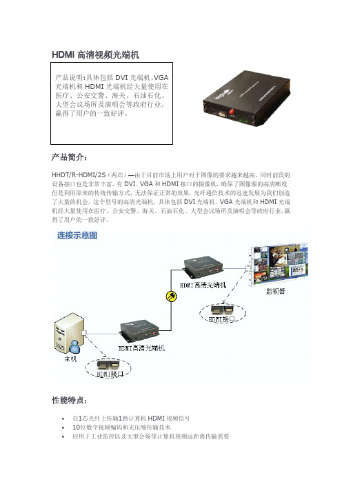
HDMI 高清视频光端机产品简介:HHDT/R-HDMI/2S (两芯)—由于目前市场上用户对于图像的要求越来越高,同时前段的设备接口也是非常丰富,有DVI 、VGA 和HDMI 接口的摄像机,确保了图像源的高清晰度,但是利用原来的传统传输方式,无法保证正常的效果,光纤通信技术的迅速发展为我们创造了大量的机会,这个型号的高清光端机,具体包括DVI 光端机、VGA 光端机和HDMI 光端机经大量使用在医疗、公安交警、海关、石油石化、大型会议场所及演唱会等政府行业,赢得了用户的一致好评。
性能特点:•在1芯光纤上传输1路计算机HDMI 视频信号•10位数字视频编码和无压缩传输技术•应用于工业监控以及大型会场等计算机视频远距离传输需要•严格的物料选择和质量控制确保产品高品质和高可靠•可选的VGA/RGB,DVI接口,支持高保真立体声音频和RS232/485数据通道•电源和其它参数指示LED可监视系统状态•紧凑的尺寸•优异的性价比•SMT表面贴装技术•同时可以支持4U机箱、1U机箱和独立式结构•低功耗和即插即用的免调试安装规格参数:1、视频•通道数量:1•视频规格:HDMI•输入电平:1Vp-p•输出电平:1Vp-p•带宽(-3dB):300MHz•数码位宽:10bit•分辨率:VGA640x48060、70、75、85HzSVGA800x60060、70、75、85HzXGA1024x76860、70、75、85HzSXGA280x102460、70、75、85HzUXGA1600x120060Hz1920x108050/60Hz接口:HD-15(VGA、DVI可选)2、电源及环境指标•独立式功率:5W•插卡式功率:5W•电源适配器:220VAC to12VDC/1A•工作温度范围:-40°C to+70°C•相对湿度:<95%(无冷凝)3、电源及环境指标•独立式尺寸(mm):184L x140W x45H•插卡尺寸(mm):260L x173W x40H•独立式重量(kg):2.0•插卡重量(kg):1.54、光学•波长:1310/1550nm•光纤类型:单模•最大链路损耗:12dB(更大可选)•输出光功率:–5~–10dBm•接收灵敏度:-18dBm•连接器FC/PC(SC或ST可选)应用场合:电视演播现场转播搜索关键词:光端机、视频光端机、数字视频光端机、数据光端机、广播级视频光端机、SDI数字标清光端机、ASI数字标清光端机、TS流光端机、HD-SDI数字高清光端机、AES光端机、AES\EBU数字音频光端机、VGA视频光端机、DVI视频光端机、HDMI光端机、HDMI 视频光端机、HDMI高清视频光端机。
HDCVI Video Converter用户手册说明书

HDCVI Video ConverterUser’s ManualV1.0.0Important Safeguards and WarningsPlease read the following safeguards and warnings carefully before using the product in order to avoid damages and losses.Note●Do not expose the device to lampblack, steam or dust. Otherwise it may cause fire or electricshock.●Do not install the device at position exposed to sunlight or in high temperature. Temperaturerise in device may cause fire.●Do not expose the device to humid environment. Otherwise it may cause fire.●The device must be installed on solid and flat surface in order to guarantee safety under loadand earthquake. Otherwise, it may cause device to fall off or turnover.●Do not place the device on carpet or quilt.●Do not block air vent of the device or ventilation around the device. Otherwise, temperature indevice will rise and may cause fire.●Do not place any object on the device.●Do not disassemble the device without professional instruction.Warning●Please use battery properly to avoid fire, explosion and other dangers.●Please replace used battery with battery of the same type.●Do not use power line other than the one specified. Please use it properly. Otherwise, it maycause fire or electric shock.Special Announcement●This manual is for reference only.●All the designs and software here are subject to change without prior written notice.●All trademarks and registered trademarks are the properties of their respective owners.●If there is any uncertainty or controversy, please refer to the final explanation of us.●Please visit our website for more information.Table of Contents1Product Overview......................................................................................................... - 1 -1.1 Product Features ................................................................................................................... - 1 - 1.2 Typical Application ................................................................................................................. - 1 - 2Device Structure........................................................................................................... - 2 -2.1 Front Panel ....................................................................................................................... - 2 - 2.2 Rear Panel ........................................................................................................................ - 3 - Appendix 1 Technical Specifications ............................................................................ - 4 -Appendix 2 Toxic or Hazardous Materials or Elements ........................................... - 5 -1 Product Overview1.1 Product Features●Self-adaptive output HDCVI, HDMI, VGA, CVBS signal.●Lossless, real time, non-compression.●Support 2 dial switches and indicate 4 Baud rate 2400b/s, 4800b/s, 9600b/s and 115200b/s.●LED status indicator shows the working condition of video converter.●Fully enclosed dustproof design1.2 Typical ApplicationThe typical application of HDCVI video converter is shown in Figure 1-1Figure 1-1Note:●VGA, HDMI Port :When input CVI video format is 720P, output is 720P/60.When input CVI video format is 1080P, output is 1080P/60.●CVBS Port :When input CVI is 25frame, 50frame, output is PAL format.When input CVI is 30frame, 60frame, output is NTSC format.Fixed aspect ratio, output according to 4:3.2 Device Structure2.1 Front PanelThe front panel of HDCVI video converter is shown in Figure 2-1.Figure 2-1For indicator, please refer to sheet 2-1. For ports, please refer to sheet 2-2. For Baud rate, please refer to sheet 2-3.2.2 Rear PanelThe rear panel of HDCVI video converter is shown in Figure 2-2Figure 2-2 For ports, please refer to sheet 2-4.Appendix 1 Technical SpecificationsAppendix 2 Toxic or Hazardous Materials or ElementsO: Indicates that the concentration of the hazardous substance in all homogeneous materials in the parts is below the relevant threshold of the SJ/T11363-2006 standard.X: Indicates that the concentration of the hazardous substance of at least one of all homogeneous materials in the parts is above the relevant threshold of the SJ/T11363-2006 standard. During the environmental-friendly use period (EFUP) period, the toxic or hazardous substance or elements contained in products will not leak or mutate so that the use of these (substances or elements) will not result in any severe environmental pollution, any bodily injury or damage to any assets. The consumer is not authorized to process such kind of substances or elements, please return to the corresponding local authorities to process according to your local government statute.Note●This user’s manual is for reference only.●Slight difference may be found in user interface.●All the designs and software here are subject to change without prior written notice.●All trademarks and registered trademarks are the properties of their respective owners.●If there is any uncertainty or controversy, please refer to the final explanation of us.●Please visit our website for more information.。
诺瓦科技LED视频处理器Thunderview_V1规格书

Thunderview_V1视频处理器版本编号: V1.0.0 文档编号:NS160010171规格书西安诺瓦电子科技有限公司版权所有 ©2017 西安诺瓦电子科技有限公司。
保留一切权利。
非经本公司书面许可,任何单位和个人不得擅自摘抄、复制本文档内容的部分或全部,并不得以任何形式传播。
商标声明是诺瓦科技的注册商标。
声明欢迎您选用西安诺瓦电子科技有限公司(以下简称诺瓦科技)的产品,如果本文档为您了解和使用产品带来帮助和便利,我们深感欣慰。
我们在编写文档时力求精确可靠,随时可能对内容进行修改或变更,恕不另行通知。
如果您在使用中遇到任何问题,或者有好的建议,请按照文档提供的联系方式联系我们。
对您在使用中遇到的问题,我们会尽力给予支持,对您提出的建议,我们衷心感谢并会尽快评估采纳。
网址:http://www.novastar.tech西安诺瓦电子科技有限公司规格书目录目录1 概述 (1)2 功能特性 (2)3 硬件介绍 (3)4 尺寸 (5)5 规格参数 (6)西安诺瓦电子科技有限公司规格书 1 概述1 概述Thunderview_V1是一款由诺瓦科技研发的视频处理器,其基于一个强大的FPGA处理平台,支持包括2路SDI,1路DP,1路CVBS,1路VGA,3路HDMI,1路DVI及1路HDBT等多样化的信号输入,输入分辨率最高支持4096x2160@60Hz,超高清画面的输入输出,延迟时间短并且信号源切换速度仅为0.25s,可以为您带来更加极速的操作体验。
西安诺瓦电子科技有限公司规格书 2 功能特性2 功能特性●Thunderview_V1具有完备的视频输入接口,包括2路SDI,1路DP,1路CVBS,1路VGA,2路HDMI2.0,1路HDMI1.3,1路DVI,1路HDBT;●支持的输入分辨率最高可达4096x2160@60Hz;●Thunderview_V1可根据显示屏分辨率对输入图像进行缩放;●画中画的位置、大小等均可调节,可以随心所欲的控制;●1路S/PDIF,外置独立音频输出;●支持多台拼接带载;●Thunderview_V1无须通过计算机软件进行系统配置。
信号发生器使用说明
Function GeneratorModel : GFG-3015Operation Manual82FG-30150MBiTable of ContentsPage1. Precautions......................................................................................................................... 2 2. Product Introduction.......................................................................................................... 5 3. Features .............................................................................................................................. 6 4. Specifications ..................................................................................................................... 7 5. Front and Rear Panels ..................................................................................................... 10 6. Operation .......................................................................................................................... 18 6.1 The First Step Setup For Instrument .................................................................... 18 6.2 The Setup of Output Function............................................................................... 18 6.3 The Setup of Frequency......................................................................................... 18 6.4 The Setup of Amplitude ......................................................................................... 19 6.5 The Setup of Offset ................................................................................................ 19 6.6 The Setup of Duty................................................................................................... 20 6.7 The Setting of STORE ............................................................................................ 20 6.8 The Setting of RECALL .......................................................................................... 20 6.9 The SHIFT Key and Function Keys ....................................................................... 21 6.10 Setup of LIN or LOG Sweep................................................................................. 21 6.11 Setup of AM Modulation ...................................................................................... 25 6.12 Setup of FM Modulation....................................................................................... 26 6.13 Setup of Trigger.................................................................................................... 28 6.14 Setup of GATE and BURST ................................................................................. 30 6.15 Setup of External Counter ................................................................................... 32 6.16 THE VCF Function ................................................................................................ 34 6.17 THE GCV Output Function................................................................................... 35 6.18 THE TTL Signal Output Function ........................................................................ 36 6.19 THE SYNC Signal Output Function..................................................................... 36 6.20 Remote Control - RS232 Interface ...................................................................... 36 6.21 Commands Syntax ............................................................................................... 38 6.22 The Commands of RS-232 Serial Interface ........................................................ 41 6.23 The Examples of the Communication Interface Software ................................ 44 6.24 The Error message of instrument ....................................................................... 47 7. Adjustment and Correction ............................................................................................. 48 7.1 Preparation.............................................................................................................. 48 7.2 Adjust and Check up the operation DC Voltage.................................................. 48 7.3 Adjusting Main Clock ............................................................................................. 49 7.4 Adjusting Sensitivity of counter ........................................................................... 49 7.5 Adjusting VCF Function 100:1 .............................................................................. 49 7.6 Adjusting Main Frequency , Duty Cycle and GCV Output Check ...................... 49 7.7 Adjusting Rise/Fall Time........................................................................................ 50 7.8 Adjusting Main Sine wave Harmonic Distortion.................................................. 50 7.9 Adjusting Modulation source ................................................................................ 50 7.9.1 Adjusting Rate and symmetry............................................................................ 50 7.9.2 Adjusting Sine wave Harmonic Distortion ........................................................ 51 7.10 Adjusting AM modulation .................................................................................... 51 7.11 Adjusting FM and Sweep Function..................................................................... 53 7.12 Adjusting Trigger Phase ...................................................................................... 55 7.13 Calibrating by Software ....................................................................................... 56 8. The Block Diagram and Description of the System ...................................................... 62iiEC Declaration of ConformityWeGOOD WILL INSTRUMENT CO., LTD.No. 7-1, Jhongsing Rd, Tucheng City,Taipei County 236, TaiwanGOOD WILL INSTRUMENT (SUZHOU) CO., LTD.No. 69, Lushan Road, Suzhou New District Jiangsu, Chinadeclares that the below mentioned productGFG-3015is herewith confirmed to comply with the requirements set out in the Council Directive on the Approximation of the Law of Member States relating to Electromagnetic Compatibility (89/336/EEC, 92/31/EEC, 93/68/EEC) and Low Voltage Equipment Directive (73/23/EEC, 93/68/EEC). For the evaluation regarding the Electromagnetic Compatibility and Low Voltage Equipment Directive, the following standards were applied:◎ EMC EN 61326-1: Electrical equipment for measurement, control and laboratory use –– EMCrequirements (1997+A1: 1998+A2: 2001) Conducted and Radiated Emissions Electrostatic Discharge EN 55011: 1998 class A EN 61000-4-2: 1995+A1:1998 Current Harmonic Radiated Immunity EN 61000-3-2: 2000 EN 61000-4-3: 1996+A1:1998 Voltage Fluctuation Electrical Fast Transients EN 61000-3-3: 1995 EN 61000-4-4: 1995 Surge Immunity ------------------------EN 61000-4-5: 1995 Conducted Susceptibility ------------------------EN 61000-4-6: 1996 Power Frequency Magnetic Field ------------------------EN 61000-4-8 : 1993 Voltage Dips/ Interrupts ------------------------EN 61000-4-11: 1994◎ SafetyLow Voltage Equipment Directive 73/23/EEC & amended by 93/68/EECSafety Requirements IEC/EN 61010-1: 2001GFG-3015p.11. PrecautionsGFG-3015 is specially designed for safety operation. It has passed through rigorous tests of inclement environment to ensure its reliability and good condition. The following precautions are recommended to insure your safety and keep the best condition of the equipment. (1) Safety Terms and Symbols The following terms and symbols may appear in this manual:! !This statement identifies conditions or practices that could result in injury or loss of life. This statement identifies conditions or practices that could CAUTION result in damage to this product or other properties. WARNINGThe following terms and symbols may appear on the product: This term indicates an immediately accessible injury hazard. DANGER This term indicates that an injury hazard may occur, but is WARNING not immediately accessible. This term indicates potential damage to this product or other CAUTION properties.!DANGER High voltage Protective Conductor Terminal ATTENTION refer to manual Double Insulated DANGER Hot surface Earth Ground Terminal(2) Do not place any heavy objects on the instrument under any circumstances.(3) Disassembling the instrument Due to the precision of this instrument, all the procedures of disassembling, adjusting, and maintenance should be performed by a professional technician. If the instrument has to be opened or adjusted under some unavoidable conditions, and to be managed by a technician who is familiar with GFG-3015. Once there is any abnormality, please contact our company or our distributor near you. (4) Power Supply AC input should be within the range of line voltage±15%, 50/60Hz. To prevent the instrument from burning up, be sure to check the line voltage before turning on power.p. 2GFG-3015(5) Grounding!WARNINGTo avoid electrical shock, the power cord protective grounding conductor must be connected to ground.GFG-3015 can be operated only with an earth grounded AC power cord that connects the case and ground well. This is to protect the user and the instrument from the risk of shock hazard. (6) Fuse Replacement!WARNINGFor continued fire protection, replace fuse only with the specific type and rating by qualified personnel. Disconnect the power cord before replacing fuse.The fuse blows only when there is any wrong on the instrument, which will stop working under this situation. Please find out the cause, then open the outside case (Please see the Figure (A), Figure (B) on below) and replace a proper fuse as listed below. Be sure to use the correct fuse before changing the applying location. F101 : T 0.8A/250V F100 : T 0.5A/250V Check the line voltage setting on the rear panel. If the line voltage setting does not match, Please change the line voltage setting according to the following steps: 1. Remove line cord from AC socket. 2. Switch the “AC line voltage switch” to correct setting with flat-blade screwdriver and reinsert.Figure (A) (7) Cleaning the Cabinet Disconnect the AC power cord before cleaning the instrument.Figure (B)Use a soft cloth dampened in a solution of mild detergent and water. Do not spray cleaner directly onto the instrument, since it may leak into the cabinet and cause damage. Do not use chemicals containing benzing, benzne, toluene, xylene, acetone, or similar solvents.GFG-3015p.3(8) Operation environment Indoor use Altitude up to 2000m Temperature to satisfy the specification : Operating temperature : Storage temperature : Relative humidity : Installation category: Pollution degree:18oC ~ 28oC (+64.4oF ~ +82.4oF) 0oC ~ 40oC (+32oF ~ +104oF) -10oC ~ 70oC (+14oF ~ 158oF) up to 90% when 0oC~35oC; up to 70% when 35oC~40oC CAT Ⅱ(The detail is as Table A) 2CAT Ⅳ CAT Ⅲ CAT Ⅱ CAT ⅠTable A For measurements performed at the source of the lowvoltage installation. For measurements performed in the building installation. For measurements performed on circuits directly connected to the low-voltage installation. For measurements performed on circuits not directly connected to Mains.(9) Place GFG-3015 in a location with a suitable environment as stated above free from dust, direct exposition of sunlight, and strong effect of magnetic fields. (10) For United KingdomAs the colours of the wires in mains leads may not correspond with the coloured markings identified in your plug/appliance, proceed as follows: The wire which is coloured Green and Yellow must be connected to the Earth terminal marked with the letter E or by the earth symbol or coloured Green or Green and Yellow. The wire which is coloured Blue must be connected to the terminal which is marked with the letter N or coloured Blue or Black. The wire which is coloured Brown must be connected to the terminal marked with the letter L or P or coloured Brown or Red. If in doubt, consult the instructions provided with the equipment or contact the supplier. This cable/appliance should be protected by a suitably rated and approved HBC mains fuse; refer to the rating information on the equipment and/or user instructions for details. As a guide, cable of 0.75mm2 should be protected by a 3A or 5A fuse. Larger conductorsNOTEThis lead/appliance must only be wired by competent persons.WARNINGTHIS APPLIANCE MUST BE EARTHEDIMPORTANTThe wires in this lead are coloured in accordance with the following codes: Green/Yellow :Earth Blue :Neutral :Live Brownwould normally require 13A types, depending on the connection method used. Any moulded mains connector that requires removal/replacement must be destroyed by removal of any fuse and fuse carrier and disposed of immediately, as a plug with bared wires is hazardous if engaged in a live socket. Any re-wiring must be carried out in accordance with the information detailed in this section.(Phase)p. 4GFG-30152. Product IntroductionThe frequency feedback method applied by GFG-3015 is a new technique that generates stable output frequency with extraordinary accuracy for Function Generator. The traditional function generators typically use integrating circuit and constant current circuit techniques that are easily affected by operation temperature or the quality of resistor or capacitor and other key components to occur poor frequency accuracy. The innovative design for GFG-3015 is to get rid of these problems. The frequency feedback system needs a compatible, powerful frequency counter. GW has designed his own full-function counter chip, GFC-9701, for this system with high frequency test range and full functions, including Period test, Duty test, Ratio test, Time interval, Pulse wide, direct display and direct connect with CPU system. GFG-3015 uses this Chip to read output frequency value at any time. Then CPU will modify the correct value of D/A converter immediately according to this value, so that the user can get a high accuracy frequency from GFG-3015 Function Generator. Besides, the GFG-3015 can also generate a high accuracy frequency to provide high frequency resolution.Graph1 indicates the fundamental construction of a frequency feedback system.D/A ConvertorVCOAMPO/PUser InterfaceCPUCounter (GFC-9701)Except the different design from the typical circuit, GFG-3015 system also has micro controller (CPU unit) equipping an additional RS-232 interface functions which will be used on any test system with other instrument or to be controlled by computer.GFG-3015p.53. FeaturesGFG-3015 is a functional Function generator that applies Frequency feedback control system technique and can generate high frequency accuracy with high resolution. Its main signal source can generate waveforms including sine wave, square wave, triangle wave, and ramp wave. There are additional features listed as follows: All digitized operation user interface Output Waveforms of Sine, Square, Triangle, Ramp, Pulse, AM, FM, Sweep, Trigger and Gate or Burst. Wide output frequency range 0.01Hz ~ 15MHz. High frequency accuracy 0.02% ± 5 count. Maximum frequency resolution 10mHz. Dual displays indicate frequency and amplitude or other necessary information. Built-in 6-digit INT/EXT Function Counter and up to 150MHz frequency range with high resolution. INT/EXT AM/FM Modulation with internal modulation signal output. LIN/LOG Sweep Mode with internal sweep signal output. VCF of 100:1 EXT Frequency Control. SYNC Output. TTL Output. Synchronization GCV Output. Variable DC Offset Control Output Overload Protection RS232 Interface Standardp. 6GFG-30154. SpecificationsOutput Waveforms Sine, Square, Triangle, ± Ramp, Pulse, AM, FM, Sweep, Trigger, Gate or Burst 1.5001MHz ~ 15.0000MHz …(100Hz) 150.01kHz ~ 1.50000MHz…(10Hz) 15.001kHz ~ 150.000kHz…(1Hz) 1.5001kHz ~ 15.0000kHz…(0.1Hz); 150.01Hz ~ 1.50000kHz…(10mHz) 15.01Hz ~ 150.00Hz…(10mHz) 1.51Hz ~ 15.00Hz…(10mHz) 0.01Hz ~ 1.50Hz…(10mHz) 0.02% ±5 CountFrequency Range 10mHz~15MHz in 8 Frequency Range (auto switch)Frequency ResolutionFrequency AccuracyOutput Impedance 50Ω ± 10% Range Amplitude Resolution Accuracy Unit Range DC Offset Resolution Accuracy Control Range Duty Resolution Accuracy Sync Output Sine Impedance Level Distortion 10.00V~0.01V (into 50Ω) 4 amplitude ranges | Vac peak | + | Vdc | < 5V 10mV(10.00V~0.01V) ≤3% ±5count at 10Hz~1MHz ≤10% ±5count at 1MHz~15MHz Vpp, Vrms, dBm ± 5V (into 50Ω) | Vac peak | + | Vdc | < 5V 10mV ≤3% ±3count at Amplitude Min. 80%:20%:80% to 1MHz 1% ≤1% to 1MHz at 50% Duty 50 Ω ±10% >1Vp-p open circuit ≤0.5%(-46dBc) From 10Hz~100kHz ≤-30dBc To 15MHz (Spec. applied form 1Vpp to 10Vpp) ±1% of period + 3ns <18nSec <1% of full scale output at 100HzSquare Triangle and RampAsymmetry Rise or Fall Time Linearity ErrorGFG-3015p.7Sweep ModeSweep Range Sweep Width Rate Sweep output Types Waveform Rate Frequency Range Rate Frequency Accuracy Rate Frequency ResolutionLinear or Log sweep 150kHz~15MHz 15kHz~1.5MHz 1.5kHz~150kHz 150Hz~15kHz 15Hz~1.5kHz 1.5Hz~150Hz 0.15Hz~15Hz 0.01Hz~1.5Hz >100:1(In Same Frequency Range) 0.01Hz~10kHz 0 to≥-5Vp-p into 10k Ω AM, FM, Sweep, Trigger(int/ext), Gate or Burst (Implement by Trigger Type) Sine, Square, Triangle, Ramp or Variable Symmetry Pulse 10mHz~10KHz in 3 Frequency Range (auto switch) 5%±1 countSymmetry Control 90:10:90 ; Resolution:1%10.0kHz~0.1kHz(100Hz) 99Hz~1Hz(1Hz) 0.99Hz~0.01Hz(0.01Hz) Symmetry 90%:10%:90%; Resolution:1% Symmetry Accuracy ±1 count(≤1%) Output Level Modulation Sine Wave Distortion Amplitude Modulation Depth Modulation Frequency Rate Carries -3dB Bandwidth External Sensitivity ≧1Vpp into 10kΩ load ≤2% from 10Hz to 10kHz0~100% 0.01Hz ~ 10kHz(INT) DC~1MHz(EXT) <100Hz to >5MHz ≤10Vpp for 100% modulationFrequency Modulation Deviation 0~±15% Modulation 0.01Hz ~ 10kHz(INT) DC ~ 50kHz(EXT) Frequency Rate External Sensitivity ≤5Vpp for 15% deviationp. 8GFG-3015Start/Stop Phase Range Rate Trigger-90º ~ +80º 0.01Hz~10kHzVCFFrequency Range 0.1Hz ~ 1MHz(Useful to 10MHz) Ext Trig Frequency DC to 1MHz,TTL compatible input level Range Gate or Burst Implement by Trigger setting. 100:1(0 to 10V± 1V) In Same Frequency Range Range Input Linearity <0.5% to 1MHz,<5% to 10MHz Input Impedance 10 k Ω ≧3Vpp LevelTTL Output GCV OutputFan-out >10 TTL Load To set the voltage between 0.2V to 2V as per different Frequency in Same frequency Range INT/EXT Switch Selector Range Accuracy Time Base Resolution Input Impedance Sensitivity 5Hz~150MHz EXT Time Base(10MHz) Accuracy ± 1 count ± 20ppm(23ºC ± 5ºC) after 30 minutes warm up The maximum resolution is 100nHz for 1Hz and 1Hz for 100MHz 1MΩ // 150pF ≤35mVrms(5Hz~100MHz); ≤45mVrms(100MHz~150MHz)Frequency CounterInterface Accessories Power Source Dimensions WeightRS232 GTL-101 × 2, Instruction Manual × 1, Power cord × 1 115/ 230V AC ±15%, Approx. 5kg 50/60Hz 290 (W) × 142 (H) × 346 (D) mmGFG-3015p.95. Front and Rear PanelsFront Panelp. 10GFG-30151POWER button Main Function keys: :Push the button to turn on the power, and the display is activated. Push again the button to turn off the power. Key is to set main output waveform in the cycle of Sine, Triangle and Square. When the key is pressed, the related waveform LEDs will light up accordingly.FUNC2Key is to set main frequency entry mode. Key in the desired value of frequency by using the number keys or Modify keys and Unit keys. When the key is pressed, the FREQ LED (on parameter display area A) will be flashing until other mode is set.FREQKey is to set main amplitude entry mode. Key in the desired value of voltage by using the number keys or Modify keys and Unit keys. When the key is pressed, the AMPL LED (on parameter display area B) will be flashing until other mode is set.AMPLKey is to set main output offset voltage entry mode. Key in the desired value of voltage by using the number keys or Modify keys and Unit keys. When the key is pressed, the OFFS LED (on parameter display area B) will be flashing until other mode is set.OFFSETKey is to set main output Duty Cycle entry mode. Key in the desired value of percentage by using the number keys or Modify keys and Unit keys. When the key is pressed, the DUTY LED (on parameter display area B) will be flashing until other mode is set.DUTY3Modulation/Sweep Function keys:Key is to start performing Amplitude Modulation, Frequency Modulation or Sweep function. When the key is pressed again, the functions will stop. When the key is pressed, the ON/OFF LED (on MOD/SWP Function LED area) will light up, press again the key, the LED will be off. These keys control the functions of sweep and modulation.MOD/ON SOURCEKey is to set Span of Modulation or Sweep entry mode and choose the source of modulation. If set to source choose function, must use Secondary Function mode.SPAN FMKey is to choose the type of modulation between AM and FM. If want to set to FM function, must use Secondary Function mode.AM INT/EXT RATEKey is to set Rate of Modulation, Sweep or Trigger entry mode and choose the signal source of Modulation, Sweep or Trigger. If want to set to signal, must use Secondary Functions mode.GFG-3015p.11STOPKey is to set Start Frequency of Sweep entry mode and Stop Frequency of Sweep entry mode. If set to Stop Frequency of Sweep entry mode, must use Secondary Functions mode.START LOG SKey is to choose the type of Sweep between liner sweep and LOG sweep. If set to LOG sweep, must use Secondary Function mode.LIN S SWP CF SYMKey is to set the Duty cycle of Modulation, Sweep or Trigger source entry mode. Key in the desired value of percentage by using number keys or modify keys and Unit keys. If want to set to center frequency of Sweep function that must use Secondary Functions mode. When the key is pressed, the SYM LED (on parameter display area B) will be flashing until other mode is set. When you use center frequency entry mode then the CF LED (In parameter display area A) will be flashing until other mode is set. The detail operation of these keys. Please refer to the instruction in next Chapter.RECL4System keys:Key is to save or reload the setup parameters of the instrument into or take out from memory; the selected DEFAU numbers is from 0 to 9, up to 10 groups.STORKey is to start performing RS232 interface. Press the key then use rotational knob to change function states (ON or OFF). Press the key again then use rotational knob to change the Baud rate. The cycle order is in 300, 600, 1200, 2400, 4800, 9600 and 19200 sequence. If set the instrument to default state, must use Secondary Function mode. Key is to set the Secondary Functions mode. When the key is pressed, the instrument will choose Secondary Function and the SHIFT LED will light up.SHIFTDEFAU RS232 RS232For example, press SHIFT value of the instrument.5+Hz/Vppcan recall the defaultUnit keys:In ‘Normal’ mode, these keys are used to assign the unit and to set the entered value. For example, you can use dBm and Vpp to set the output amplitude. They can be used to set frequency (MHz, kHz, Hz), OFFSET, and PHASE, etc. In STOR or RECL modes, they are used as ‘Enter’.DEG/% MHz/dBKHz/Vrmsp. 12GFG-30156Entry keys:9 . To and keys are used to input value. A unit key should be pressed to set the entered value. 0key is blank space that used to delete the entered value entirely and the other function is minus key .-/BK SP7Modify keys:Keys are used to change the digit of input value. User can use the Rotate knob for increasing or decreasing that digit.◄ ►Key to terminate the function of all Modify keys until user press this key again. When the key is pressed, the HOLD LED will light up until the key is pressed again.HOLD8Trigger Function keys:Key is to start performing Trigger function mode. If the key is pressed again, the function will stop. When the key is pressed, the ON/OFF LED (In Trigger Function LED area) will light up until the key is pressed again (The LED will light off).TRIG ONKey is to choose the type of Trigger, Single-trigger or multi-trigger. When the key is pressed, the MULT or SINGL LED (In Trigger Function LED area) will light up accordingly.SIGL/MUTKey is to set the phase of trigger function entry mode. Key in the desired value of percentage by using number keys, modify keys and Unit keys. When the key is pressed, the PHASE LED (In parameter display area B) will be flashing until other mode is set.PHASETRIG EXTKey is to choose the Trigger signal source, internal orexternal. When the key is pressed, the EXT LED (In Trigger Function LED area) will light up accordingly until the key is pressed again (The LED will light off).INT/EXT9Counter Function key:10Parameter display Area (A):Key is to set the Gate time of External counter GATE function. The cycle order is according to 0.01s, 0.1s, 1s, and 10s. When the key is pressed, the Gate time LEDs will light up according user’s wish. The other function is to choose input signal source of counter, internal or external, by using Secondary Function mode. The 6-digit Parameter display presents the parameter values and information about the current status and unit. The START LED light on indicated that the value of display was Start frequency of sweep function right now. The STOP LED light on indicated that the value of display was Stop frequency of sweep function right now. The CF LED light on indicated that the value of display was center frequency of sweep function right now.GFG-3015p.1311Parameter display Area (B):121314Waveform Function LEDs Counter Functions LEDs Modulation/Sweep Function LEDs: : :The FREQ LED light on indicated that the value of display was main output frequency right now. The RATE LED light on indicated that the value of display was rate frequency of sweep or modulation or trigger function right now. The SPAN LED light on indicated that the value of display was Span frequency of sweep function right now. The MHz, kHz, Hz and mHz LED light on indicated that unit according current value of display. This 4-digit Parameter display presents the parameter values and information about the current status and unit. The AMPL LED light on indicated that the value of display was main output amplitude right now. The OFFS LED light on indicated that the value of display was main output DC offset voltage right now. The DUTY LED light on indicated that the value of display was main output duty cycle right now. The SPAN LED light on indicated that the value of display was span frequency of modulation function right now. The SYM LED light on indicated that the value of display was modulation signal duty cycle of sweep or modulation or trigger function right now. The PHASE LED light on indicated that the value of display was phase of trigger function right now. The STOR LED light on indicated that the value of display was save group number right now. The RECL LED light on indicated that the value of display was reload group number right now. The V, rms, dBm kHz, Hz, % and DEG LED light on indicated that unit according current value of display. These LEDs indicate the figure of main output waveform and the current operation functions. These LEDs indicate the GATE TIME of external counter and the current value. These LEDs indicate the current status of Sweep and Modulation and the current operation functions. The AM LED lights on to indicate the setting status of amplitude modulation function. The FM LED lights on to indicate the setting status of frequency modulation function. The LIN LED lights on to indicate the setting status of liner sweep function. The LOG LED lights on to indicate the setting status of LOG sweep function. The Sine, Triangle and Square LED light on indicated that according Modulation source waveform. The EXT LED lights on to indicate the external sweep or modulation signal source. The ON/OFF LED lights on to indicate that the sweep or modulation function is enabled.p. 14GFG-3015。
VG859C高清视频信号发生器的详细介绍.
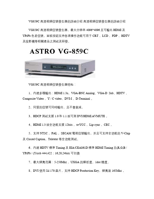
VG859C 高清視頻信號發生器的詳細介紹高清視頻信號發生器的詳細介紹VG859C 高清視頻信號發生器,最大分辨率4096*4096且可輸出HDMI 及YPrPb 色差信號,面板按鈕支持各項操作功能可用于CRT 、LCD 、PDP 、HDTV 及投影機等相關產品之測試及研發。
VG859C 高清視頻信號發生器特點:1、內建多種輸出:HDMI 1.3a,VGA-BNC Analog、VGA-D_Sub、HDTV 、Composite Video 、Y / C video、DVI-I 、D-Terminal 。
2、同質的信號可同時輸出,且不會衰減。
3、HDCP 測試支援1.0和1.1版可測DVI/HDMI.AVMUTE 。
4、HDMI 1.3版全功能支援12bits ,xvYCC ,Lip-sync ,CEC 。
5、支持NTSC ,PAL ,SECAM 電視信號輸出,并且可支持全功能的V-Chip 及Closed Caption,Teletext 等全功能測試。
6、內建HDTV 標準Timing 及EIA/CEA861D標準HDMI Timing且(R,G,B / YPrPb / (Ycrcb 444,422;16,20,24bits 可切換7、最大頻寬范圍:5-250Mhz ,UXGA 的解析度,1dot 精度。
8、DVI 使用Sil 170晶片,支持HDCP Production Key,頻寬達165Mhz 。
9、HDMI 使用SiI 9134晶片,支持HDMI 1.3a規格,頻寬達165Mhz ,TMDS Clock可達225Mhz ,支持EIIA/CEA-861D。
10、標準配備128MB PC Card,具有(16,770,000色全彩自然圖形儲存及輸出之功能,可動態滾動,可測試Video Response。
11、Windows 版軟件為標準配備,可自行編輯所要PATTERN ,且可讀/寫標準EDID 的DDC 資料。
信号发生器的使用条件及操作规程
信号发生器的使用条件及操作规程信号发生器的使用条件信号发生器又称信号源或振荡器,在生产实践和科技领域中有着广泛的应用。
各种波形曲线均可以用三角函数方程式来表示。
能够产生多种波形,如三角波、锯齿波、矩形波(含方波)、正弦波的电路被称为函数信号发生器。
一、信号发生器的分类:1、正弦信号发生器:正弦信号紧要用于测量电路和系统的频率特性、非线性失真、增益及灵敏度等。
按频率覆盖范围分为低频信号发生器、高频信号发生器和微波信号发生器;按输出电平可调整范围和稳定度分为简易信号发生器(即信号源)、标准信号发生器(输出功率能精准地衰减到—100分贝毫瓦以下)和功率信号发生器(输出功率达数十毫瓦以上);按频率更改的方式分为调谐式信号发生器、扫频式信号发生器、程控式信号发生器和频率合成式信号发生器等。
2、高频信号发生器:频率为100千赫~30兆赫的高频、30~300兆赫的甚高频信号发生器。
一般接受LC调谐式振荡器,频率可由调谐电容器的度盘刻度读出。
紧要用途是测量各种接收机的技术指标。
输出信号可用内部或外加的低频正弦信号调幅或调频,使输出载频电压能够衰减到1微伏以下。
3、微波信号发生器:从分米波直到毫米波波段的信号发生器。
信号通常由带分布参数谐振腔的超高频三极管和反射速调管产生,但有渐渐被微波晶体管、场效应管和耿氏二极管等固体器件取代的趋势。
仪器一般靠机械调谐腔体来更改频率,每台可覆盖一个倍频程左右,由腔体耦合出的信号功率一般可达10毫瓦以上。
4、扫频和程控信号发生器:扫频信号发生器能够产生幅度恒定、频率在限定范围内作线性变化的信号。
在高频和甚高频段用低频扫描电压或电流掌控振荡回路元件(如变容管或磁芯线圈)来实现扫频振荡;在微波段早期接受电压调谐扫频,用更改返波管螺旋线电极的直流电压来更改振荡频率,后来广泛接受磁调谐扫频,以YIG铁氧体小球作微波固体振荡器的调谐回路,用扫描电流掌控直流磁场更改小球的谐振频率。
扫频信号发生器有自动扫频、手控、程控和远控等工作方式。
轻松使用HDMI:HDMI-VGA和VGA-HDMI转换器

轻松使用HDMI :HDMI-VGA 和VGA-HDMI 转换器作者:Witold Kaczurba 和Brett Li在消费电子市场,电视、投影仪和其它多媒体设备纷纷采用高清多媒体接口(HDMI ®)技术,使得HDMI 成为全球公认的接口。
相信不久之后,所有多媒体设备都需要配备该接口。
HDMI 接口在家庭娱乐中已经广为流行,近来在便携式设备和汽车信息娱乐系统中,它也日渐风行。
实现标准化多媒体接口是竞争高度激烈的消费电子市场的必然要求,上市时间对于该市场而言至关重要。
除了提高市场认可度以外,采用标准接口还能大大改善投影仪、DVD 播放机、高清电视以及不同制造商生产的其它设备之间的兼容性。
然而,在某些工业应用中,从模拟视频向数字视频过渡所需的时间比消费电子市场要长,许多设备尚未采用新的数字方法来发送合成音视频数据。
这些设备仍然使用模拟信号作为唯一的视频传输途径,原因可能是特殊市场或应用有特定要求。
例如,对于投影仪,有些客户仍然偏好使用视频图形阵列(VGA)电缆,而其它一些客户则使用音频/视频接收器(AVR)或媒体盒作为集线器,将一条HDMI 电缆连接到电视,而不是一组凌乱且不美观的电缆,如图1所示。
图1. 媒体盒将模拟信号转换为HDMI新使用者可能认为HDMI 是一种相对较复杂的标准,需要经过验证的软件驱动器、互通性和兼容性测试,从而保证一种设备与其它各种设备结合使用时能够正常工作。
这似乎有点难以把握,遇到新技术时常常会发生这种情况。
然而,先进的半导体技术正在解决这些难题,模拟域和数字域均实现了改进,包括通过更高性能的模块来均衡较差的差分信号,以及利用更复杂的算法来减少软件开销和纠正位错误。
本文说明先进的半导体解决方案和灵巧的软件如何帮助实现HDMI 。
两种基本器件——HDMI-VGA (“HDMI2VGA”)和VGA-HDMI (“VGA2HDMI”)转换器——为熟悉视频应用的工程师提供一种简单的模拟视频与数字视频相互转换的方法。
- 1、下载文档前请自行甄别文档内容的完整性,平台不提供额外的编辑、内容补充、找答案等附加服务。
- 2、"仅部分预览"的文档,不可在线预览部分如存在完整性等问题,可反馈申请退款(可完整预览的文档不适用该条件!)。
- 3、如文档侵犯您的权益,请联系客服反馈,我们会尽快为您处理(人工客服工作时间:9:00-18:30)。
(HDMI VGA CVBS)视频信号发生器使用说明书
产品特点:
1,支持(HDMI信号,VGA信号,CVBS信号+音频信号)输出。
2,彩屏显示输出信号,内置锂电池,电容式触摸按键,按键提示音。
3,(香槟金,银灰色)铝合金外壳,迷你机身。
操作说明:
1,长按电源键开机,长触摸按键选择输出模式择输出模式(800*600 HDMI/VGA 输出-1024*768 HDMI/VGA输出-电视机信号输出)
2,选择输出模式后,短触摸按键选择显示模式(红色绿色蓝色黄色紫色白色黑色彩条绿色动画)
3,充电指示灯亮红色时,表示正在充电,充指示灯亮绿色时表示充满电。
使用范围:显示器维修,电视机维修,工厂液晶屏检测等。
产品规格:
输出:HDMI信号/VGA信号/CVBS信号+音频信号
输出信号分辨率:1024*768 800*600 PAL制式720*576
输出模式:红色绿色蓝色黄色紫色白色黑色彩条绿色动画。
输入电压:DC +5V
输入电流:DC +5V 400MA
电池:700MAH
尺寸:长7.5CM*宽7.5CM*2.2CM
重量:0.105KG。