数据交换 S7-1200 - S7-1200 (CE-X17)
干货西门子S7-1200PLC硬件接线图,这个要收藏了

干货西门子S7-1200PLC硬件接线图,这个要收藏了
展开全文
SIMATIC S7-1200紧湊型控制器是一款节省空间的模块化控制器,适合要求简单或高级逻辑、HMI和网络功能的小型自动化系统。
S7-1200设计紧凑、成本低廉且功能强大,是控制小型应用的完美解决方案。
S7-1200的硬件
S7-1200的硬件——CPU 模块
S7-1200的硬件——外部接线图L+、M接24VDC电源1M、2M 是公共端子
S7-1200的硬件信号板SB( signal board)通过信号板可以给CPU 增加I/O,SB连接在CPU的前端。
1、具有4个数字量I/O(2 x DC输入和2 x DC输出)的SB
2、具有1路模拟量输出的SB
①SB上的状态LED
②可拆卸用户接线连接器S7-1200的硬件——信号板SB 1221接线图SB 1221 DI 4X24 VDC,200 kHz
S7-1200的硬件——信号板SB 1222接线图SB 1222 DQ 4X24 VDC,200 kHz
S7-1200的硬件——信号板SB 1223接线图SB 1223 DI 2X24 VDC/DQ 2X24 VDC,200 kHz
S7-1200的硬件——信号板SB 1232 1x模拟量输出接线图
S7-1200的硬件——信号模块SM(signal module)可以使用信号模块给CPU增加附加功能,信号模块连接在CPU右侧
①信号模块的I/O的状态LED
②总线连接器③可拆卸用户接线连接器
来源:网络,如有侵权请联系删除。
西门子S7-1200PLC的认知
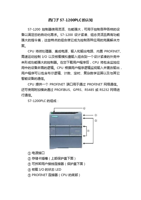
西门子S7-1200PLC的认知S7-1200控制器使用灵活、功能强大,可用于控制各种各样的设备以满足您的自动化需求。
S7-1200 设计紧凑、组态灵活且具有功能强大的指令集,这些特点的组合使它成为控制各种应用的完美解决方案。
CPU将微处理器、集成电源、输入和输出电路、内置PROFINET、高速运动控制I/O 以及板载模拟量输入组合到一个设计紧凑的外壳中来形成功能强大的控制器。
在您下载用户程序后,CPU 将包含监控应用中的设备所需的逻辑。
CPU 根据用户程序逻辑监视输入并更改输出,用户程序可以包含布尔逻辑、计数、定时、复杂数学运算以及与其它智能设备的通信。
CPU 提供一个PROFINET 端口用于通过PROFINET网络通信。
还可使用附加模块通过PROFIBUS、GPRS、RS485或RS232网络进行通信。
S7-1200PLC的组成:① 电源接口② 存储卡插槽(上部保护盖下面)③ 可拆卸用户接线连接器(保护盖下面)④ 板载 I/O的状态 LED⑤ PROFINET连接器(CPU 的底部)S7-1200PLC有多种安全功能可用于保护对CPU和控制程序的访问:● 每个CPU都提供密码保护功能,用户可以通过该功能来组态对CPU功能的访问权限。
● 可以使用“专有技术保护”隐藏特定块中的代码。
● 可以使用复制保护将程序绑定到特定存储卡或 CPU当中。
S7-1200PLC的CPU型号:对于具有继电器输出的 CPU 模块,必须安装数字信号板 (SB),以使用脉冲输出。
每个 CPU 提供专用的 HMI 连接,以支持最多 3 个 HMI 设备。
支持的HMI 总数受组态中HMI面板类型的影响。
例如,可以将最多3 个 SIMATIC 基本面板连接到 CPU,或者最多可以连接两个SIMATIC 精智面板与一个附加基本面板。
不同的CPU型号提供了各种各样的特征和功能,这些特征和功能可帮助用户针对不同的应用创建有效的解决方案。
西门子S7 1200通信教程
集成以太网接口: - 最大3个S7连接 (XPUT/XGET ->仅作为服务器
For internal use only / © Siemens AG 2009. All Rights Reserved. Industry Sector
开放式用户通信 – 概述
概述
开放式用户通信 概述 以太网基础 配置 模块
第 7 章: 通信
For internal use only / © Siemens AG 2009. All Rights Reserved.
概述: 通信接口
概述
开放式用户通信 练习 PtP 通讯
CPU : 以太网 (PROFINET)
PG/OP 通信 开放式用户通信 (T- 功能块)
8个连接 TCP 本地协议 ISO-on-TCP UDP (设计中)
S7-通信
S7-1200 作为服务器 客户端: PUT/GET (设计中)
PROFINET I/O (设计中)
Page 3/47
Communication
For internal use only / © Siemens AG 2009. All Rights Reserved. Industry Sector
练习
PtP 通讯
没有连接管理的功能块
„TCON „
激活以太网连接
„TDISCON“ 断开以太网连接
„TSEND“
发送数据
„TRCV“
接收数据
带有连结管理的功能块
„TSEND_C“ 激活以太网连接并发送数据
„TRCV_C“
激活以太网连接并接收数据
Page 6/47
西门子S7-1200系列PLC全套接线
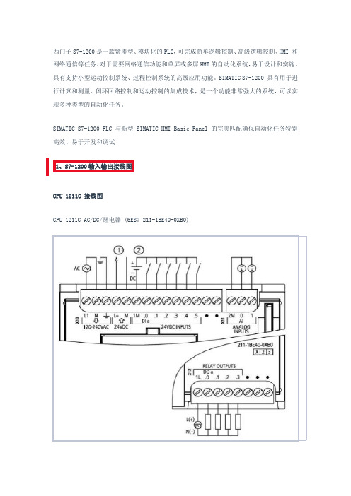
西门子S7-1200是一款紧凑型、模块化的PLC,可完成简单逻辑控制、高级逻辑控制、HMI和网络通信等任务。
对于需要网络通信功能和单屏或多屏HMI的自动化系统,易于设计和实施。
具有支持小型运动控制系统、过程控制系统的高级应用功能。
SIMATIC S7-1200具有用于进行计算和测量、闭环回路控制和运动控制的集成技术,是一个功能非常强大的系统,可以实现多种类型的自动化任务。
SIMATIC S7-1200PLC与新型SIMATIC HMI Basic Panel的完美匹配确保自动化任务特别高效、易于开发和调试1、S7-1200输入输出接线图CPU1211C接线图CPU1211C AC/DC/继电器(6ES7211-1BE40-0XB0)①24VDC传感器电源②对于漏型输入将负载连接到“-”端(如图示);对于源型输入将负载连接到“+”端CPU1211C DC/DC/继电器(6ES7211-1HE40-0XB0)①24VDC传感器电源②对于漏型输入将负载连接到“-”端(如图示);对于源型输入将负载连接到“+”端CPU1211C DC/DC/DC(6ES7211-1AE40-0XB0)①24VDC传感器电源②对于漏型输入将负载连接到“-”端(如图示);对于源型输入将负载连接到“+”端CPU1212C接线图CPU1212C AC/DC/继电器(6ES7212-1BE40-0XB0)①24VDC传感器电源②对于漏型输入将负载连接到“-”端(如图示);对于源型输入将负载连接到“+”端CPU1212C DC/DC/继电器(6ES7212-1HE40-0XB0)①24VDC传感器电源②对于漏型输入将负载连接到“-”端(如图示);对于源型输入将负载连接到“+”端CPU1212C DC/DC/DC(6ES7212-1AE40-0XB0)①24VDC传感器电源②对于漏型输入将负载连接到“-”端(如图示);对于源型输入将负载连接到“+”端CPU1214C接线图CPU1214C AC/DC/继电器(6ES7214-1BG40-0XB0)①24VDC传感器电源②对于漏型输入将负载连接到“-”端(如图示);对于源型输入将负载连接到“+”端CPU1214C DC/DC/继电器(6ES7214-1HG40-0XB0①24VDC传感器电源②对于漏型输入将负载连接到“-”端(如图示);对于源型输入将负载连接到“+”端CPU1214C DC/DC/DC(6ES7214-1AG40-0XB0)①24VDC传感器电源②对于漏型输入将负载连接到“-”端(如图示);对于源型输入将负载连接到“+”端CPU1215C接线图CPU1215C AC/DC/继电器(6ES7215-1BG40-0XB0)①24VDC传感器电源②对于漏型输入将负载连接到“-”端(如图示);对于源型输入将负载连接到“+”端CPU1215C DC/DC/继电器(6ES7215-1HG40-0XB0)①24VDC传感器电源②对于漏型输入将负载连接到“-”端(如图示);对于源型输入将负载连接到“+”端CPU1215C DC/DC/DC(6ES7215-1AG40-0XB0)①24VDC传感器电源②对于漏型输入将负载连接到“-”端(如图示);对于源型输入将负载连接到“+”端CPU1217C接线图CPU1217C DC/DC/DC(6ES7217-1AG40-0XB0)①24VDC传感器电源②对于漏型输入将负载连接到“-”端(如图示);对于源型输入将负载连接到“+”端③5V差分信号输入④5V差分信号输出常见问题1217C的5V差分信号能不能当普通的DI/DO点使用?答:不能。
S7-1200 PLC通信模块介绍
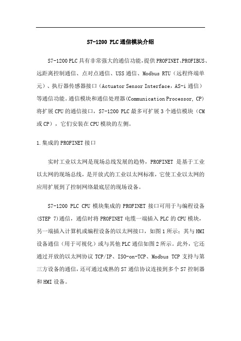
S7-1200 PLC通信模块介绍S7-1200 PLC具有非常强大的通信功能,提供PROFINET、PROFIBUS、远距离控制通信、点对点通信、USS通信、Modbus RTU(远程终端单元)、执行器传感器接口(Actuator Sensor Interface,AS-i通信)等通信功能。
通信模块和通信处理器(Communication Processor, CP)将扩展CPU的通信接口,S7-1200 PLC最多可扩展3个通信模块(CM 或CP),它们安装在CPU模块的左侧。
1.集成的PROFINET接口实时工业以太网是现场总线发展的趋势,PROFINET是基于工业以太网的现场总线,是开放式的工业以太网标准,它使工业以太网的应用扩展到了控制网络最底层的现场设备。
S7-1200 PLC CPU模块集成的PROFINET接口可用于与编程设备(STEP 7)通信,通信时将PROFINET电缆一端插入PLC的CPU模块,另一端插入计算机或编程设备的以太网接口,如图1所示;其与HMI 设备通信(用于可视化)或与其他PLC通信如图2所示。
此外,它还通过开放的以太网协议TCP/IP、ISO-on-TCP、Modbus TCP支持与第三方设备的通信,还可通过成熟的S7通信协议连接到多个S7控制器和HMI设备。
图1 S7-1200 PLC与编程设备通信图2 S7-1200 PLC与HMI、PLC的通信S7-1200 PROFINET接口由一个RJ45连接器组成。
该连接器具有自动交叉网线功能,因此一个标准或是交叉的以太网线都可以用于该接口,支持最多23个以太网连接,数据传输速率达10/100Mbit/s。
CSM 1277是一个4端口的紧凑型交换机,用户可以通过它将S7-1200 PLC连接到最多3个附加设备,以便轻松组建网络。
2.PROFIBUS通信与通信模块PROFIBUS是目前国际上通用的现场总线标准之一。
【图文】西门子S7-1200通讯大全

【图文】西门子S7-1200通讯大全【导读】西门子S7-1200小型可编程控制器充分满足于中小型自动化的系统需求。
产品考虑了系统、人机界面和软件的无缝整合和高效协调的需求。
虽然西门子公司将其定位为低端的离散自动化系统和独立自动化系统中使用的小型控制器模块,但是其强大的通讯功能还是让人爱不释手,下面我们就一起来汇总S7-1200各种通讯的硬件模块及技术参数,方便我们在实际应用中选择正确的通讯方式。
从STEP 7 Basic/Professional V13 SP1 开始,在编程指令,"选件包"中集成了SIMATIC Ident 配置文件和Ident 指令块,使用TIA Portal 进行组态与编程的 S7-1200/1500 可以使用这些指令对工业识别系统进行操作。
S7-1200 可以使用 RF120C 通信模块,实现与西门子工业识别系统的通信。
本文介绍通过S7-1200 CPU 和RF120C ,使用 Ident 指令块,实现对 RF200 进行读、写操作。
(1)主要硬件设备:CPU1215C:6ES7 215-1AG40-0AB0RF120C:6GT2 002-0LA00RF260R:6GT2 821-6AC10MDS D100:6GT2 600-0AD10RF260R 到 RF120C 连接电缆(2m):6GT2 091-4LH20(2)软件环境:TIA Portal V13 SP1 Update 4(3)系统配置:S7-1200 CPU1215C 通过 RF120C 通信模块,连接 RF260R 读写头,在TIA Portal V13 SP1 Update4 软件环境下,使用SIMATIC Ident 指令块对数据载体(MDS D100)进行读写操作。
系统配置,如图1所示:关于S7-1200各种通讯的详细步骤和实例将陆续推出!大家都在看【视频】德国工程师是如何制作PLC柜的?【视频】德国威图电气柜是如何生产出的?【视频】德国工程师的办公环境是怎样的?【视频】PROFINET为何比PROFIBUS更牛?设为星标不见不散有时我们关注的公众号比较多,可能会错过一些自己喜欢的消息,我们可以给公众号加星标来解决这个问题。
Siemens S7-1200 PLC 安装指南说明书
T ABLE OF CONTENTS How To Use This User Guide (iv)Assumptions (iv)Contents of This Manual (iv)Installation Process Overview (v)Installation Preparation (v)Chapter 1—Introduction (1)Chapter Objective (1)Product Description (1)Features (1)Following Option (SXF) (2)Chapter 2—Getting Started (3)Chapter Objectives (3)What You Should Have (3)High and Low Power Drives (3)Chapter 3—Installation (9)Chapter Objectives (9)Installation Precautions (9)Environmental Considerations (9)Wiring Considerations (9)Preventing Electrical Noise Problems (10)Installation Overview (10)Series vs. Parallel Motor Wiring (11)Motor Configurations (12)Configuration of the Drive (19)Fan Connection (20)I/O Connections (20)OPTO1 (24)CW and CCW Limits (25)OPTO2 (25)O1—O4 Outputs (27)Encoder Connections (28)Incremental Encoder Connection (29)Absolute Encoder Connection (29)AC Power Connection (30)Transformers (30)Transformer Specifications (30)Power Ratings (31)Installation Verification (33)Input Conventions (33)Output Conventions (33)Fault Output Convention (34)Motor Test (34)Incremental Encoder Test (34)Absolute Encoder Test (35)Drive Mounting (35)Minimum Width (35)Minimum Depth (35)Attaching the Load (37)Contents iCouplings (37)Tuning (38)Resonance (38)Mid-Range Instability (38)Tuning Procedures (38)Motor Waveforms (40)Anti-Resonance (40)Chapter 4—Application Design (41)Chapter Objectives (41)Motion Profile Application Considerations (41)Preset Mode Moves (42)Incremental Mode Preset Moves (42)Absolute Mode Preset Moves (42)Continuous Mode Moves (43)Closed Loop Operation (44)Setting Encoder Resolution (45)Encoder Step Mode (45)Motion Programs and Sequences (56)Sequence Commands (56)Creating and Executing Sequences (58)Subroutines (59)Sequence Debugging Tools (63)High-Level Programming Tools (67)Complex Branching and Looping (70)Conditionals (71)Error Flag (75)Branching Using Variables and Boolean Logic (76)Motion Profiling Mode—On-the-Fly Changes (77)Interfacing to the SX (81)Programmable Inputs and Outputs (81)PLC Operation (94)Rotary vs. Linear Indexers (97)Chapter 5—SXF Follower (99)Chapter Objectives (99)What is Following? (99)Types of Following (100)Velocity Following (100)Position and Velocity Following (103)Recede and Advance While Following (115)Synchronization (132)Other Following Features (135)Following Equation and Command Summary (137)Chapter 6—Hardware Reference (143)Chapter Objectives (143)Environmental Specifications (143)Drive Electrical Specifications (143)I/O Electrical Specifications (144)Motor Electrical Specifications (147)Operational Specifications (147)Motor Current & Torque (148)Drive Dimensions (149)Motor Dimensions (150)DIP Switch Summary (152)Non-Compumotor—Drive/Motor Connection (155)Wiring Configurations.............................................................................................................................155, 156 Terminal Connections. (157)Non-Compumotor Motors—Setting Motor Current (158)Motor Performance Specifications (158)ii SX/SXF Indexer/Driver User GuideChapter 7—Maintenance & Troubleshooting (161)Chapter Objectives (161)Maintenance (161)Battery Maintenance (161)Drive Maintenance (161)Motor Maintenance (162)Common Problems and Solutions (163)Software Debugging Tips (165)Returning the System (167)Appendices (169)Command Listing (169)SX Example Programs (171)Appendix C—LVD Installation Instructions (175)Complying with the Low Voltage Directive (LVD) (175)Additional Installation Procedures for LVD Compliance (175)Table of Graphic Symbols and Warnings (177)Index (179)Contents iiiHow To Use This User GuideThis user guide is designed to help you install, develop, and maintain your system. Each chapterbegins with a list of specific objectives that should be met after you have read the chapter. Thissection is intended to help you find and use the information in this user guide. AssumptionsThis user guide assumes that you have the skills or fundamental understanding of the followinginformation.t Basic electronics concepts (voltage, switches, current, etc.)t Basic motion control concepts (torque, velocity, distance, force, etc.)Contents of This ManualThis user guide contains the following information.Chapter 1:IntroductionThis chapter provides a description of the product and a brief account of its specific features.Chapter 2:Getting StartedThis chapter contains a detailed list of items you should have received with your SX shipment. Itwill help you to become familiar with the system and ensure that each component functions properly.Chapter 3:InstallationThis chapter provides instructions for you to properly mount the system and make all electricalconnections. Upon completion of this chapter, your system should be completely installed and readyto perform basic operations. Tuning considerations and procedures are also provided.Chapter 4:Application DesignThis chapter will help you customize the system to meet your application’s needs. Importantapplication considerations are discussed. Sample applications are provided.Chapter 5:SXF FollowerThis chapter explains the SXF Following function and the SXF’s capability to support absolute andincremental encoders.Chapter 6:Hardware ReferenceThis chapter contains information on system specifications (electrical, dimensions, and perfor-mance). It may be used as a quick-reference tool for proper switch settings and connections.Chapter 7:TroubleshootingThis chapter contains information on identifying and resolving system problems.iv SX/SXF Indexer/Driver User GuideInstallation Process OverviewTo ensure trouble-free operation, pay special attention to the environment in which the SX equip-ment will operate, the layout and mounting, and the wiring and grounding practices used. Theserecommendations are intended to help you easily and safely integrate SX equipment into yourmanufacturing facility. Industrial environments often contain conditions that may adversely affectsolid-state equipment. Electrical noise or atmospheric contamination, may also affect the SXSystem.Developing Your ApplicationBefore you attempt to develop and implement your application, there are several issues that youshould consider and address.Recognize and clarify the requirements of your application. Clearly define what you expect the system todo.Assess your resources and limitations. This will help you find the most efficient and effective means ofdeveloping and implementing your application (hardware and software).Follow the guidelines and instructions outlined in this user guide. Do not skip any steps or procedures.Proper installation and implementation can only be ensured if all procedures are completed in the propersequence.Installation PreparationBefore you attempt to install this product, you should complete the following steps:Review this entire user guide. Become familiar with the user guide’s contents so that you can quickly findthe information you need.Develop a basic understanding of all system components, their functions, and interrelationships.Complete the basic system configuration and wiring instructions (in a simulated environment, not apermanent installation) provided in Chapter 2, Getting Started.Perform as many basic functions as you can with the preliminary configuration. You can only perform thistask if you have reviewed the entire user guide. You should try to simulate the task(s) that you expect toperform when you permanently install your application (however, do not attach a load at this time). Thiswill give you a realistic preview of what to expect from the complete configuration.After you have tested all of the system’s functions and used or become familiar with tll of the system’sfeatures, carefully read Chapter 3, Installation.After you have read Chapter 3 and clearly understand what must be done to properly install the system,you should begin the installation process. Do not deviate from the sequence or installation methodsprovided.Before you begin to customize your system, check all of the systems functions and features to ensure thatyou have completed the installation process correctly.The successful completion of these steps will prevent subsequent performance problems and allowyou to isolate and resolve any potential system difficulties before they affect your system’soperation.ConventionsTo help you understand and use this user guide effectively, the conventions used throughout this userguide are explained in this section.CommandsAll commands that you are instructed to enter are shown in capital letters. The symbol >, is the SXcommand prompt. The command is displayed in boldface. A delimiter (space or carriage return) isrequired after each command. A description is provided next to each command example.Command Description>MR Sets motor resolution to 25,000 steps/revThe system ignores command syntax that is not within the valid range for a specific command. A ?prompt will be returned by the drive when the last command entered was not understood, or aparameter limit was exceeded.Contents vMotorsS Series and SX Series motors are one in the same (interchangeable terms).Warnings & CautionsWarning and caution notes alert you to possible dangers that may occur if you do not follow instruc-tions correctly. Situations that may cause bodily injury are present as warnings. Situations that maycause system damage are presented as cautions. These notes will appear in bold face and the wordwarning or caution will be centered and in all capital letters. Refer to the examples shown below:WARNINGDo not touch the motor immediately after it has been in use for an extended period of time. The motormay be hot.CAUTIONSystem damage will occur if you power up the system improperly.Related Publicationst Current Parker Compumotor Motion Control Catalogt SX Indexer/Drive Software Reference Guidevi SX/SXF Indexer/Driver User Guide。
S7-1200的指令
【例3-2】 用接通延时定时器设计周期和占空比可调的振荡电路。 图3-22中的串联电路接通后,定时器T5的IN输入信号为1状态,开始定时。 2s后定时时间到,它的Q输出使定时器T6开始定时,同时Q0.7的线圈通电。 3s后T6的定时时间到,它的输出“T6”.Q的常闭触点断开,使T5的IN输入电 路断开,其Q输出变为0状态,使Q0.7和定时器T6的Q输出也变为0状态。下一 个扫描周期因为“T6”.Q的常闭触点接通,T5又从预设值开始定时。Q0.7的 线圈将这样周期性地通电和断电,直到串联电路断开。Q0.7线圈通电和断电 的时间分别等于T6和T5的预设值。
6.置位/复位触发器与复位/置位触发器 SR方框是置位/复位(复位优先)触发器,在置位(S)和复位(R1)信号 同时为1时,方框上的输出位M7.2被复位为0。可选的输出Q反映了M7.2的状态。 RS方框是复位/置位(置位优先)触发器,在置位(S1)和复位(R)信号 同时为1时,方框上的M7.6为置位为1。可选的输出Q反映了M7.6的状态。
5.置位位域指令与复位位域指令 “置位位域”指令SET_BF将指定的地址开始的连续的若干个位地址置位, “复位位域”指令RESET_BF将指定的地址开始的连续的若干个位地址复位。
7.扫描操作数信号边沿的指令 中间有P的触点的名称为“扫描操作数的信号上升沿”,在I0.6的上升沿, 该触点接通一个扫描周期。M4.3为边沿存储位,用来存储上一次扫描循环时 I0.6的状态。通过比较I0.6前后两次循环的状态,来检测信号的边沿。边沿存 储位的地址只能在程序中使用一次。不能用代码块的临时局部数据或I/O变量 来作边沿存储位。 中间有N的触点的名称为“扫描操作数的信号下降沿”,在M4.4的下降沿, RESET_BF的线圈“通电”一个扫描周期。该触点下面的M4.5为边沿存储位。
(电气控制与PLC)第四章S7-1200PLC的硬件
S7-1200 的硬件-CPU模块
24V DC 电源输出
PLC的电源
数字/模拟输入 继电器输出
P14 图2-2 输出端口的外部电源
2020/10/4
福州大学电气工程与自动化学院
24
S7-1200 的硬件-CPU模块
P14 图2-3
晶体管输出
2020/10/4
福州大学电气工程与自动化学院
25
S7-1200 的硬件-CPU模块
板载 I/O 的状态LED
PROFINET 连接器(CPU 的底部)
2020/10/4
福州大学电气工程与自动化学院
18
S7-200 硬件内部结构
S7-200 I/O接口
CPU
RAM
S7-1200
ROM
2020/10/4
LED 指示灯
通信接口
福州大学电气工程与自动化学院
I/O扩展接口
19
S7-1200 的硬件-CPU模块
为什么需要工业以太网/现场总线?
➢ 设备数量/复杂度++
➢ 设备数据量++ ➢ 部署空间++
• 管理维护困难
2020/10/4
福州大学电气工程与自动化学院
38
S7-1200 —通信接口
PROFINET是基于工业以太网的现场总线,是开放式的工业以 太网标准,它使工业以太网的应用扩展到了控制网络最底层的 现场设备。
❖ 西门子公司是全球电子电气工程领域 的领先企业,1847年由维尔纳·冯· 西门子建立,总部位于德国慕尼黑。
❖ 西门子在全球拥有约405,000名员 工,业务遍布190个国家。在中国拥 有超过30,000名员工,建立了17 个研发中心、73家运营企业和65个 地区办事处
S7-1200 和 S7-1200 之间 UDP 通信
S7-1200 和S7-1200 之间UDP 通信S7-1200 与S7-1200 之间的以太网通信可以通过UDP 协议来实现,使用的通信指令是在双方CPU 调用T-block ( TCON, TDISCON, TUSEND, TURCV) 指令来实现。
通信方式为双边通信,因此TUSEND 和TURCV 必须成对出现。
硬件和软件需求及所完成的通信任务硬件:①S7-1200 CPU②PC (带以太网卡)③TP电缆(以太网电缆)软件:STEP7 V11 or Higher(只有STEP7 V11才有此功能)所完成的通信任务:①将PLC_1 的通信数据区DB3 块中的100 个字节的数据发送到PLC_2 的接收数据区DB4 块中。
②将PLC_2 的通信数据区DB3 块中的100 个字节的数据发送到PLC_1 的接收数据区DB4 块中。
通信的编程,连接参数及通信参数的配置1. 打开STEP7 v11 软件并新建项目在STEP7 v11的“Portal View” 中选择“Create new project” 创建一个新项目2. 添加硬件并命名PLC然后进入“Project view”,在“Project tree” 下双击“Add new device”,在对话框中选择所使用的S7-1200 CPU添加到机架上,命名为PLC_1,如图1所示。
同样方法再添加通信伙伴的S7-1200 CPU ,命名为PLC_2。
图1. 添加新设备为了编程方便,使用CPU 属性中定义的时钟位,定义方法如下:在“Project tree” > “PLC_1” > “Device configuration” 中,选中CPU ,然后在下面的属性窗口中,“Properties” > “System and clock memory” 下,将系统位定义在MB1,时钟位定义在MB0,如图2所示。
时钟位我们主要使用M0.3,它是以2Hz 的速率在0和1之间切换的一个位,可以使用它去自动激活发送任务。
- 1、下载文档前请自行甄别文档内容的完整性,平台不提供额外的编辑、内容补充、找答案等附加服务。
- 2、"仅部分预览"的文档,不可在线预览部分如存在完整性等问题,可反馈申请退款(可完整预览的文档不适用该条件!)。
- 3、如文档侵犯您的权益,请联系客服反馈,我们会尽快为您处理(人工客服工作时间:9:00-18:30)。
CoverEthernet Communication: Data Exchange S7-1200 <-> S7-1200
S7-1200 Configuration Example X17 y September 2010
Applications & Tools Answers for industry. Warranty, Liability and Support Ethernet Communication: Data Exchange S7-1200 <-> S7-1200 V1.2, Entry ID: 39040038 2
Warranty, Liability and Support Note The application examples are not binding and do not claim to be complete regarding configuration, equipment and any eventuality. The application examples do not represent customer-specific solutions. They are only intended to provide support for typical applications. You are responsible for ensuring that the described products are used correctly. These application examples do not relieve you of the responsibility to use sound practices in application, installation, operation and maintenance. When using these Application Examples, you recognize that we cannot be made liable for any damage/claims beyond the liability clause described. We reserve the right to make changes to these Application Examples at any time without prior notice. If there are any deviations between the recommendations provided in this application example and other Siemens publications – e.g. Catalogs – the contents of the other documents have priority.
We accept no liability for information contained in this document. Any claims against us – based on whatever legal reason – resulting from the use of the examples, information, programs, engineering and performance data etc., described in this Application Example shall be excluded. Such an exclusion shall not apply in the case of mandatory liability, e.g. under the German Product Liability Act (“Produkthaftungsgesetz”), in case of intent, gross negligence, or injury of life, body or health, guarantee for the quality of a product, fraudulent concealment of a deficiency or breach of a condition which goes to the root of the contract (“wesentliche Vertragspflichten”). However, claims arising from a breach of a condition which goes to the root of the contract shall be limited to the foreseeable damage which is intrinsic to the contract, unless caused by intent or gross negligence or based on mandatory liability for injury of life, body or health. The above provisions do not imply a change in the burden of proof to your detriment.
It is not permissible to transfer or copy these Application Examples or excerpts thereof without express authorization from Siemens Industry Sector.
If you have any questions regarding this document, please send us an e-mail to the following address:
online-support.automation@siemens.com Table of Contents
Ethernet Communication: Data Exchange S7-1200 <-> S7-1200 V1.2, Entry ID: 39040038 3
Table of Contents Warranty, Liability and Support..................................................................................2 1 Automation Task................................................................................................4 1.1 Tasks....................................................................................................4 1.2 Setup....................................................................................................5 List of components...............................................................................5
2 Automation Solution.........................................................................................7 2.1 Wiring diagram.....................................................................................8 2.2 Program structure.................................................................................9 2.2.1 Block structure of the master...............................................................9 2.2.2 Block structure of the slave................................................................11 2.3 Used blocks........................................................................................12 2.3.1 Master.................................................................................................12 2.3.2 Slave...................................................................................................15 2.3.3 Data consistency................................................................................15 2.3.4 Expanding the slave number..............................................................17 2.4 Program sequence.............................................................................19 2.4.1 Program sequence in the master controller.......................................19 2.4.2 Program sequence in the slave controller..........................................21