球阀说明书
球阀—产品使用说明书

Ball valves球阀使用说明书Ball Valve Operating Manual浙江石化阀门有限公司Zhejiang Petrochemical Valve Co., Ltd.二O一一年 Year 2011一用途Application球阀是一种管线阀门产品,用于接通或截断管路中的介质。
一般是处于全开或全关状态,在微开状态下可作流量的调节使用。
广泛适用于工况条件下水、气、油品等介质的各种管路中。
Ball valve is pipeline valve, used for connecting or cutting off medium in the pipelines. Normally it is at the state of opening or closing. And it couldfunction as regulating the flow when it is at the state of slightly open. It isused on the pipeline such as water, gas, oil etc.二性能规范 Performance Specification压力等级: Class150; Class300; Class600;Pressure: Class150; Class300; Class600;公称尺寸:NPS 2 ~NPS24;Nominal Size: NPS 2 ~NPS24阀体材料: ASTM A216 WCB; ASTM A351 CF8;Body Material:ASTM A216 WCB;ASTM A351 CF8;产品的设计、制造按API6D的规定;检查试验按API6D的规定;法兰连接尺寸按 ASME 的规定;结构长度按API6D的规定;Designed and manufactured according to API6D; Inspected and tested accordingto API6D;Flange ends according to ASME ; Face to face according to API 6D适用介质:水、蒸汽、油品等。
Belimo LR24A-SR 调节旋钮驱动球阀电机说明书

LR24A-SRModulating rotary actuator for ball valves• Torque motor 5 Nm• Nominal voltage AC/DC 24 V• Control modulating 2...10 V• Position feedback 2...10 VTechnical dataElectrical data Nominal voltage AC/DC 24 VNominal voltage frequency50/60 HzNominal voltage range AC 19.2...28.8 V / DC 19.2...28.8 VPower consumption in operation 1.5 WPower consumption in rest position0.4 WPower consumption for wire sizing 3 VAConnection supply / control Cable 1 m, 4x 0.75 mm²Parallel operation Yes (note the performance data)Functional data Torque motor5 NmOperating range Y 2...10 VInput impedance100 kΩPosition feedback U 2...10 VPosition feedback U note Max. 1 mAPosition accuracy±5%Manual override with push-button, can be lockedRunning time motor90 s / 90°Sound power level, motor35 dB(A)Position indication Mechanical, pluggableSafety data Protection class IEC/EN III, Safety Extra-Low Voltage (SELV)Power source UL Class 2 SupplyDegree of protection IEC/EN IP54Degree of protection NEMA/UL NEMA 2Enclosure UL Enclosure Type 2EMC CE according to 2014/30/EUCertification IEC/EN IEC/EN 60730-1 and IEC/EN 60730-2-14UL Approval cULus according to UL60730-1A, UL60730-2-14and CAN/CSA E60730-1The UL marking on the actuator depends onthe production site, the device is UL-compliantin any caseType of action Type 1Rated impulse voltage supply / control0.8 kVPollution degree3Ambient humidity Max. 95% RH, non-condensingAmbient temperature-30...50°C [-22...122°F]Storage temperature-40...80°C [-40...176°F]LR24A-SRSafety dataServicing maintenance-free WeightWeight 0.48 kgTechnical data•••••••Safety notesThis device has been designed for use in stationary heating, ventilation and air-conditioning systems and must not be used outside the specified field of application, especially in aircraft or in any other airborne means of transport.Outdoor application: only possible in case that no (sea) water, snow, ice, insolation or aggressive gases interfere directly with the device and that it is ensured that the ambient conditions remain within the thresholds according to the data sheet at any time.Only authorised specialists may carry out installation. All applicable legal or institutional installation regulations must be complied with during installation.The switch for changing the direction of rotation may only be operated by authorisedspecialists. The direction of rotation must not in particular be reversed in a frost protection circuit.The device may only be opened at the manufacturer's site. It does not contain any parts that can be replaced or repaired by the user.Cables must not be removed from the device.The device contains electrical and electronic components and must not be disposed of as household refuse. All locally valid regulations and requirements must be observed.Operating modeSimple direct mountingManual overrideAdjustable angle of rotation High functional reliabilityProduct featuresThe actuator is connected with a standard control signal of 0...10 V and drives to the position defined by the control signal. Measuring voltage U serves for the electrical display of the valve position 0.5...100% and as control signal for other actuators.Straightforward direct mounting on the ball valve with only one central screw. The assembly tool is integrated in the plug-in position indication. The mounting orientation in relation to the ball valve can be selected in 90° steps.Manual override with push-button possible (the gear train is disengaged for as long as the button is pressed or remains locked).Adjustable angle of rotation with mechanical end stops.The actuator is overload protected, requires no limit switches and automatically stops when the end stop is reached.AccessoriesElectrical accessoriesDescriptionType Auxiliary switch 1x SPDT add-on S1A Auxiliary switch 2x SPDT add-onS2A Feedback potentiometer 140 Ω add-on P140A Feedback potentiometer 200 Ω add-on P200A Feedback potentiometer 500 Ω add-on P500A Feedback potentiometer 1 kΩ add-on P1000A Feedback potentiometer 2.8 kΩ add-on P2800A Feedback potentiometer 5 kΩ add-on P5000A Feedback potentiometer 10 kΩ add-onP10000ALR24A-SRWire colours:1 = black 2 = red 3 = white 5 = orangeElectrical installationSupply from isolating transformer.Parallel connection of other actuators possible. Observe the performance data.Direction of rotation switch is covered. Factory setting: Direction of rotation Y2.Wiring diagramsAC/DC 24 V, modulatingOverride control (frost protectioncircuit)DimensionsFurther documentation• The complete product range for water applications• Data sheets for ball valves• Installation instructions for actuators and/or ball valves• General notes for project planning。
世伟洛克 40G,40,60,83系列 和 AFS 球阀 说明书
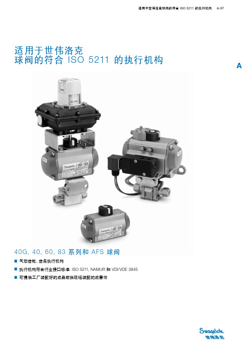
适用于世伟洛克球阀的符合 ISO 5211 的执行机构 A-97A40G, 40, 60, 83 系列和 AFS 球阀■ 气动齿轮、齿条执行机构■ 执行机构符合行业接口标准:ISO 5211, NAMUR 和 VDI/VDE 3845■ 可提供工厂装配好的成品或供现场装配的成套件适用于世伟洛克球阀的符合 ISO 5211 的执行机构A-98 球阀A符合 ISO 5211 的世伟洛克齿条和齿轮气动执行机构适用于一般应用。
提供直通阀和角型阀用弹簧回程和双作用模式的产品。
世伟洛克可提供符合 ISO 5211、NAMUR 和 VDI/VDE 3845 接口标准的带全部执行机构的球阀组件、包括阀门、执行机构、传感器、支架成套件和电磁阀。
本产品目录所列阀门执行机构组件的设计条件是:■ 最高阀门压力■ 环境温度 (10 到 37°C [50 到100°F])■ 设计余量为计算操作扭矩的 20%。
欲获得关于阀门操作扭矩计算的更多信息、请参阅世伟洛克带执行机构的球阀选型指南、符合 ISO 5211 的执行机构安装支架成套件、P A-105。
执行机构工作额定值最大的执行机构压力是 116 psig (8 .0 bar)。
证书对于工厂装配的符合 ISO 5211 的世伟洛克执行机构、可在订单报价时要求提供 ATEX 认证。
现场装配不提供 ATEX 认证。
执行机构结构材料还可以提供更多材料。
请联系您的授权世伟洛克代表。
执行机构安装支架阀门阀门接地弹簧电磁阀安装支架位置指示器接头阀杆螺母锁定片固定螺钉接头面板螺母40G, 40, 83, H83 系列AFS 球阀60 系列 4 螺栓铸造不锈钢墙壁安装支架六角螺栓有头螺钉六角 螺母锁紧垫圈符合 ISO 5211 标准的气动执行机构适用于世伟洛克球阀的符合 ISO 5211 的执行机构 A-99A40G 和 40 系列阀门关于阀门特点、结构材料和技术数据、请参阅世伟洛克产品目录一体式仪表球阀—40G系列和 40 系列, P A-3。
苏州纽威阀门 BS 系列电动固定球阀 说明书
文件号: NWD 0406版本号: 2006BS系列电动固定球阀使用说明书受控本非受控本编制日期 .审核日期 .批准日期 .苏州纽威阀门有限公司NEWAY VALVE(SUZHOU)CO., LTD地址:中国江苏省苏州新区湘江路999号,215129电话:0086-512-6665 1365传真:0086-512-6665 1360E-mail:***************.cnWEB: 文件修改记录版本号修改页/节修改说明实施日期更改单号2006 新版 2006-3-17目录1.前言 (3)2. 欧共体关于承压设备和防爆指令对健康和安全的基本要求 (3)3. 用途和技术性能 (4)4. 阀门结构 (5)5. 运输和保管 (8)6. 安装 (8)7. 移动 (9)8. 拆卸程序 (9)9. 重装程序 (10)10.阀门操作和维护 (12)11.电动执行器的使用说明 (14)12.故障及维修 (16)13.质量保证及服务 (17)1.前言1.1 感谢您选择纽威阀门。
作为一种承压设备,当阀门用于输送流体及易燃易爆气体时,由于泄露或使用不当往往存在一些安全隐患,从安全角度考虑,用户使用前,应仔细阅读本说明书,了解纽威在设计和制造过程中所采取的安全措施,以防患于未然。
2. 欧共体关于承压设备和防爆指令对健康和安全的基本要求2.1 纽威的设计理念—球阀作为一种标准产品来设计,由于它的范围较广所以并不考虑每一个细节的工作条件。
—球阀设计参照API 6D,阀门强度参照ASME B16.34 压力—温度额定值。
—阀门密封材料应根据介质对材料的抗腐蚀性和耐磨损的要求而选择,参照API 6D。
—阀门设计时应有防静电装置及防火结构,放火实验设备符合API 607及API 6FA 规范,并已通过英国的劳氏船级社认证。
—阀门不含轻金属(例如镁),各零部件通过相互接触形成导电通路,通过管道流向大地,以防止静电积累。
—阀门根据它的型号、扭矩、及操作要求等,配置合适的电动驱动装置。
球阀使用说明书
2、阀门两端连接采用法兰结构或长焊接端,浮动球阀阀体和阀盖
连接处密封采用 PTFE 垫片。
3、阀杆采用有防飞出功能的下装结构。
4、扁式阀杆头的设计能让装配的手柄始终与流体通道平行。装配
中,应避免手柄未达到预定位置。
五、阀门运输和保管
1、阀门运输 (1)在运输过程中,应将阀门用纸箱或木箱包装。如纸箱或木箱 无法包装阀门时,应用托盘将阀门固定好,做防尘防水处理。 (2)在装载阀门时,不要让传动装置承受任何外力。 (3)避免装载设备时超载,货物摆放要宽松,避免阀门受撞击。 (4)所有的阀门搬运都应该很小心,对于大口径的阀门应该用起 吊设备。 2、阀门保管
片,可以作为修理和维护的备用零件进行订购。 8、分解及再装配时必须小心防止损伤零件的密封面,特别是非金 属零件,取出 O 型圈时宜使用专用工具。 9、分解下来的单个零件可以用浸洗方式清洗。尚留有未分解下来 的非金属件的金属件可采用干净的细洁的浸渍有清洗剂的绸布 (为避免纤维脱落粘附在零件上)擦洗。清洗时须去除一切粘附 在壁面上的油脂、污垢、积胶、灰尘等。 10、非金属零件清洗后应立即从清洗剂中取出,不得长时间浸泡。 11、清洗后需待被洗壁面清洗剂挥发后(可用未浸清洗剂的绸布 擦)进行装配,但不得长时间搁置,否则会生锈、被灰尘污染。 12、使用润滑脂润滑。润滑脂应与阀金属材料、橡胶件、塑料件 及工作介质均相容。在密封件安装槽的表面上涂一薄层润滑脂, 在橡胶密封件上涂一薄层润滑脂,阀杆的密封面及摩擦面上涂一 薄层润滑脂。
高压水密封实验压力
1.76MPa
低压气密封实验压力
0.6MPa
适用温度℃
-29~200
三、工作原理
球阀的主要功能是切断或接通管道中的流体。当手动或其它
福建南平思特斯-ZBQF电动球阀使用说明书(SITES)

自保持电动球阀使用说明书一、概述:自保持电动球阀主要是由阀体和驱动机构组成,用以远程控制管道介质的流通与中断,并能够准确发出阀位信号,易于远程监控,并能现场监测。
适用于空气、油、水等无强腐蚀性的流体,广泛应用于电力、石化、冶金等部门,二、特点:1、本阀采用球面密封结构、无内漏、耐压和工作压力等级更高。
2、球阀驱动采用星行减速执行机构,可满足水电站潮湿环境要求。
3、阀位置有两者机械显示和开关接点输出。
4、介质:油、水、无腐蚀性气体,对介质清洁度不作严格要求。
5、额定压力:1.6MPa,2.5Mpa,4.0MPa,6.4MPa、10MPa6、电源电压:DC220V,AC220V,AC380V7、公称通径:Φ15~Φ2008、环境温度:0~45℃;介质温度:≤150℃;相对湿度:≤95%RH。
9、连接方式:法兰连接。
10、能够调整密封间隙。
11、阀位开关输出的阀位置为开关量信号。
可现场观察阀开关位置,红点表示阀处于关位置。
三、工作原理:(见外形结构图及电气接线图)当阀处于全关位置,阀位指示输出阀全关信号,当需要切换介质回路时,驱动机构开阀信号端得电带动球阀阀芯转动,阀芯转到位后,电源自动切断,阀位输出阀全开信号,介质直通。
当需要关断时,驱动机构关阀信号端得电带动球阀阀芯转动,阀芯转到位后,电源自动切断,阀位输出关阀信号,介质被截断,完成一个工作循环。
过程中,应经常补充润滑油脂。
建议每年拆洗换油一次(指24小时连续工运转。
附:减速机使用说明书一、使用条件1、本系列减速机可以在室内或室外各种场合使用,环境温度可在-15℃~+40℃范围内使用。
2、本系列减速机允许连续工作,同时允许正反两个方向运转。
3、本系列减速机输入额定转速为2000转/分,不宜过高。
本系列减速机允许任何方向和角度位置安装。
4、本系列减速机输出轴不宜承受较大的轴向力,在有较大轴向力场合使用时,应采取其他卸荷措施。
二、安装注意事项1、本系列减速机在安装时,应核准减速机的安装中心线标高,水平度及相关联接部件的位置尺寸,不允许超过联接件所允许的范围。
球阀设计计算说明书
设计计算说明书名称:O型球阀(浮动、硬密封)型号:口径:3”编制:审核:批准:日期:_ 年月日_目录1.计算项目列表2.设计参数3.阀门主要零部件的设计计算3.1端部连接和结构长度3.2球阀阀体壁厚的计算3.3球阀阀体法兰的设计3.4球阀阀杆强度的计算3.5填料压盖的强度计算3.6球阀用弹性元件的计算3.7球体直径的确定3.8球阀密封力的计算引用资料1.计算项目列表:(1)、端部连接和结构长度(2)、球阀阀体壁厚的计算(3)、球阀阀体法兰的设计(4)、球阀阀杆强度的计算(5)、填料压盖的强度计算(6)、球阀用弹性元件的计算(7)、球体直径的确定(8)、球阀密封力的计算2.设计参数工作压力:300Lb(5MPa)工作温度:-29—425工作介质:液体、气体、蒸汽公称通径:4”3.阀门主要零部件的设计计算由于工作温度在-29-425度,所以选用主体材质为ASTM A216 WCB,查资料【1】P25表2-1.13.1端部连接和结构长度端部连接,包括法兰式、对焊端、承插焊、螺纹端,查找相应标准;结构长度,包括法兰连接、螺纹、焊接,查找相应标准3.2球阀阀体壁厚的计算中低压金属球阀阀体的强度计算通常采用薄壁容器的计算方式:也可根据经验值取C=3~6mm参考资料【2】p298-299资料【2】p301,表6-7。
PN50,DN80时,壁厚选7.1mm,取9mm。
3.3球阀阀体法兰的设计3.3.1法兰螺栓的计算3.3.1.1法兰螺栓载荷的计算(1)操作情况:(2)预紧螺栓情况3.3.1.2法兰螺栓拉应力的计算3.3.1.3螺栓间距与螺栓直径之比3.3.2法兰的强度计算3.3.2.1法兰力矩计算3.3.2.2法兰应力计算(1)法兰颈的轴向应力(2)法兰盘的径向应力(3)法兰盘的切向应力3.3.2.3法兰的许用应力3.3.3法兰密封结构的设计3.4球阀阀杆强度的计算3.4.1浮动球球阀阀杆的强度计算3.4.2浮动球球阀阀杆与球体连接部分的计算3.5填料压盖的强度计算3.6球阀用弹性元件的计算3.7球体直径的确定3.8球阀密封力的计算资料【1】ASME B 16.34-2013《法兰、螺纹和焊连接的阀门》资料【2】球阀设计与选用/章华友。
V800系列球阀安装与维护手册说明书
Installation and Maintenance ManualV800SeriesBall ValveVer.011Installation&Maintenance ManualTable of Contents1.Introduction2.Pre-Inspection3.Installation4.Operation5.Maintenance6.Disassembly/Reassembly7.Storage8.Packing9.Transport21-2Personnel qualification Transport,installation,commissioning,maintenance or repair must only be performed by trained or instructed personnel.WarningIn order to ensure successful and safe operation of our valves the entire operation manual must have been read through and understood prior to installation and commissioning.Under certain operating conditions,the use of damaged equipment could cause a degradation of the performance of the system which may lead to personal injury or death.If you have any questions about problems arise,contact UNICON office.Installation &Maintenance ManualTrunnion-Mounted Ball Seat RingSeat InsertSpring1-3Principle of OperationThe main function of the Trunnion Mounted Ball Valve is to cut off or connect the flow of fluid in a pipeline system.Via the manual hand wheel or other driving device,application of torque force allows the ball to rotate 90degrees,enough to align the ball bore to the centerline passage of the ball valve body,thus allowing fluid to pass through it.2.Pre-InspectionBefore installation of valve to the ‘Pipe Line’,it is recommended to inspect a valve closely as below.4Installation&Maintenance Manual2-1.Inspecting Valve&Accessory-Ensure any damage that might be occurred during the transportation.-Remove the protection cover of valve just before installation and clean a dust or harmfulparticles with an air blaster or smooth dust cloth/clean towel.-Check the tightness of all kinds of bolts and nuts.2-2.Inspecting Pipeline-Remove foreign materials such as a rust,welding chip,etc,which remain in the pipe orflange.-Make sure the clearness of pipe flange and gasket surface.Caution:When the fluid is flowing through the line,any foreign material is subject to scratch theseat and inner body,so that the scratch may cause leakage and shortening of the valvelifetime.To avoid product damage,inspect the valve before installation for any damage or anyforeign material that may have collected in the valve body.Also remove any pipe scale,welding slag,or other foreign material from the pipeline.3.InstallationIt is recommended to install valves on horizontal piping in a upright position.3-1Check the following items before valve mounting1.Service conditions should be within the valve specifications.2.Valve flanges should correspond with piping flanges.3.Gasket contact surfaces of pipes and valve flanges must be thoroughly inspected tomake sure no scratch or any other indication of flaw is found.4.The appropriate length should be kept between pipe flanges for the valve face-to-facedimensions including gasket thickness.5.The valve and pipe center should be aligned accurately.6.Bolt holes of flanges should be arranged symmetrically lined up against the center lineof flanges.57.Remove flange covers from valves just before installation.8.Check all stud bolts /nuts after installation and retighten them,if needed.Installation &Maintenance Manual Caution Before installation,the connecting pipes should be cleaned to remove any foreign object such as sand dust and welding spatters from the connecting pipe interior.CautionHandle valves carefully so that they may not fall or drop on the ground.Any extraordinary mechanical impact should be avoided.CautionPiping should be flushed before test operation,with valves open to assure removal of any foreign object that could damage valves.DO not operate valve during flushing.3-2Installation Procedure1.Make sure that pipes should be aligned accurately.2.The length between piping flanges should correspond with the valve face-to-face including gasket thickness.3.Place the valve between pipe flanges.Install two stud bolts at the bottom of the flanges lightly.4.Insert gaskets between valve and pipe flanges.5.Make sure the correct alignment of gaskets which are placed on bottom flange bolts between valve and pipe flanges.Figure 1.Installation6Installation&Maintenance Manual6.Stud bolts through the other bolt holes and tighten them lightly.7.Tighten bolts evenly,gradually and alternately in a star pattern as shown below.(See.Fig.2)The ends of all tightened bolts should protrude equally beyond the nuts.8.Raise the line temperature and pressure gradually on test operation Retighten the studbolts/nuts,if needed.Figure2.Flange Bolt Tightening SequenceWarningPersonal injury or system damage may result if the ball valve is installed where service conditions could exceed the limits given in the Specifications.Additionally,physical damage to the ball valve may result in personal injury or property damage due to escaping of accumulated fluid.To avoid such injury and damage,install the ball valve in a safe location.4.OperationThe valve is only intended to block or allow flow through the pipeline.The valve should only be used in either fully open or fully closed position.Do not use this valve to regulate flow by partially opening or partially closing the valve.The valve should not stay in a semi-open or semi-closed state for more than two minutes.Do not use the ball valve in process conditions where the pressure,temperature,media and other technical conditions exceeds the limitations set by the valve’s specification.WarningTo avoid possible personal injury,equipment damage,or leakage due to fluid,make certain the ball valve is installed as instructed in the Installation.7Installation &Maintenance ManualCaution 1.Wear the protective items such as goggle,gloves and working shoes.2.Take safely measures against the toxic,flammable or corrosive fluid.3.Reduce the line pressure to the atmospheric level before retightening packing gland and flange bolts and nuts.4.Operators should take protective measures to prevent direct exposure to the fluid.when the fluid spouts out from flange areas.5.Reduce theline pressuretotheatmosphericlevel,whenthe packing and gaskets arereplaced or bolts and nuts are loosened.Operator should take protective measures toprevent direct exposure to the fluid when the fluid spouts out from valves.6.Do not apply the lubricant to the pipes and valves which handle oxygen.Caution If the ball valve is equipped with test connection port,make sure that it is fully closedbefore pressurizing the valve.1.Check that proper installation is completed and any downstream equipment has beenproperly adjusted.2.Ensure that the pipeline system is free of foreign material before the startup.3.Make sure that the ball valve is fully turned to the open position before allowing fluidto pass through the valve.5.MaintenanceWarning Personal injury,equipment damage,or leakage due to escaping fluid may result if seals are not properly lubricated or maintained.Due to normal part wear or damage that may occur from external sources,ball valve should be inspected and maintained periodically.The frequency of inspection,maintenance,and replacement of parts depend upon the severity of service conditions or the requirements of local,state,and federal regulations.Ball valves that have been disassembled for repair must be tested for proper operationbefore returning it to service.In the maintenance process,take appropriate protective measures,such as wearing protective clothing,oxygenmasks,and gloves.Discharge the residual materials inside thevalve body before doing repair or maintenance.For electric,hydraulic or pneumatic valves,ensure that these lines are shut off before performing maintenance.8Installation &Maintenance ManualTrouble ShootingTrouble Possible Causes Remedial MeasureDisturbed valve operation Foreign objects mayhavechoked up the valve body cavity and stuck around the ball seat.Disassembleand inspect thevalve components.Excessive valve torque Foreign objects may have stuck to the stem.Remove the foreign object andcheck the valve Foreign objects may have choked up the valve body cavity and stuck around the ball seat.Flushthe valve bore with thefluid withthe valve slightly open to remove the built-upobjects or disassemble andinspect the valve The gland bolts may have been overly tightened.Once loosen thegland boltsand adequatelyretighten themto an extent that the leakage does not occur.Leakage from the packing box area Loose gland bolts.Retighten the gland bolts.Uneven tightening of the gland bolts.Onceloose the bolts andevenly retighten them.Damage on the packing part.Replace the packing part.Internal through-bone leakage Damage on the ball seats.Disassemble and inspect the valve Replace ball seats.Abnormal noise or vibration Loose bolts and nuts.Retighten the bolts and nuts.-Check the tightness of all nuts/bolts.-Regularly check if theball valve is set at the desired position whether fully open or fullyclosed.If the ball valve cannot be switched to either fully open or fully closed position,valve service is required.-Ensure the electrical continuity of the valve.(if needed)-Ensure that no leakage is being observed from the valve.-Frequent observation is recommended under extreme service condition.-It is advisable to maintain a record of the performance of the valve.-Mounting studs/nuts of the worm gearbox may be checked for tightness and retightened if necessary.-Do not use the valve as a ladder or pedestal when reaching equipment located above the valve.Do not hang additional weight to other related accessory of the valve.9Installation &Maintenance ManualFrequency of maintenance“Maintenance”means totally manage performance and function of valves and prevent from various damages.Frequency of maintenance depends on the below conditions.1.Shape of valve 2.Service temperature,class and materials used 3.External effects 4.Frequency of operate 5.Purpose of use 6.Maintenance methodsPart PurposeMethod ActionBody To Prevent for external leakage,seat leakage and wrong operation.Check the surface of seat and gasket for damages with the naked eyes.Overhaul REMARK :Repair by Lapping when the damage is small.If the damage of surface of seating and erosion are big,reprocess or replace it.Seat &Ball To Prevent for seat leakage and operation error.Check the surface of seat for damages with the naked eyes.Overhaul REMARK :Repair by Lapping when the damage is small.If the damage of surface of seating and erosion are big,reprocess or replace it.Stem To Prevent for external leakage and operation error. 1.Check scratches and seizing.2.Check the Gland packing-contact of stem for damage.Overhaul REMARK :If packing-contact of stem have damage or flexure or twisting,replace it.Bonnet Bolting To Prevent for loosing and separation of bolting and external leakage.Check the valve torque and tighten up bonnet bolting again if needed.Packing 1.To Prevent for operation error.2.To Prevent for external leakage by damage of stem.1.Check dry condition and cleanliness for threaded part of stem.2.If packing have damage,replace it.GasketTo Prevent for external leakage..Check loosing of bonnet bolting and tighten up it again if needed.REMARK :When valves are supplied to the client,it is optimal conditions that is satisfied with design requirements after inspection and test.But tightening of bolts can be affected by installation or test-run conditions.For the long operation,client definitely needs inspection as above to operate without leakage.Maintenance methods of valve10Installation&Maintenance Manual6.Disassembly/ReassemblyWarningTo avoid personal injury resulting from sudden release of pressure,isolate the ball valve from all pressure and cautiously release trapped pressure inside the valve chamber before attempting disassembly.Ensure that the middle chamber of the valve is fully depressurized before dismantling ormaintaining the valve.Pressure inside the pipe may be released,but the middle chambermay still have residual pressure.Open and close the valve several times to ensure that the pressure in the valve is completely released.If the media conveyed by the valve is toxic,inflammable,or explosive,make sure that there are no residual media left in the valveespecially in the middle chamber.Flush the valve with water or the appropriate cleaningsolvent to ensure the complete removal of the residual media.Open and close the valveseveral times while flushing the valve.Observe proper protective measures when dismantling the valve.If the media conveyed by the valve is toxic,inflammable,or explosive,always wear personal protective equipment to avoid any injury or accident.Keep the working site away from fire,sparks,or ignitionespecially if the media is combustible.To disassemble the valve,start disassembling with the last part as outlined in the assembly section.Place the dismantled parts on a soft mat.Do not allow it to have direct contactwith the ground.Mark the dismantled parts correctly to avoid confusion during the assembly.Do not dropor apply excessive force to the valve and its related parts to avoid damage or deformation of the components.if it will not be used for a long time,store the dismantled parts in asafe and dry area in order to protect it and prevent the formation of rust.6-1.Separation of Valve from the Pipe LineTo repair leaking valve,the valve must be removed from pipe line and then parts must be separated as below-Before removing the valve from the line,make sure that the line has been fully depressurized.-Drain all mediums from the pipe.-Remove the parts and remove the valve from the pipe.-Once the valve is removed,appropriate isolation of the pipe ends should be undertaken by the operator/contractor to prevent the creation of a combustible mixture where possible,and to prevent the introduction of dirt and debris into the system.-Mark the location of each part of valve and pipe in order to be installed at same places where they were.11Installation &Maintenance Manual6-2.Disassembly (See.Fig.4)-Unfasten the yoke bolt and then remove operator from body.-Refer to the appropriate operator instruction manual for actuator removal and replacement procedures.-Valve shall be positioned vertically by resting body side flanges on clean ground surface (preferably covered with rubber sheet).Ensuring no damage to the bottom /end face /threads as applicable.-Rotate the ball to fully open position.-Open the side flange joint by loosening the nuts in sequence.(See.Fig.2)Always tighten /loosen the bolts in flange bolt sequence.-Remove side flange,side flange gasket from body.-Remove O-ring or graphite(fire safety),spring,spring back-up ring from body.-Remove packing,packing box and packing flange by loosening bolt.-Remove bottom flange by loosening bolt.-Remove stem,ball,guide bush from body &side flange.-All the components should be stored in a clean place.Figure 3.Separation of Valve (RTJ Flange Type)FlangeMetal Ring Joint GasketValveMetal Ring Joint GasketFlange12Installation &Maintenance Manual6-3.Reassembly (See.Fig.4)-Body shall be positioned vertically by resting body side flanges on clean ground surface.(preferably covered with rubber sheet).-Apply suitable anti-seize grease to bolts.Warning Failure to properly follow the Assembly Instructions could result in ball valve damage,personal injury,and property.-Before reassembly,inspect the valve for any damage on side flange &all internals.-Ensure the cleanness of valve.-Damaged internals to be replaced by genuine &with recommended parts only.-New set of O-rings and gaskets shall be used once the valve is dismantled.-Assembly works in reverse order of disassembly.13Warning Failure to properly follow the Assembly Instructions could result in ball valve damage,personal injury,and property damage due to escaping process fluid during testing or after installing the ball valves in the pipe line.Before the performing the assembly work,clean all components of the ball valve and the working area.Ensure that there are no iron fi lings,rust,welding slag,and other debris inside the valve.keep all valve parts and the working area clean all throughout the assembly process.The working area must be padded with any soft material or mat.Do not allow the valve body,its components,or any of its assembled parts to have direct contact with the ground.Be careful with the lifting and moving of the ball valve’s components.Excessive force applied to the assembly may damage or deform the valve,its related parts,and its components which may cause the ball valve to malfunction.Installation &Maintenance ManualFigure 4.Ball Valve Assembly DrawingWrench boltWrench boltPacking BoxGasketPacking SetStem GuideStemGuide BushBearingBallSeat RingSpringSpring Back-up RingGasketStud &NutSide FlangeGasket Bottom FlangeStud &NutPacking FlangeO-ring or Graphite14Installation &Maintenance Manual7.StorageDuring storage,protect the valves from external effects and dirt.Avoid the formation of condensate through ventilation,desiccant or heating.Protect the connection openings to prevent entry of dirt or foreign matter.The storage room should be dry,dust-free and moderately ventilated.Storage temperature frost-free up to +25℃.8.PackingWarningValves that have come in contact with health-threatening media at the customer must be decontaminated prior to packaging.Valves that can be no longer be moved by hand must be transported with lifting equipment suitable for the weight to be moved.Transport the valves by using Eyebolts if available.Do not hook up lifting equipment to accessories such as hand wheels,control lines,pressure gages or flange bores.When using suspension belts,these must be placed around the valve body,providing edge protection and ensuring even weight distribution.Pack the valves so that any coatings or accessories such as plug-in devices,controllers and sensors cannot be damaged through subsequent transport.Protect connection openings to prevent the entry of e the packing material in accordance with the applicable regulations and observe country specific regulations.9.Transport15。
固定球阀结构说明书
固定球阀结构说明书嘿,朋友!想象一下这样一个场景,在一个热火朝天的工厂车间里,各种机器轰鸣作响,工人们忙碌地穿梭其中。
而在这一片繁忙之中,有一个小小的但却至关重要的部件——固定球阀,正默默地发挥着它的巨大作用。
这固定球阀啊,从外表看,它就像一个被精心打造的小堡垒。
它主要由阀体、球体、阀杆、阀座和密封件等部分组成。
先说这阀体,它就像是整个球阀的“身躯”,为其他部件提供了坚实的“家”。
阀体的材质那可得讲究,得能承受住各种压力和温度的考验,不然稍微一折腾就“罢工”可不行。
再瞧瞧这球体,它可是整个球阀的核心“人物”。
它就像一个灵活的“舞者”,在阀体内自由转动,控制着流体的通断。
当需要关闭阀门时,它就乖乖地与阀座紧密贴合,把流体通道堵得严严实实,一滴水、一丝气都别想溜过去。
而阀杆呢,就像是连接球体和外部操作装置的“桥梁”。
通过它,我们可以轻松地控制球体的转动。
想象一下,你轻轻转动手轮,阀杆就带动球体开始工作,是不是有种掌控一切的感觉?阀座也不容小觑,它就像球体的“亲密伙伴”,时刻陪伴在球体身边,为球体提供良好的密封性能。
它们之间的配合默契程度,直接决定了球阀的密封效果。
密封件则像是一层“保护罩”,进一步增强了球阀的密封性,确保不会有任何泄漏的情况发生。
这固定球阀在工作时,那可真是一丝不苟。
当需要截断流体时,球体迅速就位,紧紧地与阀座相拥,仿佛在说:“别想从我们这里过去!”而当需要让流体通过时,球体又灵活地转动,给流体让出一条通畅的道路,就像在热情地招呼:“快请,快请!”在我们的日常生活中,固定球阀的身影也是无处不在。
比如家里的水管总阀,它就是一个小型的固定球阀,默默地守护着我们的用水安全。
还有那些大型的工业管道系统,固定球阀更是发挥着不可替代的作用,保障着生产的顺利进行。
你想想,如果没有这固定球阀,管道里的水啊、气啊、油啊,岂不是要乱了套?到处泄漏,那场面简直不敢想象!所以说啊,这固定球阀虽然看似不起眼,但却是实实在在的“幕后英雄”。
真空球阀使用说明书
真空球阀使用说明书
《真空球阀使用说明书》
嘿,朋友们!今天来给大家讲讲这个神奇的真空球阀咋用哈。
咱就说有一次啊,我在一个工厂里看到工人师傅在安装这个真空球阀。
那场面,可有意思了。
师傅先把球阀拿起来,左看看右瞧瞧,嘴里还嘟囔着:“嘿,这玩意儿可得好好装,不然得出岔子。
”然后他就开始动手啦。
他先找到要安装的位置,特别小心地比划着,就好像在对待一个宝贝似的。
接着,他拿起工具,开始拧螺丝啦。
那螺丝啊,就跟个调皮的小孩子一样,不太好对付呢。
师傅拧一下,停一下,嘴里还时不时发出“哎呀”“嘿哟”的声音,感觉他和那螺丝在较劲儿呢。
好不容易把螺丝拧得差不多了,师傅又开始检查球阀的开关是否灵活。
他轻轻转动那个把手,眼睛紧紧盯着球阀的动作,那认真的模样,真让人佩服。
他一边转还一边自言自语:“嗯嗯,不错不错,挺顺滑的。
”
然后啊,师傅又测试了一下球阀的密封性能,他在一边接上管子,看看有没有漏气啥的。
等确定一切都没问题了,他才满意地拍拍手,笑着说:“好啦,大功告成!”
咱用这个真空球阀的时候呢,也要像师傅那样认真仔细哈。
首先,得确保安装位置正确,螺丝要拧紧,可别松松垮垮的。
然后呢,开关的时候要轻一点,别太用力了,不然把它弄疼了可不好。
还有啊,要经常检查它的密封情况,要是漏气了可得赶紧处理。
总之呢,好好对待这个真空球阀,它就能好好为咱服务啦!就像那个师傅一样,用心去和它打交道,它肯定不会让咱失望的哟!哈哈!
希望这份说明书能帮到大家,让大家都能轻松愉快地使用真空球阀呀!。
- 1、下载文档前请自行甄别文档内容的完整性,平台不提供额外的编辑、内容补充、找答案等附加服务。
- 2、"仅部分预览"的文档,不可在线预览部分如存在完整性等问题,可反馈申请退款(可完整预览的文档不适用该条件!)。
- 3、如文档侵犯您的权益,请联系客服反馈,我们会尽快为您处理(人工客服工作时间:9:00-18:30)。
球阀说明书球阀问世于20世纪50年代,随着科学技术的飞速发展,生产工艺及产品结构的的不断改进,在短短的40年时间里,已迅速发展成为一种主要的阀类。
在西方国家工业发达的国家,球阀的使用正在逐年不断的上升,在我国,球阀被广泛的应用在石油炼制、长输管线、化工、造纸、制药、水利、电力、市政、钢铁等行业,在国民经济中占有举足轻重的地位。
球阀主要用于截断或接通管路中的介质,亦可用于流体的调节与控制,其中本公司生产的硬密封V型球阀其V型球芯与堆焊硬质合金的金属阀座之间具有很强的剪切力,特别适用于含纤维、微小固体颗料等介质。
而多通球阀在管道上不仅可灵活控制介质的合流、分流、及流向的切换,同时也可关闭任一通道而使另外两个通道相连。
球阀的结构特点①流体阻力小,球阀是所有阀类中流体阻力最小的一种,即使是缩径球阀,其流体阻力也相当小。
②开关迅速、方便,只要阀杆转动90o,球阀就完成了全开或全关动作,很容易实现快速启闭。
③阀座密封性能好。
大多数球阀的密封圈都采用聚四乙烯等弹性材料制造,软密封结构易于保证启封,而且球阀的密封力随着介质压力的增高而增大。
④阀杆密封可靠。
球阀启闭时阀杆只作旋转运动而不作升降运动,阀杆的填料密封不易破坏,且阀杆倒密封的密封力随着介质压力的增高而增大。
⑤由于聚四氟乙烯等材料具有良好的自润滑性,与球体的摩擦损小,故球阀的使用寿命长。
⑥可配置气动、电动、液动等多种驱动机构,实现远距离控制和自动化操作。
⑦阀体内通道平整光滑,可以输送粘性流体、浆液以及固体颗粒。
⑧安装简便,能以任意方向安装于管道中的任意部位。
产品的主要结构、功能一、对夹系列球阀对夹球阀及对夹保温夹套球阀是我厂新开发的产品,与普通产品相比,具有结构长度短、重量轻、安装方便、节省材料等显著的优点。
(如图一、图二)二、全通径系列及缩径系列我公司球阀一般设有全通径及缩径两个系列,以满足不同工况的需要。
全通径球阀的通道内径与管线内径一致,流体阻力最小,并便于管道清扫。
而缩径系列球阀的重量只有相同口径全通径球阀的70%左右,能有效的降低成本及价格,而其流体阻力只有相同口径截止阀的1/7左右,故缩径球阀在国外得到了较广泛的使用。
如右图三、阀座的可靠密封1、浮动球阀采用双斜面弹性密封圈或V形槽弹性密封圈结构设计。
有效的降低了球体与密封圈之间的磨擦系数,减少了操作力矩。
当介质压力较小时,密封圈与球体接触面积较小,故有较大的密封比压,确保可靠密封。
介质压力较大时,密封圈与球体接触面积增大,故密封圈能承受较大的介质推力而不会损坏。
(如右图)2、当介质的冲刷力较大时,特别设计的阀座防冲刷结构能有效的防止介质冲刷,确保封圈的使用寿命。
如(图四)3、对于工作压力很低的球阀,考虑到介质压力不能确保阀座可靠密封,而预紧力长期使用后又会衰减,故对于低压、超低压或真空工况用球阀,采用弹簧加载的阀座密封结构,能确保球阀长期可靠的密封。
如(图五)4、固定球阀根据压力大小、可选择不同的密封形式:A:进口端密封B:出口端密封C:进、出口端双向密封。
(见下图)由于d1、d2的面积差在上游介质的压力作用下,形成的活塞效应,使阀座与球体紧密接触而密封。
由于d1、d2的面积差在阀体中腔介质的压力作用下,形成的活塞效应,使阀座与球体紧密接触而密封。
由于d1>d2>d3在d1、d2、d3之间的面积差,在受到上游介质与中腔介质的压力作用下,形成的活塞效应,使阀座与球体紧密接触而密封。
四、防静电结构根据用户的要求,球阀可设计防静电结构。
采用弹簧一柱式塞式静电导出装置,即在球体与阀杆、阀杆与阀体之间设置导电弹簧,使球体与阀杆及阀杆与阀体之间形成静电通道,达到清除静电的目的。
避免静电打火点燃易燃介质,确保系统安全。
(图七)五、启闭灵活的操作机构在有相对运动的部位(如阀杆与阀体、阀杆与填料压套),设置了摩擦系数小的增强聚四氟乙烯衬套,不仅减小了操作力矩,使启闭更加灵活,而且避免了金属部件之间的擦伤。
如(图八)六、阀杆防冲飞及倒密封结构阀杆采用下装式、设置带有密封垫片的倒密封结构,倒密封的密封力随阀腔介质压力的增高而增大,从而确保阀杆的密封效果。
当阀腔异常升压时,阀杆不会被冲出,填料采用设计合理的V型结构,能将阀腔内部的介质力及外部压盖的锁紧力有效的转化成阀杆的密封力。
如(图九、图十)七、耐火结构根据用户的需要,球阀可设计成耐火结构。
当万一发生火灾而使聚四乙烯等软密封圈烧损时,球阀仍然能够可靠操作并具有良好的密封性能,以防止火灾的扩大。
如(图十一)八、自动泄压结构当滞留在阀门中腔的液体介质由于温度升高而气化,从而中腔压力异常升高时,中腔介质能依靠本身的推力推动阀座而自动泄压,从而确保阀体的安全。
如(图十二)九、辅助密封结构根据用户的需要,球阀的阀座及阀杆的密封部位,可加注脂阀,当密封部位因擦伤而引起泄漏时,通过注脂阀注入密封脂中,可起瞬时密封作用。
如(图十三)十、V型球阀本厂开发了硬密封V型球阀,其V型球芯与堆焊硬质合金的金属阀座之间具有很强的剪切力,特别适用于含纤维、微小固体颗粒、料浆等介质。
图(图十四)十一、中、高温球阀的阀座密封结构采用对位聚苯密封圈可用于300℃的温度而采用全屏密封耐高温组合材料结构设计的球阀可用于更高的温度。
十二、低温球阀为了防止低温工况下阀杆填料密封的失效,低温球阀采用长颈结构设计。
阀座采用具有自动泄压功能的结构设计,以防止阀门中腔介质由于升温而出现的异常升压。
严格控制材料的化学成分及低温冲击韧性等力学性能指标。
十三、球阀的设计制造标准十四、球阀的试验压力BQ71F对夹保温球阀BQ971F气动对夹保温球阀制造标准Manufacture Standard: GB 口径Caliber(mm):15~150 材质Material:WCB、304、316、316L 压力Pressure(MPa):1.0、1.6、2.5 温度Temperature(℃):-20~+300三通内螺纹电动/气动球阀球阀是用带有圆形通道的球体作启闭件,球体随阀杆转动实现启闭动作的阀门,其启闭件是一个有孔的球体,绕垂直于通道的轴线旋转,从而达到启闭通道的目的。
球阀,气动球阀,内螺纹球阀,三通内螺纹球阀BQ41F保温夹套球阀BQ41F/保温夹套球阀保温夹套球阀结构特点及用途: 本阀门设计有科学合理的保温夹套,各零部件是根据使用介质的性能设计,保证介质在管道中流通,可用在保温管道上作为启、闭阀使用。
主要性能规范 1.设计制造:BS5351不锈钢氧气球阀氧气阀作为冶金工业中输送氧气管路上的启闭装置,较其它通用阀门相比有许多特别严格的要求。
因为氧气属易燃易爆危险品,所以必需防泄漏,防静电,防火花,以避免发生事故。
在结构上,设计为:阀瓣启闭时阀杆只升降而不转动,有效地降低了密封副磨损、填料磨损和上密封磨损;侧法兰上装有接地螺钉,避免产生静电火花;阀杆外露部分用有机玻璃密闭封盖,用以防尘防油。
技术参数阀体材质 1Cr18Ni9Ti 公称压力PN(16-pn40)Q61F/N高压球阀1、本产品所有部件均为锻件2、采用下装式阀杆,设备倒密封结构3、采用镶嵌式阀座,阀座背后设备O型圈,确保介质不外漏4、密封面采用尼龙 1010,它的磨擦系数通常为巴氏合金的1/3,因此它是一种自然滑性材料。
但抗弯曲强度和冲击强度及较高的延性,与金属不相上下。
DQ41F低温球阀DQ41F低温球阀适用于低温液体贮运设备的管理系统,具有开关灵活、密封可靠的特点,也可用于其他低温和深冷介质的管理系统。
Q646F气动四通球阀Q646F气动四通球阀的填料选用编结、柔性石墨密封圈或四氟烯密封圈,使得阀杆在一定的润滑情况下实现可靠的密封。
根据需要,球阀可设计成防静电结构,在球体与阀杆、阀杆与阀体之间设置导电弹簧,避免静电打火点燃易燃物质,确保系统安全。
密封副形式多样。
根据不同工况可选用软密封、硬密封、防火阀座等结构;DN150以下为浮球形式, DN200以下为固定球形式。
球阀阀座处可设置辅助密封结构,在阀座和阀杆部位加装注Q46F四通球阀结构特点及用途1、流体阻力小:球体和阀体的连接管道截面相等,且球体通道采用圆弧连接,介质通过球体时,流体阻力小。
2、密封性能:阀座采用具有一定弹性变形和高强度的PTFE材料,达到良好密封性能保证了阀门的稳定性。
3、使用寿命长:阀门的阀芯和光颈材料采用奥氏不锈钢,阀座材料选用PTFE,能达到良好的抗腐蚀性作用,延长了阀门使用寿命。
Q61F三片式承插焊球阀Q61F三片式承插焊球阀产品特征公称压力:1.6-6.4MPa适用稳定范围:-20~232℃~350℃ 适用介质:水、油、气及某些腐蚀性液体(W。
O。
G)承插焊标准SW:GB12224.ANSIB16.25Q81F三片式卡箍球阀Q81F三片式卡箍球阀产品特征公称压力:1.6-6.4MPa适用稳定范围:-20~232℃~350℃ 适用介质:水、油、气及某些腐蚀性液体(W。
O。
G)Q61F三片式活接对焊球阀Q61F三片式活接对焊球阀产品特征公称压力:1.6-6.4MPa适用稳定范围:-20~232℃~350℃适用介质:水、油、气及某些腐蚀性液体(W。
O。
G)对焊标标准(BW):GB12224.ANSIB16.25三片式法兰球阀三片式法兰球阀阀体铸造采用台湾引进的先进工艺,结构合理、造型美观。
阀座采用弹性密封结构,密封可靠,启闭轻松。
阀杆采用有倒密封的下装式结构,阀腔异常升压时,阀杆不会被冲出。
驱动方式:手动、电动、气动。
可设置90°开关定位机构,根据需要加锁以防止误操作。
Q644F型气动三通球阀气动三通球阀可分为L形和T形,L形(Q44F)三通球阀用于介质流向的切换,能使相互垂直的两个通道连接;T形(Q45F)三通球阀用于介质分流、合流及流向切换。
T形三通可以使三个通道相互连通或使其中的两个通道连通。
三通球阀一般采用两阀座结构,亦可根据用户要求采用四阀座结构。
Q947H型电动固定球阀电动固定球阀产品结构及用途两分式和三段式固定球阀又称测装分体式球阀,将阀体沿与阀门通道轴线相垂直的截面分为不对称的左右两半,它在管道上主要用于切断、分配和改变介质流动方向。
它的枢轴结构保证了准确的球体位置。
标准阀座采用弹簧结构,将阀盖推向球体,保证了良好的低压密封性能。
该球阀阀前、阀后阀座都能密封,即所谓双向密封特性,利用自带的排放阀,阀体中腔可向外排放。
枢轴采用防吹出保护结构,低摩擦系数的轴承球阀:Q641F/PPL型不锈钢气动浮动…Q641F系列气动O型球阀是一种转角为90°的旋转类阀门,密封性能优良,流量系数大,流阻系数小,结构简单,使用寿命长,便于维修。
配用的执行机构是引进国外先进技术生产的Bray系列气缸式执行机构,球阀分单作用和双作用两种型号。