Statoil Tordis SSBI project
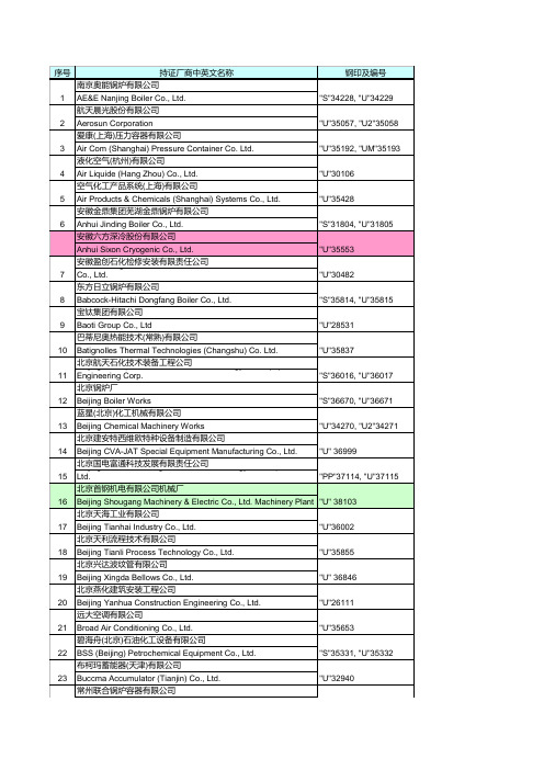
压力容器名录
24 25 26 27 28 29 30 31 32 33 34 35 36 37 38 39 40 41 42 43 44 45 46 47 48 49
Chang Zhou Union Boiler & Pressure Vessel Co., Ltd. 常熟市高压容器制造有限公司 Changshu High-Pressure Vessel Manufacturing Co., Ltd. 常熟市医药化工设备总厂 & Chemical Equipment General Changshu Pharmaceutical Factory 常熟市上海飞奥压力容器制造有限公司 Vessel Manufacture Changshu Shanghai Fiorentini Pressure Co., Ltd. 常州锅炉有限公司 Changzhou Boiler Co., Ltd 常州市华立液压润滑设备有限公司 Changzhou Huali Hydraulic Lubrication Equipment Co., Ltd. 常州蓝翼飞机装备制造有限公司 Changzhou Lanyi Aircraft Equipment Manufacture Limited Company 常州市第二化工机械制造有限公司 Changzhou No. 2 Chemical Machinery Manufacture Co., Ltd 常州综研加热炉有限公司 Changzhou Soken Boiler Co., Ltd. 常州斯派克能源设备有限公司 Changzhou Spark Energy Equipment Co., Ltd 查特深冷工程系统(常州)有限公司 Chart Cryogenic Engineering Systems (Changzhou) Co., Ltd. 成都波威特斯空调技术有限公司 Chengdu Provides Air Conditioning Technology Co., Ltd. 成都天人压力容器厂 Chengdu Tianren Pressure Vessel Factory 中国第二重型机械集团(德阳) China Erzhong Group (Deyang) Heavy Industries Co., Ltd. 中国第二重型机械集团(德阳) China Erzhong Group (Deyang) Heavy Industries Co., Ltd. 中国第一重型机械集团公司 China First Heavy Industries 中国第一重型机械集团公司 China First Heavy Industries 中国华电工程(集团)有限公司 China Huadian Engineering Corp. 中国石油六建公司钦州港金属结构厂 China Petroleum 6th Construction Company 中国石油天然气第七建设公司机械设备工程分公司 China Petroleum 7th Construction Company
哈法亚油田项目铸就海外油气田设计高端品牌
创新管理DOI:10.16660/ki.1674-098X.2103-5640-4971哈法亚油田项目铸就海外油气田设计高端品牌周靖伟(中国石油工程建设有限公司(CPECC)北京设计分公司工艺室 北京 100085)摘 要:伊拉克石油工程建设市场潜力巨大,互补性强,又极富挑战性和风险性。
中国石油与国际合作的哈法亚油田巨型整装油田项目依靠科技创新力压群雄,取得了很好的经济效益和社会效益,造福了当地人民。
本文简要介绍了伊拉克哈法亚油田工程项目概况、项目主要风险、设计规划、特色技术和实施效果。
充分继承和发扬这些经验与教训,可使在中东地区的中国总承包企业少走弯路,提高经济效益与社会效益。
本文的成果与经验对中国在中东地区的石油投资、项目管理、安保等具有重要参考意义。
关键词:环保 特色技术 合作共赢 国际品牌 哈法亚油田中图分类号:TE31 文献标识码:A文章编号:1674-098X(2021)05(a)-0196-05International High-End Brand on Oil-Gas Design of HalfayaOilfield ProjectZHOU Jingwei(Process Department of Beijing Branch, China Petroleum Engineering & Construction Co., Ltd., Beijing,100085 China)Abstract : The potential market of petroleum engineering construction in Iraq is enormous. The economies between China and Iraq are complementary to each other. The market is full of great challenge and risks. CNPC has wined all the oil giants by use of technical innovation and has obtained very good economical & social benef it in the giant integrated oilf ield, benef iting local people. The project prof ile, main risks, design layout, special technologies, effect of project execution in Halfaya oilf ield is brief ly introduced in this paper. These experience and lecture helps China companies engaged in EPC projects in the Middle East to improve their economic and social benef it straightly. The achievements and experience in this paper have very important reference sense to petroleum investment, project management and security etc. of China enterprises in the Middle East.Key Words : Environmental protection; Special Technologies; Win-win cooperation; International brand; Halfaya oilf ield作者简介:周靖伟(1994—),男,硕士,助理工程师,研究方向是油气田地面工程的工艺设计、油气设计管理。
tight oil
SPE 116105Unlocking Tight Oil: Selective Multi-Stage Fracturing in the Bakken Shale Brent Miller and John Paneitz, Whiting Petroleum Corporation, and Sean Yakely and Kent Evans, Baker Hughes Copyright 2008, Society of Petroleum EngineersThis paper was prepared for presentation at the 2008 SPE Annual Technical Conference and Exhibition held in Denver, Colorado, USA, 21–24 September 2008.This paper was selected for presentation by an SPE program committee following review of information contained in an abstract submitted by the author(s). Contents of the paper have not been reviewed by the Society of Petroleum Engineers and are subject to correction by the author(s). The material does not necessarily reflect any position of the Society of Petroleum Engineers, its officers, or members. Electronic reproduction, distribution, or storage of any part of this paper without the written consent of the Society of Petroleum Engineers is prohibited. Permission to reproduce in print is restricted to an abstract of not more than 300 words; illustrations may not be copied. The abstract must contain conspicuous acknowledgment of SPE copyright. AbstractIn recent years, the formation known as the Bakken Shale in eastern Montana and western North Dakota has seen enormous growth in oil and gas production. Scientists from the United States Geological Survey have commented that the area has the potential to become “the next Saudi Arabia.”In most cases, the Bakken horizontal wells are fracture stimulated. However, with several thousand feet of formation, effective stimulation of the entire length has proven time-consuming and costly. In the past, a single-leg zone was fractured all at the same time, regardless of the varied permeability of the layers. Although this simple method of stimulation was seen as a success at the time, a new, more efficient method using swellable packers with reactive elements now promises to optimize total recovery and minimize fracturing cost.Case history data will show how employing multiple frac sleeves with swellable packers straddling each interval proves to be a cost-effective way to stimulate multiple zones and save days of rig time. Specific experience in the Bakken field provides an optimization model for worldwide well completion marketsUnlocking Tight OilTraditional methods for tight oil drilling often include several costly steps to open up new veins: multiple downhole trips, cementing, plugging, perforating and finally fracturing. With the reactive-element packer method, the open-hole packers segregate multiple frac sleeves used to set up and designate multiple fractures on a horizontal wellbore. This segmenting process allows for more fractures, reduces the time and cost for hydraulic fracturing, accelerates production and improves reservoir drainage.In the Middle Bakken formation at the Sanish Field, North Dakota, an independent contractor sought a frac stimulation procedure to increase overall production while reducing well construction and completion costs. The contractor selected a successful recent innovation ─ reactive-element (swellable) packers ─ to perform an eight-stage compartmentalized frac job.ChallengesThe efficacy of frac stimulation is diminished when laterals exceed 5,000 ft. running an eight-stage frac job at more than5,000 ft. involved even greater challenges.Major pumping investments are often required for tight shale formations. Traditional methods include pumping frac fluid into the open hole or isolating separate zones of a horizontal wellbore. The former method typically results in the frac fluid flowing to areas of least resistance, which can reduce production along the rest of the wellbore. The latter method typically includes several steps (repeated cementing, plugging, perforating and fracturing) and will also require multiple trips as well as the expense of additional crew and equipment for the duration of the operation.ComponentsThe operator selected a Baker Oil Tools open-hole frac system comprised of four primary technological components -- a liner top packer, open-hole packers, ball actuated frac sleeves, and pressure-actuated sleeves (P sleeves). (See Figure 1). The liner top packer is run on top of the completion and is hydraulically set by landing a ball on seat in the toe of the completion and applying internal hydraulic pressure to set the hanger/packer portion of the tool. This packer creates isolation to the annulusof the liner to allow a casing frac to be performed, as well as anchors the liner in the casing so that it is not affected by frac and production pressures. The open-hole packers create a pressure tight seal in the open hole allowing compartmentalization of the zone. The frac sleeves are placed between the open-hole packers, which provide pressure and fluid communication so that each zone can be independently fractured. Finally, the P sleeve is installed below the bottom-most open hole packer. This sleeve does not contain a ball seat, but is shifted with internal pressure.The P sleeve and frac sleeves are opened sequentially, with balls dropped into ball seats sized accordingly, which isolates already treated lower intervals. The balls and seats can be sized up to nearly the full operating ID if necessary.Because the frac system used is a one-trip system, fracture treatments can be completed in sequence, and in most instances the entire multistage fracture can be completed in one day. In-depth upfront analysis allows the system to be deployed with a strategy based upon traditional project management concepts.Analysis, Selection and InstallationA well-defined project management methodology was necessary. The first phase – Feasibility – verifies the operator’s data and prepares preliminary options; this step allows for collaboration by all decision-makers throughout the process. The feasibility analysis ensured that not only would the designed equipment work but that the proposed completion was the most optimal for the application. Among the critical data considered were bottomhole temperature, expected treating pressures and expected flow rates during the stimulation phase. Additionally, it was of the utmost importance to do extensive fluids analysis on the completion fluid as well as the produced oil and water (if any). This analysis was required because the REPacker can be deployed in either water or oil-swelling elastomer, and for each one the fluid type is critical in the planning phase. In order to validate the use of REPackers in the fracturing application, a series of full-scale tests were carried out up to 10,000 psi (with no bypass) as seen in Figure 2.The Selection Phase analyzed possible choices and risks, such as number of zones, conductivity and dimensions of fractures. Once the packers were qualified and met the requirements per design, the completion was selected and mobilized to location. During the Execution Phase, the installation and stimulation took place, carefully monitored by both the operator and Baker Oil Tools. Finally, the operator evaluated the performance of the operation, measuring results and producing lessons learned.A side benefit to following this process is that the operator and the service company can analyze the voluminous pre- and post-completion data to determine the efficacy of the project. This methodology allows for fine-tuning of the process to further enhance the process for additional wells.Bakken Frac DesignThe swellable packer/frac sleeve design for the Bakken job required the operator to drill down two miles (3.2 km), then move lateral and drill sideways for an additional two miles to create a single horizontal completion. The design required completing the well in eight to ten stages, with swell packers separating the frac sleeves along the lateral. Each stage used progressively larger balls, with the smallest at the farthest end of the drilling, and the largest closer to the start of the drilling, as the ID increased. As each section was completed, a ball would be dropped to isolate that section.The operator had originally planned to run the job in brine water, with an estimated 28 to 36 hours to trip the tools to total depth, but due to bottomhole pressure, the brine had to be swapped over to oil-based mud (OBM). To mitigate any premature swelling, the OBM was immediately tested. The results from the test showed that the OBM would swell the packer to full open-hole ID in 48 hours (See Figure 3). To successfully deploy the system, an effective retardant had to be found.Baker Oil Tools coordinated an effort that extrapolated swell rate at various depths and temperatures, giving the operator a matrix to show swell rate over trip time. Through rapid and efficient collaboration, a new retardant was discovered and tested in less than one week. The application of this unique material allowed the open-hole packers and open-hole frac sleeves to be deployed successfully.The final completion of utilizing standard liner top equipment with the combination of frac sleeves and packers allowed the operator to minimize risks and costs associated with cementing and perforating. The fracture treatment was pumped approximately one month after the completion was run. All balls seated and all the sleeves shifted as expected.ResultsThe pre-job planning and mobilization in shop resulted in savings of six hours of trip/rig time. The analysis before and during the job resulted in more accurate placement of frac sleeves, resulting in more production than possible with other methods. The packers and frac sleeves achieved a new performance record for horizontal extended reach – 7,740 ft (2,359 m). Using conventional perforating guns and composite plugs during winter months could have taken more than four days. The ability to frac the entire interval in 12 hours resulted in significant operator savings. Also, the new retardant developed is now available for similar contingencies.The well was drilled with 7 ft, 29 lb/ft and 32 lb/ft casing set through the curve with a 12°/100 ft build rate at a depth of 9,920 ft TVD at 90°. The 4.d in, 11.6 lb/ft L-80 LT&C liner was run with 7 3-ft oil swell packers, 7 frac sleeves and one pressure activated sleeve. The total horizontal pay was 7,740 ft with 8 compartmentalized zones. Once TD was reached, diesel was pumped into the annulus and a ball was dropped behind the diesel. With the diesel displaced into the annulus and the setting ball on seat, the liner hanger was set, the running tool was released, and the liner top packer was set. With the activation fluid in the annulus the rig was rigged down as the operator scheduled the fracture. With a bottom hole temperature of about 210°F, it was expected that the swell packers would only need three days to reach full differential.Once the packers had ample time to swell, the fracture treatment took place. The first stage was pumped through the pressure-activated sleeve once it was opened with 4,000 psi of tubing pressure. The following 7 stages were all pumped through ball actuated frac sleeve. The entire 8-stage frac was completed in 10 hours, and over 1.9 million lbs of sand were pumped into the different stages. The average treating pressure was 4,500 psi with a maximum treating pressure of 7,186 psi seen, with an average pump rate of 39 BPM.The initial production for the well 1,323 barrels of oil and 2.0 MMcf of gas during a 24 hour flow test. Over the next 30 days, the well averaged 818 barrels of oil and 828 Mcf of gas production per day (See Figure 4)Employing multiple frac sleeves with swellable packers straddling each interval proved to be a cost-effective way to stimulate multiple zones and saved days of rig time, reduced cost, and resulted in greatly increased production. To date, at least ten more wells in the region have been completed with swell technology in multiple different configurations to optimize the production for each well. Specific experience with this technology in the Bakken formation exceeds all expectations and provides a model for the worldwide well completion market.Figure 1. LIFFRIG 11-27H Hook-up DrawingFigure 2. REPacker Fullscale Pressure TestFigure 3. Swell PREdictor PlotFigure 4. Post-job Production Data Plot。
斯派莎克蒸汽疏水阀 产品应用指南说明书
疏水阀产品应用指南Steam Traps o l u t i o n s● 我们的子公司、办事处及授权经销商遍布全世界100多个国家和地区●35个培训中心与您分享知识产品可持续发展(Sustainability)斯派莎克将致力于为客户管理好您的蒸汽系统,提供全面的能源审计,或是为您的质量、业务或生产方面的问题提供全套产品和服务,满足您的可持续发展目标。
专业技术(Expertise)斯派莎克的专业知识和技能源于100多年来的全球蒸汽工程应用经验。
这些知识和技能通过全球的35个培训中心,各种培训课程和技术出版物向客户传播。
我们所运用的专业技术是可以为客户提供的最基本而最宝贵的部分,也正是这些因素让我们与众不同,成为行业中的领先者。
斯派莎克是专业致力于推广有效的使用和控制蒸汽、热水和压缩空气等多种工业流体的节能公司。
斯派莎克在全球范围内使用专业知识和技能为广大蒸汽用户提供解决方案,从而显著提高其设备性能和系统效率,节约能源,满足您的可持续发展目标。
斯派莎克公司历史可追溯至1888年,1937年建址于英国,1959年斯派莎克集团公司在伦敦股票市场上市,每年均有骄人的业绩报告。
斯派莎克在英国、法国、德国、美国、阿根廷、巴西、意大利等国家均有生产基地,质量管理通过ISO9000体系认证,产品通过PED 认证。
解决方案(Solutions)斯派莎克作为蒸汽及热能整体解决方案提供商,我们将根据您工艺应用的具体需求,提供具有针对性的产品、系统与服务,对蒸汽和相关工艺产生的废弃物中热能的控制、再利用、回收和储存做出改造,从而达到降低您的成本,改进工艺可靠性及能效水平,帮您提高生产效率与利润。
●1000位销售工程师竭诚为您服务●100,000位长期客户遍布全球/cn斯派莎克蒸汽疏水阀斯派莎克的历史可以追溯到1888年,世界上第一台疏水阀就是由斯派莎克生产的。
经过100多年的发展,斯派莎克已经能够提供浮球型、热动力型、热静力型、双金属式和倒吊桶式等各种形式的高品质蒸汽疏水阀,至今已广泛应用在各种设备上,得到客户高度好评。
哈里伯顿推出油气行业首款智能自动化压裂系统

第27卷 第5期 2020年10月曲岩 等:预算支出授权批准书在预算管理中的应用——以大港油田赵东合作项目为例 践,建立起了事前批复、事中控制、事后分析的闭环预算管理体系。
通过强化方案设计、严格预算编制和授权审批,将投资支出和责任落实细分到各部门,充分发挥了各部门的主观能动性,杜绝了没有预算未经批准的项目执行。
(3)AFE管理模式与生产管理系统、会计核算系统进行有机结合,可及时、准确地反映出预算执行偏差,严格控制投资支出在预算范围内运行,有效地发挥预算控制的职能,并通过对实际发生数据的有效分析和总结,不断完善基础数据库,不断提升管理经验,为今后的预算编制和投资决策提供了决策支撑和价值引领作用。
参考文献:[1] 张永德.大港油田滩海油气勘探开发形势及工程建设总体思路[J].中国海洋平台,2000(1):10-15.ZHANG Y D. Situation of offshore oil and gas exploration and development in Dagang oilfield and general idea ofengineering construction [J]. Chswina offshore platform, 2000 (1): 10-15.[2] 王雪.基于全面预算的海外石油项目价值管理研究[J].中国集体经济,2015(33):49-50.WANG X. Research on value management of overseas oil projects based on comprehensive budget [J]. China collective economy, 2015 (33): 49-50.[3] 闫建华.中国石油上游国内对外合作赵东项目的启示[J].北京石油管理干部学院学报,2006(3):36-38.YAN J H. Enlightenment of domestic and foreign coopera-tion project in upstream of PetroChina Zhaodong project [J]. Journal of Beijing petroleum management training institute, 2006 (3): 36-38.[4] 刘立旺.基于全面预算的海外石油项目价值管理研究[D].天津:天津大学,2013.LIU L W. Study on value-based management based on overall budget management in overseas petroleum project[D].Tianjin: Tianjin university, 2013.[5] 李淑琴,徐洋.适应“走出去”项目“国际化”[J].中国石油企业,2012(1):124-125.LI S Q, XU Y. Project internationalization and adapt to go out [J]. China petroleum enterprise, 2012 (1): 124-125.(编辑:刘芳)哈里伯顿推出油气行业首款智能自动化压裂系统据世界石油网站(World Oil)2020年10月16日休斯敦报道,哈里伯顿公司推出油气行业首款智能自动化压裂系统——SmartFleet系统。
OTC-25767-MS
OTC-25767-MSConceptual Design for Offshore Pipeline Replacement in Mature Field, Using Reinforced Thermoplastic Pipe for CAPEX Optimization in F-Field Pipeline Repair and Replacement ProgramHanto Yananto,Pertamina Hulu Energi ONWJ;Yuyung Girindra,Pertamina Hulu Energi ONWJ;Steven Kennedy,Polyflow GlobalCopyright2015,Offshore Technology ConferenceThis paper was prepared for presentation at the Offshore Technology Conference held in Houston,Texas,USA,4–7May2015.This paper was selected for presentation by an OTC program committee following review of information contained in an abstract submitted by the author(s).Contents of the paper have not been reviewed by the Offshore Technology Conference and are subject to correction by the author(s).The material does not necessarily reflect any position of the Offshore Technology Conference,its officers,or members.Electronic reproduction,distribution,or storage of any part of this paper without the written consent of the Offshore Technology Conference is prohibited.Permission to reproduce in print is restricted to an abstract of not more than300words; illustrations may not be copied.The abstract must contain conspicuous acknowledgment of OTC copyright.AbstractA study was initiated to evaluate the benefit of low capital cost and low maintenance cost technologies to rehabilitate pipelines in marginal fields and apply artificial lift solutions to marginal wells to keep them running profitably and with an attractive return on investment(and with no sacrifice to safety and environmental risks).The challenge is to have a new technology with lower“Total”cost from design,procurement, installation,operation and maintenance during its life time.In addition,the technology must meet the required planned production flow,which,in some cases,can be higher than current flow.RTP per API15S was shown as the most cost effective solution in rehabilitation of pipelines in marginal fields.IntroductionOffshore North West Java(ONWJ)field has been operated for more than40year and comprises9 flow-stations and hundreds of NUI platforms.About600pipelines are used for transporting either fluid or gas.At least5pipelines have to be repaired or replaced due to integrity of aging facilities.As a mature field,any additional Capex to maintain base production shall be carefully assessed.Figures1and2show examples of“F”field network.The objective of this paper is to evaluate and select the right existing pipeline candidates that are suitable for pipe in pipe pull through method.Success criteria include acceptable hydraulics which meets line requirements,flow velocity minimum performance to minimize maintenance expenses,material selection to eliminate chemical treatment and capital cost estimates to demonstrate a beneficial return on investment to ONWJ.Pipeline Replacement StrategyThe replacement strategies followed by ONWJ are according to the following steps,i.e.–To utilize the existing pipeline casing as the conduit for RTP flow line pull through method.–RTP flow line will be pulled through from tie-in flange below Emergency Shutdown (ESD)Valveat one platform to the same elevation at another designated platform.–RTP diameters which meet the hydraulic method and do not require a modification to existing riserbends are preferable to those that require riser bends.–Modifications to bend does not constitute a rejection of the process.ROI analysis will determineif project is viable.–Total installation cost comparison will be generated to compare technology options.Design ScopeThe assessment effort was limited to a process that will engage the lower hanger flange (just below the Emergency Safety Valve)on one platform to the lower hanger flange of the terminating platform,as in Figure1Figure 1—Pipeline Network atF3-F2Figure 2—Pipeline Network at FS1-FS231-F261Appraise StageIn the appraise stage,several technology options were considered to select the best option to maintain the pipeline;API 17J Flexible Pipe and API 5S RTP with Pull-Thru Installation method are the alternative options compared to traditional rigid carbon steel pipeline..Commercially Available Pipe SizingThe new pipeline will be designed to anticipate maximum fluid or gas production from the existing platform.It is essential to establish the right size of the pipe for current and future operating requirements as proper pipe sizing can minimize the ongoing maintenance by creating critical velocities to move solids with the liquid flow stream.One of the benefits of RTP and Flexible pipe systems are their polymer liners which are smooth extruded surfaces compared with carbon steel pipe.These smooth liner surfaces reduce flowing pressure drop for comparable diameters,thus allowing smaller diameter RTP to replace larger diameter carbon steel pipe.References have shown carbon steel to have a relative roughness of ~0.006in/in versus thermoplastic extruded relative roughness of ~0.00005in/in.This allows for smaller diameter polymer lined pipes to create critical minimum velocities to move solids while not creating excessive pressure drop.Modeling was performed to establish the desired diameter using a polymer lined pipe.Table 1summarizes the comparison between new line size and commercially available existing pipeline size for API 5S,API 17J and steel pipe.Technical selection was later performed based on market availability,material capabilities,practicality in installation,pipeline size andlength.Figure 3—Design ScopeInstallation Total Cost ComparisonTable 2shows an installation total cost comparison for the various technologies assessed.The least cost total installation cost technology)is RTP per API 15S.Flexible pipe per API17J is more expensive and carbon steel per API 5L the most expensive.●RTP (API15S)~$2MM USD less than API 17J flexible ●RTP (API15S)~$3-4MM USD less than carbon steelInstallation ScheduleOne additional advantage that flexible pipes have over carbon steel pipes is in the duration of the installation.Figure 4shows a generic “pipe-in-pipe”installation schedule for RTP per API 15S for pipeline lengths less than 5km.Table 1—Technical Selection Pipeline candidates inF-FieldTable 2—Price Comparison of Selected Pipelines inF-FieldRTP per API15S was seen to offer the least cost total rehabilitation solution and was then selected best return on investment for use in marginal fields.Following is a more detailed discussion of RTP technology.Selection of New PipelineThe new pipeline is proposed to be installed by using Reinforce Thermoplastic Pipe (RTP).The general construction of RTP piping system consists of an internal liner and substructure (either Nylon or PPS)that is wrapped externally by aramid fibre in order to increase allowable pressure of polymer pipe.The PPS liner is recommended due to its low permeation rates for both CO 2and H 2S gasses.The Fortron liner has a relative roughness friction coefficient of 0.00005in/in was used which approximately a hundred times less than the value is used for steel pipe (0.006in/in).RTP line will be installed inside of existing carbon steel pipeline using method called Pull Thru.The existing line is currently no flow since the platform is inactive now.The main concern of using this method is the capability of existing bends in the steel in handling RTP inside which depend on the size of the RTP used.Bend modification,if required,will give impact to the ROI calculation.Material comparison of RTP and steel pipeline is shown in Table 3.Hydraulic simulation of the new pipeline comparing RTP and carbon steel line is summarized in Table 4.Figure 4—Generic Installation ScheduleTable 3—MaterialComparisonAs shown in Table 4,for 6inch pipeline,generally RTP and steel pipeline generate similar pressure drop (only 0.2psi difference).For 4inch,pressure drop along the steel line is higher than pressure drop along RTP,as well as for 3.5inch.It shows that for small diameter,the RTP will generate less pressure drop.Still shown in Table 4,fluid velocity for RTP is quite higher than steel line.It minimizes solid deposition as long as it is still lower than erosional velocity.An operational cost avoidance benefit of the higher velocity is the possible elimination of pigging operations.Another significant cost benefit for RTP is in the installation process and associated cost.Steel line lay process requires lay barge,possibly DP2vessels,which resulted in high cost installation.RTP system can use small work barges and utility vessels to transport small machinery and materials hence the installation cost will be less expensive.Table 5shows options selection by comparing advantage and disadvantage of various sizes and material of pipeline.Generally steel has proven reliability but the installation cost is very high.On the other side,RTP installation and operational costs are lower but reliability is unknown since it has never been implemented on this field.For similar size,RTP generate less pressure drop than steel line.Due to that reason,RTP will be more efficient to be implemented first time in the recommended options since it is only for gas lift.Six (6)inch size will be oversized considered the maximum rate is only 3.4MMSCFD.The allowable pressure drop along the line should be about 10-20psi/mile (6.2-12.4psi/km).The 3.5”RTP and steel is resulted in very high pressure drop (48and 50.1psi).The only option left is 4”which Table4—Comparison of hydraulic simulation result using RTP and Carbon SteelNominal Size PipelineRequirement for bend modification Resulting Pressure Drop (psi)Landed Pressure (psi)Velocity (ft/s)6”RTP3.6671.48Yes 6”Steel3.4671.6 5.5-4”RTP2465118No 4”Steel2664912.8-3.5”RTP4862724No 3.5”Steel 50.1624.916.3-Table 5—Option Selectionis technically and commercially feasible since it is resulted lower pressure drop (24psi)and the cost is cheaper than installing new steel line.Bend Modification ImplicationsAn additional consideration in pipeline rehabilitation or conversion of lines to gas lift etc.is whether the existing bends in the steel casing need to be modified.This is a critical cost impact item in the Return on Investment (ROI)calculation –not as important when production flow is sizeable but very critical for pipe-in-pipe applications in marginal fields.The recommended initial applications do not require modification to existing bends.RTP Pipeline DataThe line pipe is described as Piping and associated Joining System pulled inside the existing steel line pipe casing.In combination,both systems provide a stable flow line system for the transport of gas/crude or other products.The existing carbon steel casing does not require the use of anodes,cathodes or other corrosion inhibitors as a requirement for further operation as the RTP pipe will assume all the integrity requirements for flow.This can result in a significant operation cost avoidance.By nature,the piping system is inert to hydrocarbons;except for flange and splice sections which can be coated (inner tubular)with surface protectant;such as Fortron Polylphenylene Sulphide (PPS)or other coating,prior to installation.Material SelectionThe RTP pipe evaluated was constructed with internal liner of Fortron Polyphenylene Sulfide (PPS),reinforced with aramid fibers and jacketed with Nylon (refer to Figure 5)The PPS liner was selected because of its resistance to hydrocarbons and Brine,as well as CO 2and H 2S.In addition,PPS exhibits very low permeation rates for both H 2S and CO 2gas.PermeationPermeation through the liner does not necessarily damage the liner but rather can create operational issues such as build up gas pressure in the reinforcement layer creating issues with the outer jacket.In the case of the rehabilitation of a carbon steel pipeline,a build up of gas in the annulus between the RTP and the steel pipe can create non desirable issues.The Figure 6is comparing various polymers permeation rates in CO2at various temperature to show a side by sidecomparisons.Figure 5—RTP Pipe ConstructionFigure 6shows that polyethylene,a common polymer used in the oilfield has significant permeation rate compared to the other engineering plastics and Fortron (PPS)showed significantly lower levels of permeation.No Venting RequiredSafety is of critical concern for ONWJ.Therfore,it is preferable to have a pipe-in-pipe system that does not require venting of the annulus as a consequence of gas permeation through the RTP wall into the annulus.This criteria negated the use of polyethylene (PE)based liners and materials.PPS liners do not require venting of the annulus.Typical RTP Installation MethodThe first step in installation is to disconnect the terminations at the lower hanger flange as in Figure 7(before the safety shut off valve).In some cases due to limited space the safety valve and associated piping might be removed to gain acceptable access for pull through.Operational Pigging PhilosophyOnce the lower hanger flanges are disconnected,a gauging pig will be sent through the line with cable attached to assure that the existing casing has an acceptable size opening to accept the RTP.For sending of the gauging/messenger pig,a compressor isrequired.Figure 6—Comparison of Polymer PermeationRatesFigure 7—Typical Lower Hanger Flange Access /Disconnected FlangeThe compressor will be integrated with a temporary pigging joint “in-line”.Figure 8gives a visual of this connector type which is standard in industry.When messenger process is complete this joint is removed.The temporary pig launcher will have flange connection to connect with existing terminations at the platform.Pulling MethodA pulling cone is attached to the RTP pipe.The pulling cone has holes that allow for water to fill the pipe as it is pulled within the steel casing.The operator must use a light weight,high strength rope for the messenger pig and pull through operation.A winch and rope should be capable of pulling with greater than 2x the expected pulling force (which will provide the operator with a suitable safety factor).The pull through speed is expected to be 7-14m/minute.Speed is monitored via winch controller.A faster pulling rate is possible when the size of the casing is much larger than the RTP pipe.As one RTP spool is completely unwound,the pull is stopped,the existing empty spool removed and replaced with a new spool in the unwinding station.Then a splice coupling is used to join the two pipe sections and continue spooling.A custom designed 10,000psi rated pump is required to swage the couplings at joining locations.The final issue is determining the end connections.When possible it is recommended to flange to the existing steel flange termination because as the RTP pipe is flexible,terminating to a non-rigid structure can cause some issues with excessive bending.The pipe is then pulled past the lower flange hanger (~5-10m)and the pipe is cut near the lower flange.The proprietary termination coupling is then added using the hydraulic press.Terminations are provided that mate to the existing flange structure.The termination flange is then bolted to the lower hanger flange assembly to close off the pipe in pipe system.Pre-commissioningThe final installation process step is to hydro-test the line to ensure splice and termination joint integrity.In general,the installation contractor will follow the following recommended hydro testing guidelines for RTP.Typically the hydro-test is done at 1.5x the “operating”pressure for gas lines and 1.25xthe Figure 8—Messenger Pigoperating pressure for liquid lines of the line for an 8hour period.However,there are a few requirements from the RTP Supplier:1.Pressures testing should be done with liquid (salt water is acceptable).2.The line should be increased in 250-500psi increments and held for ~15-20minutes before increasing pressure,thus allowing the pressure to stabilize.(There is some stretching of the line and pressure drops can occur during the pressurization of the line.)3.Once the final pressure is achieved,there may be a few recharges required during the pipe relaxation before the pressure test hold procedures begin.4.The pressure profile curve is asymptotic,so there may be slight pressure decay for several hours before the pressure stabilizes.ConclusionsDuring Appraise-Select Stage,3pipelines were proposed to be replaced with RTP by pull through method as shown in Table 6.The budget required for capital expenditure on those RTP pipelines can be optimized to 56%of regular carbon steel pipeline laying by pipe lay barge as shown on table 7.Additional operation cost reductions can be acheived from RTP systems by elimination of pigging operations and chemical injections associated with carbon steel pipelines.The following is the summary of selection RTP as the most valuable for those 3pipelines.–Pulling Through method is the most valuable solution for pipeline rehabilitation in marginal fieldwhere there were suficient existing abandoned pipeline as casing for RTP pipe.–No subsea intervention,but might need subsea team support to be standby during pigging.Table 6—Summary of RTP pipelinecandidatesTable 7—Summary of CAPEXoptimizationOTC-25767-MS11–For the selected lines,the maximum size RTP applicable for existing pipeline as casing without modification is about4”,All for gas lift.Pipeline rehabilitation using RTP technology has the potential to greatly impact the performance of marginal fields.Rehabilitation of existing lines can realized~56ϩ%less capital cost compared to an installation using conventional carbon steel pipeline.Proper planning and analysis of the pipeline to be rehabilitated shall be executed at earlier stage to ensure smoother installation process and better achievement to the project in term of schedule and expenditure spending.REFERENCES-N/A。
戴维斯贝斯核电站上封头降质
诱因:控制棒驱动 机构导向管接管管 口已经产生裂缝
戴维斯 贝斯核电站(Davis Besse)第十二次大修
戴维斯 贝斯核电站压力容器顶盖严重腐蚀
压力容器顶 盖降级区域
戴维斯 贝斯核电站压力容器顶盖严重腐蚀
空穴
封头 CRDM 接管 #3 (拆除)
CRDM 接管 #1
不锈钢堆焊层 CRDM 接管 #11
戴维斯 贝斯核电站压力容器顶盖严重腐蚀
•“A review of this incident shows the significant
Davis-Besse
பைடு நூலகம்
反应堆制造商:Babcock and Wilcox
电站设计人:通用电气 事件日期:2002年3月7日
2018/12/25 4
戴维斯 贝斯核电站压力容器顶盖严重腐蚀
事故概述
l 1990年控制棒驱动机构管嘴已经产生裂缝,
l 1994年顶盖碳钢母材金属开始腐蚀,
l 每年大修目视检查顶盖都发现硼结晶,
l 2001年NRC同意电厂申请延缓规定对顶盖的检 查, l 2002年停堆检查发现大洞。 一回路压力边界带病运行 12年!
忽略的迹象和机会
控制棒驱动机构管嘴 发生裂纹(1990年) RPV封头辅助结构修改 未被实施(1990年) 电站管理组没有提供 RPV封头检查的全面综述
稳压器喷水阀RC-2 上的3个碳钢阀帽体螺母 腐蚀严重 (1998年)
戴维斯 贝斯核电站压力容器顶盖严重腐蚀
事故影响
Ø INES分级:3级
Ø 反应堆关闭:2年
11
戴维斯 贝斯核电站压力容器顶盖严重腐蚀
多重屏障失效示意图
屏障缺陷越多,事件发生概率越高!
阿布扎比国家石油公司BIFP项目精细化管理下的吊装施工
现吊装施工程序,需要说明吊装程序中的每一个细节。
阿联酋官方语言为阿拉伯语,当地项目执行语言多为英语。
BIFP 项目的吊装方案需用英语编制,在内部审核后上传文件管理平台Wrench 进行审批。
Wrench 系统是一款基于互联网的文件管理平台,具备资料存储、在线审批、文件共享等功能。
在吊装方案审批环节,文控上传后由总承包商专业工程师审批,通过后逐级上报业主管理团队,Wrench 系统能够通过分析上传方案的专业、区域等信息来判断适用的审批流程,与方案审批流程相关的权限方均能通过系统查看吊装方案目前的审批进度和状态。
虽然Wrench 平台缩短了方案在每个审批环节的时间,但由于业主专业工程师和安全工程师会不断地提出意见要求完善施工程序,所以吊装方案审批流程时间通常较长,一般情况方案最终通过审批前会修改多次。
业主的专业工程师多针对方案的合理性和可操作性提出意见,比较容易修改。
安全工程师提出的意见大多针对具体安全措施,这些措施需要有数据或计算结果的支持,而不是“经验判断”,这使得方案修改的难度大大增加。
审批通过的吊装方案由业主在封皮上加盖Code A 的红色矩形印章,证明此方案可以出现在现场指导吊装作业。
1.2 工作前期危险性分析(task risk assessment)吊装前的危险性分析与吊装方案通常是一一对应的,按照阿联酋阿布扎比陆上石油公司的管理程序,工作前期危险性分析首先要由施工方技术人员、现场施工具体组织者(JP)、安全人员共同讨论,形成初稿。
然后由业主管理团队组织专题讨论会,专题讨论会由施工方技术人员、JP 、施工方安全员、施工方班组代表、PMC 施工负责人(JO)、PMC 安全员等相关人员参加,如果涉及到其他危险源,如H 2S 浓度较高地区作业(红区)或在跨越运行中的设施吊装等,还需邀请相应区域的运行管理部门的代表(IA 和AA)参加。
在专题讨论会上,参与人员在TRA 初稿的基础进行讨论,分析吊装施工各流程步骤存在哪些风险、风险等级、风险发生概率、风险量、相应安全措施等,最终结合各方意见定稿,并由各方签字。
TDS石油钻机顶驱系统
Varco Top Drives
Year DC 1982 1 1983 13 1984 14 1985 30 1986 18 1987 29 1988 44 1989 36 1990 59 1991 51 1992 26 1993 30 1994 45 1995 46 1996 32 1997 39 1998 43 1999 8 2000 12 2001 14
GE-752 DC
Motor Torque (Ft. Lbs.)
10,000 9,000
(Intermittent Duty)
8,000
7,000
6,000 5,000 4,000 3,000
GE-752 GE-752 DC Series
2,000 1,000
Link Tilt Assy.
Tool Joint Locks - 3
Torque Back-Up Clamp Assy. (Torque Wrench)
PH-100
Drill Pipe Elevator Pipehandler
© Varco International, Inc. - TDS-8SA - Version 2, October 1999. A.N.
1900 1910 1920 1930 1940 1950 1960 1970 1980 1990 2000 2010
Varco Top Drives
Drill Pipe Torque
100000 90000 80000 70000 60000 50000 40000 30000 20000 10000 0 0
© Varco International, Inc. - TDS-8SA - Version 2, October 1999. A.N.
PDLAMMPS近场动力学
Available to the public from U.S. Department of Commerce National Technical Information Service 5285 Port Royal Rd Springfield, VA 22161 Telephone: Facsimile: E-Mail: Online ordering: (800) 553-6847 (703) 605-6900 orders@ /help/ordermethods.asp?loc=7-4-0#online
Issued by Sandia National Laboratories, operated for the United States Department of Energy by Sandia Corporation. NOTICE: This report was prepared as an account of work sponsored by an agency of the United States Government. Neither the United States Government, nor any agency thereof, nor any of their employees, nor any of their contractors, subcontractors, or their employees, make any warranty, express or implied, or assume any legal liability or responsibility for the accuracy, completeness, or usefulness of any information, apparatus, product, or process disclosed, or represent that its use would not infringe privately owned rights. Reference herein to any specific commercial product, process, or service by trade name, trademark, manufacturer, or otherwise, does not necessarily constitute or imply its endorsement, recommendation, or favoring by the United States Government, any agency thereof, or any of their contractors or subcontractors. The views and opinions expressed herein do not necessarily state or reflect those of the United States Government, any agency thereof, or any of their contractors. Printed in the United States of America. This report has been reproduced directly from the best available copy. Available to DOE and DOE contractors from U.S. Department of Energy Office of Scientific and Technical Information P.O. Box 62 Oak Ridge, TN 37831 Telephone: Facsimile: E-Mail: Online ordering: (865) 576-8401 (865) 576-5728 reports@ /bridge
- 1、下载文档前请自行甄别文档内容的完整性,平台不提供额外的编辑、内容补充、找答案等附加服务。
- 2、"仅部分预览"的文档,不可在线预览部分如存在完整性等问题,可反馈申请退款(可完整预览的文档不适用该条件!)。
- 3、如文档侵犯您的权益,请联系客服反馈,我们会尽快为您处理(人工客服工作时间:9:00-18:30)。
Statoil Tordis SSBI project Norway, Tampen Block 34/7 Landmark: The world’s first full-scale commercial subsea separation, boosting and injection system. FMC has delivered a full-scale separation facility to enable re-injection of bulk water into a non-hydrocarbon reservoir (Utsira) and route hydrocarbons through a multiphase pump back to Gullfaks C. The Subsea processing System including boosting pumps has been designed to handle high amounts of sand (50-500 kg per day) with its sand management system. Along with other upgrades to the field infrastructure, the recovery factor for the Tordis field is expected to increase from 49 percent to 55 percent (approximately 35 million barrels).
The PLIM was installed during the field shutdown summer 2006. The water injection tree was installed early 2007, and the subsea separation, boosting and injection system summer 2007. Tordis Subsea Separation, Boosting and injection station is now onstream.
System Description: Pipeline Inline Manifold (PLIM) The PLIM was installed summer 2006 to interconnect the flowlines from the existing Tordis Subsea Manifold to the Gullfaks C platform, allowing rerouting of the Tordis well stream to Gullfaks C via the PLIM.
The PLIM allows full bypass of the Tordis Subsea Separation station, and was installed during a planned maintenance shutdown of the Gullfaks C Platform.
Water Injection Tree The Water Injection Tree is a simple Xmas Tree consisting of a 12” ball valve. A conventional internal tree cap is installed in the vertical entry section of the tree, allowing for workover of the well. The reinjected water is pumped through this Xmas Tree through a 13-5/8 casing direct into the Utsira water reservoir. This is a nonhydrocarbon reservoir with ambient pressure.
Subsea Separation, Boosting and Injection (SSBI) Station The Subsea Separation, Boosting and Injection Station separates the water from the wellstream which is reinjected through the large-bore Water Injection Tree. After separation, gas and oil are mixed and pumped via a multiphase pump back to the Gullfaks C platform. The SSBI Station was installed in October 2007.
The Separation Station contains the following main elements: Foundation Structure and Manifold The Tordis SSBI Station has a conventional, overtrawlable foundation structure supporting the manifold, the separator module and all other modules and components. The structure has four suction anchors, one in each corner for foundation and leveling.
The manifold module provides connection to the flowlines via the Rovcon connection system and interconnects the various modules.
Separator Module The well fluid from the Tordis field is first routed into the separator vessel. The inlet cyclone in the vessel does a first separation where the majority of the gas is separated out and routed through a separate gas bypass line outside of the vessel, thereby minimizing the size of the separation vessel. The remaining water, oil and gas are separated through the gravity principle inside the vessel. The water is the heaviest part, which is pumped via a water injection pump directly back into the Utsira reservoir through the Xmas Tree. Oil and gas are remixed and pumped through a multiphase pump back to the Gullfaks C platform. Any deposit of sand inside the separation tank is handled by the sand removal system.
The Separator Module is retrievable. Sand Removal System Any sand from the wellstream will deposit at the bottom of the separation vessel. A flushing system with specially designed nozzles has been developed to flush out the sand at certain intervals. The sand is transported into the Desander Module, and then mixed with the injection water and reinjected into the reservoir downstream of the water injection pump.
Water Injection Pump The Water Injection Pump is a Framo liquid pump which is driven by an electrical motor powered through an electrical power cable from the Gullfaks C platform. The pump can be retrieved for maintenance by a pump-running tool. Multiphase Pump The Multiphase Pump is a Framo multiphase pump, and is powered through an electrical power cable from the Gullfaks C platform. It can also be retrieved by the pump-running tool.
Other The Subsea Separation Station is equipped with two multiphase flowmeters (Roxar) which will measure the composition of the well flow to prepare the separation system settings. A level monitoring system is installed in the separation tank to monitor water, oil and gas interfaces which again provide input to the water pump speed. The Subsea Separation Boosting Injection Station includes one subsea control module to control the various functions of the station and communicate back to the Gullfaks C platform.