Growth of wide band gap wurtzite ZnMgO layers on (0001) Al2O3
掺杂维度和浓度调控的δ掺杂的La:SrTiO_(3)超晶格结构金属-绝缘体转变
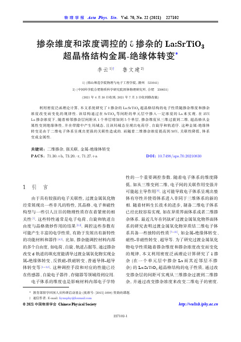
掺杂维度和浓度调控的d掺杂的La:SrTiO3超晶格结构金属-绝缘体转变*李云1)† 鲁文建2)1) (韩山师范学院物理与电子工程学院, 潮州 521041)2) (中国科学院合肥物质科学研究院固体物理研究所, 合肥 230031)(2021 年4 月30日收到; 2021 年7 月3日收到修改稿)利用密度泛函理论计算, 本文系统研究了d掺杂的La:SrTiO3超晶格结构的电子性质随掺杂维度和掺杂浓度改变而变化的规律性. 该结构通过在SrTiO3等间距的单元层中掺入一定浓度的La来实现. 在25% La掺杂浓度下, 随着相邻掺杂层间距从1个单层增加到5个单层, 掺杂维度从三维过渡到二维, 超晶格从金属性变到绝缘体性, 并在带隙中产生局域态, 且该局域态呈现出电荷序、自旋序和轨道序. 这种金属-绝缘体转变是由于二维电子体系呈现出更强的关联性造成的. 而随着二维掺杂浓度提高到50%, 关联性降低, 体系变成金属性.关键词:二维掺杂, 强关联, 金属-绝缘体转变PACS:71.30.+h, 73.20.–r, 71.27.+a DOI: 10.7498/aps.70.202108301 引 言由于具有较强的电子关联性, 过渡金属氧化物经常展现出一些非凡的特性, 其晶格、电子和磁性构型与一些引人注目的物理性质存在着紧密的相关性[1]. 这些特性通常是电子电荷、自旋和轨道自由度与晶格微妙作用的结果[2,3]. 调控这些参数有可能产生丰富的电学性质, 有助于发展出有新特性的功能材料和器件[4,5]. 比如, 掺杂能调控材料内部的多个自由度, 如电荷、自旋、轨道占据等, 通过掺杂改变d轨道的填充度能诱导过渡金属氧化物实现金属-绝缘体转变、反铁磁-铁磁转变、普通导体-超导体转变等[1−3,5]. 这种调控手段和对应的性能已经在传感器、自旋电子器件、存储器等领域得到应用.电子体系的维度也是影响材料内部电子学特性的一个重要调控参数. 随着电子体系的维度降低, 如从三维变到二维, 电子间的关联作用变强并可能起主导作用[6]. 这可能导致电子体系呈现出整体有序性并使得体系进入非同于三维体系的新的相. 随着材料生长技术的进步, 制备二维电子体系已经比较容易实现, 如在异质界面体系或者二维掺杂体系. 最近几年在钙钛矿过渡金属氧化物界面体系的研究表明过渡金属氧化物异质结二维电子体系具备一些独特的性质[7−21], 如金属-绝缘体转变、磁性-非磁性转变、超导等. 为了研究过渡金属氧化物电学性质随着掺杂维度和掺杂浓度改变而变化的规律, 本文利用密度泛函理论计算研究了d掺杂(在一个单元层中掺杂La而其近邻层不掺杂)的La:SrTiO3超晶格结构的电子性质, 通过改变掺杂层的间距可实现从三维掺杂过渡到二维掺杂, 并通过改变掺杂浓度来改变二维电子的密度.* 教育部留学回国人员科研启动基金(批准号: [2015]-1098)资助的课题.† 通信作者. E-mail: liyunphy@© 2021 中国物理学会 Chinese Physical Society 计算结果表明, 调节这些参数可改变电子关联强度进而实现体系的金属-绝缘体转变.2 计算方法计算由VASP 程序包执行[22], 其中采用PBE 型广义梯度近似泛函(PBE-GGA)[23]和投影缀加平面波方法[24,25], 平面波截断动能为500 eV. Ti 3d 轨道局域性较强, 轨道中电子的在位库伦相互作用较强, 计算中采用Dudarev 的LSDA+U 方法近似描述[26]. 计算中Ti 3d 轨道电子的在位库伦相互作用能分别取U =0, 2.0, 3.0, 3.5, 3.7, 4.4, 5.0 eV 等数值, 将不同数值得到的基态电子态与实验测得的电子性质对比进而确定出合适的U 值. 图1展示了两种超晶格原胞结构, 即[Sr 0.75La 0.25TiO 3]1|[SrTiO 3]n (n = 1, 5)(简写为[SLTO]1|[STO]n ), 其中掺杂层中25%的Sr 原子被La 原子替代, 沿着[001]方向周期性重复, 面内周期为4 × 4. 相应地,采用4 × 4 × 4和4 × 4 × 2的Monkhost 型k 点网格在布里渊区中取样. 有限温度展宽采用Gaussian 方法, 其中s = 0.1 eV. 计算中所有原子都充分弛豫, 直到受力小于0.01 eV/Å.(a)(b)(c)图 1 (a) 超晶格结构面内4 × 4周期俯视图; (b) [SLTO]1|[STO]1侧视图; (c) [SLTO]1|[STO]5侧视图. 绿色球代表Sr 原子, 蓝色代表La 原子, 红色代表O 原子, Ti 原子在八面体中心Fig. 1. (a) Top view of the superlattices with in-plane 4 × 4unit cells; (b) side view of [SLTO]1|[STO]1; (c) side view of [SLTO]1|[STO]5. Green balls represent Sr atom, blue balls La atom, red balls O atom, Ti atoms are at the centre ofthe octahedrons.3 结果和讨论SrTiO 3导带底部态主要由Ti 3dt 2g (d xy , d yz ,d xz ) 轨道构成, 掺杂La 的价电子轨道5d6s 能级高于SrTiO 3中的Ti 3dt 2g 轨道能级, La 掺杂产生的电子全部进入Ti 3dt 2g 轨道能级. 计算中Ti 3d 轨道在位库伦相互作用能U 为可调参数, 本文通过比较计算结果与实验结果来确定U 的最佳数值.图2展示了两种典型的U 计算的结果. 如图2(a)和图2(b)所示, 在U = 2 eV 情况下, 费米能级穿过导带下部, 两种结构都为金属态. 在U = 3.7 eV 情况下, 如图2(c)和图2(d)所示, [SLTO]1|[STO]1仍然为金属态, 而[SLTO]1|[STO]5为绝缘态, 费米能级穿过带隙, 且在带隙里出现局域态. 计算表明当U < 3.5 eV 时两种体系都是金属态, 而当U ≥ 3.5 eV 时[SLTO]1|[STO]5才会展现为绝缘态基态. 实验中观察到[SLTO]1|[STO]1呈现金属性,而[SLTO]1|[STO]5的电阻温度曲线为绝缘态且光电导检测表明带隙内存在局域态. 又考虑了50%La 掺杂结果和带隙宽度等因素后, 确定在上述超晶格体系中U = 3.7 eV 的计算结果与实验结果吻合最好.为了澄清[SLTO]1|[STO]5带隙内局域态的性质, 图3(a)和图3(b)详细地展示了其能带结构和局域态对应的空间电荷分布. 带隙内的局域态出现在掺杂的SrO 层两侧的TiO 2层内, 掺杂电子局域在Ti 原子的3dt 2g 轨道内, 则这部分有局域电子占据的Ti 原子呈现+3价, 其他Ti 原子呈现+4价. 计算表明Ti 3+—O 键长大于Ti 4+—O 键长, 由于外延生长限制xy 面内的晶格常数, 这导致掺杂层的TiO 6八面体受到了xy 面内的压缩应力, 使得原来简并的d xy , d yz , d xz 三个轨道劈裂, 最终d xy 轨道略高于d xz 和d yz 轨道, 因而电子优先占据d xz 和d yz 轨道. 如图3(b)所示, 在掺杂SrO 层一侧掺杂电子分布在Ti d xz 轨道, 而在另一侧则分布在d yz 轨道. 通过对多种自旋构型的计算比较, 结果表明图3(b)所示的反铁磁自旋序具备更低的能量. 图3(c)展示了局域态所在的Ti 3+与近邻的6个O 原子的键长, 沿着y , z 方向键长明显大于x 方向, 这与电子占据Ti d xz 和d yz 轨道相吻合. 计算结果还表明Ti 3+与近邻的O 原子的键长也明显大于Ti 4+与近邻的O 原子的键长.从体掺杂的角度看, [SLTO]1|[STO]5结构中La 离子平均体密度为4.17%, 而[SLTO]1|[STO]1结构中La 离子平均体密度为12.5%, 似乎La 离子的体密度与上述金属绝缘体转变有关. 而Tokura等[27]和Okuda 等[28]的实验结果表明在STO 内La 离子体掺杂密度在1.5%—92%区间内体系都呈现金属态. 由此可知, 在STO 中均匀掺杂4.17%的La 会导致金属态. 而d 掺杂的[SLTO]1|[STO]5超晶格结构中La 离子平均体密度同为4.17%, 却呈现绝缘体性, 这意味着掺杂维度变化是导致上述金属绝缘体转变的决定因素. 图4展示了三维掺杂和二维掺杂情况下杂质离子层在空间中产生的电势分布示意图. 在[SLTO]1|[STO]1掺杂情况下,如图4(a), 相邻的杂质离子层较近, 其吸引势相互D O S(a1)-4-20Energy/eV24 /e V(a2)3210-1/e V(c2)3210-1D O S(c1)-4-20Energy/eV24 /e V(d2)3210-1/e V(b2)3210-1D O S(b1)-4-20Energy/eV24D O S(d1)-4-20Energy/eV24图 2 分自旋总态密度图和能带图 (a1), (a2) U = 2 eV, [SLTO]1|[STO]1; (b1), (b2) U = 2 eV, [SLTO]1|[STO]5; (c1), (c2) U =3.7 eV, [SLTO]1|[STO]1; (d1), (d2) U = 3.7 eV, [SLTO]1|[STO]5, 红色箭头所指为带隙内局域态. 图中红线为费米能级, 价带顶部设为能量零点. 态密度图中水平线上部为上自旋态密度, 下部为下自旋态密度Fig. 2. Spin-polarized total densities of states and band structures: (a1), (a2) U = 2 eV, [SLTO]1|[STO]1; (b1), (b2) U = 2 eV,[SLTO]1|[STO]5; (c1), (c2) U = 3.7 eV, [SLTO]1|[STO]1; (d1), (d2) U = 3.7 eV, [SLTO]1|[STO]5, the in-gap localized states are pointed out by the red arrow. The red lines are Fermi level, the top of valence band is set to be zero.dddd(b)(c)Ti 3+Ti 3+2.012.082.022.07Ti 4+Ti 3+2.062.07Ti 4+-11/e Vdfd 23图 3 (a) [SLTO]1|[STO]5能带结构图, 其中带隙内局域态为Ti d xz 和d yz 轨道态. 水平红色虚线为费米能级; (b) [SLTO]1|[STO]5带隙内局域态电荷空间分布, 局域态为Ti d xz 和d yz 轨道态, 上下箭头代表自旋方向; (c)掺杂层局部结构和Ti 3+O 6八面体键长, 沿着y 和z 方向Ti 3+—O 键较长Fig. 3. (a) Band structure of [SLTO]1|[STO]5, in which the in-gap states mainly consist of Ti d xz and d yz orbitals; (b) charge distri-bution of the in-gap states, the charge is mainly localized at Ti d xz and d yz orbitals. The arrows represent spin directions; (c) local structure of the doped layer and bond lengths of Ti 3+—O bonds of the Ti 3+O 6 octehedron.重叠较大, 最终在空间产生较为平缓的势. 而在[SLTO]1|[STO]5掺杂情况下, 如图4(b)所示, 相邻的杂质离子层较远, 其吸引势重叠小, 最终在掺杂层形成势阱, 该势阱束缚了电子在垂直掺杂面方向的运动, 结果电子只能在掺杂层内运动. 通常,电子系统的能量取决于电子在邻近格点间跳跃的动能和电子间排斥势能的总和, 关联性强弱大致取决于电子间排斥势能与电子动能的比值, 比值越大则关联性越强. 相比三维掺杂, 二维掺杂情况下电子在杂质离子层的势阱中运动, 在垂直方向运动受限制, 允许电子跳跃的近邻格点变少, 总动能变小,电子运动关联性变强. 二维体系情况下, 若体系呈现金属态, 即电子可在近邻格点巡游, 则动能较低,但存在两个电子同时占据同一个Ti 原子3d 轨道的几率, 由于Ti 3d 轨道上存在较大的在位库伦排斥能, 这会导致较大的电子间排斥势能, 体系的总能量可能因此更高. 若体系呈现绝缘态, 带隙内局域态电子不能在近邻格点巡游, 则动能较大, 但避免了两个电子同时占据同一个Ti 原子3d 轨道引起的较大的在位库伦排斥能, 这降低了电子间排斥势能, 体系的总能量可能因此更低. 这意味着在同样的在位库伦排斥能情况下, 相比三维电子体系,二维电子体系具有更小的动能, 即更强的关联性,更容易变为绝缘态. 上述计算中得到的SrTiO 3中层状25% La 掺杂导致的金属-绝缘体转变正是电子维度降低导致关联性增强的一个实例.此外, 二维电子的密度也影响着体系关联性.从平均场的角度看, 二维电子体系的电子间排斥势能正比于n 1/2(n 为二维电子密度), 动能正比与n ,则电子间排斥势能与动能比值约为n –1/2[29]. 这意味随着二维掺杂浓度的提高, 关联性会变弱, 体系有可能从绝缘态变为金属态. 实验研究[16]和本文的计算都验证了这一点, 图5所示的态密度和能带结构表明当二维La 掺杂的掺杂浓度为50%时上述超晶格结构呈现金属态.D O S(a)-4-20Energy/eV24 /e V(b)3210-1图 5 50% La 掺杂的[SLTO]1|[STO]5总态密度图(a)和能带结构图(b), 红线为费米能级Fig. 5. Total density of states (a) and band structure (b) of [SLTO]1|[STO]5 with 50% La doping in the doping layer.4 结 论本文利用第一性原理计算研究了d 掺杂的La:SrTiO 3中掺杂维度和浓度变化引起的金属绝缘体转变. 在La 掺杂浓度为25%情况下, 随着掺杂层间隔增加, 即掺杂维度从三维过渡到二维, 体系从金属态过渡到绝缘体态. 二维掺杂在SrTiO 3带隙内产生了局域态, 并且局域态呈现出一定的电荷序、反铁磁自旋序和轨道序. 分析表明, 局域态的电子是由二维体系情况下关联性增强引起的. 此外, 二维掺杂的电子密度也影响着体系的状态, 在二维La 掺杂的结构中掺杂浓度为50%时, 体系又呈现金属态. 本文的研究结果加深了对于过渡金属氧化物中电子关联性与其维度和浓度关系的认识,有助于利用维度和浓度调控过渡金属氧化物电子器件的性能.S r 0.75L a 0.25OT i O 2S rO(a)S r 0.75L a 0.25OT i O 2S rO(b)图 4 掺杂离子层的电势V 和掺杂电荷r 分布示意图 (a) [SLTO]1|[STO]1, 虚线代表单个掺杂层阳离子产生的吸引势, 实线代表相邻掺杂层阳离子吸引势叠加后总的吸引; (b) [SLTO]1|[STO]5Fig. 4. Diagrams of electric potential V and charge distribution: (a) [SLTO]1|[STO]1, dashed lines present the potential produced by a single impurity layer, the solid lines present the total potential of all impurity layers; (b) [SLTO]1|[STO]5.参考文献I mada M, Fujimori A, Tokura Y 1998 Rev. Mod. Phys. 701039[1]D agottoE 2005 Science 309 257[2]T okura Y, Nagaosa N 2000 Science 288 462[3]A hn C H, Triscone J M, Mannhart J 2003 Nature 424 1015[4]M annhart J, Schlom D G 2010 Science 327 1607[5]C amjayi A, Haule K, Dobrosavljević V, Kotliar G 2008 Nat.Phys. 4 932[6]B oris A V, Matiks Y, Benckiser E, et al. 2011 Science 332 937[7]O htomo A, Muller D A, Grazul J L, et al. 2002 Nature 419 378[8]O htomo A, Hwang H Y 2004 Nature 427 423[9]R eyren N, Thiel S, Caviglia A D, et al. 2007 Science 317 1196[10]C aviglia A D, Gariglio S, Reyren N, et al. 2008 Nature 456624[11]L i L, Richter C, Mannhart J, Ashoori R C 2011 Nat. Phys. 7 762[12]B rinkman A, Huijben M, Van Zalk M, et al. 2007 Nat. Mater.6 493[13]A riando, Wang X, Baskaran G, et al. 2011 Nat. Commun. 2188[14]W ang Z, Okude M, Saito M, et al. 2010 Nat. Commum. 1 106 [15]C hoi W S, Lee S, Cooper V R, et al. 2012 Nano Lett. 12 4590[16]K ornblum L 2019 Adv. Mater. Interfaces 6 1900480[17]N iu W, Wang X F, Xu Y B, Zhang R 2021 ACS Appl.Electron. Mater. 3 128[18]M ardegan J R L, Christensen D V, Chen Y Z, et al. 2019 Phys. Rev. B 99 134423[19]S ong Q, Yu T L, Lou X, et al. 2019 Nat. Commum. 10 758[20]C hen J K, Mao W, Gao L, et al. 2019 Adv. Mater. 321905060[21]K resse G, Furthmüller J 1996 Phys. Rev. B 54 11169[22]P erdew J P, Burke K, Ernzerhof M 1996 Phys. Rev. Lett. 77 3865[23]B löchl P E 1994 Phys. Rev. B 50 17953[24]K resse G, Joubert D 1999 Phys. Rev. B 59 1758[25]D udarev S L, Botton G A, Savrasov S Y, et al. 1998 Phys.Rev. B 57 1505[26]T okura Y, Taguchi Y, Okada Y, Fujishima Y, Iye Y 1993 Phys. Rev. Lett. 70 2126[27]O kuda T, Nakanishi K, Miyasaka S, Tokura Y 2001 Phys.Rev. B 63 113104[28]B ruus H, Flensberg K 2004 Many-body Quantum Theory inCondensed Matter Physics - An Introduction (New York: Oxford University Press) p41[29]Tuning metal-insulator transition in d-doped La:SrTiO3 superlattice by varying doping dimensionality andconcentration*Li Yun 1)† Lu Wen -Jian 2)1) (School of Physics and Electronic Engineering, Hanshan Normal University, Chaozhou 521041, China)2) (Institute of Solid State Physics, HFIPS, Chinese Academy of Sciences, Hefei 230031, China)( Received 30 April 2021; revised manuscript received 3 July 2021 )AbstractElectronic properties in d-doped La:SrTiO3 superlattices varying with the doping dimensionality and concentration are systematically studied through using first-principles calculation. The superlattices consist of periodically repeated La-doped single SrTiO3 layers in SrTiO3 film, and the doping dimensionality can be tuned by varying the space of the neighboring doped layers. At 25% doping concentration, the spacing between SrTiO3 layers increases from 1 unit-cell layer to 5 unit-cell layers, i.e. the doping dimensionality changes three dimensions to two dimensions, the superlattice charater changes from metallic character into insulating character, and the charge sequence, spin sequence and orbital sequence are present in a localized state. This metal-insulator transition is ascribed to the stronger correlation effect in the two-dimensional electron system. With the two-dimensional doping concentration increasing to 50%, the correlation effect becomes weak and the system becomes metallic.Keywords: two dimensional doping, strong correlation effect, metal-insulator transitionPACS: 71.30.+h, 73.20.–r, 71.27.+a DOI: 10.7498/aps.70.20210830* Project supported by the Scientific Research Staring Foundation for the Returned Overseas Chinese Scholars, Ministry of Education of China (Grant No. [2015]-1098).† Corresponding author. E-mail: liyunphy@。
聚苯胺的制备

随着社会科技的发展,绿色能源成为人类可持续发展的重要条件,而风能、太阳能等非可持性能源的开发和利用面临着间歇性和不稳定性的问题,这就催生了大量的储能装置,其中比较引人注目的包括太阳能电池、锂子电池和超级电容器等。
超级电容器作为一种新型化学储能装置,具有高功率密度、快速充放电、较长循环寿命、较宽工作温度等优秀的性质,目前在储能市场上占有很重要的地位,同时它也广泛应用于军事国防、交通运输等领域。
目前,随着环境保护观念的日益增强,可持续性能源和新型能源的需求不断增加,低排放和零排放的交通工具的应用成为一种大势,电动汽车己成为各国研究的一个焦点。
超级电容器可以取代电动汽车中所使用的电池,超级电容器在混合能源技术汽车领域中所起的作用是十分重要的,据英国《新科学家》杂志报道,由纳米花和纳米草组成的纳米级牧场可以将越来越多的能量贮存在超级电容器中。
随着能源价格的不断上涨,以及欧洲汽车制造商承诺在1995年到2008年之间将汽车CO2的排放量减少25%,这些都促进了混合能源技术的发展,宝马、奔驰和通用汽车公司已经结成了一个全球联盟,共同研发混合能源技术。
2002年1月,我国首台电动汽车样车试制成功,这标志着我国在电动汽车领域处于领先地位。
而今各种能源对环境产生的负面影响很大,因此对绿色电动车辆的推广提出了迫切的要求,一项被称为Loading-leveling(负载平衡)的新技术应运而生,即采用超大容量电容器与传统电源构成的混合系统“Battery-capacitor hybrid”(Capacitor-battery bank) [1]。
目前对超级电容器的研究多集中于开发性能优异的电极材料,通过掺杂与改性,二氧化锰复合导电聚合物以提高二氧化锰的容量[1、2、3]。
生瑜(是这个人吗?)等[4]通过原位聚合法制备了聚苯胺/纳米二氧化锰复合材料,对产物特性进行细致分析。
因导电高分子具有可逆氧化还原性能,通过导电高分子改性,这对于提高二氧化锰的性能和利用率是很有意义的。
PZT的半导体特性
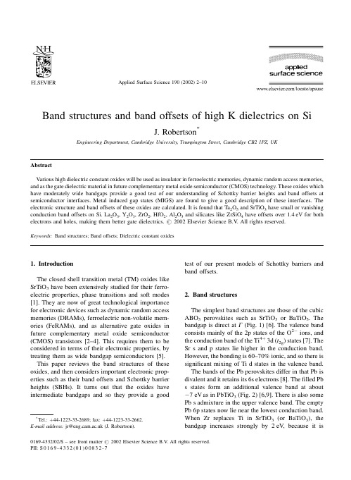
Band structures and band offsets of high K dielectrics on SiJ.Robertson *Engineering Department,Cambridge University,Trumpington Street,Cambridge CB21PZ,UKAbstractVarious high dielectric constant oxides will be used as insulator in ferroelectric memories,dynamic random access memories,and as the gate dielectric material in future complementary metal oxide semiconductor (CMOS)technology.These oxides which have moderately wide bandgaps provide a good test of our understanding of Schottky barrier heights and band offsets at semiconductor interfaces.Metal induced gap states (MIGS)are found to give a good description of these interfaces.The electronic structure and band offsets of these oxides are calculated.It is found that Ta 2O 5and SrTiO 3have small or vanishing conduction band offsets on 2O 3,Y 2O 3,ZrO 2,HfO 2,Al 2O 3and silicates like ZrSiO 4have offsets over 1.4eV for both electrons and holes,making them better gate dielectrics.#2002Elsevier Science B.V .All rights reserved.Keywords:Band structures;Band offsets;Dielectric constant oxides1.IntroductionThe closed shell transition metal (TM)oxides like SrTiO 3have been extensively studied for their ferro-electric properties,phase transitions and soft modes [1].They are now of great technological importance for electronic devices such as dynamic random access memories (DRAMs),ferroelectric non-volatile mem-ories (FeRAMs),and as alternative gate oxides in future complementary metal oxide semiconductor (CMOS)transistors [2±4].This requires them to be considered in terms of their electronic properties,by treating them as wide bandgap semiconductors [5].This paper reviews the band structures of these oxides,and then considers important electronic prop-erties such as their band offsets and Schottky barrier heights (SBHs).It turns out that the oxides have intermediate bandgaps and so they provide a goodtest of our present models of Schottky barriers and band offsets.2.Band structuresThe simplest band structures are those of the cubic ABO 3perovskites such as SrTiO 3or BaTiO 3.The bandgap is direct at G (Fig.1)[6].The valence band consists mainly of the 2p states of the O 2Àions,and the conduction band of the Ti 4 3d (t 2g )states [7].The Sr s and p states lie higher in the conduction band.However,the bonding is 60±70%ionic,and so there is signi®cant mixing of Ti d states in the valence band.The bands of the Pb perovskites differ in that Pb is divalent and it retains its 6s electrons [8].The ®lled Pb s states form an additional valence band at about À7eV as in PbTiO 3(Fig.2)[6,9].There is also some Pb s admixture in the upper valence band.The empty Pb 6p states now lie near the lowest conduction band.When Zr replaces Ti in SrTiO 3(or BaTiO 3),the bandgap increases strongly by 2eV,because itisApplied Surface Science 190(2002)2±10*Tel.: 44-1223-33-2689;fax: 44-1223-33-2662.E-mail address:jr@ (J.Robertson).0169-4332/02/$±see front matter #2002Elsevier Science B.V .All rights reserved.PII:S 0169-4332(01)00832-7controlled by the energy of the Zr d states.In contrast,in PZT,the Pb 6p states form the conduction band minimum,so the gap barely increases from 3.3to 3.7eV [10].It is recognised that the resonant covalence of Ti-d/O-p states is the origin of ferroelectricity in SrTiO 3type perovskites [11].In Pb perovskites,there is additional resonant covalence between Pb s and O p states which increases the ferroelectric polarity.SrBi 2Ta 2O 9is a layered crystal built from perovs-kite blocks separated by Bi 2O 2layers.It turns out that the Bi s and p states form the highest valence band and lowest conduction bands,respectively,while the ferro-electric response originates mainly from the TaO 3perovskite blocks [12].There is therefore an interest-ing separation of the functionality onto the Ta and Bi sub-lattices.Cubic ZrO 2has the ¯uorite structure.It has a simple band structure,as shown in Fig.3.The O p states form the valence band with a maximum at X [13].The conduction band minimum is at G ,and consists of Zr d states.The Zr d x 2Ày 2and d z 2states lie below the d xy states.The Zr s state lies midway between these at G ,but it disperses rapidly upwards.2.1.Models of Schottky barriers and semiconductor heterojunctionsThe band line-up of two semiconductors is deter-mined,like the SBH of a semiconductor on a metal,by charge transfer across the interface and the presence of any dipole layer at the interface.The charge transfer is that between the metal and the interface states of the semiconductor (Fig.4)[14].The charge transfertendsFig.1.Band structure of BaTiO 3calculated by pseudo-potential method [6].J.Robertson /Applied Surface Science 190(2002)2±103to align the Fermi level E F of the metal to the energy level of the interface states.The SBH for electrons f n between a semiconductor S and a metal M is f n S F M ÀF S F S Àw S(1)Here,F M is the work function of the metal,F S the energy of the semiconductor interface states,w S the semiconductor's electron af®nity (EA)and S the Schottky pinning parameter.S is given by [15]S11 e 2N d =ee 0(2)where e is the electronic charge,e 0the permittivity of free space,N the areal density of the interface states and d their decay length in the semiconductor.The dimensionless pinning factor S describes if the barrieris `pinned'or not.S varies between the limits S 1for unpinned Schottky barriers,and S 0for `Bardeen'barriers pinned by a high density of interface states in which the SBH is f n F S Àw S .There are numerous models of the origins of inter-face states,both intrinsic and extrinsic.In the intrinsic model originating from Bardeen and Heine,a semi-in®nite semiconductor in contact with a metal pos-sesses intrinsic states which are now called metal-induced gap states (MIGS)by Tersoff [14].F S is then the charge neutrality level (CNL)of the interface states,de®ned as the energy above which the states are empty for a neutral surface [16±18].On the other hand,the extrinsic models stress that the metal can react with the semiconductor [19].Brillson correlated the heat of reaction with S .This reaction maycreateFig.2.Band structure of PbTiO 3calculated by pseudo-potential method [6].4J.Robertson /Applied Surface Science 190(2002)2±10interface defects such as vacancies,whose gap states can pin the metal Fermi level,as noted by Spicer [20]and Dow [21].These models were supported by theobservation that pinning occurs even for monolayer coverage of metal,before the MIGS could be estab-lished.It is now believed that,overall,the intrinsic model gives a better description of Schottky barriers,because intrinsic states have a larger pinning dipole,N d ,than surface defects.The pinning parameter S has been in¯uential in our empirical understanding of Schottky barriers.Some years ago,Kurtin et al.[22]noted that S seemed to vary sharply with the ionicity of semi-conductor (Fig.5),from near 0for low ionicity semiconductors like Si and GaAs to 1for higher ionicity solids like SiO 2,SrTiO 3and KTaO 3.S is a dimensionless slope of barrier height to metal work function,S@f n @F M(3)Fig.3.Band structure of ZrO 2calculated by pseudo-potential method[6].Fig.4.Schematic diagram of SBHs.J.Robertson /Applied Surface Science 190(2002)2±105However,Louie [23]and Schluter [24]noted that Kurtin [22]had actually correlated the barrier heights to S H :S H@f n @X(4)which is the slope of barrier height to the Pauling electronegativity of the metal,and not the dimension-less S in (4).The work function and electronegativity vary roughly as [25,26]:F M 2:27X M 0:34(5)Thus,S H 2:27S ,and the Schottky limit should be S H 2:27.The data rarely reach this limit and Schluter [24]observed that S had a better correlation with the dielectric constant of the semiconductor e 0.Empiri-cally,Mo Ènch [14,27]found that S varied with e I as S11 0:1 e I À1 2(6)Certain materials are key tests of Schottky barriermodels.Diamond and xenon [14,28]have zero ioni-city but small e I ,and so their large S values show that S depends on e not on ionicity.This is tested by plotting log 1= S À1 against log e I À1 as in Fig.6.The wide gap oxides provide another key test,because they have intermediate e I values.SrTiO 3and KTaO 3were taken as high ionicity solids in the original Kurtin plot,with S H $1.However,this wasbefore data was actually known.When data [29]became available for SrTiO 3,showing S lying between 0.25and 0.4(Fig.6),it was clear that S is much lower.SrTiO 3falls well on the trend in Fig.3.The reason for this is that the SBHs depend on e I .e I is controlled by the states closest to the bandgap [5].In SrTiO 3,these are the moderately ionic Ti±O states of Ti±O bonds,not the highly ionic Sr±O states which lie well away from the gap and provide a much smaller contribution to e I .This can be seen in the partial density of states (DOS)of SrTiO 3in Fig.6.Thus,SrTiO 3and KTaO 3were misplaced in Fig.5as highly ionic solids.A lesser point is that the moderate value of S of SrTiO 3clearly correlates with e I ,and not with the low frequency dielectric constant e 0,which has a very large value for ferroelectrics and would give S %0from (6).SrTiO 3also serves as an evidence against the defect model,in that the barrier lies some way into the gap,not at the conduction band edge where the O vacancy states lie and would cause pinning.In sum-mary,the MIGS model of Schottky barriers holds for a wide range of solids of various ionicity and dielectric constants [5].The band alignment between two semiconductors is controlled by charge transfer and interface dipoles,just as Schottky barriers [30].For no dipoles,the Schottky limit,the conduction band offset isgivenFig.5.Schottky barrier pinning factor S H in the (incorrect)model of Kurtin etal.Fig. 6.Log±log plot of 1= S À1 vs.e I À1for various semiconductors and insulators to verify the MIGS model of Schottky barrier pinning factor S .6J.Robertson /Applied Surface Science 190(2002)2±10by the difference in their electron af®nities,the `elec-tron af®nity rule'.A similar idea was that for no charge transfer,the band line-ups are derived by placing each semiconductor's band on an absolute energy scale such as those of the free atom energy levels [31].Tersoff [16]showed that the band offset between two semiconductors a and b is controlled by interface dipoles as in the Schottky barrier,and so the conduc-tion band offset is given by f n w a ÀF CNL ;a À w b ÀF CNL ;bS F CNL ;a ÀF CNL ;b(7)The offsets are now described by aligning the CNLs of each semiconductor,modi®ed by the S factor.For simple semiconductors like Si,e I is large,and so S is small and the third term was negligible in the original formulation,but it is retained here for wide gap oxides.For strong pinning,the alignment is just given by the alignment of the two CNLs.The CNL energy below the vacuum level is a measure of the mean electronegativity of the semiconductor,in the same way that the work function of a metal is propor-tional to the metal's electronegativity.Thus,Eq.(7)says that the band alignment is the difference in electronegativity screened by the S factor.A wide ranging quantitative comparison found that the CNL models gives a good description of the band offsets [30].The CNL is the branch point of the semiconductor interface states.It is the integral of the Green's func-tion of the band structure,taken over the Brillouin zone [17],G E ZBZ N E H d H EE ÀE H0(8)Cardona and Christensen later provided a quicker method using a sum over special points of the Bril-louin zone [5,32].G E X i 1E ÀE i (9)2.2.Application to oxidesThe band alignments for the various wide gapoxides in contact with metal or silicon are found by calculating their CNLs and S parameters.The S factors are found from (6)using the experimental values of e Iand are shown in Table 1.The CNLs were found by calculating the oxide band structures by the tight-binding method [5,6,8,33].The tight-binding para-meters are found by ®tting to existing band structures [9,10,34],photoemission spectra and optical data [2,35±37].The CNLs for the various oxides are given in Table 1,together with the experimental values of their bandgaps and electron af®nities [2,38].SrTiO 3is an important oxide for future DRAM capacitor dielectrics.SrTiO 3is also the most studied system and the best test of our calculations.Fig.7compares the predicted SBHs of SrTiO 3on various metals with the experimental values [30,39±43].The experimental data are quite scattered but are quite consistent with S !1and our calculated value of 0.28.This shows that SrTiO 3is a key oxide in the tests of Schottky barrier models.The calculated barrier height for SrTiO 3on Pt is 0.9eV ,which is close to the 0.8eV found by photoemission by Copel et al.[43].However we cannot account for the much larger S value found by Shimizu et al.[42].BaTiO 3has similar band offsets to SrTiO 3.PbTi x Zr 1Àx O 3or PZT is an important ferroelectric for non-volatile memories,optical memories and other applications.The predicted barrier height for Pt onTable 1Calculated values for various oxides of their CNL and conduction band (CB)offset with Si aGap (eV)EA (eV)CNL (eV)e I S CB offset (eV)SiO 290.9 2.250.86 3.5b Si 3N 4 5.3 2.1 4.10.51 2.4b Ta 2O 5 4.4 3.3 3.3 4.840.40.3BaTiO 3 3.3 3.9 2.6 6.10.28À0.1BaZrO 3 5.3 2.6 3.740.530.8TiO 2 3.05 3.9 2.27.80.180.05ZrO 2 5.8 2.5 3.6 4.80.41 1.4HfO 26 2.5 3.740.53 1.5Al 2O 38.81c 5.5 3.40.63 2.8Y 2O 362c 2.4 4.40.46 2.3La 2O 36c 2c 2.440.53 2.3ZrSiO 46.5 2.4 3.6 3.80.56 1.5SrBi 2Ta 2O 94.13.53.35.30.4aExperimental values [36,37]of the bandgap,EA [2,38],dielectric constant e I [37]are also given.In Eqs.(2)and (5),F S is the energy of the CNL below the vacuum level,in this table,it is its energy above the valence band.bExperimental values.cEstimated values.J.Robertson /Applied Surface Science 190(2002)2±107PZT (Pb 0.55Zr 0.45O 3)is 1.45eV ,which is close to the 1.5eV measured by Dey et al.[44].The electron barrier of Pt on PZT is larger than that on BST because its CNL lies lower in the gap.This is because of the different band structure of PZT,in which the Pb 6s and 6p states form the band edges and this tends to lower the CNL.The larger value of the hole barrier than the electron barrier means that PZT thin ®lms can have predominantly electron injection,even though bulk PZT tends to be p-type.SrBi 2Ta 2O 9(SBT)is an important ferroelectric for non-volatile memories [2,45].It does not suffer from the loss of switchable polarisation (fatigue)when used with Pt electrodes,which is a problem for PZT.Note that more recent optical data ®nd that the bandgap of SBT is 4.1eV [2].The Schottky barrier of Pt is predicted to be 1.2eV ,which is essentially the same as that found by photoemission [46].There is an important need for high dielectric constant oxides to act as gate oxides instead of silicon dioxide [3,4].This is because the SiO 2layer is now so thin (2nm),that it no longer acts as a good insulator because of direct tunnelling across it.The solution is to replace SiO 2with a thicker layer of a medium k oxide,with the same equivalent capacitance or `equivalence oxide thickness't ox .The oxides must also satisfy certain other conditions,including chemi-cal stability in contact with Si [47].This rules out Ti and Ta which both react with Si to form SiO 2.The other key requirement is that they act as barriers toboth electrons and holes [5,32].This requires that both their valence and conduction band offsets be over 1eV .There is presently considerable effort to identify the most effective oxide,from a choice of ZrO 2,HfO 2,La 2O 3,Y 2O 3,Al 2O 3and the silicates ZrSiO 4and HfSiO 4.The calculated CB band offsets with Si are given in Table 1and summarised in Fig.8.They are compared in Table 2with recent experimental values [48±53],which is seen to be in good agreement.The important feature of Ta 2O 5and SrTiO 3is that both of them have CB offsets on Si under 1eV ,in fact 0in the case of SrTiO 3.This prediction was recently con®rmed by photoemission data of Chambers et al.[48].This means that SrTiO 3or BST cannot be a good gate oxide.The calculated CB offset for Ta 2O 5is only 0.36eV for Ta 2O 5on Si.This is consistent with recent photoemission data of Miyazaki and Hirose [49].Data for Ta 2O 5gate FETS also showed only a small elec-tron barrier [50].The CB offsets for BST and Ta 2O 5and BST are small or negligible because the bandgap is quite small and the band offsets are so asymmetric.To increasetheparison of calculated and observed SBHs of SrTiO 3on variousmetals.Fig.8.Predicted band offsets of various oxides on Si.Table 2Comparison of calculated and experimental values [48±53]of conduction band offsets on SiCalculatedExperiment References Ta 2O 50.350Miyazaki SrTiO 3À0.1<0.1Chambers ZrO 2 1.4 1.4Miyazaki 2.0Houssa Al 2O 32.82.8Ludeke8J.Robertson /Applied Surface Science 190(2002)2±10CB offset,we must either increase the bandgap or lower the CNL.The gap can be increased by raising the TM d levels,by using4d or5d metals instead of3d metals or using group IIIB metals instead of group IV. We should use zirconates,not titanates.The gap of BaZrO3is2eV wider than BaTiO3.Its offset is0.8eV.A better strategy is to lower the CNL.The CNL is lowered if the metal valence is lowered from4to3. Indeed,in Y2O3and La2O3,the CNL is much lower in the bandgap.Y2O3and La2O3are the oxides with largest CB offsets for reasonable dielectric constants. ZrO2has a bandgap of5.8eV,which is slightly wider than BaZrO3,and it also has a lower metal/ oxygen stoichiometry.This gives a larger CB offset for ZrO2(1.4eV)than BaZrO3,and indeed one which is just high enough.HfO2is similar.The calculated CB offset of1.4eV for ZrO2compares with an experi-mental value of1.4eV from photoemission[51]and a value of2eV by internal photoemission[52].This CB offset is large enough for devices.Zirconium silicate ZrSiO4and hafnium silicate HfSiO4are glassy oxides with bandgaps of $6.5eV.ZrSiO4consists of chains of alternate edge-sharing ZrO4and SiO2tetrahedra,with addi-tional Zr±O bonds between the chains,leading to an overall six-fold Zr coordination.We estimate the bandgap of ZrSiO4to be6.5eV.The calculated CB offsets are1.5eV,slightly more than ZrO2.Al2O3has a bandgap of8eV close to SiO2but with a higher k($9).Its calculated CB offset is2.8eV, which compares exactly with that measured by Ludeke et al.[53].Overall,the agreement between the calculated and subsequent experimental values for CB offsets in Table2is surprisingly good.References[1]M.E.Lines,X.Glass,Ferroelectrics,Oxford UniversityPress,Oxford,1990.[2]J.F.Scott,Ferroelectrics Rev.1(1998)1.[3]G.D.Wilk,R.M.Wallace,J.M.Anthony,J.Appl.Phys.89(2001)5243.[4]A.I.Kingon,J.P.Maria,S.K.Streiffer,Nature406(2000)1032.[5]J.Robertson,J.Vac.Sci.Technol.B18(2000)1785.[6]P.W.Peacock,J.Robertson,Unpublished work.[7]L.F.Mattheis,Phys.Rev.B6(1972)4718.[8]J.Robertson,W.L.Warren,B.A.Tuttle,D.Dimos,D.M.Smyth,Appl.Phys.Lett.63(1993)1519.[9]R.D.King-Smith,D.Vanderbilt,Phys.Rev.B49(1994)5828.[10]J.Robertson,W.L.Warren,B.A.Tuttle,J.Appl.Phys.77(1995)3975.[11]R.E.Cohen,Nature358(1992)136.[12]J.Robertson,C.W.Chen,W.L.Warren,C.D.Gutleben,Appl.Phys.Lett.69(1996)1704.[13]R.H.French,S.J.Glass,F.S.Ohuchi,Y.N.Xu,W.Y.Ching,Phys.Rev.B49(1994)5133.[14]W.MoÈnch,Phys.Rev.Lett.58(1987)1260.[15]W.MoÈnch,Surf.Sci.300(1994)928.[16]A.W.Cowley,S.M.Sze,J.Appl.Phys.36(1965)3212.[17]C.Tejedor,F.Flores,E.Louis,J.Phys.C10(1977)2163.[18]J.Tersoff,Phys.Rev.Lett.52(1984)465.[19]J.Tersoff,Phys.Rev.B30(1984)4874;J.Tersoff,Phys.Rev.B32(1985)6989.[20]L.J.Brillson,Surf.Sci.300(1994)909.[21]W.E.Spicer,T.Kendelewicz,N.Newman,K.K.Chin,I.Lindau,Surf.Sci.168(1986)240.[22]R.E.Allen,O.F.Sankey,J.D.Dow,Surf.Sci.168(1986)376.[23]S.Kurtin,T.C.McGill,C.A.Mead,Phys.Rev.Lett.30(1969)1433.[24]S.G.Louie,J.R.Chelikowsky,M.L.Cohen,Phys.Rev.B15(1977)2154.[25]M.Schluter,Phys.Rev.B17(1978)5044;M.Schluter,Thin Solid Films93(1982)3.[26]W.Gordy,W.J.O.Thomas,Phys.Rev.24(1956)439.[27]H.B.Michaelson,J.Appl.Phys.48(1977)4729.[28]W.MoÈnch,Phys.Rev.Lett.58(1986)1260.[29]W.MoÈnch,Europhys.Lett.27(1994)479.[30]R.C.Neville,C.A.Mead,J.Appl.Phys.43(1972)4657.[31]W.A.Harrison,J.Vac.Sci.Technol.14(1977)1016.[32]M.Cardona,N.E.Christensen,Phys.Rev.B35(1987)6182.[33]E.T.Yu,J.O.McCaldin,T.C.McGill,Solid State Phys.46(1992)1.[34]J.Robertson,C.W.Chen,Appl.Phys.Lett.74(1999)1168.[35]G.M.Rignanese,X.Gonze,A.Pasquarello,Phys.Rev.B63(2001)104305.[36]R.H.French,J.Am.Ceram.Soc.73(1990)477.[37]E.D.Palik,Handbook of Optical Properties of Solids,V ol.1±3,Academic Press,New York,1985.[38]W.Schmickler,J.W.Schultze,in:J.M.O'Bockris(Ed.),Modern Aspects of Electrochemistry,V ol.17,Plenum Press, London,1986.[39]G.W.Dietz,W.Antpohler,M.Klee,R.Waser,J.Appl.Phys.78(1995)6113.[40]H.Hasegawa,T.Nishino,J.Appl.Phys.69(1991)1501.[41]K.Abe,S.Komatsu,Jpn.J.Appl.Phys.31(1992)2985.[42]T.Shimizu,N.Gotoh,N.Shinozaki,H.Okushi,App.Surf.Sci.117(1997)400;()T.Shimizu,N.Gotoh,N.Shinozaki,H.Okushi,Mat.Res.Soc.Symp.Proc.(2000).[43]M.Copel,P.R.Duncombe,D.A.Neumayer,T.M.Shaw,R.M.Tromp,Appl.Phys.Lett.70(1997)3227.[44]S.K.Dey,J.J.Lee,P.Alluri,Jpn.J.Appl.Phys.34(1995)3134.[45]C.A.Paz de Araujo,J.D.Cuchiaro,L.D.McMillan,M.C.Scott,J.F.Scott,Nature374(1995)627.[46]C.D.Gutleben,Appl.Phys.Lett.71(1997)3444.[47]H.J.Hubbard,D.G.Schlom,J.Mater.Res.11(1996)2757.J.Robertson/Applied Surface Science190(2002)2±109[48]S.A.Chambers,Y.Liang,Z.Yu,R.Dropad,J.Ramdani,K.Eisenbeiser,Appl.Phys.Lett.77(2000)1662.[49]S.Miyazaki,Appl.Surface Science(2002)``these proceed-ings''.[50]S.Miyazaki,M.Narasaki,M.Ogasawara,M.Hirose,Microelec.Eng.59(2001)373.[51]A.Chatterjee,et al.,IEDM Tech Digest,1998,p.777.[52]M.Houssa,M.Tuominen,M.Nailli,V.Afansev, A.Stesmans,J.Appl.Phys.87(2000)8615.[53]R.Ludeke,M.T.Cuberes,E.Cartier,Appl.Phys.Lett.76(2000)2886;D.J.Maria,J.Appl.Phys.45(1974)5454.10J.Robertson/Applied Surface Science190(2002)2±10。
零维、一维和二维ZnO纳米材料的应用研究进展

氧 化 锌 (ZincOxide,ZnO)是 ⅡⅥ 族 宽 带 隙 半 导 体材 料,其 禁 带 宽 度 为 3.37eV,激 子 结 合 能 为 60meV,具有高透明 性、抗 辐 射 稳 定 性、室 温 强 紫 外 激 发、环境友好和 低 成 本 等 性 质,同 时 ZnO 还 拥 有 丰 富 多彩的零 维、一 维 和 二 维 纳 米 结 构。 因 此,ZnO 在 光 学、光电子学、传感器、能 源 以 及 自 旋 电 子 学 等 领 域 有 着广泛的应用。
犃犫狊狋狉犪犮狋:ZnOasawidebandgapsemiconductornotonlyhasexcellentoptoelectronicproperties,but alsocontainsrich0D,1Dand2Dnanostructures.Basedonthe0D,1Dand2DZnOnanomaterials,the researchprogressofmainoptoelectronicdeviceapplication,includingphotocatalysis,gasdetectors,so larcells,photodetectors,lightemittingdiodes,lasers,piezoelectricdevicesandresistiverandom access memorywasnarratedsyntheticallyinthispaper.Thedifferencesofthreedimensionsinoptoelectronic applicationofZnOnanomaterialwerelaterallycomparativelyanalyzed,andtheadvantagesofdifferent dimensionsintheoptoelectronicdevicesweresummarized,finally,theproblemsintheapplicationof zincoxidenanomaterialswerealsoprospected,suchasthedifficultytoachieveptypedoping. 犓犲狔狑狅狉犱狊:ZnO;nanomaterial;optoelectronicdevice;deviceapplication
导电陶瓷
固相烧结法是一种制备陶瓷材料的传统方法,将陶瓷原料粉末混 合均匀后压制成形,在高温下无压(或有压)烧结,随炉冷却后便得 到所需的陶瓷材料。
王春华等人[6]采用常压法获得致密的碳化硅烧结体,体积密度为 3.12g/cm3, 电阻率为0.165Ω·m;该陶瓷在300~600℃温度范围内 表现出明显的负电阻率温度系数。为提高导电陶瓷的导电能力,常对 陶瓷进行掺杂。刘汉忠研究了Ce 掺杂La0.5-xCexBa0.5CoO3陶瓷时, 发现该陶瓷材料是一种电子、空穴和氧离子混合导电的陶瓷材料; La0.5-xCexBa0.5CoO3的x 在0.1~0.5 变化时,电阻率ρ随Ce的掺杂 量增加而单调上升。图2 给出了烧结温度为1080℃和1100℃时,样品 的室温电阻率ρ(mΩ/cm)与Ce的加入量x的关系。
吴敏艳等人[2]采用溶胶- 凝胶法制备了粒径为30~60nm 的超细 粉,采用速控烧结制度在较短的烧结时间里获得相对密度为98%、平 均晶粒度小于1μm 的致密陶瓷。王歆等人[3]用溶胶-凝胶法,在Al2O3 衬底上制备了导电性能优良的BaPbO3(BPO)导电薄膜。研究发现,升 高热处理温度和增加热处理次数使薄膜中Pb/Ba摩尔比降低和膜厚减
2.3 化学气相扩渗法
为改善陶瓷的导电性能,通常在制备前躯体时掺入其它元素,如 郝素娥等人[8]采用气相化学热扩渗的方法,使稀土元素有效地渗入到 钛酸铅陶瓷中,在陶瓷结构中形成了均匀、细小、弥散的形貌结构特 征;稀土扩渗使钛酸铅基陶瓷的导电性显著增强,其室温电阻率下降 为0.2Ω·m。
2.4 微波烧结法
3 SnO2 基导电陶瓷靶材的制备及应用性能表征 3.1 Sb∶SnO2(ATO)陶瓷靶材的制备
选用纯度为 99.99%氧化锡粉体(国药集团化学试剂有限公司 99.99%氧化锑粉体(国药集团化学试剂有限公司)为原料,采用Sb2O5 的掺杂量为6%(wt) 进行配样,选用无水乙醇作粘结剂,将得到的 SnO2混合粉末在无水乙醇充分球磨6小时(球磨机型号:XQM 型变频 行星式球磨机),接着在干燥箱80℃下烘干,保持一定的湿度,具有 好的流动性,然后采用型号为769YP-40C 粉末压片机进行成型,压成 φ56mm×6.5mm 的坯体,所得坯体再次采用冷等静压法压成靶材素 坯。最后采用常压、空气烧结方式,德国NaberTherm 公司的HTRV 系 列高温炉烧结。采用的是图5烧结方案进行烧结。此方案在200℃保温 30min,600℃保温60min,1000℃保温60min,然后升温到最终烧结温 度的1250℃保温300min,然后随炉冷却。采用此烧结程序符合物质的 烧结规律,在进入烧结初期时,在200℃保温半个小时,物料自由水 分更有利于挥发;在600℃保温一个小时,各种杂质例如有机物已经 完全挥发,更能让物质进入烧结期做充分准备;在进入烧结中期时, 在1000℃时进行保温一个小时,物质有完全充分的时间进入烧结中 期,缓慢进入烧结终点温度,最后在烧结终点温度1250℃时保温五个 小时,物质充分反应,这种烧结曲线更加符合物质的烧结模型,与文 献的报道是相似的。
【论文】半导体纳米材料论文fulltext2图文精
【关键字】论文BRIEF COMMUNICATIONPreparation and photoelectric properties of mesoporous ZnO filmsMing Ming Wu •Yue Shen •Feng Gu •Yi An Xie •Jian Cheng Zhang •Lin Jun WangReceived:24June 2009/Accepted:21October 2009/Published online:6November 2009ÓSpringer Science+Business Media,LLC 2009Abstract Mesoporous ZnO films doped with Ti 4?(M-ZnOhave been prepared by doping process and sol–gel method.The films have mesoporous structures and consist of nano-crystalline phase,as evidenced from small angle X-ray diffraction and high resolution transmission electron microscopy.The wide angle X-ray diffraction of M-ZnO films confirms that M-ZnO has hexagonal wurtzite structure and ternary ZnTiO3phases.Ultraviolet–visible transmittance spectra,absorbance spectra and energy gaps of the films were measured.The Eg of M-ZnO is intensity of M-ZnO centered at 380nm increases obviously with the excitation power,which is due to the doping process and enhanced emiss ion efficiency.M-ZnO thin films display a positive photovoltaic effect compared to mesoporous TiO 2(M-TiO 2films.Keywords Photoelectric propertiesÁMesoporous ÁZnO ÁTiO 21IntroductionIt has been recently shown that semiconducting mesoporous metal oxides,e.g.,SnO 2[1,2]or TiO 2[3],with large specific surface areas and uniform pore widths show interesting properties which are superior to non porous samples of the same metal oxides.Zinc oxide (ZnOis attracting tremendous research interest due to its vast spectrum properties and applications.ZnO is an n-type direct band-gap semiconductorwith E g =3.37eV and an exciton-binding energy of 60meV.It has been applied for light-emitting diodes [4–6],lasers [7],photovoltaic solar cells [8],UV-photodetectors [9]and sensors [10].Particularly,it has attracted great attention in Dye-sensitized solar cells (DSSC.To date,the highest solar-to-electric conversion effi-ciency of over 11%has been achieved with films that consist of mesoporous TiO 2nanocrystallites sensitized by ruth e-nium-based dyes [11].Besides the optical properties similar to TiO 2,ZnO has other advantages such as higher light absorbance below 400nm than TiO 2[12],improved elec-tronic transfer rate and hindered dark current generation [13,14].Nevertheless,ZnOnano structure electrodes seem to have insufficient internal surface areas,which limits their energy conversion efficiency at a relatively low level,for example,1.5–2.4%for ZnO nanocrystalline films [15–17],0.5–1.5%for ZnO nanowire films [18–20],2.7–3.5%for uniform ZnO aggregate films [21,22]and 5.4%for poly-disperse ZnO aggregates [8].In spite of a great deal of effort to successfully synthesize mesoporous ZnO powders successfully [23,24],however,many barriers still exist due to the intrinsic properties of zinc versus silicon.To the best of our knowledge,there were few reports about ordered mesoporous ZnO thin film prepared by wet chemical method.The main hurdles in the synthesis of well-ordered mesoporous ZnO are the high reactivity of Zn ion precursors toward hydro lysis [25]and difficulty for Zn to form the three-dimensional network structure of Zn-O as compared to Si and Ti [26].In this work,we report a highly reproducible synthetic method to produce thermally stable M-ZnO films through doping process and sol–gel method.Photoelectric proper-ties of M-ZnO films were studied and compared with M-TiO 2films,which can get the highest solar-to-electric conversion efficiency.ÁY.Shen (&ÁF.Gu Á Á ÁSchool of Materials Science and Engineering,Shanghai University,Shanghai 200072,Chinae-mail:yueshen@;J Sol-Gel Sci Technol (201053:470–474DOI 10.1007/s10971-009-2099-72ExperimentalThe Pluronic P123triblock co polymer(EO20PO70EO20 with a molar weightof5800was kindly donated by BASF. All other chemicals were of analytical grade and used as received.M-ZnOfilms were prepared by doping process and sol–gel method via the following procedure:1.6ml concentrated HCl was slowly added to0.17ml tetrabutyl titanate(TBOT, [98%purityand2.085g zinc acetate dihydrate(Zn(Ac2, [99%purityat room temperature under vigorous stirring. Separately,0.75g P123wasfirst dissolved in8.3ml 1-butanol([99%purity,then added to the HCl/TBOT/ Zn(Ac2solution.At last,2ml acetylacetone(AcAcwas added.This solution was subsequently aged with stirring at room temperature for6h.The molar ratio of P123/1-buta-nol/Zn(Ac2/TBOT//AcAcwas0.013:9:0.95:0.05:2:2.M-ZnOfilms were prepared by spin coating the freshsolution onto Indium tin oxides(ITOsubstrate at900rpm for10s and3,300rpmfor20s.The as-synthesizedfilms were aged at40°C for1days and then annealed at120°C for5h at vacuum.The thickfilms were prepared by repeating the above stepsfor5times.Thefilms were sub-sequently calcined at a rate of1K min-1to350°C for5h. ITO glasses had been eroded to form plan electrodes before the spin coating process,and cleaned successively in de-ionized water,acetone and ethanol,for10min each.For ease of comparison,we prepared mesoporous TiO2(M-TiO2thin films using the same process.Themolar ratio of P123/ 1-butanol/TBOT/HCl/AcAc was0.013:9:1:2:2.The thick-ness of thinfilms is about100nm.Thefilms were characterized by(X-ray diffractometer, RigakuD/MAX-2550,Tokyowith Cu K a radiation (k=1.54056A˚,operated at40kV and200mA.The small angle scanning range was from0.5°to3°with a scanning rate of0.25°min-1.Transmission electron microscopic(TEMimages of M-ZnO thinfilms were obtained using Japan JEM-2010F microscope operating at an acceleration voltage of200kV.A JASCO V570spec-trophotometer was used to measure the optical spectra of the thinfilms.PL spectra were measured at room temper-ature with a spectrometer(Horiba Jobin Yvon HR800 using the excitation source of the325nm line of a He-Cd laser.Current-voltage measurements were carried out by semiconductor characterization system(Keithley4200, Americawith a tungsten lamp(250W.All measurements were performed at room temperature in air.3Results and discussionsSAXRD and HRTEM are two typical ways to investigate the order properties of mesoporous materials.The SAXRD patterns of M-ZnO and M-TiO2thinfilms are shown in Fig.1,and illustrate characteristic peaks at2h=0.62°and 0.75°,respectively,suggesting that the M-ZnO and M-TiO2thinfilms exhibited mesoporous structure.The diameter/d value,determined as distance between meso walls,is calculated from the2h values of the characteristic peaks by the Bragg equation. Further structural characterization of M-ZnO was per-formed using HRTEM and is shown in presents a honeycomb-like porous structure and the pore size is conforming to the results of SAXRD.In image(b, there are obviou s lattice fringes,which indicate thefilms have nano-crystalline phase structure.Figure3shows the wide angle X-ray diffraction patterns of M-ZnO thickfilms(on ITO substratesand ITO sub-strates,respectively.It can be seen that M-ZnO thickfilms exhibit hexagonal wurtzite structure and ternary ZnTiO3 phases,together.Yet no peaks corresponding to titanium and/or titanium oxide were detected.The crystal latticeconstants of M-ZnO calculated from the wide-angle X-ray diffraction are a=3.243A˚and c=5.190A˚,which are close to the card JCPDS No.36-1451,a=3.250A˚and c=5.207A˚.The differences result from the introduction of Ti ion in ZnO,because the Ti4?radius(0.68A˚is smaller than that of Zn2?(0.74A˚.The slight change of lattice parameters of M-ZnOconfirms that the Ti io ns have been incorporated into the ZnO lattice.Ultraviolet-visible(UV/vistransmittance spectra of M-ZnO and M-TiO2thinfilms were measured in Fig.4. Compared to the M-TiO2thinfilm,the fundamental transmittance edge of the M-ZnO thinfilm shows a blue shift fro m350to300nm.The inset graph is the absorbance spectra of M-ZnO and M-TiO2thinfilms.It illustrates that the absorption rate of M-ZnO is greater than that of M-TiO2in the visible range,suggesting the highzinc Fig.1SAXRD patterns of(aM-ZnO and(bM-TiO2content M-ZnO composite material can increase the light-harvesting capability as photoelectrode film.The plot of (a h m 1/2versus h m of M-ZnO and M-TiO 2films is shown in Fig.5,where a is the absorption coefficient,h m is the photon energy.Following the well-known Tauc function:(a h m 1/2µ(h m -Egand extrapolating the linear portion to (a h m 1/2=0,the optical-gap energy (Egcan be deter-mined.It could be found that the Eg of M-ZnO and M-TiO 2were 3.25and 3.37eV,respectively.Figure 6shows the room-temperature PL spectra of M-ZnO thick films as a function of the excitation power density.The five excitation power intensities are 2,20,50,100,and 200mW,respectively.The spot radius is 1l m.Dominant emission peaks of M-ZnO centered at 380nm,corresponding to 3.26eV,are ascribed to direct electron-hole recombination which should be equal to the M-ZnO band gap.It is worth noting that there is asignificantFig.2TEM images of a M-ZnO (50,0009and b M-ZnO (200,0009Fig.3The wide angle X-ray diffraction of M-ZnO thick films and ITOsubstratesFig.4Transmittance spectra of (a M-ZnO and (b M-TiO 2(inset:UV/vis absorbance spectra of (a M-ZnO and (b M-TiO 2Fig.5Energy gap (Egof (a M-ZnO and (b M-TiO 2increase of PL intensity of M-ZnO thick films at 380nm as compared to the visible bands emission with excitation powers increasing from 2to 200mW.This result is con-sistent to literature [27]and can be expected to be caused by the doping process due to enhanced emission efficiency from free exciton emission [27].For M-ZnO films,Ti atoms occupy Zn atom sites in the lattice of ZnO.When incident UV light excite the carriers in the films,the photocarriers may escape more easily from Ti ions than from Zn ions,which leads to the quick diffusion of excitons and increased exciton concentration in the M-ZnO films.Current-voltage properties of M-ZnO and M-TiO 2thin films were tested in dark and under irradiation for 5s with a tungsten lamp (250W,height to the film was 15cm.As shown in Fig.7b,photoconductivity of the M-TiO 2thin film was 6.023910-10S and dark conductivity was 1.070910-9S at bias voltage of 1V,photoconductivitydecreased about 1.8times under irradiation compared with that in thedark.However,under the same irradiation condition,it was interesting to find that the M-ZnO thin film exhibits a positive p hotovoltaic effect.Photoconduc-tivity of the M-ZnO thin film reached 9.718910-7S while dark conductivity was 3.256910-7S,photocon-ductivity increased about 3times as shown in TiO 2was widely used in DSSC,it has a low electron transfer rate and high combination rate of the pair of excited electrons [8,9],which induced a negative pho-tovoltaic effect itself.While ZnO has very high electron mobility,which is about 155cm 2V -1s -1[28],ZnO materials can improve the electronic transfer rate and hinder the dark current generation [13,14].Furthermore,it contains some intrinsic defects,which can act as capture centers of photoelectrons andthereby stop the recombina-tion of photoelectrons and photo-holes.This may improve the energy conversion efficiency of M-ZnO in DSSC.4ConclusionIn conclusion,M-ZnO films doped with Ti 4?were pre-pared by sol–gel and spin coating method.Eg of M-ZnO is 3.25eV,which is smaller than that of bulk ZnO.M-ZnO films exhibit hexagonal wurtzite structure and ternary ZnTiO 3phases.The PL intensi ty of M-ZnO centered at 380nm is increased obviously with the excitation power,which is expected to be caused by enhanced emission efficiency from free excitonemission.Current-voltage properties of M-ZnO films display a positive photovoltaic effect and indicate the promising applications in DSSC.Acknowledgments The work was supported by Innovation Pro-gram of Shanghai Municipal Education Commission (08YZ08,AM and other Research Foundation of Shanghai City Committee of Sci-ence and Technology(0852*******,0752nm016,07JC14058and Shanghai Leading Academic Disciplines(S30107.We thank Dr.Qiang Li,Bo Lu and Jian Huang for their assistance in the measurement at Shanghai University.References1.Wagner T,Kohl CD,Fro¨ba M,Tiemann M (2006Sensors 6:3182.Hyodo T,Abe S,Shimizu Y,Egashira M (2003Sens Actuators B 93:5903.Choi H,Stathatos E,Dionysiou DD (2006Appl Catal B 63:604.Keem K,Jeong DY,Kim S,Lee MS,Yeo IS,Chung U,Moon JT (2006Nano Lett 6:14545.Konenkamp R,Word RC,Godinez M (2005Nano Lett 5:20056.Spanhel L (2008J Sol-Gel Sci Technol 39:77.Kim YJ,Shang HM,Cao GZ (2006J Sol-Gel Sci Technol 38:798.Zhang QF,Chou TP,Russo B,Jenekhe SA,Cao GZ (2008Angew Chem 120:24369.Monroy E,Omnes F,Calle F (2003Semicond Sci Technol 18:3310.Yan CL,Xue DF (2007J Alloys Compounds431:241Fig.6PL spectra of M-ZnO thick films with various excitation power densities at roomtemperatureFig.7Current-voltage characteristics of a M-ZnO and b M-TiO 2(filled square in dark,(filled triangle under irradiation11.Gra¨tzel M(2005Inorg Chem44:684112.Sakthivel S,Neppolian B,Shankar MV,Arabindoo B,Palanich-amy M,Murugesan V(2003Sol Energy Mater Sol Cells77:6513.Mane RS,Lee WJ,Pathan HM(2005J Phys Chem B109:2425414.Wang ZS,Huang CH,Huang YY(2001Chem Mater13:67815.Otsuka A,Funabiki K,Sugiyama N,Yoshida T(2006Chem Lett35:66616.Zeng LY,Dai SY,Xu WW,Wang KJ(2006Plasma Sci Technol8:17217.Lee WJ,Suzuki A,Imaeda K,Okada H,Wakahara A,Yoshida A(2004Jpn J Appl Phys43:152w M,Greene LE,Johnson JC,Saykally R,Yang PD(2005Nat Mater44:5519.Baxter JB,Aydil ES(2005Appl Phys Lett86:05311420.Pasquier AD,Chen HH,Lu YC(2006Appl Phys Lett89:321.Zhang QF,Chou TP,Russo B,Jenekhe SA,Cao GZ(2008AdvFunct Mater18:165422.Chou TP,Zhang QF,Fryxell GE,Cao GZ(2007Adv Mater19:258823.Wagner T,Waitz T,Roggenbuck J,Fro¨ba M,Kohl CD,TiemannM(2007Thin Solid Films515:836024.Polarz S,Orlov AV,Schu¨th F,Lu AH(2007Chem Eur J13:59225.Soler-Illia GJ,Sanchez C,Lebeau B,Patarin J(2002Chem Rev102:409326.Yang PD,Zhao DY,Margolese DI(1999Chem Mater11:281327.Zhang Y,Zhang ZY,Lin BX,Fu ZX,Xu J(2005J Phys Chem B109:1920028.Kaidashev EM,Lorenz M,von Wenckstern H,Rahm A,Sem-melhack H-C,Han K-H,Benndorf G,Bundesmann C,Hochmuth H,Grundmann M(2003Appl Phys Lett82:3901此文档是由网络收集并进行重新排版整理.word可编辑版本!。
ZnO应用情况
ZnO纳米结构的实际应用
染料敏化ZnO纳米线阵列太阳能电池 纳米尺寸效应发光之LED、OLED 纳米表面性质应用之OLED等器件 电极、空穴 注入层、传输层、缓冲层等
红外反射膜 选择投射莫 气敏元件
电炉、干燥箱观察窗
太阳光聚热器
ZnO半导体器件
ZnO-LED
–
MIS结构、异质结结构、同质结结构、PIN结构、 多量子阱结构 多为PV型,常规MSM结构
紫外光电探测器
–
紫外激光器 ZnO基TFT(IGZO TFT) ZnO压电、气敏、压敏器件等
ZnO的纳米结构
Wurtzite ZnO: spontaneous polarization
ZnO的能带结构
ZnO 直接带隙 宽禁带3.37eV 由于六方纤锌矿结构对称性 较低,ZnO能带较复杂。其 价带导带的能隙有O-2p,Zn4s态决定 对ZnO能带的深入研究最早 是Thomas,后来Shindo和 Lambrecht等人作了进一步研 究之后,人们对ZnO的能带 结构做了更深入的探索,为 ZnO能带工程打下良好基础。
ZnO透明导电膜的应用
LCD,ELD,ECD,PHD
OPB 摄像元件 图像传感器 遮光玻璃 输入画面用开关,接触式面板,触摸屏 防静电膜 电磁波屏蔽
透明电极
电学 方面 的应 用
仪表窗口
防雾防霜玻璃:汽车,飞机挡风玻璃,相机,滑雪眼镜
面发热膜
光学 方面 的应 用
晶带轴
In Situ Growth of Self-Assembled and Single In2O3Nanosheets onthe Surface of Indium GrainsHeqing Yang,*,†Ruigang Zhang,†Hongxing Dong,†Jie Yu,†Wenyu Yang,†andDichun Chen‡Key Laboratory of Macromolecular Science of Shaanxi Pro V ince,School of Chemistry and MaterialsScience,Shaanxi Normal Uni V ersity,Xi’an710062,China,and Ad V anced Material Analysis and TestCenter,Xi’an Uni V ersity of Technology,Xi’an710048,ChinaRecei V ed January7,2007;Re V ised Manuscript Recei V ed May15,2008ABSTRACT:Self-assembled In2O3nanosheet networks andflowerlike nanoarchitectures,as well as single In2O3nanosheets,have been grown in situ on indium substrate by heating indium grains at900-950°C under theflow of O2in the presence of a small quantity of P2O5.The as-synthesized In2O3nanosheets were characterized by transmission electron microscopy,scanning electron microscopy,and Raman spectrum.It was found that the In2O3nanosheets were single crystals with body-centered cubic structure and dimensions of about0.5-3µm.A possible mechanism for the In2O3nanosheet growth was also proposed on the basis of the results of the present and previous works.This mechanism not only can explain all the experimental observations but also helps to clarify the growth mechanism of other nanostructures in the gas phase.A strong and narrow photoluminescent(PL)peak at428nm was observed from the nanosheets,which is attributed to radiative recombination between an electron on an oxygen vacancy and a hole on an indium-oxygen vacancy center in the In2O3nanosheets.1.IntroductionSynthesis of different dimensional(D)nanostructures,such as0D quantum dots,1D nanowires and nanotubes,or2D nanosheets and nanodisks are of great importance in studying the physical properties of nanomaterials or constructing func-tional nanodevices.1Indium oxide(In2O3),an n-type semicon-ductor with a wide bandgap of about3.6eV,has been widely used as window heater,solar cell,andflat-panel display materials2and gas sensors.3Since the discovery of indium oxide nanobelts in2001,4research in In2O3nanostructures,including nanowires,nanotubes,nanobelts,octahedrons,nanocubes,and core-shell nanoparticles has been rapidly expanded due to their potential application in high sensitivity sensor,optoelectronic,field emission,and electronic devices.The indium oxide nanowires have been used to fabricatedfield-effect transistors,5,6 nanoscale chemical sensors,7and biosensing devices.8Up to now,many kinds of In2O3nanostructures have been synthesized via thermal evaporation of In2O3,chemical vapor deposition(CVD),pulsed laser deposition(PLD),and wet chemical methods.In2O3nanobelts were synthesized via a thermal evaporation of In2O3powders at1400°C4or via a CVD using thermal oxidation reactions of In.9In2O3nanowires can be obtained by the CVD of thermal oxidations10–12and reductions,6,13,14by a laser ablation of InAs target,15or by triblock copolymer and porous alumina template methods.16 Additionally,single-crystalline In2O3nanotubesfilled with metallic In,17In2O3nanocrystal chains,and nanowire networks18 were synthesized by evaporating a mixture of In/In2O3or C/In2O3.Hollow In2O3nanotubes were grown in porous alumina membranes by a sol-gel process.19Aligned1D In2O3structures with a triangular cross-section were synthesized by a metal-organic chemical vapor deposition method(MOVCD).20In addition to the quasi-1D nanostructures,0D quantum dots such as quasi-monodisperse In2O3nanoparticles,21,22nanocubes,23In2O3octahedron,24,25and highly ordered In2O3coated In core-shell nanoparticles26were prepared via wet chemical methods,21–23CVD,24,25and a three-step oxidation process of In nanoparticle arrays.26However,to our knowledge,synthesis of2D In2O3nanostructures except for thinfilms has not been reported until now.Herein we report the synthesis of self-assembled and single In2O3nanosheets by an in situ thermal oxidation method.These sheet-like nanostructures were directly grown on the surfaces of indium grains by heating indium metal at900-950°C in an oxygen gas atmosphere in the presence of a small quantity of pared with CVD,MOCVD,and PLD,this procedure does not include In or In2O vapor transport and condensation processes and does not require very high temperature and low pressure.Growth mechanism and photoluminescence of the In2O3nanosheets were investigated in detail.2.Experimental Procedures2.1.Sample Preparation.The In2O3nanosheets were synthesized by a simple thermal oxidation of indium metal in a conventionalhorizontal tube furnace.In a typical experiment,In metal grains(purity99.999%)were treated in an aqueous1.0M HCl solution for30s andthen washed with absolute ethanol in an ultrasonic bath for15min.The grain was placed on a silicon wafer,and the silicon wafer wasplaced in a quartz boat containing a small quantity of P2O5(formed byheating a quartz boat containing about2-5mg of red phosphorus to500°C and then maintaining it at500°C for0.5h in an O2gasatmosphere).The boat was placed at the center of a quartz tube thatwas inserted in a horizontal tube furnace,where the temperature andgrowth time were controlled.Prior to heating,high-purity N2(99.999%)was introduced into the quartz tube with a constantflow rate of3.0L/h to purge the O2inside.After20min,the system was heated to900°C for60min under a constantflow of N2gas at a rate of1.0L/h. Afterward,1.0L/h O2was introduced into the chamber,and thetemperature was kept at900°C for2h.After the system cooled toroom temperature under a constantflow of N2gas at a rate of1.0L/h,a large amount of ashen products were found on the surface of theindium grains.2.2.Characterization.The synthesized products were characterized and analyzed by X-ray diffraction(XRD;Rigaku DMX-2550/PC X-ray diffractometer),Raman spectra(Jobin Yvon LabRAM HR800and*Corresponding author.Fax:+86-29-85307774.Tel:+86-29-85303943.E-mail address:hqyang@.†Shaanxi Normal University.‡Xi’an University of Technology.10.1021/cg070019e CCC:$40.75 XXXX American Chemical SocietyPublished on Web 07/23/2008Nicolet Alemga dispersive Raman spectrometer),scanning electron microscopy (SEM;FEI Quanta 200),and high-resolution transmission electron microscopy (HRTEM;JEOL JEM-3010at 300kV).Samples for HRTEM were prepared by dispersing a powdered In 2O 3product on a carbon-coated copper grid.An energy-dispersive X-ray spectros-copy (EDS)facility attached to the SEM and TEM was employed to analyze the chemical composition.Photoluminescent (PL)spectra were measured at room temperature in an Edinburgh FLS920fluorescence spectrophotometer with a Xe lamp using excitation at 380nm.3.Results and DiscussionFigure 1a -c shows typical SEM images of as-prepared samples grown at 900°C for 2h at low and high magnifications.These In 2O 3nanosheets were randomly and fairly uniformly distributed on the surface of the In grain.Figure 1c clearly shows that In 2O 3nanosheets are oriented upward with respect to the underlying substrate and have irregularly shaped morphologies with maximum dimension of about 0.5-3.0µm on the bottom,gradually narrowing to the top.The minimum thickness of the In 2O 3sheets on the top is tens of nanometers.In addition to the dispersed In 2O 3nanosheets,a small quantity of intercrossed In 2O 3nanosheet networks are also observed in some areas on the surface of the In grains.The typical morphology of these self-assembled In 2O 3nanosheets is shown in Figure 2.Figure 2a-b shows the low-and high-magnification SEM images,respectively.Figure 2b clearly shows that the network is constructed of nanosheets with heights ranging from 0.5to 1.2µm.The nanosheets intercross with each other to form complicated networks.When the reaction temperature was increased from 900to 950°C,a few interesting flowerlike In 2O 3nanoarchitectures were observed on the surface of the In grains.Typical SEM micrographs of the flowerlike In 2O 3nanoarchi-tectures at low and high magnifications are presented in Figure 3a,b.From Figure 3a,b,it is evident that In 2O 3nanoflowers consist of sheetlike nanostructures.The In 2O 3nanosheets possessmainly fan-shaped morphologies and are 0.5-5.5µm in length and 0.6-3.2µm in height.Figure 4a shows the XRD pattern of the samples grown at 900°C for 2h in an O 2gas atmosphere.Sixteen peaks at 2θ)30.5°,32.8°,35.3°,37.6°,41.7°,43.6°,45.5°,49.1°,50.9°,52.8°,56.0°,59.0°,60.5°,62.1°,63.5°,and 64.4°are observed from Figure 4a.According to JCPDS card no.06-0461,the products are In 2O 3with body-centered cubic structure,and these peaks are assigned to (222),(321),(400),(411),(332),(422),(431),(521),(440),(433),(611),(541),(622),(631),(444),and (543)diffraction lines of cubic In 2O 3phases,respectively.RamanFigure 1.SEM images of as-prepared samples grown at 900°C for 2h at differentmagnifications.Figure 2.Low-(a)and high-magnification (b)SEM images of the intercrossed In 2O 3nanosheetnetworks.Figure 3.Low-(a)and high-magnification (b)SEM micrographs of the flowerlike In 2O 3nanoarchitectures grown at 950°C for 2h.Figure 4.XRD pattern (a)and Raman spectrum (b)of the samples grown at 900°C for 2h.B Crystal Growth &Design,Vol.xxx,No.xx,XXXX Yang et al.scattering,due to its sensitivity to crystallization in nanostruc-tures,was also measured for the In 2O 3nanosheets.Figure 4b shows the Raman spectrum of the samples grown at 900°C for 2h excited with an Ar +laser at 514nm at room temperature.The five peaks at 126,301,358,489,and 622cm -1can be identified to be those of the cubic In 2O 3.27XRD and Raman indicate that the products obtained are In 2O 3nanosheets with cubic structure.The characterization of individual In 2O 3nanosheets was achieved in further detail using TEM.Figure 5a shows the TEM image of a quasi-rectangular In 2O 3nanosheet.The nanosheet is 650nm in length and 520nm in width.The contrast on a whole sheet is inhomogenous,which indicates that the thick-nesses of the sheet at the root and the center are greater than that at the top and side edges,as observed by SEM.The corresponding selected area electron diffraction (SAED)pattern is shown in Figure 5b;it can be indexed as a cubic In 2O 3along the [125]axis,consistent with the XRD and Raman results.The HRTEM image of the In 2O 3nanosheet is displayed in Figure5c.The fringe spacing is about 0.42nm,corresponding to the (121j )crystal planes of the cubic In 2O 3.The chemical composi-tion of the In 2O 3nanosheet was verified by an EDS facility attached to the TEM.The EDS data curve is shown in Figure 5d,in which In,O,and Cu elements were marked.The Cu-related peak is due to the presence of the Cu grids.So,the nanosheet consists of indium and oxygen.These results indicate that the nanosheets are a single-crystalline with body-centered cubic structure.To identify whether there was P 2O 5on the surface of the In 2O 3nanosheets,an EDS facility attached to the SEM was employed to analyze the chemical composition of the In 2O 3nanosheets obtained by heating indium grains at 900°C for 2h in an O 2gas atmosphere in the presence of a small quality P 2O 5,and the results are shown in Figure 6.Figure 6b-c shows EDS spectra from the marked region and dot in panel a,respectively.The peaks of In,P,and O elements were observed from the EDS spectra.It indicates that there was P 2O 5on the surface of In 2O 3nanosheets.The P-related peak was not found in the EDS spectrum (Figure 5d)obtained by using an EDS facility attached to the TEM.The disappearance of the P-related peak may because that the P 2O 5was dissolved in ethanol during prepara-tion of the samples for TEM analysis.To illuminate the role of P 2O 5in the formation of In 2O 3nanosheets,the products obtained by heating indium grains at 900°C for 2h in an O 2gas atmosphere in the absence of P 2O 5were characterized with SEM and Raman,and results are shown in Figure 7.We found that there are octahedra instead of nanosheets on the surface of the indium grain in the SEM image (Figure 7a),indicating that P 2O 5plays an important role in the growth process of In 2O 3nanosheets.Figure 7b is Raman spectra of the sample.In the Raman spectra,we observed five scattering peaks at 130,306,366,495,and 628cm -1,which can be identified to be those of the cubic In 2O 3.27It indicates that metallic In was oxidized to form an In 2O 3octahedral layer on the surface of In grains when indium grains were heated at 900°C in an O 2gas atmosphere without P 2O 5.In order to understand the formation process of the In 2O 3nanosheets,time-dependent experiments were carried out,and the resultant products were analyzed by SEM and Raman spectra.The representative SEM images of the products prepared at certain reaction time intervals are shown in Figure 8.A large quantity of spherical particles was seen on the surface of the In grains obtained by heating at 900°C for 2min (Figure 8a).When the reaction time was prolonged to10min,these particles aggregated with each other to form large congeries (Figure 8b).In addition to the congeries,a small quantity of In 2O 3nanosheets was observed on the surface of the congeries (Figure 8c).When the reaction time was increased to 30min,a large quantity of In 2O 3nanosheets were observed on the surface of the In grains (Figure 8d).Figure 9shows the Raman spectra from the samples reacted for 2,10,and 30min excited with an Nd:YVO 4laser at 532nm at room temperature,which indicates that the nanoparticles and nanosheets are In 2O 3with a cubic structure.27The growth process for the In 2O 3is similar to the growth of BN nanowires through the reaction of a mixed gas of N 2and NH 3over R -FeB particles 28and the growth of In 2O 3nanowires through the reaction of an O 2gas over indium grains coated on a Au film.29The P 2O 5may be a catalyst for the growth of In 2O 3nanosheets.On the basis of the investigations described above,a possible mechanism to form In 2O 3nanosheets was proposed with reference to the preparation of Ti-doped CeO 2nanopar-ticles,30growth of carbon tubes via surface diffusion,31and growth of silicon nanowires via a solid -liquid -solid(S-L-S)Figure 5.TEM images and SAED pattern of the In 2O 3nanosheets synthesized at 900°C for 2h:(a)typical image of a single In 2O 3nanosheet;(b)corresponding SAED pattern;(c)HRTEM image;(d)EDS spectrum.Self-Assembled and Single In 2O 3Nanosheets on In Grains Crystal Growth &Design,Vol.xxx,No.xx,XXXX Cmechanism.32As illustrated in Figure 10,during heating under the flow of N 2,the In metal was melted to form liquid In (the melting point of In metal is 156.6°C);P 2O 5was vaporized and reacted with surface In of In grains to produce In -P -O liquid-phase layers.When the temperature was increased to 900°C,O 2gas was introduced into the chamber and reacted with the surface In rapidly to produce In 2O 3.According to Feng,30Tian,31a and Hofmann 31b and their co-workers,the In 2O 3congregated,nucleated,and grew into In 2O 3nanoparticles coated with an In -P -O liquid-phase layer on the liquid In surface via surface diffusion (Figure 10c).The In 2O 3nanoparticles coated with an In -P -O liquid-phase layer evolved into large particles driven by the minimization of surface energy.The In -P -O liquid-phase layers reacted with the In 2O 3core to form In -P -O droplets (Figure 10e)on the surface of the large particles.When the In 2O 3in the droplets reach a saturated concentration,crystalline In 2O 3nanosheets begin to grow from the droplets via the S-L-S mechanism (Figure 10f).The growth mechanism may be characterized by the growth at the roots of the nanosheets.The underlying In 2O 3core provides the neces-sary feeding materials for the nanosheet growth.The surrounding In 2O 3of the In 2O 3core was consumed and transported through the surface of In metal for the continuous growth of the In 2O 3nanosheets.The oxidation reaction of the surface In of indium grains provides In 2O 3to maintain the surface diffusion and nanosheet growth.After the reaction,the shape of the In grain is also spherical (Figure 1a),which indicates that the oxidation of metallic In as well as nucleation and growth of In 2O 3nanosheets occurred on the metallic In surface.During the growth of In 2O 3nanosheets in addition to the S-L-S growth mechanism,surrounding In 2O 3of the In 2O 3sheets was trans-ported through the surface of In 2O 3particles and nanosheets to the top and side edges of nanosheets,and nucleated and grew (Figure 10g).There is a concentration gradient of In 2O 3between the top and roots of the In 2O 3sheets to maintain the surface diffusion.The thicknesses of the sheet at the root and center are bigger than those on the top and side edges due to the presence of the In 2O 3concentration gradient.During nucleation and growth of In 2O 3nanostructures,the initially formed nuclei in the droplets are dispersed,and subsequent growth from the nuclei results in the nanosheets.Agglomeration of neighboring nanoscale nuclei is likely to be responsible for self-assembled nanosheets.The initially formed nuclei aggregate to form nuclei with a network structure and nucleus arrays,and subsequent growth from the assembled nuclei results in the intercrossed nanosheet networks and flowerlike nanoarchitectures.When the reaction temperature was increased from 900to 950°C,the agglomeration of neighboring nanoscale nuclei was aggrandized,and thus the flowerlike nanoarchitectures were obtained.As the In 2O 3nanosheets formed,an In 2O 3layer is also obtained on the surface of the In metal.The In 2O 3layer protects the In metal from further oxidation.Therefore,after the reaction,the shape of the In grain is also spherical (Figure 1a).Without P 2O 5during the heating under the flow of N 2,the In metal was melted and vaporized.As O 2gas was introduced into the chamber at 900°C,the In vapor reacted rapidly with O 2to form In 2O 3.TheFigure 6.SEM image and EDS spectra of the products obtained at 900°C for 2h:(a)SEM image;(b,c)EDS spectra from the selected area and spot in panela.Figure 7.SEM image (a)and Raman spectrum (b)of products prepared at 900°C for 2h without P 2O 5.D Crystal Growth &Design,Vol.xxx,No.xx,XXXX Yang et al.In 2O 3directly deposited on the In grain and grew into octahedra via a vapor -solid process.4It is known that bulk In 2O 3cannot emit light at room temperature.33However,Recently,Seo 22and Liu 21and their co-workers observed PL peaks at 325-332,392,and 423nm from In 2O 3nanoparticles.Lee et al.34observed PL peaks at 360,400,and 470nm from In 2O 3nanocubes.Liang 10and Guha 35et al.reported a peak at 470nm from nanofibers and octahedrons of In 2O 3.Lee 36and Li 17and their co-workers observed PL peaks at 637and 617nm from thin films and nanotubes of In 2O 3,respectively.The PL spectra of the In 2O 3nanosheets obtained at 900°C at room temperature are shown in Figure 11a.As can be seen from Figure 11a,a strong and narrow PL peak at 428nm is observed from the nanosheets under excitation at 380nm,which is different from broad blue PL emission spectra observed from In 2O 3nanoparticles and nanowires.21,22,10The full width at half-maximum intensity of the PL peak is 28nm.Figure 11b shows the excitation spectra for blue light emission monitored at 428nm.The excitation spectra have three maximum around 300,322,and 385nm.In general,The UV emission would correspond to the near-band-edge emission.The visible emission matches the deep-level emission,which originated from defects or oxygen vacancies in the lattice sites of the In 2O 3crystals produced in the preparation of thesamples.Figure 8.SEM images of the products prepared at 900°C for different reaction times:(a)2min;(b,c)10min;(d)30min.Figure 9.Raman spectra of the products synthesized at 900°C for different reaction times:(a)2min;(b)10min;(c)30min.Figure 10.Schematic illustration of a possible mechanism for the In 2O 3nanosheet growth:(a)indium grain;(b)formation of In -P -O liquid-phase layers on the In surface;(c)formation of In 2O 3spherical particles coated with a In -P -O liquid-phase layer;(d)congregation of the In 2O 3particles into large particles;(e)formation of In -P -O droplets on the surface of the In 2O 3particles;(f)the nanosheet growth starts from the In -P -O droplets;(g)diffusion of In 2O 3on the surface of the In 2O 3particles and nanosheets;(h)final state of the nanosheets.Self-Assembled and Single In 2O 3Nanosheets on In Grains Crystal Growth &Design,Vol.xxx,No.xx,XXXX EThe intensive blue light emission can be attributed to oxygenvacancy (V O x )and indium -oxygen vacancy centers (V In ,V O )x .35The (V In ,V O )x and the (V O x)may act as the acceptors and thedonors,respectively.An electron in donor level (V O x)may becaptured by a hole on an acceptor {(V In ,V O )x}to form a trapped exciton.The trapped exciton recombines radiatively to produce the observed blue emission.The oxygen vacancy and indium -oxygen vacancy centers should be generated because of partial crystallization during the growth process of In 2O 3nanosheets.4.ConclusionsWe have successfully synthesized self-assembled In 2O 3nanosheet networks and flowerlike nanoarchitectures,as well as single In 2O 3nanosheets,by direct thermal oxidation of In metal with a small quantity of P 2O 5for the first pared with CVD,MOCVD,and PLD,this procedure does not include In or In 2O vapor transport and condensation processes and does not require very high temperature and low pressure.The growth process has been clearly illuminated,which starts from the oxidation of In followed by the sequential growth of the In 2O 3nanoparticles and nanosheets,and a schematic elucidation is presented.This mechanism not only can explain all the experimental observations but also helps to clarify the growth mechanism of other nanostructures in the gas phase.The In 2O 3nanosheets exhibited strong PL emission in the blue region of the spectrum.This emission can be attributed to oxygen vacancy and indium -oxygen vacancy centers.The methodology dem-onstrated here for synthesizing 2D nanosheets may be employed for synthesis of other semiconductor 2D nanostructures and might offer unlimited possibilities in a broad range of fields such as photonics,chemical sensors,catalysis,and nanodevices.Acknowledgment.This work was supported by the National Natural Science Foundation of China (Grant 20573072)and Specialized Research Fund for the Doctoral Program of Higher Education (Grant 20060718010).References(1)Hu,J.T.;Odom,T.W.;Lieber,C.M.Acc.Chem.Res.1999,32,45.(2)(a)Granqvist,C.G.Appl.Phys.A:Solids Surf.1993,57,19.(b)Hamburg,I.;Granqvist,C.G.J.Appl.Phys.1986,60,R123.(3)Takada,T.;Suzukik,K.;Nakane,M.Sens.Actuators B 1993,13,404.(4)Pan,Z.W.;Dai,Z.R.;Wang,Z.L.Science 2001,291,1947.(5)Zhang,D.H.;Li,C.;Han,S.;Liu,X.L.;Tang,T.;Jin,W.;Zhou,C.W.Appl.Phys.Lett.2003,82,112.(6)Nguyen,P.;Ng,H.T.;Yamada,T.;Smith,M.K.;Li,J.;Han,J.;Meyyappan,M.Nano Lett.2004,4,651.(7)(a)Zhang,D.H.;Liu,Z.Q.;Li,C.;Tang,T.;Liu,X.L.;Han,S.;Lei,B.;Zhou,C.W.Nano Lett.2004,4,1919.(b)Li,C.;Zhang,D.H.;Liu,X.L.;Han,S.;Tang,T.;Han,J.;Zhou,C.W.Appl.Phys.Lett.2003,82,1613.(c)Li,C.;Zhang,D.H.;Lei,B.;Liu,X.L.;Zhou,C.W.J.Phys.Chem.B 2003,107,12451.(8)(a)Curreli,M.;Li,C.;Sun,Y.H.;Lei,B.;Gundersen,M.A.;Thompson,M.E.;Zhou,C.W.J.Am.Chem.Soc.2005,127,6922.(b)Tang,T.;Liu,X.L.;Li,C.;Lei,B.;Zhang,D.H.;Rouhanizadeh,M.;Hsiai,T.;Zhou,C.W.Appl.Phys.Lett.2005,86,103903.(9)(a)Chun,H.J.;Choi,Y.S.;Bae,S.Y.;Park,J.Appl.Phys.A:Mater.Sci.Process.2005,81,539.(b)Jeong,J.S.;Lee,J.Y.;Lee,C.J.;An,S.J.;Yi,G.-C.Chem.Phys.Lett.2004,384,246.(10)Liang,C.;Meng,G.;Lei,Y.;Phillipp,F.;Zhang,L.Ad V .Mater.2001,13,1330.(11)(a)Peng,X.S.;Meng,G.W.;Zhang,J.;Wang,X.F.;Wang,C.Z.;Zhang,L.D.J.Mater.Chem.2002,12,1602.(b)Zeng,F.H.;Zhang,X.;Wang,J.;Wang,L.S.;Zhang,L.N.Nanotechnology 2004,15,596.(12)Dai,L.;Chen,X.L.;Jian,J.K.;He,M.;Zhou,T.;Hu,B.Q.Appl.Phys.A:Mater.Sci.Process.2002,75,687.(13)Wu,X.C.;Hong,J.M.;Han,Z.J.;Tao,Y.R.Chem.Phys.Lett.2003,373,28.(14)Zhang,J.;Qing,X.;Jing,F.;Dai,Z.Chem.Phys.Lett.2003,371,311.(15)Li,C.;Zhang,D.H.;Han,S.;Liu,X.L.;Tang,T.;Zhou,C.W.Ad V .Mater.2003,15,143.(16)(a)Yang,H.F.;Shi,Q.H.;Tian,B.Z.;Lu,Q.Y.;Gao,F.;Xie,S.H.;Fan,J.;Yu,C.Z.;Tu,B.;Zhao,D.Y.J.Am.Chem.Soc.2003,125,4724.(b)Zheng,M.J.;Zhang,L.D.;Li,G.H.;Zhang,X.Y.;Wang,X.F.Appl.Phys.Lett.2001,79,839.(c)Gao,H.Q.;Qiu,X.Q.;Liang,Y.;Zhu,Q.M.;Zhao,M.J.Appl.Phys.Lett.2003,83,761.(17)Li,Y.B.;Bando,Y.;Golberg,D.Ad V .Mater.2003,15,581.(18)Lao,J.Y.;Huang,J.Y.;Wang,D.Z.;Ren,Z.F.Ad V .Mater.2004,16,65.(19)Cheng,B.;Samulski,E.T.J.Mater.Chem.2001,11,2901.(20)Kim,H.W.;Kim,N.H.;Lee,C.Appl.Phys.A:Mater.Sci.Process.2005,81,1135.(21)Liu,Q.S.;Lu,W.G.;Ma,A.H.;Tang,J.K.;Lin,J.;Fang,J.Y.J.Am.Chem.Soc.2005,127,5276.(22)Seo,W.S.;Jo,H.H.;Lee,K.;Park,J.T.Ad V .Mater.2003,15,795.(23)Tang,Q.;Zhou,W.J.;Zhang,W.;Ou,S.M.;Jiang,K.;Yu,W.C.;Qian,Y.T.Cryst.Growth Des.2005,5,147.(24)Jia,H.B.;zhang,Y.;Chen,X.H.;Shu,J.;Suo,X.H.;Zhang,Z.S.;Yu,D.P.Appl.Phys.Lett.2003,82,4146.(25)Hao,Y.F.;Meng,G.W.;Ye,C.H.;Zhang,L.D.Cryst.Growth Des.2005,5,1617.(26)Lei,Y.;Chim,W.K.J.Am.Chem.Soc.2005,127,1487.(27)Rojas-Lopez,M.;Nieto-Navarro,J.;Rosendo,E.;Navarro-Contreras,H.;Vidal,M.A.Thin Solid Films 2000,379,1.(28)Huo,K.F.;Hu,Z.;Chen,F.;Fu,J.J.;Chen,Y.;Liu,B.H.;Ding,J.;Dong,Z.L.;White,T.Appl.Phys.Lett.2002,80,3611.(29)Dong,H.X.;Yang,H.Q.;Yang,W.Y.;Yin,W.Y.;Chen,D.C.Mater.Chem.Phys.2008,107,122.(30)Feng,X.D.;Sayle,D.C.;Wang,Z.L.;Paras,M.S.;Santora,B.;Sutorik,A.C.;Sayle,T.X.T.;Yang,Y.;Ding,Y.;Wang,X.D.;Her,Y.S.Science 2006,312,1504.(31)(a)Tian,Y.J.;Hu,Z.;Yang,Y.;Wang,X.Z.;Chen,X.;Xu,H.;Wu,Q.;Ji,W.J.;Chen,Y.J.Am.Chem.Soc.2004,126,1180.(b)Hofmann,S.;Csa ´nyi,G.;Ferrari,A.C.;Payne,M.C.;Robertson,J.Phys.Re V .Lett.2005,95,036101.(c)Chen,H.;Yang,Y.;Hu,Z.;Huo,K.F.;Ma,Y.W.;Chen,Y.;Wang,X.S.;Lu,Y.N.J.Phys.Chem.B 2006,110,16422.(32)(a)Paulose,M.;Varghese,O.K.;Grimes, C. A.J.Nanosci.Nanotechnol.2003,3,341.(b)Fan,H.F.;Xing,Y.J.;Hang,Q.L.;Yu,D.P.;Wang,Y.P.;Xu,J.;Xi,Z.H.;Feng,S.Q.Chem.Phys.Lett.2000,323,224.(33)Ohhata,Y.;Shinoki,F.;Yoshida,S.Thin Solid Films 1979,59,255.(34)Lee,C.H.;Kim,M.;Kim,T.;Kim,A.;Paek,J.S.;Lee,J.W.;Choi,S.Y.;Kim,K.;Park,J.B.;Lee,K.J.Am.Chem.Soc.2006,128,9326.(35)Guha,P.;Kar,S.;Chaudhuria,S.Appl.Phys.Lett.2004,85,3851.(36)Lee,M.S.;Choi,W.C.;Kim,E.K.;Kim,C.K.;Min,S.K.Thin Solid Films 1996,279,1.CG070019EFigure 11.Photoluminescence (a)and excitation (b)spectra of In 2O 3nanosheets prepared at 900°C for 2h at room temperature.F Crystal Growth &Design,Vol.xxx,No.xx,XXXX Yang et al.。
β-Ga2O3单晶制备工艺的研究进展
文章编号:1001-9731(2021)01-01070-08β-G a2O3单晶制备工艺的研究进展*陈博利1,2,杨依帆2,冷国琴2,黄朝晖2,孙峙1,陶天一1(1.中国科学院过程工程研究所,北京100190;2.中国地质大学(北京)材料科学与工程学院,北京100083)摘要:β型氧化镓(β-G a2O3)具有宽禁带㊁高击穿强度和低制造成本等优点,是制备第三代半导体的优质备选材料㊂制备β-G a2O3材料的方法有直拉法㊁导模法㊁浮区法㊁布里奇曼法等㊂由于该材料在高温下易挥发,易产生较多杂质气体㊁晶体形状难以控制㊁单晶中产生较多缺陷等问题㊂对目前β-G a2O3制备方法进行综述,对多种制备方法的工艺㊁原理以及相关应用进行介绍,并对这些方法及工艺的特点进行对比,分析产品低质量的主要原因并提出解决建议,为未来优化β-G a2O3材料制备工艺的研究提供参考㊂关键词:β-G a2O3;宽禁带半导体;单晶生长;制备工艺中图分类号: O782文献标识码:A D O I:10.3969/j.i s s n.1001-9731.2021.01.0110引言作为第三代半导体及透明导电材料的代表,β型氧化镓(β-G a2O3)凭借其优异的光电性能受到广泛关注㊂β-G a2O3属于Ⅲ族氧化物,在常温状态下为白色结晶体,属于两性氧化物,不溶于水,可溶于酸也能微溶于碱,密度是5.95g/c m3,熔点是1900ħ[1],其能带间隙为4.8~4.9e V,是宽禁带半导体[2]㊂β-G a2O3晶体结构为单斜结构,它的空间群是C2/m,晶格参数为a=1.221n m,b=0.304n m,c=0.580n m,β= 103.8ʎ[3]㊂其对称性较低,结构具有各向异性,沿着不同方向的禁带宽度和电子迁移率都会有所不同[4]㊂β-G a2O3材料不仅禁带宽度大,且在深紫外区域的光学透过率非常高,因此可用来制作深紫外透明导电薄膜[5]㊂此外,β-G a2O3材料的电阻值能够随着周围环境气氛的变化而变化,所以它非常适合用于制作气体探测器,实现对C O㊁C H4㊁H2S等还原性气体和氧气的高灵敏性检测[6-8]㊂总的来说,β-G a2O3在光学㊁军事㊁医疗等领域应用广泛,其在高新技术领域的应用前景广阔㊂β-G a2O3结构示意图如图1所示㊂该晶体中有3个位置不同的氧原子O(Ⅰ)㊁O(Ⅱ)和O(Ⅲ)以及两个不同位置的镓原子G a(Ⅰ)和G a(Ⅱ)㊂可以看到在一个晶胞结构中形成了以G a(Ⅰ)原子为主的四面体扭曲结构和以G a(Ⅱ)原子为主的八面体扭曲结构,G a(1)的四面体链共角,而G a(Ⅱ)的八面体链共边[9],这种由[G a O6]八面体构成的双链沿b轴方向排列,链之间又以[G a O4]相连接,使得该结构有利于自由电子的移动,成为β-G a2O3具有导电性的结构基础[10-11]㊂图1β-G a2O3的晶体结构模型[12]F i g1T h e s t r u c t u r em o d e l o fβ-G a2O3c r y s t a l[12]美国的C h a s e[13]等于1964年最早制备出体积为1c m3左右的β-G a2O3单晶,但是缺陷较多,晶体质量较差㊂自上世纪90年代以来,随着半导体材料的发展,β-G a2O3在研究方面取得快速发展㊂相关的提高其产品性能的制备方法被不断优化,且工艺方法逐渐增多㊂当前常见的制备方法有直拉法㊁导模法㊁浮区法和布里奇曼法等㊂结合近年来的研究方向分析,目前对于β-G a2O3单晶制备的研究未见突破性创新,大多研究集中于对现有技术的改善,包括设备和工艺参数的调整,模具的优化等㊂本文对上述制备方法和近年来的研究进展进行综述,整理其工艺流程与原理,比较与分析制备方法与产品的优势与缺陷,汇总不同制备方法及其产品的应用领域,针对工艺中存在缺陷的原因进行分析与探讨,旨在为后续β-G a2O3的研究与创070102021年第1期(52)卷*基金项目:国家科技部重点专项资助项目(2017Y F B0403300/2017Y F B0403305);中国科学院过程工程研究所南京绿色制造产业创新研究院的重点研发资助项目(E0010715)收到初稿日期:2020-06-26收到修改稿日期:2020-08-22通讯作者:陶天一,E-m a i l:t y t a o@i p e.a c.c n作者简介:陈博利(1997 ),男,湖北黄冈人,硕士,师承黄朝晖教授,从事固体废弃物贵金属回收研究㊂新技术研发的方向提供建议㊂1 β-G a 2O 3单晶生长的难点在制备高纯度㊁少缺陷的单晶β-G a 2O 3材料的过程中存在以下难点:(1)β-G a 2O 3晶体在高温下易发生分解反应产生G a (s )或者G a 2O (s )等杂质;(2)生长区的金属部分上形成液态镓和高温下的O 2会导致设备的腐蚀;(3)β-G a 2O 3独特的单斜不对称结构易造成晶体生长过程中出现开裂㊁缺陷等问题㊂具体分析如下:G a -O 系统在0.1M P a 压力下的二元相图如图2所示㊂图2 0.1M P a 压力状态下的G a -O 相图[14]F i g 2A s s e s s e dG a -O p h a s e d i a gr a ma t 0.1M P a p r e s -s u r e[14]G a -O 系统中的气相包含G a ,G a 2,O 2,G a 2O 和G a O ㊂G a O 和G a 2O 在固态时热力学不稳定㊂当G a 2O 3处于标准大气压和1200ħ以上的温度的条件时,很容易热分解生成上述组分㊂即发生以下分解反应[15]:G a 2O 3(s )ң2G a O (g )+1/2O 2(g )(1)2G a O (g )ңG a 2O (g )+1/2O 2(g )(2)G a 2O (g )ң2G a (g )+1/2O 2(g )(3)β-G a 2O 3的熔点为1900ħ,远高于上述反应的发生温度,因此这些杂质的产生很难避免,且在分解过程会导致生成的晶体中出现大量的氧空位[16],最终会导致产物的纯度下降㊂目前解决的方法主要是通入保护气体如C O 2,N 2,等来抑制β-G a 2O 3的分解㊂因此选择合适的保护气体是提高产物纯度的重要影响因素㊂分解反应产生的G a 2O ㊁G a 和O 2在高温具有极强的活泼性,极易腐蚀承载原料的坩埚[17]㊂因此除了选择合适的反应气氛以外,还需要选择惰性金属坩埚材料以尽可能降低材料挥发分解带来的负面作用㊂目前主流方法中选用的坩埚为I r 制坩埚,但是仍然无法完全避免腐蚀㊂因此寻找合适的坩埚材料是合成高质量的单晶必须要考虑的因素㊂在β-G a 2O 3晶体中有两个解理面,其晶面指数分别为(100)和(001)[18]㊂研究表明β-G a 2O 3单晶生长过程中沿单斜晶型3个基本晶体学方向生长[19],但是由于解理面与其他晶面的结合力较弱,因此晶体在生长过程中容易沿着或平行于这两个解理面发生解理而导致开裂㊂此外,由于β-G a 2O 3为单斜非对称结构,使得晶体在结晶时难以生长出完整且无孔洞的结构,容易出现孪晶㊁螺旋位错等缺陷,最终会导致单晶产量降低㊁质量下降[20]㊂因此需要合理控制晶体生长过程中的各种反应条件,包括选择适当的结晶方向和温度场等,这些因素是合成高质量㊁无解理和裂纹的β-G a 2O 3单晶的关键所在㊂2 β-G a 2O 3的制备方法单晶生长的方法一般有熔体生长法㊁溶液生长法㊁气相生长法等[21]㊂其中,熔体生长法的原理是先将固体加热熔化,在受控条件下通过降温,依靠固液界面的不断移动使熔体逐渐凝固成固体㊂界面上物质交换和能量交换贯穿熔体生长的整个过程㊂熔体生长法的特点是:速度快㊁纯度高㊁晶体完整性好㊁可制备特定形状单晶㊂因此β-G a 2O 3通常选用熔体生长法进行制备㊂熔体法制备单晶需要高纯度的β-G a 2O 3粉末,常用电解法进行合成,即以高纯金属G a 为阳极,溶解于H 2S O 4里,向溶液加氨水,冷却,将G a (N H 4)(S O 4)2反复结晶并干燥后,在过量氧的条件下在高温焙烧,则可得到纯度为99.99%~99.9999%的产品,作为合成一定体积β-G a 2O 3单晶的原料[22]㊂再根据不同的需求和条件,可采用不同的熔体生长法,其中包括直拉法㊁导模法㊁布里奇曼法㊁浮区法等,下面对这些方法进行介绍㊂2.1 直拉法直拉法(C z o c h r a l s k im e t h o d ,C Z )由波兰科学家C z o c h r a l s k i 于1916年首先提出,是一种传统的晶体成长办法[23]㊂通常用来合成半导体㊁金属㊁宝石单晶等材料[24]㊂该方法的原理是将籽晶伸入熔化的晶体液相后,液相中的原子将会沿着籽晶中原子排列的固液界面处结晶,形成单晶㊂牵引籽晶移动,便可使熔体中原子在之前形成的单晶结构基础上继续规则排列,最终生长成具有一定体积的单晶[25]㊂生长β-G a 2O 3单晶的过程是首先将高纯度(一般为5N )的β-G a 2O 3晶体粉末倒入坩埚中,控制合适的温度使其熔化(>2000ħ,保证高于熔点且有一定的过热度)㊂然后将籽晶垂直放入已经熔体中㊂静置一段时间使籽晶和熔体熔到一起,再将籽晶匀速提拉㊁旋转,诱导坩埚里的液相结晶㊂生长过程中需要通入O 2或者C O 2等气体防止高温下氧化镓的分解㊂生长β-G a 2O 3的整个过程如图3㊂该方法主要设备有一个R F 感应加热器,氧化铝(氧化锆)绝缘陶瓷和一个铱制坩埚等[26]㊂17010陈博利等:β-G a 2O 3单晶制备工艺的研究进展图3直拉法的流程示意图[27]F i g3S c h e m a t i c d i a g r a mo f t h eC z o c h r a l s k im e t h o d[27] T o mm等[28]通过加入纯O2的方法来减少高温时产生的大量O空位,但是最终结果不佳㊂而G a l a s k a 等[29]选择采用不同比例的气体进行烧结,同时考虑到β-G a2O3易沿(100)的(001)方向解理,所以选择(010)作为生长方向㊂得到的结论是生成β-G a2O3的最佳环境为100%C O2/7b a r s,其中C O2在高温中分解生成O2,从而可以控制分氛围中O2的浓度㊂国内赵绪尧[30]等控制为2mm/h的提拉速度和1r/m i n的旋转速率,通入纯的C O2气体,得到了尺寸为Φ30mmˑ80mm的淡黄色晶体,其中局部有裂纹,在近紫外到红外区域都具有良好的透过率㊂由于工艺方法相对简单,直拉法比较适合大规模生产单晶㊂但是该方法缺点是在制备过程中需要反复提拉,容易在晶体内形成大量位错,因此会造成制备出的单晶里有较多的线缺陷从而影响性能㊂长时间使用铱坩埚会使坩埚被腐蚀,会影响设备寿命㊂且由于坩埚内没有模具,晶体是由籽晶直接提拉而成,因此产物的形状也较难控制㊂2.2导模法导模法(E d g e-d e f i n e df i l m-f e d g r o w t h m e t h o d, E F G),由直拉法进一步优化而成,是制备大晶粒的常用方法[31]㊂其加工原理如图5所示㊂该方法与直拉法最大的不同是会在坩埚中会放置含有毛细管的模具㊂在高温作用下,熔体会因为表面张力的作用下沿毛细管上升到模具表面,然后在模具上表面开始结晶生长[32]㊂导模法生长中晶体过程与直拉法类似,也包括熔料㊁下籽晶㊁颈缩㊁提拉生长等步骤,但是该方法中晶体截面由模具顶部的形貌和尺寸决定㊂此方法可获得无生长条纹的光学均匀性较好的晶体㊂导模法的整体加工流程如图4所示㊂其中颈缩过程时,进入扩展阶段后会有一个固定降温速率,直到晶体在水平方向完成扩展,该流程是实现晶体高质量生长技术关键[33]㊂K.S h i m a m u r a[35]等人于2006年首次用导模法制备出β-G a2O3单晶,尺寸约为两英寸左右㊂2008年N a m i k i P r e c i s i o n J e w e l公司制备出尺寸为50mmˑ70mm的晶体,并探究了颈缩过程对晶体开裂的影响[36]㊂通过研究证明了较高的温度有助于减少位错的生成且能促进原子的重新排列,窄的颈部能抑制位错从籽晶传到生长的晶体㊂当前日本的T a m u r a制作所在制备晶体方面处于领先地位,已经生长出尺寸为6英寸的β-G a2O3大体积单晶,且实现2英寸晶圆产业化[37]㊂图4生长阶段和典型温度曲线的图示:(a)下籽晶过程,(b)颈缩过程,(c)铺展过程和(d)主要部分生长过程[34]F i g4I l u s t r a t i o n f o r g r o w t hs t a g e s a n d t y p i c a l t e m-p e r a t u r e p r o f i l e s:(a)s e e d i n gp r o c e s s;(b)n e c k i n gp r o c e s s;(c)s p r e a d i n gp r o c e s s;(d)m a i n-p a r t g r o w t h p r o c e s s[34]导模法是基于直拉法改良的工艺,其生长晶体的设备更先进,生长工艺也更复杂㊂该方法的特点是生长速度快㊁生长成本低,能够生长特定形状的晶体㊂且因为可以在模具上面增加坩埚盖,从而避免高温下G a2O3气体的挥发,有利于大体积单晶的生长㊂因此,生产大尺寸㊁特殊形状的β-G a2O3单晶体时导模法比直拉法更为合适㊂但是该方法仍有一定缺陷,如需要对生长条件严格控制,产生的缺陷较多,复杂的生长工艺也对操作人员经验有较高要求㊂由于和直拉法一样选用铱坩埚,长时间使用也会影响寿命㊂2.3布里奇曼法布里奇曼法(V e r t i c a lB r i d g m a n m e t h o d,V B)又称垂直坩埚下降法,由B r i d g m a n于1925年最早提出[38]㊂与导模法和直拉法最大的不同是该方法不需要用到籽晶诱导生长,直接将熔体放置在坩埚中,然后控制坩埚在温度场内移动最终结晶[39-40]㊂具体过程是首先将坩埚置于加热区域进行熔化和均匀过热㊂让坩埚由加热区域穿过梯度区向冷却区运动㊂使坩埚中熔体发生定向结晶㊂随着坩埚的连续运动,晶体就会沿着与坩埚运动相反的方向定向生长[41]㊂该方法的炉内温度分布和生长过程的示意图如图5所示㊂日本的信州大学于2016年用该方法制备出了体积一英寸β-G a2O3单晶[42]㊂由于采用铂铑合金坩埚,能够抵抗空气中和生成的O2以及G a O的腐蚀㊂因此布里奇曼法无环境气体要求,可以在空气中进行生长㊂但是铂铑合金坩埚熔点低,不能承受大温度梯度,且坩埚尺寸受限,因此晶体生长空间小,不适合大尺寸晶体生长,难以实现产业化[43]㊂270102021年第1期(52)卷图5 炉内温度分布示意图(a )和生长过程(b)[42]F i g 5S c h e m a t i c so ft h et e m pe r a t u r ed i s t r i b u t i o ni n t h ef u r n a c e a n d t h eg r o w th p r o c e s s e s[42]图6 F Z 法中单晶的加工(a)和灯体内部晶体熔化(b)示意图F i g 6P r o c e s s i n g o f s i n g l e c r ys t a l i nF Z m e t h o da n d s c h e m a t i c d i a g r a m o fc r y s t a l m e l t i n g i n s i d e l a m p b o d y2.4 浮区法浮区法(F l o a t i n g Zo n em e t h o d ,F Z )是目前制备β-G a 2O 3单晶最常用的方法㊂该方法的原理是以L D 加热或者卤素灯加热作为热源,使材料熔化成液相㊂液相表面具有表面张力可以阻止熔区塌陷,因此熔体形状可以保持[44]㊂通过设备里的原料杆和籽晶棒协调移动,可以在生长室中央形成一个浮动的熔区,即浮区[45]㊂控制浮区在反应室内移动,最终可使熔体形成单晶[46]㊂浮区法过程是首先采用4-5N 级β-G a 2O 3单晶粉末在高温下烧结制备出料棒[47]㊂将烧结好的料棒固定在上转杆,(如图8),卤素灯所发出的红外光被聚集在原料棒的端点上,使这一小段原料棒被熔化,形成熔液滴,此时将原料棒与籽晶相接形成熔区㊂随着原料棒的缓慢下移,熔区也慢慢远离加热源,在籽晶上冷却形成单晶㊂日本早稻田大学[48]通过浮区法在(100)㊁(010)和(001)3个方向生长单晶,并在通入适量O 2抑制β-G a 2O 3在高温下发生分解反应,得到如下结论:在结晶学的标准方向结晶有利于形成高质量晶体㊂国内张小桃等[47]利用浮区法生长了尺寸为5mmˑ20mm 掺锡氧化镓单晶,通过掺杂了S n4+使晶体的导电性得到提升㊂浮区法在生长β-G a 2O 3单晶过程中没有用到坩埚和模具,可以避免晶体在生长过程中受到污染,而且可以在石英管中通入O 2来抑制在制备单晶过程中氧化镓的分解,可以确保晶体质量㊂然而受使用热源的限制,浮区法在制备大体积的β-G a 2O 3单晶时较为困难,且制备成本较高,因此通常实验室小规模制备高质量β-G a 2O 3单晶会采用此方法㊂β-G a 2O 3单晶的制备方法很多,不同方法各有其特点,分类总结如表1所示㊂由表中可知,直拉法与浮区法制备出的晶体形状一般管状或棒状,导模法主要取决于放置模具形状,而布里奇曼法则取决于使用的炉子形状㊂浮区法和布里奇曼法制备的晶体一般尺寸较小㊁纯度高,直拉法与导模法则体积较大㊂直拉法生长过程中常沿(010)晶面方向生长;导模法常以[010]晶向籽晶为引晶,晶体垂直于该方向生长;浮区法中晶体在结晶学的标准方向结晶均可㊂直拉法与导模法均采用I r 坩埚,无法长时间接受G a 蒸汽与高温下的O 2腐蚀;布里奇曼法采从P t -R h 合金坩埚,抗腐蚀性更为优秀;浮区法不需要使用坩埚,制备晶体纯度较高㊂上述这四种方法的过程示意图如图7所示,制备的β-G a 2O 3单晶形貌如图8所示㊂在制备β-G a 2O 3单晶的过程中,可以根据不同的需求选择合适的方法㊂通过上述几种方法制备出的β-G a 2O 3单晶各项表征结果大致相同,以浮区法为例,得到的如图9所示㊂表1 β-G a 2O 3单晶熔体生长方法的比较T a b l e 1T h e c o m p a r i s o no f t h em e l t g r o w t hm e t h o d s f o r β-G a 2O 3si n g l e c r y s t a l s 晶体生长方法C ZE F GV BF Z单晶形态柱状取决于模具形状,通常为板状取决于炉子的形状柱状单晶体积中等至大体积大体积小体积小体积单晶生长方向(010)ʅ[010]ʅ[010]包括(100)(010)(001)三个基本方向使用坩埚材料I r 坩埚I r 坩埚P t -R h 合金坩埚无坩埚参考资料T o mm [29]G a l a s k a [30]K.S h i m a m u r a [36]H o s h i k a w a [42]V i l l o r a [48]37010陈博利等:β-G a 2O 3单晶制备工艺的研究进展图7 4种方法制备单晶过程原理图F i g 7S c h e m a t i c d i a g r a mo f t h e p r e p a r a t i o no f s i n g l e c r y s t a l s b y fo u rm e t h o ds 图8 通过以下熔融方法获得的大块β-G a 2O 3晶体F i g 8T h eb u l k β-G a 2O 3cr y s t a l s o b t a i n e db y t h e f o l l o w i n g m e l t i n g m e t h o d s 470102021年第1期(52)卷图9单晶β-G a2O3的各项表征数据㊂其中:(a)β-G a2O3在(400)反射的摇摆曲线,(b)粉末X R D图谱显示,(c)β-G a2O3实验(100)取向的和(d)模拟的劳厄衍射图[44]F i g9C h a r a c t e r i z a t i o nd a t ao f s i n g l e c r y s t a lβ-G a2O3:(a)t h e r o c k i n g c u r v eo fβ-G a2O3r e f l e c t i o na t(400);(b)t h e p o w d e rX R D p a t t e r ns h o w s;(c)β-G a2O3e x p e r i m e n t(100)o r i e n t a t i o n;(d)s i m u l a t e dL a u ed i f f r a c t i o n p a t te r n[44]3结语对制备β-G a2O3单晶材料的常见制备方法进行总结,得到结论如下:(1)合成β-G a2O3单晶材料的核心难点有两个:其一是β-G a2O3具有高熔点且在高温下易发生分解,因此需要注意控制反应氛围和选择合适的坩埚材料;其二是β-G a2O3为单斜非对称结构,需要避免制备过程中晶体的开裂或者生成大量缺陷㊂(2)目前制备β-G a2O3材料的主流方法有直拉法㊁导模法㊁布里奇曼法和浮区法等㊂其中直拉法工艺相对流程简洁,便于操作,但是无法控制晶体形状,制备出的晶体质量不高,长时间使用会腐蚀设备;导模法是基于直拉法的改良,效率高,成本低,可以控制β-G a2O3生长形状,缺点是过程相对复杂㊁对操作人员有较高要求,同样无法避免铱制坩埚的腐蚀;布里奇曼法采用铂铑合金坩埚,对反应氛围无要求,适合制备高质量晶体,但无法提供高梯度温度场,合成的晶体尺寸不大;浮区法采用石英管作为反应室,同样对气氛围无要求,但成本较高,适合小批量制备㊂(3)从当前制备β-G a2O3单晶材料的研究来看,沿晶体基本方向(100)㊁(010)和(001)进行合成得到的晶体质量较高,但是具体哪一个方向得到的性能最好有待进一步探索㊂反应氛围对制备β-G a2O3单晶受影响较大,基于对高温晶体分解的抑制和对设备的影响程度,对于保护气体可以有更多的选择㊂此外,通过对-G a2O3单晶的掺杂来改善其光电性能等方面还需要更深入的研究㊂β-G a2O3的应用潜力巨大,有关该材料的制备及优化技术依然是研究热门之一㊂参考文献:[1] Z h a n g H Z,K o n g YC,W a n g YZ,e t a l.G a2O3n a n o w i r e sp r e p a r e db yp h y s i c a l e v a p o r a t i o n[J].S o l i dS t a t eC o m m u n i c a-t i o n s,1999,109(11):677-682.[2] H i g a s h i w a k iM,S a s a k iK,K u r a m a t aA,e ta l.G a l l i u mo x i d e(G a2O3)m e t a l-s e m i c o n d u c t o r f i e l d-e f f e c t t r a n-s i s t o r so ns i n g l e-c r y s t a lβ-G a2O3(010)s u b s t r a t e s[J].A p p l i e d P h y s i c s L e t t e r s,2012,100(1):013504-1-013504-3.[3] H i g a s h i w a k iM,S a s a k iK,K u r a m a t aA,e t a l.D e v e l o p-m e n to f g a l l i u m o x i d e p o w e rd e v i c e s[J].P h y s i c aS t a t u sS o l i d i,2014,211(1):21-26.[4] G e l l e r S.C r y s t a l s t r u c t u r e o fβ-G a2O3[J].T h e J o u r n a l o fC h e m i c a l P h y s i c s,1960,33(3):676-684.[5]Víl l o r a E G,A r j o c aS,S h i m a m u r a K,e ta l.[b e t a]-G a2O3a n ds i n g l e-c r y s t a l p h o s p h o r sf o rh i g h-b r i g h t n e s sw h i t eL E D sa n d L D s,a n d[b e t a]-G a2O3p o t e n t i a lf o rn e x t g e n e r a t i o no f p o w e r d e v i c e s[C]//O x i d e-b a s e dM a t e-r i a l sa n d D e v i c e s V.L o s A n g e l e s:I n t e r n a t i o n a lS o c i e t yf o rO p t i c s a n dP h o t o n i c s,2014,8987:89871U.[6]M aY i n g r e n,M e n g J u a n,X uX i a o f e n g,e ta l.S t u d y o no p e r a t i n g m e c h a n i s m s o fG a2O3t h i n f i l m g a s s e n s o r s[J].J o u r n a l o fH a r b i nU n i v e r s i t y o fS c i e n c e a n dT e c h n o l o g y, 1997,2(3):102-104(i nC h i n e s e).57010陈博利等:β-G a2O3单晶制备工艺的研究进展马英仁,孟娟,徐晓峰,等.G a2O3薄膜气体传感器工作机理的研究[J].哈尔滨理工大学学报,1997,2(3):102-104.[7] L i a n g C H,M e n g G W,W a n g GZ,e t a l.C a t a l y t i c s y n-t h e s i sa n d p h o t o l u m i n e s c e n c eo fβ-G a2O3n a n o w i r e s[J].A p p l i e dP h y s i c sL e t t e r s,2001,78(21):3202-3204.[8] Z h a oJ i n x i a.A p p l i c a t i o ns t a t u so fβ-G a2O3m a t e r i a l si ns e m i c o n d u c t o r t e c h n o l o g y f i e l d s[J].M i c r o n a n o e l e c t r o n i cT e c h n o l o g y,2018,55(12):870-877(i nC h i n e s e).赵金霞.β-G a2O3材料在半导体技术领域的应用现状[J].微纳电子技术,2018,55(12):870-877.[9] J i aZ h u o.S t u d y o n p r e p a r a t i o na n d p r o p e r t i e so fG a2O3m a t e r i a l s[D].C h e n g d u:U n i v e r s i t y o fE l e c t r o n i cS c i e n c ea n dT e c h n o l o g y o fC h i n a,201(i nC h i n e s e).贾卓.G a2O3材料的制备及其性能研究[D].成都:电子科技大学,2015.[10] T o mm Y,R e i c h eP,K l i mm D,e t a l.C z o c h r a l s k i g r o w nG a2O3c r y s t a l s[J].J o u r n a lo fC r y s t a lG r o w t h,2000,220(4):510-514.[11] Z h a n g J u n g a n g,X i aC h a n g t a i,W u f e n g,e t a l.F l o a t i n gz o n et e c h n i q u e g r o w t h o fβ-G a2O3s i n g l ec r y s t a l sa n dt h e i r o p t i c a l p r o p e r t i e s[J].J o u r n a l o f F u n c t i o n a lM a t e r i-a l s,2006,37(3):358-360,363(i nC h i n e s e).张俊刚,夏长泰,吴锋,等.β-G a2O3单晶浮区法生长及其光学性质[J].功能材料,2006,37(3):358-360,363.[12] L e eJ,G a n g u l iS,R o y A K,e ta l.D e n s i t y f u n c t i o n a lt i g h tb i n d i n g s t u d y o fβ-G a2O3:e l e c t r o n i cs t r u c t u r e,s u r f a c e e n e r g y,a n dn a t i v e p o i n t d e f e c t s[J].T h e J o u r n a lo fC h e m i c a l P h y s i c s,2019,150(17):174706-174706.[13] C h a s eA O.G r o w t h o fβ-G a2O3b y t h e v e r n e u i l t e c h n i q u e[J].J o u r n a l o f t h eA m e r i c a nc e r a m i cs o c i e t y,1964,47(9):470-470.[14] Z i n k e v i c h M,A l d i n g e rF.T h e r m o d y n a m i ca s s e s s m e n to f t h e g a l l i u m-o x y g e n s y s t e m[J].J o u r n a l o f t h eA m e r i-c a nC e r a m i cS o c i e t y,2004,87(4):683-691.[15] Z h a n g H o n g z h e,W a n g L i n j u n,X i aC h a n g t a i,e t a l.R e-s e a r c h p r o g r e s s o fw i d e-g a p s e m i c o n d u c t o rβ-G a2O3s i n-g l e c r y s t a l[J].J o u r n a l o fS y n t h e t i cC r y s t a l,2015,044(011):2943-2953(i nC h i n e s e).张宏哲,王林军,夏长泰,等.宽禁带半导体β-G a2O3单晶的研究进展[J].人工晶体学报,2015,044(011):2943-2953.[16] G a l a z k aZ,I r m s c h e rK,U e c k e rR,e t a l.O n t h e b u l kβ-G a2O3s i n g l e c r y s t a l s g r o w nb y t h eC z o c h r a l s k im e t h o d[J].J o u r n a l o f C r y s t a l G r o w t h,2014,404(o c t.15):184-191.[17] O h b aE,K o b a y a s h i T,K a d oM,e t a l.D e f e c t c h a r a c t e r-i z a t i o n o fβ-G a2O3s i n g l e c r y s t a l s g r o w n b y v e r t i c a lB r i d g m a nm e t h o d[J].J a p a n e s e J o u r n a l o fA p p l i e dP h y s-i c s,2016,55(12):1202B F.[18] K o r b u t o w i c zR,P r a z m o w s k aJ.W e t t h e r m a lo x i d a t i o no fG a A sa n d G a N[M]//S e m i c o n d u c t o rT e c h n o l o g i e s.P h i l i p p i n e s:I n T e c h,2010.[19] M o h a m e dH F,X i aC,S a iQ,e t a l.G r o w t ha n d f u n d a-m e n t a l s o fb u l kβ-G a2O3s i n g l ec r y s t a l s[J].J o u r n a lo fS e m i c o n d u c t o r s,2019,40(1):13-21.[20] F uB,J i aZ,M u W,e t a l.Ar e v i e wo fβ-G a2O3s i n g l ec r y s t a ldef e c t s,t h e i re f f e c t so nd e v i c e p e r f o r m a n c ea n dt h e i r f o r m a t i o n m e c h a n i s m[J].J o u r n a lo fS e m i c o n d u c-t o r s,2019,40(1):51-61.[21] L i uJ i e.P r e p a r a t i o n m e t h o d sf o rs a p p h i r ec r y s t a la n dt h e i r f e a t u r e s[J].M i n i n g a n d M e t a l l u r g i c a lE n g i n e e r i n g,2011,31(5):102-106(i nC h i n e s e).刘杰.蓝宝石晶体的制备方法及特点概述[J].矿冶工程,2011,31(5):102-106.[22] L i uY o n g f e n g.T h e p r e p a r a t i o n a n d t h e s t r u c t u r e o f g a l l i-u m o x i d e n a n o m a t e r i a l s c h a r a c t e r i z a t i o n[D].J i n a n:S h a n d o n g N o r m a lU n i v e r s i t y,2015(i nC h i n e s e).刘永峰.氧化镓纳米材料的制备及结构表征[D].济南:山东师范大学,2015.[23] U e c k e rR.T h eh i s t o r i c a l d e v e l o p m e n t o f t h eC z o c h r a l s k im e t h o d[J].J o u r n a l o f C r y s t a l G r o w t h,2014,401(9):7-24.[24] Q i nL a n g.S t u d y o nt h e p r o c e s so f s e m i c o n d u c t o r g r a d eC z o c h r a l s k is i l i c o n[D].D a l i a n:D a l i a n U n i v e r s i t y o fT e c h n o l o g y,2014(i nC h i n e s e).秦朗.半导体级直拉法的工艺控制[D].大连:大连理工大学,2014.[25] T i a nD a x i,J i a n g K e j i a n.T e c h n o l o g y o fm e a s u r e i n g d i-a m e t e ri nt h e C z o c h r a l s k i p u l l i n g[J].S e m i c o n d u c t o rT e c h n o l o g y,2003,28(3):25-27,31(i nC h i n e s e).田达晰,蒋科坚.直拉法单晶制造中的直径检测技术[J].半导体技术,2003,28(3):25-27,31.[26] F o r n a r i R.S i n g l e c r y s t a l s o f e l e c t r o n i cm a t e r i a l s:g r o w t ha n d p r o p e r t i e s[M].U K:W o o d h e a dP ub l i s h i n g,2018.[27] F r i e d r i c hJ.M e t h o d s f o rb u l k g r o w t ho f i n o r g a n i cc r y s-t a l s:c r y s t a l g r o w t h[M].R e f e r e n c eM o d u l e i n M a t e r i a l sS c i e n c e a n d M a t e r i a l sE n g i n e e r i n g,N e t h e r l a n d s,2016.[28] T o mm Y,R e i c h eP,K l i mm D,e t a l.C z o c h r a l s k i g r o w nG a2O3c r y s t a l s[J].J o u r n a lo fC r y s t a lG r o w t h,2000,220(4):510-514.[29] G a l a z k aZ,U e c k e rR,I r m s c h e rK,e ta l.C z o c h r a l s k ig r o w t ha n dc h a r a c t e r i z a t i o no fβ-G a2O3s i n g l ec r y s t a l s[J].C r y s t a lR e s e a r c ha n dT e c h n o l o g y,2010,45(12):1229-1236.[30] Z h a oX u y a o,S u nD u n l i,Z h a n g H u i l i,e ta l.S t u d y o ng r o w t h o fu l t r a-w i d e b a n d g a p s e m i c o n d u c t o rβ-G a2O3s i n g l e c r y s t a l b y C z o c h r a l s k im e t h o d[J].C h i n aL i g h t&L i g h t i n g,2017(10):10-12(i nC h i n e s e).赵绪尧,孙敦陆,张会丽,等.提拉法生长超宽禁带半导体β-G a2O3单晶的研究[J].中国照明电器,2017(10):10-12.[31]Y u H a i o u,L i H o n g j u n,X u J u n,e ta l.A n n e a l i n gp r o c e s so fs a p p h i r ec r y s t a l g r o w nb y e d g ed e f i n e df i l mf e dg r o w th m e t h o d[J].J o u r n a lo f t h eC hi n e s eC e r a m i cS o c i e t y,2012,40(6):905-909(i nC h i n e s e).于海欧,李红军,徐军,等.导模法生长蓝宝石晶体的退火工艺[J].硅酸盐学报,2012,40(6):905-909.[32] Y a n g X i n b o,L iH o n g j u n,X uJ u n,e t a l.R e s e a r c h p r o-g r e s s o f e d g e-d e f i n e d f i l m-f e d c r y s t a l g r o w t hm e t h o d[J].J o u r n a l o f t h e C h i n e s e C e r a m i c S o c i e t y,2008,36(A01):222-227(i nC h i n e s e).杨新波,李红军,徐军,等.导模法生长晶体研究进展[J].硅酸盐学报,2008,36(A01):222-227.670102021年第1期(52)卷[33] M u W e n x i a n g .S t u d y o n t h e c r y s t a l g r o w t h ,pr o c e s s a n d p r o p e r t i e s o f β-G a 2O 3[D ].J i n a n :S h a nD o n g U n i v e r s i t y ,2018(i nC h i n e s e ).穆文祥.β-G a 2O 3单晶的生长㊁加工及性能研究[D ].济南:山东大学,2018.[34] K u r a m a t aA ,K o s h iK ,W a t a n a b eS ,e t a l .H i g h -q u a l i t yβ-G a 2O 3s i n g l ec r y s t a l s g r o w nb y e d g e -d e f i n e df i l m -f e d g r o w t h [J ].J a p a n e s e J o u r n a l o fA p p l i e dP h y s i c s ,2016,55(12):1202A 2.[35] V i l l o r aEG ,S h i m a m u r aK ,K i t a m u r aK ,e t a l .R f -pl a s -m a -a s s i s t e dm o l e c u l a r -b e a me p i t a x y o f β-G a 2O 3[J ].A p -p l i e dP h ys i c sL e t t e r s ,2006,88(3):031105-031108.[36] A i d aH ,N i s h i gu c h iK ,T a k e d a H ,e t a l .G r o w t ho f β-G a 2O 3Si n g l e c r y s t a l s b y t h e e d g e -d e f i n e d ,f i l m f e d g r o w t hm e t h o d [J ].J a p a n e s e J o u r n a l o fA p p l i e dP h ys i c s ,2008,47(11):8506-8509.[37] M a s t r o M A ,K u r a m a t aA ,C a l k i n sJ ,e ta l .P e r s pe c -t i v e o p p o r t u n i t i e s a n df u t u r ed i r e c t i o n s f o rG a 2O 3[J ].E C SJ o u r n a lo f S o l i d S t a t e S c i e n c e a n d T e c h n o l o g y,2017,6(5):P 356-P 359.[38] B r i d g m a n P W.C e r t a i n p h y s i c a l p r o p e r t i e so fs i n gl e c r y s t a l s o ft u n g s t e n ,a n t i m o n y ,b i s m u t h ,t e l l u r i u m ,c a d m i u m ,z i n c ,a n d t i n [C ]//P r o c e e d i n gso f t h eA m e r i -c a nA c a d e m y ofA r t sa n dS c i e n c e s .A m e r i c a :A m e r i c a n A c a d e m y ofA r t s&S c i e n c e s ,1925,60(6):305-383.[39] D e n g h u i Y ,B e i ju nZ ,S h i f uZ ,e t a l .G r o w t h a n d c h a r a c -t e r i z a t i o n so f Z n G e P 2cr y s t a lb y a v e r t i c a l b r i d g m a n m e t h o d [J ].R a r e M e t a l M a t e r i a l s a n d E n g i n e e r i n g ,2015,44(10):2368-2372.[40] R o y U N ,C a m a r d aGS ,C u i Y ,e t a l .G r o w t h a n d c h a r -a c t e r i z a t i o no fC d M n T eb y t h ev e r t i c a lB r i d gm a nt e c h -n i q u e [J ].J o u r n a l o fC r ys t a lG r o w t h ,2016,100(437):53-58.[41] J i eW a n q i .P r o g r e s s o f B r i d g m a n c r y s t a l gr o w t h t e c h n o l -o g y [J ].J o u r n a l o fS y n t h e t i cC r ys t a l ,2012,41(S 1):24-35(i nC h i n e s e ).介万奇.B r i d g m a n 法晶体生长技术的研究进展[J ].人工晶体学报,2012,41(S 1):24-35.[42] H o s h i k a w aK ,O h b aE ,K o b a ya s h iT ,e t a l .G r o w t ho f β-G a 2O 3s i n g l ec r y s t a l su s i n g v e r t i c a lB r i d g m a n m e t h o d i na m b i e n t a i r [J ].J o u r n a l o f C r ys t a l G r o w t h ,2016,100(447):36-41.[43] J i aZ h i t a i ,M u W e n x i a n g,Y iY a n r u ,e ta l .G r o w t ho f h i g h q u a l i t y β-G a 2O 3si n g l ec r y s t a l b y E F G m e t h o d [J ].J o u r n a l o fS y n t h e t i cC r ys t a l ,2017,46(2):193-196(i n C h i n e s e ).贾志泰,穆文祥,尹延如,等.导模法生长高质量氧化镓单晶的研究[J ].人工晶体学报,2017,46(2):193-196.[44] H o s s a i nE ,K u l k a r n iR ,M o n d a lR ,e t a l .O pt i m i z a t i o n o f g a sa m b i e n t f o rh i g h q u a l i t y β-G a 2O 3si n g l ec r y s t a l s g r o w nb y t h eo p t i c a lf l o a t i n g z o n et e c h n i qu e [J ].E C S J o u r n a l o f S o l i dS t a t eS c i e n c ea n dT e c h n o l o g y,2019,8(7):Q 3144-Q 3148.[45] Z h a n g J G ,L iB ,X i a C T ,e ta l .S i n g l ec r ys t a l β-G a 2O 3:C r g r o w nb y f l o a t i n g z o n e t e c h n i q u e a n d i t so p -t i c a l p r o pe r t i e s [J ].S c i e n c e i nC h i n aS e r i e sE :T e c h n o -l o gi c a l S c i e n c e s ,2007,50(1):51-56.[46] W uA n h u a .S h e n H u i ,X uJ i a y u e .O p t i c a l f o l o a t i n g z o n e f u r n a c e :p r i n c i p l e a n da p p l i c a t i o n s i nc r ys t a l g r o w t h [J ].J o u r n a l o fF u n c t i o n a lM a t e r i a l s ,2007,38:4036-4039(i n C h i n e s e ).武安华,申 慧,徐家跃.光学浮区法生长技术及其在晶体生长中的应用[J ].功能材料,2007,38:4036-4039.[47] Z h a n g X i a o t a o ,X i e J i a n j u n ,X i aC h a n gt a i ,e t a l .G r o w t h a n d p r o p e r t i e so fS n :β-G a 2O 3s i n g l ec r y s t a lb y o p t i c a l f l o a t i n g z o n e m e t h o d [J ].J o u r n a lo fS y n t h e t i cC r ys t a l ,2015,44(9):2354-2358(i nC h i n e s e ).张小桃,谢建军,夏长泰,等.光学浮区法生长掺锡氧化镓单晶及性能研究[J ].人工晶体学报,2015,44(9):2354-2358.[48] V íl l o r aEG ,S h i m a m u r aK ,Y o s h i k a w aY ,e t a l .L a r ge -s i z e β-G a 2O 3si n g l ec r y s t a l sa n d w a f e r s [J ].J o u r n a lo f C r ys t a lG r o w t h ,2004,270(3-4):420-426.[49] L u J ,M i a o J .G r o w t hm e c h a n i s mo f c a r b o n n a n o t u b e s :an a n oC z o c h r a l s k im o d e l [J ].N a n o s c a l eR e s e a r c hL e t t e r s,2012,7(1):356-356.R e s e a r c h p r o g r e s s o f p r e p a r a t i o n t e c h n o l o g y o f β-G a 2O 3s i n g l e c r ys t a l C H E NB o l i 1,2,Y A N G Y i f a n 2,L E N G G u o q i n 2,HU A N GZ h a o h u i 2,S U NZ h i 1,T A O T i a n yi 1(1.I n s t i t u t e o f P r o c e s sE n g i n e e r i n g ,C h i n e s eA c a d e m y o f S c i e n c e s ,B e i j i n g 100190,C h i n a ;2.S c h o o l o fM a t e r i a l S c i e n c e a n dE n g i n e e r i n g ,C h i n aU n i v e r s i t y o fG e o s c i e n c e s (B e i j i n g ),B e i j i n g 100083,C h i n a )A b s t r a c t :B e t a -t y p e g a l l i u m o x i d e (β-G a 2O 3)h a s t h ea d v a n t a g e so fw i d eb a n d g a p ,h i g hb r e a k d o w ns t r e n g t h a n d l o w m a n u f a c t u r i n g c o s t .I t i s a h i g h -q u a l i t y a l t e r n a t i v em a t e r i a l f o r t h e p r e p a r a t i o n o f t h i r d -ge n e r a t i o n s e m i -c o n d u c t o r s .M e t h o d sf o r p r e p a r i ng β-G a 2O 3ma t e r i a l s i n c l u d eC z o c h r a l s k im e t h o d ,e d g e -d e f i n e d f i l m -f e d g r o w t h m e t h o d ,f l o a t i n g z o n em e t h o d a n dB r i d g e m a nm e t h o d .B e c a u s e t h em a t e r i a l i s v o l a t i l e a t h i g h t e m pe r a t u r e ,i t i s e a s y t o g e n e r a t em o r e i m p u r i t y g a s e s ,t h e s h a p e of t h e c r y s t a l i s d i f f i c u l t t o c o n t r o l ,a n dm o r e d e f e c t s a r eg e n e r -a t e d i n th e si n g l e c r y s t a l .I n t h i s a r t i c l e ,t h e c u r r e n t p r e p a r a t i o nm e t h o d s o f β-G a 2O 3w a s s u mm a r i z e d ,a n d t h e p r o c e s s e s ,p r i n c i p l e s a n d r e l a t e d a p p l i c a t i o n s o f v a r i o u s p r e pa r a t i o nm e t h o d sw e r e i n t r o d u c e d .T h e c h a r a c t e r i s -t i c s o f t h e s em e t h o d s a n d p r o c e s s e sw e r e c o m p a r e d ,t h em a i n r e a s o n s f o r t h e l o w q u a l i t y of t h e p r o d u c t sw e r e a n a l y z e d ,a n d s o l u t i o n sw e r e p r o p o s e d .F i n a l l y ,t h e r e f e r e n c e f o r f u t u r e r e s e a r c ho no p t i m i z i ng th e p r e pa r a t i o n p r o c e s s o f β-G a 2O 3m a t e r i a lw a s p r o v i d e d .K e y w o r d s :β-G a 2O 3;w i d e b a n d g a p s e m i c o n d u c t o r ;s i n g l e c r y s t a l g r o w t h ;p r e p a r a t i o n p r o c e s s 77010陈博利等:β-G a 2O 3单晶制备工艺的研究进展。
- 1、下载文档前请自行甄别文档内容的完整性,平台不提供额外的编辑、内容补充、找答案等附加服务。
- 2、"仅部分预览"的文档,不可在线预览部分如存在完整性等问题,可反馈申请退款(可完整预览的文档不适用该条件!)。
- 3、如文档侵犯您的权益,请联系客服反馈,我们会尽快为您处理(人工客服工作时间:9:00-18:30)。
SuperlatticesandMicrostructures42(2007)129–133www.elsevier.com/locate/superlattices
GrowthofwidebandgapwurtziteZnMgOlayerson(0001)Al2O3byradical-sourcemolecularbeamepitaxy
A.El-Shaera,∗,A.Bakina,M.Al-Suleimana,S.Ivanovb,A.CheMofora,A.Waaga
aInstituteofSemiconductorTechnology,TechnicalUniversityBraunschweig,Hans-Sommer-Straße66,
D-38106Braunschweig,GermanybCenterofNanoheterostructurePhysics,IoffePhysico-TechnicalInstituteofRAS,St.-Petersburg,Russia
Availableonline13August2007
AbstractWurtzitestructureZnMgOlayershavebeengrownusingradical-sourcemolecularbeamepitaxyonhigh-qualityZnObufferlayersgrownon(0001)sapphiresubstrates.ThethicknessoftheZnObufferlayersis300nm,withfullwidthathalfmaximoftheHR-XRD(0002)rockingcurvesaslowas25arcsec.In-situReflectionHigh-EnergyElectronDiffraction(RHEED)wasemployedfortheoptimizationoftheZnMgOgrowth.RHEEDandX-RayDiffractometrymeasurementsdidnotrevealanyphasechangefromthewurzitestructuretotherocksaltstructure.TheC-latticeparameterofZn1−xMgxOfilmsdecreasedfrom5.209to5.176˚Awithincreasingxto0.2.Thesurfacemorphologyofthesampleswasstudiedwithatomicforcemicroscopy.Therootmeansquareroughnessvaluesof200nmthickZnMgO(x=0.2)waslessthan1nm.ThemainphotoluminescencepeakofZn1−xMgxOshiftedtoashighas3.77eVowingtotheincreasingMgcompositionofuptox=0.2.c2007ElsevierLtd.Allrightsreserved.
Keywords:ZnMgO;MBE;RHEED;PL;HR-XRD
1.IntroductionThewidebandgapsemiconductorZnO(3.3eVatroomtemperature)anditsbaseternaryalloyshaveattractedconsiderableattentionowingtotheirpotentialforoptoelectronic
∗Correspondingauthor.Tel.:+495313913776;fax:+495313915844.
E-mailaddress:a-h.elshaer@tu-bs.de(A.El-Shaer).
0749-6036/$-seefrontmatterc2007ElsevierLtd.Allrightsreserved.doi:10.1016/j.spmi.2007.04.063130A.El-Shaeretal./SuperlatticesandMicrostructures42(2007)129–133applicationsintheultra-violet(UV)region,e.g.forlightemittingandlaserdiodes.Comparedwithotherwidebandgapsemiconductors,suchasZnSe,GaN,andSiC,etc.,ZnOhasnumerousadvantagesfordeviceapplicationsincludinghigherchemicalandthermalstability,higherradiationhardness,andlowergrowthtemperature.Thesepropertiesarefavorableforthefabricationandlonglifetimeoperationofdevices[1].Moreover,ZnOhasaverylargeexcitonbindingenergy,whichallowsefficientexcitonicemissionathightemperatures.Formostsemiconductormaterials,theexcitonbindingenergyissosmallthatexcitoniceffectsonlyplayaroleatlowtemperatures.Conversely,ZnOhasanexcitonbindingenergyaslargeas60meV[2].Untilnowwehavereportedonthegrowthofhigh-qualityZnOlayersusingmolecularbeamepitaxy(MBE)employinghydrogenperoxideasanoxidant[3–5].AnimportantstepinordertodesignZnO-basedopto-electronicdevicesistherealizationofbadgapengineeringtocreatebarrierlayersandquantumwellindeviceheterostructures.IncreaseinthebandgapcanbeachievedbytheincorporationofMginZnOlayers[6–8].BecauseofthedifferentlatticesymmetriesofZnO(wurtzite)andMgO(rocksalt),thegrowthofZnMgOiscomplicated.Poorcrystallinequalityandphaseseparationaretheproblemsthathavetobeovercome.SeveralgroupshavealreadyreportedonthegrowthofZnMgOlayers[8–15].Inthispaper,wereportonthelayer-by-layergrowthofZnMgOlayerswithMBEusingRFplasmaasanoxidantonZnOwafersgrownon(0001)sapphiresubstrates.
2.ExperimentalThegrowthofZnOandZn1−xMgxOlayerswith0%–20%Mg(determinedpriortogrowthusingaquartzcrystalmonitor)weregrowninamodifiedVarianGenIIMBEsystemwithabasepressureof10−8Torr,equippedwithdoublezoneeffusioncells,whichareusedforevaporating6NZnand4.5NMgmetalsources.AnRFplasmasourceisusedtoproducereactiveoxygenradicals.5NoxygengasisinjectedintotheRF-plasmasourcethroughamassflowcontrollersystem,similarlytotheprocesswhenwewereusingH2O2asanoxygenoxidant[5].First,ahigh-qualityZnOlayerwithathicknessof300nmwasgrownona2in.(0001)sapphiresubstrate[3].TheseZnOlayerswerethenusedaswafersforthegrowthofZnMgOwithoutadditionalcleaning.Thefullwidthathalfmaxim(FWHM)oftheHRXRD(0002)rockingcurveobtainedforthe2in.ZnO-on-sapphirewafersisaslowas25arcsec,withaveryhighlateralhomogeneityacrossthewholewafer.Onequarterofthe2in.ZnOwaferisemployedforeachZnMgOgrowthexperiment.TheprocesswasbegunbyheatingtheZnOwaferat700◦Cfor10mininaplasmaatmosphere.Then,afewmonolayersofZnOweregrownat500◦C.Zndepositionrate,oxygenflowrate,andRFexcitationpowerwerefixedat0.3nm/s,1.6sccm,and400W,respectively.DuringthegrowthofZnOandZnMgOfilms,thepressureinthechamberwasabout1×10−5Torr.ThegrowthrateofZnOwasdeterminedbytheoxygenflowrateandgrowthwascarriedoutunderZn-richconditions.TheMgcompositionwascontrolledbychangingtheMgdepositionrate.Weusedreflectionhigh-energyelectrondiffractionpatternsforin-situanalysisofthesurfacemorphologyevolutionduringtheZnOgrowthstages.RHEEDoscillationswereobtainedfromZnO(Fig.1(a)).ThenZn1−xMgxO(x≤0.2)growthstartedat450◦C;also,RHEEDoscillationswereobtainedfromZnxMg1−xO(x≤0.2)layers.Duringthewholegrowthprocedure,RHEEDoscillationswereobserved.Thesurfacemorphologyandcrystallinitywereexaminedusingatomicforcemicroscopy(AFM)inaconstantforcemodeandhigh-resolutionX-raydiffraction(HRXRD).Photoluminescence(PL)spectraweretakenundertheexcitationusing325.0nmlineofaHe–Cdlaser.ThethicknessofthegrownlayerswasobtainedfromRHEEDoscillations,andmeasuredaftergrowthwithanAlpha-step.