机械专业论文(英文版)
Simulation and Vibration Analysis
of Shaft Cracks
Spectra Quest, Inc.
8201 Hermitage Road
Richmond, VA 23228
(804) 261-3300
https://www.360docs.net/doc/ce570659.html,
April, 2007
Abstract: A Shaft crack is one of the most common defects in a rotor system and detection of such shaft crack is a very serious matter. In this study, shaft cracks were simulated and analyzed using SpectraQuest’s rotor Machinery Fault Simulator TM (MFS). A series of experiments were conducted to observe the behavioral changes of the cracked shaft in critical speed, 1X and 2X frequency responses. The experimental results were found to be consistent with the theoretical prediction of the shaft crack.
1. INTRODUCTION A shaft crack is a slowly growing fracture of the rotor. If undetected in an operating machine, as a crack grows, the reduced cross section of the rotor will not able to withstand the dynamic loads applied to it. When this happens, the rotor will fail in a fast brittle fracture mode. The sudden failure releases a large amount of energy that is stored in the rotating system, and the rotor will fly apart. This kind of failure may cause serious injury or even death to anyone
unfortunately standing near the machine at that moment. Obviously, shaft crack detection is a very serious matter, and machines that are suspected of having a crack must be treated with the utmost caution. Cracks are initiated in the shaft in regions of high local stress. Shafts are subjected to large-scale stresses due to bending, torsion, static radial loads, constrained thermal bows, thermal shock, and residual stresses from heat treatment, welding and machine operations. All of these stresses combine to produce a local stress field that changes periodically. In a small, local region where stresses exceed the maximum that the material can withstand, a crack will form in the material. If the cyclic stresses are sufficiently high, the leading edge of the crack will slowly propagate so that the plane of the crack is perpendicular to the orientation of the tensile stress field. The geometric factors. If the rotor is subjected only to simple bending stresses, then the stress field
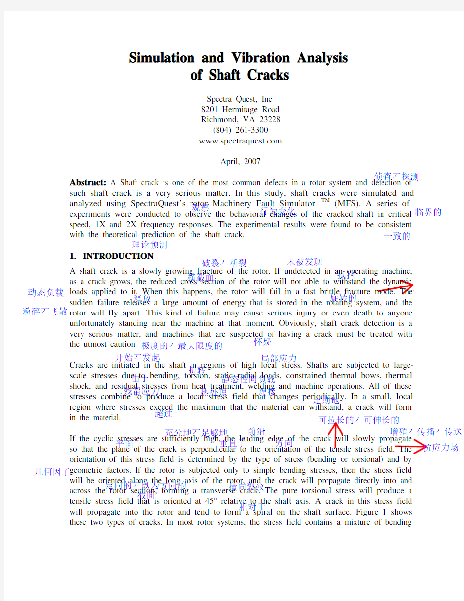
will be oriented along the long axis of the rotor, and the crack will propagate directly into and across the rotor section, forming a transverse crack. The pure torsional stress will produce a tensile stress field that is oriented at 45° relative to the shaft axis. A crack in this stress field will propagate into the rotor and tend to form a spiral on the shaft surface. Figure 1 shows these two types of cracks. In most rotor systems, the stress field contains a mixture of bending
侦查丆探测观察行为变化临界的理论预测一致的破裂丆断裂未被发现横截面抵挡动态负载释放旋转的粉碎丆飞散怀疑极度的丆最大限度的开始丆发起局部应力由于扭转静态径向负载残留应力热处理焊接定期地超过充分地丆足够地前沿增殖丆传播丆传送平面垂直于方向抗应力场可拉长的丆可伸长的几何因子定向的丆以为方向的截面横向裂纹相对于
and torsional stress. Bending stress, however, is usually the dominant component, thus the
crack will usually propagated into the rotor more or less as a transverse crack.
Figure 1. Transverse and torsion cracks.
Shaft bending stiffness is related to the shaft cross-section area. As a crack propagates across
the shaft, the remaining cross section becomes smaller, and the bending stiffness of the shaft decreases. This will reduce the resonance frequency as well as the critical speed of the rotor system. The reduction in shaft stiffness also causes the rotor to bow more in response to a static or dynamic load, such as a rotating unbalance. The bow is likely to change over time. As a result, it will change the effective location and magnitude of the heavy spot, which will consequently change the 1X rotor response.
If a rotor with a crack has a steady, unidirectional radial load, then a strong 2X response may appear when the rotor is turning at half of any resonance speed. As a breathing crack involves both the closing and opening in one revolution, the rotor will respond at the 2X frequency. If a resonance exists at twice running speed, then the 2X vibration will be amplified.
In this study, a series of tests were carried out on a SpectraQuest MFS with cracked shafts to observe their behavioral changes, including the critical speed, 1X and 2X frequency responses, compared with an intact shaft.
2. EXPERIMENTAL SETUP
Three experiments were designed to approach the objective of this study. They were:
A. Cracked shaft simulated using Flange
B. Notched shaft with V-shape crack 1.6” from the inboard bearing housing
C. Notched shaft with V-shape crack 1” from the inboard bearing housing The changes of critical speeds for the intact and cracked shafts were studied in experiments A and B. The changes of 1X and 2X frequency responses for the intact and cracked shafts were 占优势的弯曲进度丆弯曲刚度共振频率弯曲回转运动不平衡随着时间实际位置单向的径向载荷呼吸的 ?C 逼真的旋转振动完整的丆未受损伤的
轴承箱内侧完整的
investigated in experiments B and C. The running speeds were chosen to be 2000 rpm and 4000 rpm.
The tests were conducted on the rotor MFS which is illustrated in Figure 2. Four accelerometers were mounted on the inboard and outboard bearing housings in the vertical and horizontal direction, respectively. The setup of experiment A is shown in Figure 3.
Figure 2 SpectraQuest’s Machinery Fault Simulator (MFS)
Figure 3 shows the flange-simulated cracked shaft. It consists of two separable shafts joined at
the mating flanges. The four (4) bolts compress Belleville washers which can be loosened or tightened in a pattern to create an un-symmetric time varying stiffness and simulate the opening and closing of a transverse crack. The large disc next to the flanges provides gravity
loading and a shaft bending moment. Tests were run with one, two and three bolts loosened.
Figure 3. Setup for experiment A The setup for experiments B and C use a shaft with a simple 90 degree 0.150” deep notch. A small tapped hole in the center allowed a small filler piece to be clamped in the notch to vary the stiffness change due to the notch. Tests were run with the filler piece removed, partially and fully tightened.
研究实施
加速计垂直的水平的
分别地使紧密配合不对称的横向裂纹刻痕螺纹孔加紧改变刚性变化
3.EXPERIMENTAL RESULTS AND ANALYSIS
All experimental data have been collected and analyzed by using SpectraQuest’s VibraQuest software package. Transient, Waterfall and Analysis tools of this software package were mainly used in this study.
3.1 Change of critical speeds
The critical speed in start-up tests can be identified by using time-frequency spectrogram, time waveform, and waterfall plot of the acceleration signals, shown as Figs. 4 through 6
横坐标
respectively. In Fig. 5 the abscissa is time (second). The red spot where a cursor points represents the first critical. The cursor values indicates that the critical occurs at 21.7 second and 65.62 Hz. For Experiment A, the critical speeds for different cracked conditions on the shaft are listed in Table 1, where the “all bolts tight condition” condition simulates no crack
on the shaft, and three-loose means the most seriously cracked condition.
Figure 4. Time waveform of the start-up and cost-down test for “all bolts tight” condition.
Figure 6. Waterfall plot of the start-up and coast-down in the flange-simulated crack test
Table 1 Change of the critical speed in Experiment A
Conditions Critical speed (Hz)
All bolts tight 65.62
One bolt loose 65.00
Two bolts loose 64.37
Three bolts loose 64.37
The critical speeds for different cracked conditions on the shaft in Experiment B are listed in Table 2. Intact means no crack on the shaft and “No-filler” represents the most serious crack condition. Filler fully tightened and Filler partially tightened (more serious than Filler fully tightened) stand for the middle cracked conditions.
Table 2 Change of the critical speed in Experiment B
Critical speed (Hz)
Intact 65.00 Filler fully tightened 62.50
Filler partially tightened 62.50
No-filler 60.00 Both tables have demonstrated that as the crack grows, the critical speed decreases due to the reduced stiffness. The overall trend of these results matches the theory of shaft crack quite well. Figure 7 clearly shows this trend for the changes of critical speeds in different crack conditions.
Figure 7. Changes of critical speeds as the crack conditions change
3.2 1X and 2X frequency response
Using the analysis functions in the VibraQuest software package, as shown in Fig. 8, it is easy to obtain the 1X and 2X frequency response for each steady-state tests in Experiments B and
C. Because the critical speeds of the rotor systems were around 60 Hz to 65 Hz, when the running speed is 2000 rpm (33.33 Hz) in the tests, 2X will be close to the resonance frequency. So both the 1X and 2X components need to be analyzed. When the running speed is 4000 rpm (66.67 Hz), 1X is close to the resonance frequency and 2X will be far away from it. Therefore, only the 1X frequency response has been analyzed.
Figure 8. Frequency analysis of 1X and 2X frequency responses
组件
Table 3. 1X and 2X frequency responses for 2000 rpm in experiment B Experiment B, 2000 rpm
1X (g) 2X (g) Intact shaft
9.578e-3 1.753e-2 Cracked shaft (No-filler)
1.746e-2
2.125e-2
Table 4. 1X frequency responses for 4000 rpm in Experiment B
Experiment B, 4000 rpm
1X (g) Intact shaft
8.732e-2 Cracked shaft (No-filler)
2.756e-1
Table 5. 1X and 2X frequency responses for 2000 rpm in Experiment C Experiment C, 2000 rpm
1X (dg) 2X (g) Intact shaft
9.578e-3 1.753e-2 Cracked shaft (No-filler)
2.729e-2 1.471e-2
Table 6. 1X frequency responses for 4000 rpm in Experiment C
Experiment C, 4000 rpm
1X (g) Intact shaft
8.732e-2 Cracked shaft (No-filler) 1.714e-1
Tables 3 through 6 show the results of 1X and 2X frequency response for all cases of Experiments B and C. Comparing these results shows that normally the 1X and 2X frequency responses of the cracked shaft are larger than that of the intact shaft. This means the crack in the shaft has changed and amplified the 1X and 2X vibration responses. This result is consistent with the theoretical consequence about the shaft crack which has been mentioned before in the introduction.
4. SUMMARY A shaft crack is a slowly growing fatigue fracture of the rotor. Damage of a crack failure can cause serious injury and therefore detection of shaft crack is very important. Shaft crack reduced the bending stiffness of the shaft due to the reduced available cross-section area. That will change the critical speed of the rotor system, and its 1X and 2X frequency response when the system is operated at one-half of a resonance frequency. All these provide the diagnosis for shaft cracks.
In this study, shaft cracks were simulated and analyzed using SpectraQuest rotor Machinery Fault Simulator and the VibraQuest software package. A series of experiments were conducted to observe the behavioral changes of the cracked shaft in critical speed, 1X and 2X frequency responses. The results show that the critical speed decreased as the crack increased, and the 1X and 2X frequency response for cracked shaft increased compared with the intact shaft. Those results are consistent with the theoretical consequence of the shaft crack. 放大疲劳断裂裂纹破坏有效的诊断
毕业论文英文参考文献与译文
Inventory management Inventory Control On the so-called "inventory control", many people will interpret it as a "storage management", which is actually a big distortion. The traditional narrow view, mainly for warehouse inventory control of materials for inventory, data processing, storage, distribution, etc., through the implementation of anti-corrosion, temperature and humidity control means, to make the custody of the physical inventory to maintain optimum purposes. This is just a form of inventory control, or can be defined as the physical inventory control. How, then, from a broad perspective to understand inventory control? Inventory control should be related to the company's financial and operational objectives, in particular operating cash flow by optimizing the entire demand and supply chain management processes (DSCM), a reasonable set of ERP control strategy, and supported by appropriate information processing tools, tools to achieved in ensuring the timely delivery of the premise, as far as possible to reduce inventory levels, reducing inventory and obsolescence, the risk of devaluation. In this sense, the physical inventory control to achieve financial goals is just a means to control the entire inventory or just a necessary part; from the perspective of organizational functions, physical inventory control, warehouse management is mainly the responsibility of The broad inventory control is the demand and supply chain management, and the whole company's responsibility. Why until now many people's understanding of inventory control, limited physical inventory control? The following two reasons can not be ignored: First, our enterprises do not attach importance to inventory control. Especially those who benefit relatively good business, as long as there is money on the few people to consider the problem of inventory turnover. Inventory control is simply interpreted as warehouse management, unless the time to spend money, it may have been to see the inventory problem, and see the results are often very simple procurement to buy more, or did not do warehouse departments . Second, ERP misleading. Invoicing software is simple audacity to call it ERP, companies on their so-called ERP can reduce the number of inventory, inventory control, seems to rely on their small software can get. Even as SAP, BAAN ERP world, the field of
机械专业外文翻译中英文翻译
外文翻译 英文原文 Belt Conveying Systems Development of driving system Among the methods of material conveying employed,belt conveyors play a very important part in the reliable carrying of material over long distances at competitive cost.Conveyor systems have become larger and more complex and drive systems have also been going through a process of evolution and will continue to do so.Nowadays,bigger belts require more power and have brought the need for larger individual drives as well as multiple drives such as 3 drives of 750 kW for one belt(this is the case for the conveyor drives in Chengzhuang Mine).The ability to control drive acceleration torque is critical to belt conveyors’ performance.An efficient drive system should be able to provide smooth,soft starts while maintaining belt tensions within the specified safe limits.For load sharing on multiple drives.torque and speed control are also important consideratio ns in the drive system’s design. Due to the advances in conveyor drive control technology,at present many more reliable.Cost-effective and performance-driven conveyor drive systems cov ering a wide range of power are available for customers’ choices[1]. 1 Analysis on conveyor drive technologies 1.1 Direct drives Full-voltage starters.With a full-voltage starter design,the conveyor head shaft is direct-coupled to the motor through the gear drive.Direct full-voltage starters are adequate for relatively low-power, simple-profile conveyors.With direct fu11-voltage starters.no control is provided for various conveyor loads and.depending on the ratio between fu11- and no-1oad power requirements,empty starting times can be three or four times faster than full load.The maintenance-free starting system is simple,low-cost and very reliable.However, they cannot control starting torque and maximum stall torque;therefore.they are
《机械工程专业英语教程》课文翻译
Lesson 1 力学的基本概念 1、词汇: statics [st?tiks] 静力学;dynamics动力学;constraint约束;magnetic [m?ɡ'netik]有磁性的;external [eks't?:nl] 外面的, 外部的;meshing啮合;follower从动件;magnitude ['m?ɡnitju:d] 大小;intensity强度,应力;non-coincident [k?u'insid?nt]不重合;parallel ['p?r?lel]平行;intuitive 直观的;substance物质;proportional [pr?'p?:??n?l]比例的;resist抵抗,对抗;celestial [si'lestj?l]天空的;product乘积;particle质点;elastic [i'l?stik]弹性;deformed变形的;strain拉力;uniform全都相同的;velocity[vi'l?siti]速度;scalar['skeil?]标量;vector['vekt?]矢量;displacement代替;momentum [m?u'ment?m]动量; 2、词组 make up of由……组成;if not要不,不然;even through即使,纵然; Lesson 2 力和力的作用效果 1、词汇: machine 机器;mechanism机构;movable活动的;given 规定的,给定的,已知的;perform执行;application 施用;produce引起,导致;stress压力;applied施加的;individual单独的;muscular ['m?skjul?]]力臂;gravity[ɡr?vti]重力;stretch伸展,拉紧,延伸;tensile[tensail]拉力;tension张力,拉力;squeeze挤;compressive 有压力的,压缩的;torsional扭转的;torque转矩;twist扭,转动;molecule [m likju:l]分子的;slide滑动; 滑行;slip滑,溜;one another 互相;shear剪切;independently独立地,自立地;beam梁;compress压;revolve (使)旋转;exert [iɡ'z?:t]用力,尽力,运用,发挥,施加;principle原则, 原理,准则,规范;spin使…旋转;screw螺丝钉;thread螺纹; 2、词组 a number of 许多;deal with 涉及,处理;result from由什么引起;prevent from阻止,防止;tends to 朝某个方向;in combination结合;fly apart飞散; 3、译文: 任何机器或机构的研究表明每一种机构都是由许多可动的零件组成。这些零件从规定的运动转变到期望的运动。另一方面,这些机器完成工作。当由施力引起的运动时,机器就开始工作了。所以,力和机器的研究涉及在一个物体上的力和力的作用效果。 力是推力或者拉力。力的作用效果要么是改变物体的形状或者运动,要么阻止其他的力发生改变。每一种
毕业论文外文翻译模版
吉林化工学院理学院 毕业论文外文翻译English Title(Times New Roman ,三号) 学生学号:08810219 学生姓名:袁庚文 专业班级:信息与计算科学0802 指导教师:赵瑛 职称副教授 起止日期:2012.2.27~2012.3.14 吉林化工学院 Jilin Institute of Chemical Technology
1 外文翻译的基本内容 应选择与本课题密切相关的外文文献(学术期刊网上的),译成中文,与原文装订在一起并独立成册。在毕业答辩前,同论文一起上交。译文字数不应少于3000个汉字。 2 书写规范 2.1 外文翻译的正文格式 正文版心设置为:上边距:3.5厘米,下边距:2.5厘米,左边距:3.5厘米,右边距:2厘米,页眉:2.5厘米,页脚:2厘米。 中文部分正文选用模板中的样式所定义的“正文”,每段落首行缩进2字;或者手动设置成每段落首行缩进2字,字体:宋体,字号:小四,行距:多倍行距1.3,间距:前段、后段均为0行。 这部分工作模板中已经自动设置为缺省值。 2.2标题格式 特别注意:各级标题的具体形式可参照外文原文确定。 1.第一级标题(如:第1章绪论)选用模板中的样式所定义的“标题1”,居左;或者手动设置成字体:黑体,居左,字号:三号,1.5倍行距,段后11磅,段前为11磅。 2.第二级标题(如:1.2 摘要与关键词)选用模板中的样式所定义的“标题2”,居左;或者手动设置成字体:黑体,居左,字号:四号,1.5倍行距,段后为0,段前0.5行。 3.第三级标题(如:1.2.1 摘要)选用模板中的样式所定义的“标题3”,居左;或者手动设置成字体:黑体,居左,字号:小四,1.5倍行距,段后为0,段前0.5行。 标题和后面文字之间空一格(半角)。 3 图表及公式等的格式说明 图表、公式、参考文献等的格式详见《吉林化工学院本科学生毕业设计说明书(论文)撰写规范及标准模版》中相关的说明。
英语专业毕业论文翻译类论文
英语专业毕业论文翻译 类论文 Document number:NOCG-YUNOO-BUYTT-UU986-1986UT
毕业论文(设计)Title:The Application of the Iconicity to the Translation of Chinese Poetry 题目:象似性在中国诗歌翻译中的应用 学生姓名孔令霞 学号 BC09150201 指导教师祁晓菲助教 年级 2009级英语本科(翻译方向)二班 专业英语 系别外国语言文学系
黑龙江外国语学院本科生毕业论文(设计)任务书 摘要
索绪尔提出的语言符号任意性,近些年不断受到质疑,来自语言象似性的研究是最大的挑战。语言象似性理论是针对语言任意性理论提出来的,并在不断发展。象似性是当今认知语言学研究中的一个重要课题,是指语言符号的能指与所指之间的自然联系。本文以中国诗歌英译为例,探讨象似性在中国诗歌翻译中的应用,从以下几个部分阐述:(1)象似性的发展;(2)象似性的定义及分类;(3)中国诗歌翻译的标准;(4)象似性在中国诗歌翻译中的应用,主要从以下几个方面论述:声音象似、顺序象似、数量象似、对称象似方面。通过以上几个方面的探究,探讨了中国诗歌翻译中象似性原则的重大作用,在诗歌翻译过程中有助于得到“形神皆似”和“意美、音美、形美”的理想翻译效果。 关键词:象似性;诗歌;翻译
Abstract The arbitrariness theory of language signs proposed by Saussure is severely challenged by the study of language iconicity in recent years. The theory of iconicity is put forward in contrast to that of arbitrariness and has been developing gradually. Iconicity, which is an important subject in the research of cognitive linguistics, refers to a natural resemblance or analogy between the form of a sign and the object or concept. This thesis mainly discusses the application of the iconicity to the translation of Chinese poetry. The paper is better described from the following parts: (1) The development of the iconicity; (2) The definition and classification of the iconicity; (3) The standards of the translation to Chinese poetry; (4) The application of the iconicity to the translation of Chinese poetry, mainly discussed from the following aspects: sound iconicity, order iconicity, quantity iconicity, and symmetrical iconicity. Through in-depth discussion of the above aspects, this paper could come to the conclusion that the iconicity is very important in the translation of poetry. It is conductive to reach the ideal effect of “the similarity of form and spirit” and “the three beauties”. Key words: the iconicity; poetry; translation
机械类英语论文及翻译翻译
High-speed milling High-speed machining is an advanced manufacturing technology, different from the traditional processing methods. The spindle speed, cutting feed rate, cutting a small amount of units within the time of removal of material has increased three to six times. With high efficiency, high precision and high quality surface as the basic characteristics of the automobile industry, aerospace, mold manufacturing and instrumentation industry, such as access to a wide range of applications, has made significant economic benefits, is the contemporary importance of advanced manufacturing technology. For a long time, people die on the processing has been using a grinding or milling EDM (EDM) processing, grinding, polishing methods. Although the high hardness of the EDM machine parts, but the lower the productivity of its application is limited. With the development of high-speed processing technology, used to replace high-speed cutting, grinding and polishing process to die processing has become possible. To shorten the processing cycle, processing and reliable quality assurance, lower processing costs. 1 One of the advantages of high-speed machining High-speed machining as a die-efficient manufacturing, high-quality, low power consumption in an advanced manufacturing technology. In conventional machining in a series of problems has plagued by high-speed machining of the application have been resolved. 1.1 Increase productivity High-speed cutting of the spindle speed, feed rate compared withtraditional machining, in the nature of the leap, the metal removal rate increased 30 percent to 40 percent, cutting force reduced by 30 percent, the cutting tool life increased by 70% . Hardened parts can be processed, a fixture in many parts to be completed rough, semi-finishing and fine, and all other processes, the complex can reach parts of the surface quality requirements, thus increasing the processing productivity and competitiveness of products in the market. 1.2 Improve processing accuracy and surface quality High-speed machines generally have high rigidity and precision, and other characteristics, processing, cutting the depth of small, fast and feed, cutting force low, the workpiece to reduce heat distortion, and high precision machining, surface roughness small. Milling will be no high-speed processing and milling marks the surface so that the parts greatly enhance the quality of the surface. Processing Aluminum when up Ra0.40.6um, pieces of steel processing at up to Ra0.2 ~ 0.4um.
机械工程专业英语 翻译
2、应力和应变 在任何工程结构中独立的部件或构件将承受来自于部件的使用状况或工作的外部环境的外力作用。如果组件就处于平衡状态,由此而来的各种外力将会为零,但尽管如此,它们共同作用部件的载荷易于使部件变形同时在材料里面产生相应的内力。 有很多不同负载可以应用于构件的方式。负荷根据相应时间的不同可分为: (a)静态负荷是一种在相对较短的时间内逐步达到平衡的应用载荷。 (b)持续负载是一种在很长一段时间为一个常数的载荷, 例如结构的重量。这种类型的载荷以相同的方式作为一个静态负荷; 然而,对一些材料与温度和压力的条件下,短时间的载荷和长时间的载荷抵抗失效的能力可能是不同的。 (c)冲击载荷是一种快速载荷(一种能量载荷)。振动通常导致一个冲击载荷, 一般平衡是不能建立的直到通过自然的阻尼力的作用使振动停止的时候。 (d)重复载荷是一种被应用和去除千万次的载荷。 (e)疲劳载荷或交变载荷是一种大小和设计随时间不断变化的载荷。 上面已经提到,作用于物体的外力与在材料里面产生的相应内力平衡。因此,如果一个杆受到一个均匀的拉伸和压缩,也就是说, 一个力,均匀分布于一截面,那么产生的内力也均匀分布并且可以说杆是受到一个均匀的正常应力,应力被定义为 应力==负载 P /压力 A, 因此根据载荷的性质应力是可以压缩或拉伸的,并被度量为牛顿每平方米或它的倍数。 如果一个杆受到轴向载荷,即是应力,那么杆的长度会改变。如果杆的初始长度L和改变量△L已知,产生的应力定义如下: 应力==改变长△L /初始长 L 因此应力是一个测量材料变形和无量纲的物理量 ,即它没有单位;它只是两个相同单位的物理量的比值。 一般来说,在实践中,在荷载作用下材料的延伸是非常小的, 测量的应力以*10-6的形式是方便的, 即微应变, 使用的符号也相应成为ue。 从某种意义上说,拉伸应力与应变被认为是正的。压缩应力与应变被认为是负的。因此负应力使长度减小。 当负载移除时,如果材料回复到初始的,无负载时的尺寸时,我们就说它是具有弹性的。一特定形式的适用于大范围的工程材料至少工程材料受载荷的大部分的弹性, 产生正比于负载的变形。由于载荷正比于载荷所产生的压力并且变形正比于应变, 这也说明,当材料是弹性的时候, 应力与应变成正比。因此胡克定律陈述, 应力正比于应变。 这定律服从于大部分铁合金在特定的范围内, 甚至以其合理的准确性可以假定适用于其他工程材料比如混凝土,木材,非铁合金。 当一个材料是弹性的时候,当载荷消除之后,任何负载所产生的变形可以完全恢复,没有永久的变形。
机械类数控车床外文翻译外文文献英文文献车床.doc
Lathes Lathes are machine tools designed primarily to do turning, facing and boring, Very little turning is done on other types of machine tools, and none can do it with equal facility. Because lathes also can do drilling and reaming, their versatility permits several operations to be done with a single setup of the work piece. Consequently, more lathes of various types are used in manufacturing than any other machine tool. The essential components of a lathe are the bed, headstock assembly, tailstock assembly, and the leads crew and feed rod. The bed is the backbone of a lathe. It usually is made of well normalized or aged gray or nodular cast iron and provides s heavy, rigid frame on which all the other basic components are mounted. Two sets of parallel, longitudinal ways, inner and outer, are contained on the bed, usually on the upper side. Some makers use an inverted V-shape for all four ways, whereas others utilize one inverted V and one flat way in one or both sets, They are precision-machined to assure accuracy of alignment. On most modern lathes the way are surface-hardened to resist wear and abrasion, but precaution should be taken in operating a lathe to assure that the ways are not damaged. Any inaccuracy in them usually means that the accuracy of the entire lathe is destroyed. The headstock is mounted in a foxed position on the inner ways, usually at the left end of the bed. It provides a powered means of rotating the word at various speeds . Essentially, it consists of a hollow spindle, mounted in accurate bearings, and a set of transmission gears-similar to a truck transmission—through which the spindle can be rotated at a number of speeds. Most lathes provide from 8 to 18 speeds, usually in a geometric ratio, and on modern lathes all the speeds can be obtained merely by moving from two to four levers. An increasing trend is to provide a continuously variable speed range through electrical or mechanical drives. Because the accuracy of a lathe is greatly dependent on the spindle, it is of heavy construction and mounted in heavy bearings, usually preloaded tapered roller or ball types. The spindle has a hole extending through its length, through which long bar stock can be fed. The size of maximum size of bar stock that can be machined when the material must be fed through spindle. The tailsticd assembly consists, essentially, of three parts. A lower casting fits on the inner ways of the bed and can slide longitudinally thereon, with a means for clamping the entire assembly in any desired location, An upper casting fits on the lower one and can be moved transversely upon it, on some type of keyed ways, to permit aligning the assembly is the tailstock quill. This is a hollow steel cylinder, usually about 51 to 76mm(2to 3 inches) in diameter, that can be moved several inches longitudinally in and out of the upper casting by means of a hand wheel and screw. The size of a lathe is designated by two dimensions. The first is known as the swing. This is the maximum diameter of work that can be rotated on a lathe. It is approximately twice the distance between the line connecting the lathe centers and the nearest point on the ways, The second size dimension is the maximum distance between centers. The swing thus indicates the maximum work piece diameter that can be turned in the lathe, while the distance between centers indicates the maximum length of work piece that can be mounted between centers. Engine lathes are the type most frequently used in manufacturing. They are heavy-duty machine tools with all the components described previously and have power drive for all tool movements except on the compound rest. They commonly range in size from 305 to 610 mm(12 to 24 inches)swing and from 610 to 1219 mm(24 to 48 inches) center distances, but swings up to 1270 mm(50 inches) and center distances up
大学毕业论文---软件专业外文文献中英文翻译
软件专业毕业论文外文文献中英文翻译 Object landscapes and lifetimes Tech nically, OOP is just about abstract data typing, in herita nee, and polymorphism, but other issues can be at least as importa nt. The rema in der of this sect ion will cover these issues. One of the most importa nt factors is the way objects are created and destroyed. Where is the data for an object and how is the lifetime of the object con trolled? There are differe nt philosophies at work here. C++ takes the approach that con trol of efficie ncy is the most importa nt issue, so it gives the programmer a choice. For maximum run-time speed, the storage and lifetime can be determined while the program is being written, by placing the objects on the stack (these are sometimes called automatic or scoped variables) or in the static storage area. This places a priority on the speed of storage allocatio n and release, and con trol of these can be very valuable in some situati ons. However, you sacrifice flexibility because you must know the exact qua ntity, lifetime, and type of objects while you're writing the program. If you are trying to solve a more general problem such as computer-aided desig n, warehouse man ageme nt, or air-traffic con trol, this is too restrictive. The sec ond approach is to create objects dyn amically in a pool of memory called the heap. In this approach, you don't know un til run-time how many objects you n eed, what their lifetime is, or what their exact type is. Those are determined at the spur of the moment while the program is runnin g. If you n eed a new object, you simply make it on the heap at the point that you n eed it. Because the storage is man aged dyn amically, at run-time, the amount of time required to allocate storage on the heap is sig ni fica ntly Ion ger tha n the time to create storage on the stack. (Creat ing storage on the stack is ofte n a si ngle assembly in structio n to move the stack poin ter dow n, and ano ther to move it back up.) The dyn amic approach makes the gen erally logical assumpti on that objects tend to be complicated, so the extra overhead of finding storage and releas ing that storage will not have an importa nt impact on the creati on of an object .In additi on, the greater flexibility is esse ntial to solve the gen eral program ming problem. Java uses the sec ond approach, exclusive". Every time you want to create an object, you use the new keyword to build a dyn amic in sta nee of that object. There's ano ther issue, however, and that's the lifetime of an object. With Ian guages that allow objects to be created on the stack, the compiler determines how long the object lasts and can automatically destroy it. However, if you create it on the heap the compiler has no kno wledge of its lifetime. In a Ianguage like C++, you must determine programmatically when to destroy the