PTR90说明书
美国PTR工业公司MSG 91狙击步枪

美国PTR工业公司MSG 91狙击步枪
作者:暂无
来源:《轻兵器》 2013年第13期
MSG 91狙击步枪是在HK公司MSG 90狙击步枪基础上改进而成的。
该枪采用长度为457mm 的比赛级枪管,枪管上设有散热槽,枪管口部安装了消焰器,发射7.62mm NATO弹,弹匣容弹量为20发。
战术型护手采用军用特种铝合金经阳极氧化处理而成,下方设有皮卡汀尼导轨,导轨上安装有哈里斯两脚架。
机匣顶部也装有皮卡汀尼导轨,用于安装光学瞄准镜,也可安装照门。
带圆形护翼的准星则固定安装于护手前方。
该枪采用了HK公司海军型聚合物制扳机系统,麦格普公司PRS2枪托,枪托底板和贴腮板可调。
枪托底板缩回时,全枪长1 045mm;枪托底板伸长时,全枪长1 076mm。
全枪质量5.44kg。
GD90使用说明书
GD90 使用说明书承蒙惠顾,至为感谢。
在使用前,请仔细阅读本说明书,如有疑问请与我们联系。
注 意本产品施有防静电措施,对烙铁部分机身作接地,请特别留意下列注意事项:1.手柄等塑胶为有导电性塑胶,修理时请注意。
部件更换或修理时,切勿损伤绝缘材料。
2.请务必接地使用。
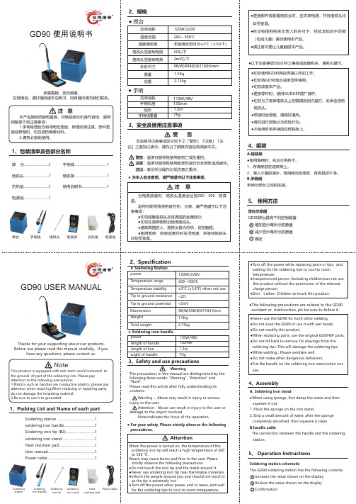
1、包装清单及各部分名称焊 台 (1)烙铁头 (1)抗热垫 (1)电源线........................1 手柄线 (1)烙铁架 (1)使用说明书 (1)● 焊台2、规格功率消耗温度范围温度稳定度烙铁头至接地电阻烙铁头至接地电势外形尺寸重量总重120W/220V200~500℃非使用状态时为±2℃(±3.6℉)2Ω以下2mV以下98(W)X98(D)X118(H)mm1.5Kg2.15kg● 手柄手柄长度 150mm线长 1.3m手柄线重量 75g3、安全及使用注意事项警 告本说明书注意事项区分如下之「警告」「注意」「注记」三者加以表示。
请充分了解其内容后再阅读本文。
●更换部件或装置烙铁头时,应关掉电源,并待烙铁头冷却至室温。
●在没有得到相关负责人的许可下,经验及知识不足者(包括儿童)请勿使用本产品。
●请注意不要让儿童触碰本产品。
●以下注意事项与GD90之事故或故障有关,请务必遵守。
●切勿使用GD90用在焊接以外的工作。
●切勿将GD90泡水或用湿手使用。
●切勿改装本产品。
●更换零件时,使用GUDHEP原厂部件。
●切勿为了弄掉烙铁头上的锡屑而用力敲打。
此举会损伤烙铁头。
●焊接时会冒烟,请做好通风。
●请勿进行其他认为危险行为。
●不使用时将手柄放在焊铁架上。
4、组装A.烙铁架●使用海绵时,先沾水再挤干。
1、将海绵放在烙铁架上。
2、滴入少量的清水,等海绵完全吸收,再将其挤干净。
B.手柄线手柄与焊台之间的连接。
5、 使用方法焊台示意图GD90焊台具有下列控制装置:增加显示幕所示的数值减少显示幕所示的数值确定GD90 USER MANUALThanks for your supporting about our products.Before use please read this manual carefully,If you have any questions, please contact us.NoteThis product is equipped with anti-static and Connected to the ground of part of the soldering iron. Please pay attention to the following precautions:1.Plastics such as handles are conductive plastics, please pay attention when repairing.When replacing or repairing parts, do not damage the insulating material.2.Be sure to use it to grounded.1、Packing List and Name of each part警告:滥用可能导致使用者伤亡或负重伤。
Tempo CableScout TV90 商品说明书

CABLESCOUT TV90CableScout TV90TDR Cable Tester for CA TVA P P L I C A T I O N S:If your job is to find faults on coaxial cable, the Tempo CableScout®TV90 is built for you. Designed specifically for CATVand other coaxial cable applications, the TV90 applies the newest technology to provide both ease of use and coaxialcable testing performance not found in any other TDR.With the TV90, you'll spend less time operating the TDR and more time repairing faults. Simply select the cable type to betested and the TV90 does the rest. Pulse width, VP, gain, and vertical position are automatically selected and adjusted asyou scan the cable. Finding the fault couldn't be faster, just move the cursor to the fault and use the one-button zoomfunction to pinpoint its location.On the performance side, the TV90 employs optimized pulsing and sampling, coupled with advanced filtering andsignal-processing techniques. You always have a clean waveform for easiest event identification.SHORT PULSE WIDTHThe TV90 uses a 6-ns pulse width for close-in resolution. Faults as near as 3 feet from the pedestal are located with ease.RUGGED PACKAGEBest of all, you get all this performance and ease of use in a small, light, rugged TDR package. Come snow, rain, heat, orhumidity, the TV90 keeps working because you have to.F E A T U R E S:•Large, High-Resolution, Backlit Display•Splash, Dust, and Shock-Resistant Packaging•Easy to Use – Anyone Can Use It•One Button Expand/Full-View Function•Dedicated 75 ΩF Connector•Intermittent Fault Location•Context-Sensitive Help (Help Screens Available for AllFunctions)•Small, Portable, Lightweight Package (2.2 pounds)•Accurate (±2 ft. up to 200 feet, 1% beyond)•4000-Foot Fault-Location Capability•Internal Cable Types for Fast, Accurate Testing•Rechargeable battery pack•Determine Length of Cabletel 1.800.642.2155 | tel 1.760.598.8900 | fax 1.760.598.5634 | CableScout ™TV90TDR Cable Tester for CA TVTest Signal Output 1/2 sine.Amplitude (into 75 Ω)6ns pulse: 5 V.12ns pulse: 6 V.Pulse Widths 6 and 12 ns.Output Impedance 75 Ω.Input Protection200 V, DC + peak AC to a maximum of 440 Hz, 30second duration.Display RangesEight automatic display ranges.Gain0 to 63 dB.FilterHigh pass, cutoff frequency 150 kHz, plus averaging.Distance Accuracy 0 to 200 ft: ± 2 ft .Beyond 200 feet: 1% + zero offset.DisplayResolution: 520 x 200 pixels.Size: 5.25 inches.Type: High contrast LCD.Backlight: Operator switchable.Distance Measurements Meters, feet, nanoseconds.Auto Shutoff Time Operator selectable:5 to 30 minutes.Disabled.Characteristics©2004 Tempo ML-0054, 8/04, 2.5M Subject to change without noticeCABLESCOUT TV90。
软声音软声 VS90 产品说明书

C9MPVSoftSound™VS90Product Specifications90+Variable SpeedTwo--Stage Heating FurnaceFLEXIBILITY•Supports two--stage cooling units•Dual Certified venting(1or2pipe),Direct Vent Furnace•40″(1016mm)high with wider cabinets,for ease of installation•Factory shipped for natural gas,with PropaneGas conversion kits available•Four position--upflow/downflow/horizontal installation•Vent pipe can be run horizontally or vertically•Internal condensate drain systemSERVICE•Self diagnostics•Entire blower assembly removableCOMFORT•Adjustable timed blower heating Off delay •Adjustable timed blower cooling On/Off delay •Thermal lined,one piece steel cabinet for noise reduction •Insulated blower compartment•24and115VAC humidifier terminals•Electronic air cleaner terminal•Dehumidification optionEFFICIENCY•92.1%AFUE•Two--stage operation•ECM Variable speed DC motor•Two--stage Induced draft blower•In--shot burnersQUALITY•RPJ III Stainless steel heat exchanger•Stainless steel secondary heat exchanger•High temperature limit control prevents overheating •Direct ignition with Silicon Nitride igniton•Flame roll--out sensors standard•External filter rack with permanent filters•Solid doorsWARRANTY*•10year No Hassle Replacement t limited warranty •Lifetime heat exchanger limited warranty with timely registration•5year parts limited warranty--With timely registration,an additional5year parts limited warranty*Applies to original purchaser/homeowner,some limitations may apply.See warranty certificate for complete details.Illustrations and photographs areonly representative.Some product models may vary.THIS MODEL92.1As an Energy Star®Partner,International Comfort Productshas determined that this productmeets the ENERGY STAR®guidelines for energy efficiency.Ask your contractor for details orvisit UPFLOW/DOWNFLOW/HORIZONTAL(NATURAL GAS)Model NumberDimensions H x W x D Input(MBTUH)EfficiencyAFUECooling Capacity@.5in wc(125Pa)Shipping Wt. Inches Millimeters Lbs KgC9MPV050F12D40x191/8x291016x486x7375092.1 1.5--3.0TON15068 C9MPV075F12D40x191/8x291016x486x7377592.1 1.5--3.5TON16876 C9MPV100J20D40x223/4x291016x578x73710092.13--5.0TON18785 C9MPV125L20D40x241/2x291016x522x73712592.13--5.0TON20392Model Number*Denotes Brand(C,H,T)*9MPV050F12*9MPV075F12*9MPV100J20*9MPV125L20INPUT HIGH HEAT(BTUH)LOW HEAT(BTUH)50,00035,00075,00052,500100,00070,000125,00087,500HTG.CAP.HIGH HEAT(BTUH)LOW HEAT(BTUH)46,00032,00070,00048,00093,00065,000118,00082,000AFUE%(ICS)92.192.192.192.1TEMP.RISE RANGE High Heat(o F/o C)Low Heat(o F/o C)35--65/19--3635--65/19--3640--70/22--3940--70/22--3940--70/22--3940--70/22--3940--70/22--3940--70/22--39VENT SIZE^--in(mm)2″(50.8)OD2″--3″(50.8or76.2)OD3″(76.2)OD3″(76.2)OD VOLTS/HZ/PH115/60/1115/60/1115/60/1115/60/1 RATING PLATE AMPS.9.511.414.615.4MIN./MAX.VOLTAGE104/127104/127104/127104/127 TRANSFORMER(V.A.)40404040GAS PIPE SIZE--in(mm)1/2(12.7)1/2(12.7)1/2(12.7)1/2(12.7) COOLING CAP.(TONS) 3.0 3.0 5.0 5.0HIGH ALTITUDE PRESSURE SWITCH1013165101316510131651013157 FILTER SIZE--in(mm)16X25X1(406x635x25)(1)16X25X1(406x635x25)(1)16X25X1(406x635x25)(2)16X25X1(406x635x25)(2)DIMENSIONS W x D x H--in(mm)191/8x29x40(486x737x1016)191/8x29x40(486x737x1016)223/4x29x40(486x737x1016)241/2x29x40(622x737x1016)WEIGHT--Lbs.(Kg)150(68)168(76)187(85)203(92) ^Vent size may vary depending on length,number of elbows,standard vent or direct vent.See Installation Instructions.Brand Identifier Engineering Rev. *=Brand Denotes minor changesMarketing Digit Model Efficiency Denotes major change 8=Non--Condensing,80+%Gas Furnace Cooling Airflow 9=Condensing,90+%Gas Furnace08=800CFM12=1200CFM Installation Configuration14=1400CFM UP=Upflow DN=Downflow UH=Upflow/Horizontal16=1600CFM HZ=Horizontal DH=Downflow/Horizontal20=2000CFM MP=Multiposition,Up/Down/Horizontal Cabinet Width Major Design Feature B=15.5″Wide 1=One(Single)Pipe N=Single Stage F=19.1″Wide 2=Two Pipe P=PVC Vent J=22.8″Wide D=1or2Pipe T=Two Stage L=24.5″Wide L=Low NOx V=Variable Speed Input(Nominal MBTUH) *Denotes Brand(C,H,T)Model Number Description Used With ModelsNAHA002NG 1172961**Gas Conversion Kits(2--Stage)--Propane to natural gas conversion kit.Allows field conversion to natural gas.*9MPVNAHA002LP 1172959**Gas Conversion Kits(2--Stage)--Natural gas to Propane conversion Kit(includes low pressure switch).Allows field conversion to Propane gas.*9MPVNAHA001FF Filter Kits--External filter frame.16″x25″(406mm x635mm)Side Return(All Furnaces)Bottom Return(All“F”191/8″Furnaces under1600CFM)NAHA001FP External filter frame.16″x25″(406mm x635mm)Bulk Pack Kit--Qty10NAHA002FF Filter Kits--Bottom return filter frame kit20″x25″(All“J”223/4″Furnaces)NAHA002FP Bottom return filter frame kit20″x25″(508mm x635mm)Bulk Pack Kit--Qty10NAHA001TK Duct Standoff Filter Kit--To adapt20″x25″(508mm x635mm)filter for single side return.Side Return(All single return applications with1600CFM or greater)Bottom Return(All“F”191/8″Furnaces under1600CFM)NAHA001NK612833**Condensate Neutralizer Kit--for condensing gas furnaces All*9MPV Furnaces if RequiredNAHH002SB Combustible Floor Subbase--Subbase Furnace ONLY:All191/4″widefurnace models*9MPV050/075NAHH003SB Combustible Floor Subbase--Subbase Furnace ONLY:All223/4″widefurnace models*9MPV100NAHH010SB Combustible Floor Subbase--Subbase Furnace ONLY:All241/2″widefurnace models*9MPV125NAHH005SB Subbase--Furnace w/191/4″cased coil*9MPV050/075Counterflow furnace w/191/4″cased coil NAHH006SB Subbase--Furnace w/223/4″cased coil*9MPV100Counterflow furnace w/223/4″cased coil NAHH009SB Subbase Furnace w/241/2″cased coil*9MPV125Counterflow furnace w/241/2″cased coil 1013165**High Altitude Pressure Switch Kit*9MPV050,075&100 1013157**High Altitude Pressure Switch Kit*9MPV125NAHA001CV 1011129**3″(76.2mm)Concentric Vent Kit--allows single wall penetration for2pipe direct vent applications(90+).*9MPV100/125NAHA002CV2″(50.8mm)Concentric Vent Kit--allows single wall penetration for2pipe direct vent applications(90+).*9MPV050/075 NAHA001CA Coil Adapter for Downflow FurnacesNAHA002WL To replace Warning Labels,Operating Instructions&Wiring Labels onBlower Door when needed*9MPV*Denotes Brand(C,H,T)**Fast part numberCooling Adjustment Heating Rise AdjustmentDIP Switch (OFF=0ON=1)High Cool@.50in wc(125Pa)Low Cool(80%of High Cool)**AdjustJumperSettingDIP Switch(OFF=0ON=1)High HeatRiseChange@0.20in wc(50Pa)Low HeatRiseChange atResultantStatic5&6CFM L/s CFM L/s3&4001246588997471+00--4--3 *001211571969457*NOM*0000 001122529898424--0055 011105521884417+0134 011027485822388NOM0177 01945446756357--011314 10892421714337+10--10 10820387656310NOM1045 10745352596281--1099 11688325550260+11--15--15 11609287487230NOM11--13--12 11541255433204--11--9--9 Airflow performance includes1”washable filter media.*Factory Setting**Adjust Jumper Setting(+,NOM,--)is applied to both Cooling and HeatingNote1:HP Mode Jumper provides a10%reduction in airflow when in Comfort position and a call for low or high cooling is present with the”O”line off.This feature is to provide lower airflow for running in HP Heating Mode if desirable.Note2:DEHUM mode(24VAC on DEHUM terminal)provides a20%airflow reduction during cooling calls.Note3:Low Heat ESP is a result of High Heat ESP(--is decrease in rise).Note4:High and low heat rise values are approximate air temperature change from return air temperature when at factory default settings.Table2AirflowDIP Switch (OFF=0/ON=1)Continuous Fan@ 0.10in wc(25Pa)ESP1&2CFM L/s*00592279011021482101346635111346635 *Factory SettingTable3SW2DIP Assignments DIP Switch Blower Parameter 1&2Cont Fan Adj3&4Heat Speed Adj5&6Cool Speed Adj7&8Cool On/Off DelayTable4Cooling Delay Options(SW2--7,8)ON DELAY OFF DELAYDIP SW2--7/8 (OFF=0/ON=1)Timed ON(sec)Airflow during ondelay Timer OFF(sec)Airflow during offdelay*005OFF90100% 015OFF0OFF103050%30100% 113050%18050% Airflow%is of High Cool airflow demand determined from SW2--5/6Table1Airflow resumes to100%after on delay time is completedAirflow stops(or switches to continuous fan speed)after off delay time is completed*Factory SettingMAX CFM(L/s)for Factory Washable Filters Filter Size(in/mm)CFM L/s14″X25″(356x635)140066116″X25″(406x635)160075520″X25″(508x635)200094424″X25″(610x635)25001180Max CFM(L/s)based on600FPM(3.0M/s)NOTE:Disposable filters are typically rated at300FPM(1.5M/s). These filters only allow half the airflow when compared to600FPM (3.0M/s)filters.EXAMPLE(approx.):20in X25in@600FPM=2000CFM,@300FPM=1000CFM 508mm x635mm@3.0M/s=944L/s,@1.5M/s=472L/sCooling Airflow SettingsNOTE:Cooling Adjustment Heating Rise AdjustmentDIP Switch (OFF=0ON=1)High Cool@.50in wc(125Pa)Low Cool(80%of High Cool)**AdjustJumperSettingDIP Switch(OFF=0ON=1)High HeatRiseChange@0.20in wc(50Pa)Low HeatRiseChange atResultantStatic5&6CFM L/s CFM L/s3&40013426331074507+00--4--4 *001210571968457*NOM*0000 001053497842397--0054 011135536908429+0111 011020481816385NOM0165 01872412698329--011210 10965455772364+10--1--1 10840396672317NOM1033 10680321544256--1098 11708334566267+11--6--6 11590278472223NOM11--2--3 11488230390184--1132 Airflow performance includes1”washable filter media.*Factory Setting**Adjust Jumper Setting(+,NOM,--)is applied to both Cooling and HeatingNote1:HP Mode Jumper provides a10%reduction in airflow when in Comfort position and a call for low or high cooling is present with the”O”line off.This feature is to provide lower airflow for running in HP Heating Mode if desirable.Note2:DEHUM mode(24VAC on DEHUM terminal)provides a20%airflow reduction during cooling calls.Note3:Low Heat ESP is a result of High Heat ESP(--is decrease in rise).Note4:High and low heat rise values are approximate air temperature change from return air temperature when at factory default settings.Table2AirflowDIP Switch (OFF=0/ON=1)Continuous Fan@ 0.10in wc(25Pa)ESP1&2CFM L/s*00612289011096517101403662111403662 *Factory SettingTable3SW2DIP Assignments DIP Switch Blower Parameter 1&2Cont Fan Adj3&4Heat Speed Adj5&6Cool Speed Adj7&8Cool On/Off DelayTable4Cooling Delay Options(SW2--7,8)ON DELAY OFF DELAYDIP SW2--7/8 (OFF=0/ON=1)Timed ON(sec)Airflow during ondelay Timer OFF(sec)Airflow during offdelay*005OFF90100% 015OFF0OFF103050%30100% 113050%18050% Airflow%is of High Cool airflow demand determined from SW2--5/6Table1Airflow resumes to100%after on delay time is completedAirflow stops(or switches to continuous fan speed)after off delay time is completed*Factory SettingMAX CFM(L/s)for Factory Washable Filters Filter Size(in/mm)CFM L/s14″X25″(356x635)140066116″X25″(406x635)160075520″X25″(508x635)200094424″X25″(610x635)25001180Max CFM(L/s)based on600FPM(3.0M/s)NOTE:Disposable filters are typically rated at300FPM(1.5M/s). These filters only allow half the airflow when compared to600FPM (3.0M/s)filters.EXAMPLE(approx.):20in X25in@600FPM=2000CFM,@300FPM=1000CFM 508mm x635mm@3.0M/s=944L/s,@1.5M/s=472L/sCooling Airflow SettingsNOTE:Cooling Adjustment Heating Rise AdjustmentDIP Switch (OFF=0ON=1)High Cool@.50in wc(125Pa)Low Cool(80%of High Cool)**AdjustJumperSettingDIP Switch(OFF=0ON=1)High HeatRiseChange@0.20in wc(50Pa)Low HeatRiseChange atResultantStatic5&6CFM L/s CFM L/s3&400214410121715809+00--4--4 *0020139501610760*NOM*0000 0018428691474696--0055 0117728361418669+0121 0116247661299613NOM0187 0114716941177555--011414 1013676451094516+100--1 101227579982463NOM1065 101077508862407--101311 11930439744351+11--6--7 11808380646305NOM11--2--2 11634299507239--1133 Airflow performance includes1”washable filter media.*Factory Setting**Adjust Jumper Setting(+,NOM,--)is applied to both Cooling and HeatingNote1:HP Mode Jumper provides a10%reduction in airflow when in Comfort position and a call for low or high cooling is present with the”O”line off.This feature is to provide lower airflow for running in HP Heating Mode if desirable.Note2:DEHUM mode(24VAC on DEHUM terminal)provides a20%airflow reduction during cooling calls.Note3:Low Heat ESP is a result of High Heat ESP(--is decrease in rise).Note4:High and low heat rise values are approximate air temperature change from return air temperature when at factory default settings.Table2AirflowDIP Switch (OFF=0/ON=1)Continuous Fan@ 0.10in wc(25Pa)ESP1&2CFM L/s*00100747501174282210220410401122041040 *Factory SettingTable3SW2DIP Assignments DIP Switch Blower Parameter 1&2Cont Fan Adj3&4Heat Speed Adj5&6Cool Speed Adj7&8Cool On/Off DelayTable4Cooling Delay Options(SW2--7,8)ON DELAY OFF DELAYDIP SW2--7/8 (OFF=0/ON=1)Timed ON(sec)Airflow during ondelay Timer OFF(sec)Airflow during offdelay*005OFF90100% 015OFF0OFF103050%30100% 113050%18050% Airflow%is of High Cool airflow demand determined from SW2--5/6Table1Airflow resumes to100%after on delay time is completedAirflow stops(or switches to continuous fan speed)after off delay time is completed*Factory SettingMAX CFM(L/s)for Factory Washable Filters Filter Size(in/mm)CFM L/s14″X25″(356x635)140066116″X25″(406x635)160075520″X25″(508x635)200094424″X25″(610x635)25001180Max CFM(L/s)based on600FPM(3.0M/s)NOTE:Disposable filters are typically rated at300FPM(1.5M/s). These filters only allow half the airflow when compared to600FPM (3.0M/s)filters.EXAMPLE(approx.):20in X25in@600FPM=2000CFM,@300FPM=1000CFM 508mm x635mm@3.0M/s=944L/s,@1.5M/s=472L/sCooling Airflow SettingsNOTE:Cooling Adjustment Heating Rise AdjustmentDIP Switch (OFF=0ON=1)High Cool@.50in wc(125Pa)Low Cool(80%of High Cool)**AdjustJumperSettingDIP Switch(OFF=0ON=1)High HeatRiseChange@0.20in wc(50Pa)Low HeatRiseChange atResultantStatic5&6CFM L/s CFM L/s3&400215010151720812+00--4--4 *0020259561620764*NOM*0000 0018568761485700--0045 0117558281404663+0112 0116157621292610NOM0167 0114526851162548--011213 1013386311070505+10--10 101201567961454NOM1034 101069504855403--10910 11909429727343+11--6--6 11800377640302NOM11--3--3 11627296502237--1133 Airflow performance includes1”washable filter media.*Factory Setting**Adjust Jumper Setting(+,NOM,--)is applied to both Cooling and HeatingNote1:HP Mode Jumper provides a10%reduction in airflow when in Comfort position and a call for low or high cooling is present with the”O”line off.This feature is to provide lower airflow for running in HP Heating Mode if desirable.Note2:DEHUM mode(24VAC on DEHUM terminal)provides a20%airflow reduction during cooling calls.Note3:Low Heat ESP is a result of High Heat ESP(--is decrease in rise).Note4:High and low heat rise values are approximate air temperature change from return air temperature when at factory default settings.Table2AirflowDIP Switch (OFF=0/ON=1)Continuous Fan@ 0.10in wc(25Pa)ESP1&2CFM L/s*00103248701177883910217810281121781028 *Factory SettingTable3SW2DIP Assignments DIP Switch Blower Parameter 1&2Cont Fan Adj3&4Heat Speed Adj5&6Cool Speed Adj7&8Cool On/Off DelayTable4Cooling Delay Options(SW2--7,8)ON DELAY OFF DELAYDIP SW2--7/8 (OFF=0/ON=1)Timed ON(sec)Airflow during ondelay Timer OFF(sec)Airflow during offdelay*005OFF90100% 015OFF0OFF103050%30100% 113050%18050% Airflow%is of High Cool airflow demand determined from SW2--5/6Table1Airflow resumes to100%after on delay time is completedAirflow stops(or switches to continuous fan speed)after off delay time is completed*Factory SettingMAX CFM(L/s)for Factory Washable Fil-tersFilter Size(in/mm)CFM L/s14″X25″(356x635)140066116″X25″(406x635)160075520″X25″(508x635)200094424″X25″(610x635)25001180Max CFM(L/s)based on600FPM(3.0M/s)NOTE:Disposable filters are typically rated at300FPM(1.5M/s). These filters only allow half the airflow when compared to600FPM (3.0M/s)filters.EXAMPLE(approx.):20in X25in@600FPM=2000CFM,@300FPM=1000CFM 508mm x635mm@3.0M/s=944L/s,@1.5M/s=472L/sCirculation Air Blower Data-*9MPV125Cooling Airflow SettingSpecifications subject to change without notice.4405620230311I nternational Comfort Products,LLCLewisburg,TN37091U.S.A.Specifications subject to change without notice.4405620230312。
ST-90 Occupancy Counting Switch 产品说明书

12345ITEM DESCRIPTION 1Switch assembly 2Switch body 3Switch cover frame4Screw (2)5Switch cover plate 6Transmitter assembly7Transmitter cable, RJ-11 4P , 157 in. (4m) 8Transmitter moduleITEM DESCRIPTION9Receiver assembly 10Receiver cable,RJ-12 6P , 39 in. (1m) 11Receiver module4MR8PRODUCT OVERVIEWThe SUN9 Occupancy Counting Switch™ is an energy-saving device which reduces energy consumption by automatically controlling lights and ventilation fans based on the counted number of occupants in restrooms or other multi-purpose rooms where occupants enter and exit frequently.The Sun9™ Occupancy Counting Switch™ utilizes a 32-bit microprocessor combined with sensors installed in the doorway of a room to count occupants entering the room and turning on the lamp and ventilation fan accordingly. When all occupants exit the room, connected lamps and fans automatically turn off. The switch can be programmed with time delay to delay the power shut off to either or both circuits when occupancy count is zero (0). An auto shut-off feature allows the unit to work as a motion sensor device whereby the power is shut off after a period of no activity. Each circuit’s time delay can be programmed individually.ELECTRICAL RATINgSPrimaryRelaySecondary RelaySupply Input 120 VAC, 60Hz, 8.8 A (1.1kW)Load Rating 5 A, 600 W,120 VAC Tungsten5 A, 600 W, 120 VAC Fluorescent 1/8 hp (93W), 120 VAC MotorWireDesignationLoad: Red Load: Yellow Connect to Copper Conductors Only, maximum 12 AWG rated maximum 75˚C Class 2 SensorWiring(included)Transmitter, RJ-11 4P - 157 in. (4m)Receiver cable, RJ-12 6P - 39 in. (1m)OperatingEnvironment 77° F/25° C Type 1 Enclosure Should this product be installed to control fluorescent lighting, use newer digital ballasts for longer bulb life.Fan Time Delay procedureB +C +D for 20 seconds A /B C +D for 10 secondsPress B , C and D simultaneously for20 seconds. Fan-Time-Delay mode is entered after 1 second low audible tone and FAN LED flashing.Press A or B to control time. The initial 1 second tone frequency indicates the currently programmed time (see chart).Press C and D simultaneously for 10 seconds to save configuration.Lamp No Activity Shut-Off procedureA +B +C for 20 seconds C /D A +B for 10 secondsPress A , B and C simultaneously for 20 seconds. Lamp-No-Activity-Shut-Off mode is entered after 1 second low audible tone and LAMP LED flashing. Press C or D to control time. The initial 1 second tone frequency indicates the currently programmed time (see chart).Press A and B simultaneously for 10 seconds to save configuration.Fan No Activity Shut-Off procedureA +C +D for 20 seconds A /B ••••••C +D for 10 seconds Press ACand D20 seconds. Fan-No-Activity-Shut-Off mode is entered after 1 second lowaudible tone and FAN LED flashing.Press Aor B1 second tone frequency indicates the currently programmed time (see chart).Press C and D seconds to save configuration.SENSITIVITY CONTROLIf you find that the switch is double-counting, follow these procedures to adjust the sensitivity of the system:B +C for 30 seconds A to adjustB +C for 10 secondsPress B and C simultaneously for 30 seconds. Sensitivity Adjustment mode is entered after 1 second tone.Press A 1 beep 0.01 sec (most sensitive)2 beeps 0.2 seconds 3 beeps 0.4 seconds4 beeps 0.6 sec. (default)5 beeps 0.8 seconds6 beeps 1.0 seconds7 beeps 1.4 seconds (cycles to 1 beep after this)Press B and C seconds to save configuration.MUTINg THE BEEPThe Sun9 Occupancy Counting Switch beeps when it senses an entry or exit. To mute the switch so the beep does not sound, follow these procedures:A +D for 30 seconds•••••--------•B to adjustA +D for 10 seconds Press Aand Dsimultaneously for 30 seconds. Mute mode is entered after 1second tone.Press Bto adjust mute:1 beep MUTE 5 beeps ONPress A and D simultaneously for 10 seconds to save configuration.LIMITED 3-YEAR WARRANTYREgISTER ONLINE:Sun9 offers a LIMITED 3-YEAR WARRANTY to the original owner that all parts and assemblies will be free from defects in material and workmanship. PRODUCT MUST BE INSTALLED BY A LICENSED ELECTRICIAN FOR WARRANTY TO BE VALID . Should any defects develop, Sun9 will, at its discretion and with proof of purchase, repair or replace the item, provided the item has not been abused, misused, altered or damaged after purchase (this includes damage due to use of tools or harsh chemicals).Register your product with Sun9. Register online at , or mail owner’s name and address, copy of original sales receipt, licensed electrician’s name and license number along with installation date to:Sun9, Inc.3540 Wilshire Blvd. Suite 1211 Los Angeles, CA 90010Contact Customer Service for warranty questions or replacement at 213 232 0150.••--•The sensors should be installed in the door jamb 25 to 27 inches from the ground (64 to 69 cm). The sensors should also be installed less than 78 inches apart (200 cm).receiver line64 - 69 cm200 cmmodel and accessories are correct as well as incoming line voltage. ENSURE POWER IS ON and that the circuits are in proper working order before proceeding.The Sun9™ Occupancy Counting Switch™ includes two buttons to manually turn the lamps and fan on and off. By pressing on the top or bottom of each switch, different programming actions are performed.A Top of the Lamp Switch Button BBottom of the Lamp Switch ButtonC Top of the Fan Switch ButtonD Bottom of the Fan Switch ButtonPROgRAMMINgThe Sun9™ Occupancy Counting Switch™ can be programmed to turn off lamps and fan instantly when the last person leaves (factory default), or to delay automatic shut-off by up to 4 hours.The Sun9™ Occupancy Counting Switch™ also includes a “no activity” shut-off feature. This feature is similar to the functionality of a standard motion sensor device, which turns the system off after the programmed time of no activity. Time Delay Programming mode is entered by pressing on three areas at the same time. Specific instructions are included in each time delay programming section.The Time Delay feature allows the lamp to stay on for a programmable amount of time after the last occupant leaves .entered after 1 second low audible tone with the LAMP LED flashing.Press C or D 1 second tone frequency indicates the currently programmed time (see chart).Press A and B seconds to save configuration.••sensor on either side of the doorjamb 25 to 27 inches (64 to 69 cm) from the floor.Mark the horizontal position of eachsensor at least 3/4-inch (19 mm) from the front of the jamb.Ensure each guide is the same distancefrom the floor and equal distance from the front of the door jamb.4.5.。
Parker Hannifin PRN系列旋转轴动作器说明书

ContentsOverview............................................................................28Specifications, Miniature ...................................................29Specifications, Standard ...................................................30Ordering Information .........................................................31Accessories .......................................................................31PRN SeriesVane Rotary ActuatorsPRN SeriesOverviewA074Unique DesignSuitable for non-lubricated air service, Schrader Bellows PRN Series rotary actuatorsincorporate a single or double vane which is molded directly onto a one-piece shaft.The unique rounded vane design assures minimal leakage and allows stable low speedoscillation at low operating pressure while providing long service life.Wide Range of Operating Angles and Start PointsStandard models, which include an optional switch, are available with starting refer-ence points of 40°, 45° and 90° and rotation angles of 90°, 100°, 180°, 270° and280°. Other models are available for manual adjustment of the oscillation angles.The PRN Series also yields a high output torque/weight ratio. For example, thesmallest model, PRN1, weighs only 0.08 pounds and provides 1.40 in-lb torque at100 PSI. The largest model, PRN800D, weighs 27 pounds and provides up to 3,562in-lb torque at 145 PSI.An Ideal SolutionBecause Schrader Bellows rotary actuators are compact and lightweight, they are theperfect choice for a large variety of applications. Accessories and options include theintegral end of stroke hydraulic shock (hydro-cushion), foot and flange mountings, andreed and Hall Effect switches.For complete information, request Catalog 1830-1/USA.Model No.PRN1S PRN3S PRN10S PRN20S PRN30S Rotation Angle (°)9018090180901802709018090180270 Oscillating Reference Point (°)9045, 9045, 904545, 9045Port Size M5M5M5M5Rc1/8Minimum Working Pressure (psi)2121141414Operation Pressure Range (psi)43-10043-10028-10028-14028-140Internal Volume (in3)0.30.60.1460.1580.3050.5180.6020.730.97 2.26 2.26 2.62 Radial Load Capacity (lbs) 2.28.8116688Thrust Load Capacity (lbs)0.220.880.88 5.5 6.6Kinetic Energy Capacity (in-lb)0.00.010.020.130.22 Weight (lbs)0.080.080.150.150.350.350.300.800.80 1.0 1.0 1.0Miniature Double Vane (Size 30)Model No.PRN30DRotation Angle (°)90Oscillating Reference Point (°)45Port Size Rc1/8Minimum Working Pressure (psi)14Internal Volume (in3) 2.05Radial Load Capacity (lbs)88Thrust Load Capacity (lbs) 6.6Kinetic Energy Capacity (in-lb)0.22Weight (lbs) 1.1Torque Output (in-lb) – Miniature ModelsModel Supply Pressure, PSIType Number3045607590100120135 PRN1S—0.500.700.95 1.10 1.33——PRN3S— 1.30 1.90 2.40 3.10 3.52——Single Vane PRN10S 1.95 3.90 5.907.809.9011.33——PRN20S 3.50 6.910.413.916.919.823.430.4PRN30S 6.914.720.827.834.738.948.661.6Double Vane PRN30D23.234.851.666.281.791.7111.8142.7Model No.PRN50S PRN150SRotation Angle (°)9018027028090180270280 Oscillating Reference Point (°)4545,4045404545,404540 Port Size Rc1/8Rc1/4Minimum Working Pressure (psi)1411Operation Pressure Range (psi)28-14040-140Internal Volume (in3) 3.1 3.1 3.72 3.788.908.908.9010.9 Radial Load Capacity (lbs)132264Thrust Load Capacity (lbs)1020Kinetic Energy Capacity (in-lb)0.43 1.98Weight (lbs) 1.80 1.74 1.61 1.54 4.4 4.2 3.74 3.52Standard Double Vane (Sizes 50-800)Model No.PRN50D PRN150D PRN300D PRN800D Rotation Angle (°)90100901009010090100 Oscillating Reference Point (°)45,404045,404045,404045,4040 Port Size Rc1/8Rc1/4Rc3/8Rc1/2 Minimum Working Pressure (psi)1111117 Operation Pressure Range (psi)40-14040-14040-14040-140 Internal Volume (in3) 2.56 2.627.757.5014.8816.5245.446.6 Radial Load Capacity (lbs)1321324401100 Thrust Load Capacity (lbs)101033110 Kinetic Energy Capacity (in-lb)0.43 1.989.534.5 Weight (lbs) 1.8 1.7 4.4 4.29.59.127.927.5Torque Output (in-lb) – Standard ModelsModel Supply Pressure, PSIType Number3045607590100120135 PRN50S10.822.632.141.751.257.872.092.0Single Vane PRN150S47.373.099.0129.0155.0172.4206.0262.0 PRN300S90142194245297331.4396495 PRN800S3255086978801060117814281766 PRN50D28.650.372.090.3111.0124.8152.0195.0Double Vane PRN150D107.5163.0232.0301.0357.0393.3473.0495.0 PRN300D2193354645957147949461178 PRN800D6661028138517672120235528563529Model No.PRN300S PRN800SRotation Angle (°)9018027028090180270280 Oscillating Reference Point (°)4545,4045404545,404540 Port Size Rc3/8Rc1/2Minimum Working Pressure (psi)117Operation Pressure Range (psi)40-14040-140Internal Volume (in3)14.8817.2621.4622.2645.452.3562.463.0 Radial Load Capacity (lbs)4401100Thrust Load Capacity (lbs)33110Kinetic Energy Capacity (in-lb)9.5034.5Weight (lbs)8.28.28.28.027.926.826.824.6PRN SeriesA074Ordering InformationAccessoriesDescription PRN1PRN3PRN10PRN20PRN30PRN50PRN150PRN300PRN800Foot Mounting ✓✓✓✓✓✓✓✓✓Flange Mounting ✓✓✓✓✓✓✓Hall Effect Switches ✓✓✓✓Reed Switches✓✓✓✓Hydraulic Shock Absorber (Hydro-cushion)✓✓✓✓For complete information, request Catalog 1830-1/USA.Ordering InformationPRN SeriesNotes。
发那科数控系统信号跟踪功能的设置及使用
设备管理与维修2021翼6(上)发那科数控系统信号跟踪功能的设置及使用张健,彭飞(西安航天动力研究所,陕西西安710100)摘要:以数控机床普遍使用的FANUC 0i-D 系统为例介绍了系统中信号跟踪功能的设置方法,以及在维修偶发性故障中的使用技巧,为数控设备维修人员提供了有效的方法。
关键词:信号跟踪;偶发故障;PMC 设定;维修案例中图分类号:TG659文献标识码:BDOI :10.16621/ki.issn1001-0599.2021.06.250引言数控系统报警故障根据报警类型分为数控系统报警、伺服报警和PMC 报警3种,其中PMC 报警是最常出现的报警类型。
从报警的特点分为固定报警和偶发性报警。
对于固定出现的报警,可根据报警号和PMC 控制逻辑分析进行故障排查,相对偶发性报警容易处理一些。
而对于偶发性出现的PMC 报警,其特点为报警无规律、可自行恢复、用肉眼观察不到快速闪烁的报警信号等特点,致使故障排查时间很长。
FANUC 数控系统信号跟踪功能是一种专用于FANUC 数控系统中分析信号变化、跟踪信号状态的一种工具,在设备出现PMC 偶发性故障时,靠常规检查手段无法准确、及时判断故障点,信号跟踪功能可以对设备外围输入、输出信号及内部信号的状态变化及时间进行直观的显示,准确捕捉住信号变化的时间点及各信号状态,结合PMC 程序对各种信号之间的逻辑关系进行分析,以便准确判断设备故障点。
1信号跟踪功能的进入要使用跟踪功能,首先需要进入跟踪画面,设定跟踪参数。
按下操作面板上SYSTEM 功能键、按下[>]扩展键、找到[PMC 维护]软键按下、再次按下[>]扩展键、找到[跟踪设定]软键按下,切换到跟踪参数设定画面。
第1页为跟踪方式设定画面(图1),第2页为跟踪地址设定画面(图2),使用[PAGE尹]或[PAGE引]按键进行切换。
2信号跟踪功能各参数的意义(1)采样/方式/周期:根据设定的采样时间记录信号;采样/方式/信号变化:在设定的信号有变化时记录;采样/分辨率:采样周期的设定,一般用8ms ;采样/时间:设定周期方式的采样时间;采样/框:设定信号变化方式时的记录次数。
小黄蜂停车收费一体机产品手册说明书
PTR200停车收费一体机小黄蜂产品手册深圳信路通智能技术有限公司目录一、概述 (3)1、产品特点 (3)2、主要用途及使用范围 (3)3、型号的组成及代表意义 (3)4、产品应用 (3)5、使用环境条件 (5)6、工作条件 (5)7、对环境及能源的影响 (5)8、安全 (5)二、结构特征及工作原理 (6)1、基本信息 (6)2、总体结构 (6)3、主要部件功能 (6)4、辅助装置的功能 (6)5、技术特性 (6)三、尺寸、重量 (9)四、安装 (10)1、设备基础安装条件及安装技术要求 (10)2、开箱检查 (10)3、标准系统安装示意图 (11)4、非标准出入口安装位置 (12)5、小黄蜂接口简介 (13)6、小黄蜂安装 (13)五、调试程序、方法及注意事项 (18)1、小黄蜂调试 (18)2、车道线设置 (20)3、线圈触发设置 (20)4、手动抓拍开闸 (21)5、路口信息 (21)6、特殊车牌识别开关 (22)7、视频字符叠加 (23)8、结果图片字符叠加 (23)9、设备版本信息 (24)10、NTP开关 (24)11、系统维护和设备复位 (24)12、屏显设置 (25)13、结果浏览 (26)六、常见故障问题解答 (27)七、保养、维修 (28)八、售后服务注意事项 (29)附录一辅助工具说明 (30)1、简易更改IP工具 (30)1)“IPModify”,程序主界面如下图: (30)2、WinNavi智能分析数据接收程序 (30)3、升级工具UpdateTool (32)一、概述PTR200停车收费一体机——小黄蜂集摄像机、显示屏一体化设计,具有图像采集、车辆检测、车牌识别、语音播报、LCD屏显示等主要功能,主要对停车场出入口、小区出入口的车辆进出进行登记管理,自动记录进出车辆的信息,实时LCD屏显示及语音播报,实现自动化管理。
在工程施工上,用户只需进行一次调试与配置即可实现对停车场出入口、小区出入口的车辆进出进行登记管理,简化了工程施工与维护。
TOA 900 系列单通道电力放大器产品介绍说明书
A P P L I C A T I O N SA/V Rentals AirportsAudio/VisualAuditoriums / Theatres BanksBars / Lounges / Nightclubs Boardrooms Business MusicConference Facilities Convenience Stores Educational FacilitiesFitness Clubs / Gymnasiums Hotels / Hospitality Houses of WorshipIndustrial / Warehouses MuseumsMusic Distribution OfficesPublic Address Restaurants Retail Stores Theme Parks Training RoomsTypePower amplifierOutput Power P-906MK2: 60 W RMS; P-912MK2: 120 W RMS P-924MK2: 240 W RMSPower Bandwidth (D) 20 - 20k Hz, 0.5% THD; (T) 50 - 20k Hz, 0.5% THD Frequency Response (D) 20 - 20k Hz, ±1 dB; (T) 20 - 15k Hz, ±1 dB (T) 20 - 20k Hz, +1 dB / -3 dB Total Harmonic 0.01% at 1k Hz, rated outputDistortion Inputs1 modular input port 1 direct inputUse only one of direct input or modular input port.Input Sensitivity Input port: 100 mV or 1000 mV (switchable)/10k Ω& Impedance Direct input: 100 mV or 1000 mV (switchable)/10k ΩOutputsMain (T): 8 Ω, 25 V & 70 V , balanced (T)=Transformer, (D)=DirectMain (D): 4 Ω,unbalancedOutput Regulation(D): Less than 0.5 dB, no load to full load (1k Hz)(T): Less than 1.0 dB, no load to full loadDynamic RangeInput level switch in 0 dBV (1000 mV) position: 108 dB (Band Pass: 20 - 20k Hz,Input level switch in -20 dBV (100 mV) position: 90 dB with T one Controls centered)Indicators Normal, Peak, Power, Protect, and Signal LEDsProtectionP-906/912MK2: Self-protection, with internal AC fuse P-924MK2: Self-protection, with 2 AC fuses (1 internal)and 2 DC fuses.Power Consumption P-906MK2: 100 W; P-912MK2: 180 W; P-924MK2: 120V/3A Temperature Range 12°F to 140°F (-10°C to +60°C)ColorBlackDimensions (W x H x D)P-906/912MK2: 16.5” x 3.9” x 14.1” (420 x 99.1 x 358 mm)P-924MK2: 16.5” x 6.0” x 13.2” (420 x 151.3 x 334.2 mm)Weight (without modules)P-906MK2: 20.1 lbs (9.1 kg); P-912MK2: 24.0 lbs (10.9 kg)P-924MK2: 43.0 lbs (19.5 kg)Other FeaturesOutput connects approx. 5 seconds after switching power on.900 SERIESPOWER AMPLIFIERS Tel:800-733-7088 Fax:Visit to download:900 Series Architect and Engineering Specifications 900 Series Installation Manual 900 Series CAD Files900 Series Module Guide900 SERIES POWER AMPLIFIERS Tel:800-733-7088 Fax:800-733-9766 TOA EL E C T R O N I C S, I N C.601 G ATEWAY B LVD., S UITE300S OUTH S AN F RANCISCO, CA 94080TEL: 800-733-7088FAX: 800-733-9766900S ERIESMale1/4”RCA Dual RCA 3 Screw 5 Screw RemovableLiterature Order #: L-P900SERIESSpecifications subject to change without notice.© 2003, TOA Electronics, Inc.。
日本岛电SR90说明书-RKL
SR90 系列是在全面总结 SR70、SR73A 及 SR60 基础上的高性能的单回路调 节器。0.3 级精度、四种外形尺寸、四位超大 LED 显示,带手动和模拟变送、 设定值偏移(SB)、双输出及二组专家 PID 参数、一组外部开关、两路报警和 事件输出,以及通讯功能。 责任编辑:沈疆毅 一.仪表的显示面板和功能键
报警事件介绍如下: 超量程 SO 报警: 测量 PV 值超过上下限量程范围的±10%报警。此时调节输出为零。 绝对值报警:报警值固定,不随设定值改变。 偏差值报警:报警值与设定值保持固定偏差值,跟随设定值改变。 设定报警值:在[0-4][0-5]设定报警继电器的实际报警值或偏差值。 报警的回差:在[1-21][1-24]报警的回差值。参见下图矩形窗口,回差(动作灵 敏度)是避免报警误动作和频繁动作的调整参数。进入报警区时,报警动作;直 到退出回差区,报警才解除。例如: 500℃上限绝对值报警,回差 3℃。当测量 值 PV 超过 500℃时,报警动作;PV 值降至小于 497℃时,报警才解除。 报警的上电抑制和非抑制:[1-22][1-25]设置报警的抑制方式。 1:无抑制,只要处于报警区内,就会产生报警。 2:初次上电状态时报警抑制。初次上电, 报警抑制。禁止首次上电报警,只有 再次进入报警区,报警才动作。例如:不希望下限报警继电器首次上电动作, 错误地切断系统电源。 3:初次上电状态或改变设定值时报警抑制。 4:运行状态时无抑制。 六.其他功能 1).调节输出的手动/自动扰动切换。在[0-1]或[0-2]窗口选择 手动:在[0-1]窗口(或[0-2]带有双输出选件)按住 ENT 键 3 秒,面板 MAN 灯 闪烁。按增减键改变调节输出百分比。同理再次按住 ENT 键 3 秒,手动切换为 自动,面板 MAN 灯灭。 2)上电缓起动功能:[1-43]窗口,出厂值 OFF。 0-100 秒可设置。