MTB-80085A&B(721-161400)生产单
MTL800系列产品说明书

8© 2016 EatonAll Rights ReservedPublication No.EPS830 Rev G 080916Eaton Electric Limited,Great Marlings, Butterfield, LutonBeds, LU2 8DL, UK.Tel: + 44 (0)1582 723633 Fax: + 44 (0)1582 422283E-mail:********************EUROPE (EMEA):+44(0)******************************THE AMERICAS:+********************************ASIA-PACIFIC:+*********************************The given data is only intended as a product description and should not be regarded as a legalwarranty of properties or guarantee.In the interest of further technical developments, we reserve the right to make design changes.SPECIFICATIONSENC8/ENC8SS: for1 MTL831B transmitter, or1 MTL838B receiverENC83/ENC83SS: for1 MTL831B transmitter(for use with 4-wire RTDs)LocationZone 0, 1 or 2ProtectionDust-tight and waterproof to IEC529:IP67Construction (ENC8 and ENC83)Sheet steel, zinc sprayed and painted RAL7015 grey Construction (ENC8SS and ENC83SS)Stainless steelLidDetachable with lift-off hinges, secured by captive fixing screws with a padlock haspEarth terminalsFitted on internal earth rails; accommodate conductors up to4mm2Number of earth terminalsENC8/ENC8SS: 22ENC83/ENC83SS: 184-wire RTD terminals (ENC83/ENC83SS only)32 ready-mounted terminals to accommodate conductors up to4mm2Gland fixingTop and bottom gland plates detachable for drilling by user MountingBy fixed mounting lugsWeight (excl. transmitters/receivers)ENC8:7kgENC83:9.8kgDIMENSIONS (MM)SPECIFICATIONSPCS83 software package (for MTL838B-MBF)Function: Software configuration of multiplexer systemFormat: 3.5 inch disketteRequires:PC with DOS 2.2, or higher, and a serial (COM)port.TO ORDER, SPECIFY:TransmittersMTL831B Analogue transmitterReceiversMTL838B-MBF Analogue receiver, RS485 and/or RS422outputs for Modbus®Analogue receiver accessoriesPCS83PC software configuration packageProcess controller interface softwareContact Eaton's MTL product line for details of software forinterfacing with proprietary process controllersIsolating interface units and earth leakage detectors MTL3052Digital isolator interface unitMTL4220Earth leakage detectorEnclosuresENC8General-purpose enclosureENC8SS General-purpose enclosure (stainless steel)ENC83Enclosure for MTL831B transmitterENC83SS Enclosure for MTL831B transmitter (stainlesssteel)LiteratureINM838B-MBF System protocol manual:MTL838B-MBF Modbus® receiversINM831B MTL831B manualAN9010Application Note: A user's guide to intrinsicallysafe input multiplexer systemsINS831B MTL831B mV Multiplexer transmitterINS838B MTL838B-MBF Multiplexer receiver - Modbus®outputA B C D ENC8331306203306 ENC83407380305466。
科勒全部产品分销零售价

K-37062T-CP奥睿24寸双层浴巾架镀铬南昌32104200 1.31B K-37059T-CP奥睿18寸毛巾杆镀铬南昌8101050 1.30B K-37060T-CP奥睿24寸毛巾杆镀铬南昌9501240 1.31B K-37061T-CP奥睿24寸双层毛巾杆镀铬南昌12201580 1.30B K-37063T-CP奥睿双衣钩镀铬南昌590780 1.32B K-37064T-CP奥睿毛巾环镀铬南昌8801140 1.30B K-37067T-CP奥睿卫生纸架(带盖板)镀铬南昌7901030 1.30B K-37066T-CP奥睿肥皂碟镀铬南昌9301210 1.30B K-37065T-CP奥睿皂碟及托架镀铬南昌10001320 1.32B K-15478T-CP奥睿带灯防雾镜(圆形)镀铬南昌26803500 1.31B K-11577T-CP萝瑞浴巾架镀铬台湾23103000 1.30A K-11578T-CP萝瑞18寸镜子镀铬台湾32804270 1.30A K-11579T-CP萝瑞24寸镜子镀铬台湾39905190 1.30A K-11580T-CP萝瑞18寸毛巾架镀铬台湾760990 1.30A K-11581T-CP萝瑞24寸毛巾架镀铬台湾8701130 1.30A K-11582T-CP萝瑞24寸双层毛巾架镀铬台湾11401480 1.30A K-11583T-CP萝瑞直立厕纸臂镀铬台湾560730 1.30A K-11584T-CP萝瑞厕纸架带盖镀铬台湾740980 1.32A K-11585T-CP萝瑞衣钩/衣架镀铬台湾8001050 1.31B K-11586T-CP萝瑞毛巾臂镀铬台湾8001050 1.31A K-11587T-CP萝瑞毛巾环镀铬台湾8001050 1.31A K-11588T-CP萝瑞30寸毛巾杆镀铬台湾9601270 1.32A K-11591T-CP萝瑞24寸镜子带双层浴毛杆镀铬台湾48206240 1.29B K-11745T-CP萝瑞双层浴巾架镀铬台湾27203560 1.31A K-11746T-CP萝瑞马桶刷架镀铬台湾10701390 1.30A K-11747T-CP萝瑞24寸镜子带玻璃置物架镀铬台湾50106550 1.31B K-10438T-CP萝瑞皂液器(带托架)镀铬厦门490650 1.33A K-10444T-CP萝瑞皂液器(本体)镀铬厦门370490 1.32C K-16140T-CP丽依华毛巾环镀铬南昌11201480 1.32B K-16141T-CP丽依华卫生纸架镀铬南昌10801400 1.30B K-16142T-CP丽依华肥皂盘镀铬南昌9601250 1.30B K-16143T-CP丽依华置物架镀铬南昌18102350 1.30B K-16145T-CP丽依华化妆圆镜镀铬南昌36904800 1.30B K-16146T-CP丽依华衣钩镀铬南昌710930 1.31B K-16148T-CP丽依华18寸毛巾杆镀铬南昌13201730 1.31B K-16150T-CP丽依华24寸毛巾杆镀铬南昌15502020 1.30B K-16149T-CP丽依华漱口杯镀铬南昌9601250 1.30B K-16152T-CP丽依华双层卫生纸架镀铬南昌20902720 1.30B K-485T-CP梅玛18寸毛巾杆镀铬南昌680900 1.32B K-486T-CP梅玛24寸毛巾杆镀铬南昌7901110 1.41B K-487T-CP梅玛毛巾环镀铬南昌490640 1.31B K-488T-CP梅玛置物架镀铬南昌11201460 1.30B K-490T-CP梅玛卫生纸架镀铬南昌680900 1.32B K-492T-CP梅玛衣钩镀铬南昌430570 1.33B K-10454T-CP梅玛双层厕纸架镀铬南昌14101850 1.31B K-10456T-CP梅玛肥皂盘镀铬南昌8001050 1.31B K-37352T-CP梅玛卫生纸架(带盖板)镀铬南昌9701270 1.31B K-37353T-CP梅玛24寸双层浴巾架镀铬南昌25603350 1.31B K-37355T-CP梅玛24寸双层毛巾杆镀铬南昌10401350 1.30B424344454647。
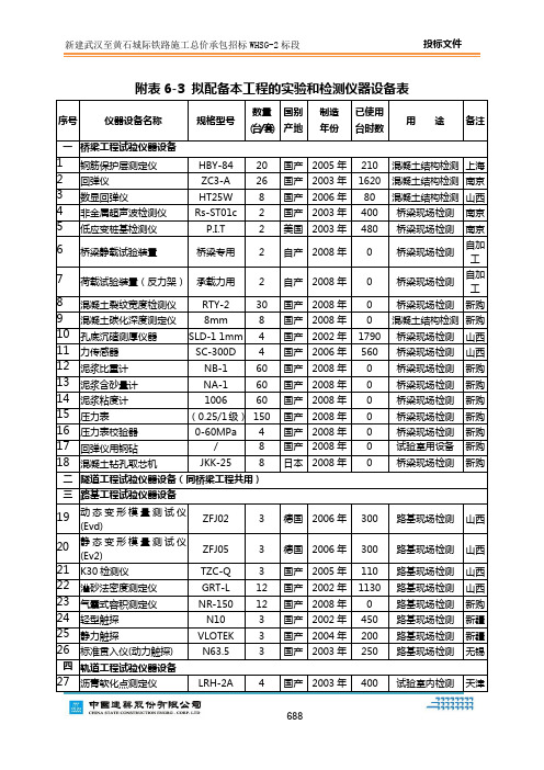
表6-3_拟投入本工程的实验和检测仪器表 2
67
混凝土抗裂试模
425×305×100
150
国产
2008年
0
试验室用设备
新购
68
试模(塑料)
150×150×150
3600
国产
2008年
0
试验室用设备
新购
69
试模(塑料)
100×100×400
500
国产
2008年
0
试验室用设备
新购
70
试模(塑料)
100×100×100
500
国产
2008年
0
试验室用设备
国产
2008年
0
试验室用设备
新购
125
洛氏硬度仪
HR-150A
4
国产
2005年
1200
试验室内检测
北京
126
锚具静载试验装置
/
1
国产
2008年
0
试验室用设备
新购
127
钢筋标距仪
手动
8
国产
2008年
0
试验室用设备
新购
128
钢筋冷弯冲头
8~125mm
16
国产
2004年
4900
试验室用设备
北京
129
游标卡尺
2003年
400
试验室内检测
天津
40
光电测温计
TRG
4国产Leabharlann 2005年400试验室内检测
南京
41
恒温水浴
/
4
国产
2008年
0
试验室用设备
新购
五
通用试验仪器设备
MTL8000 IO modules(MTL8000输入输出模块说明书)
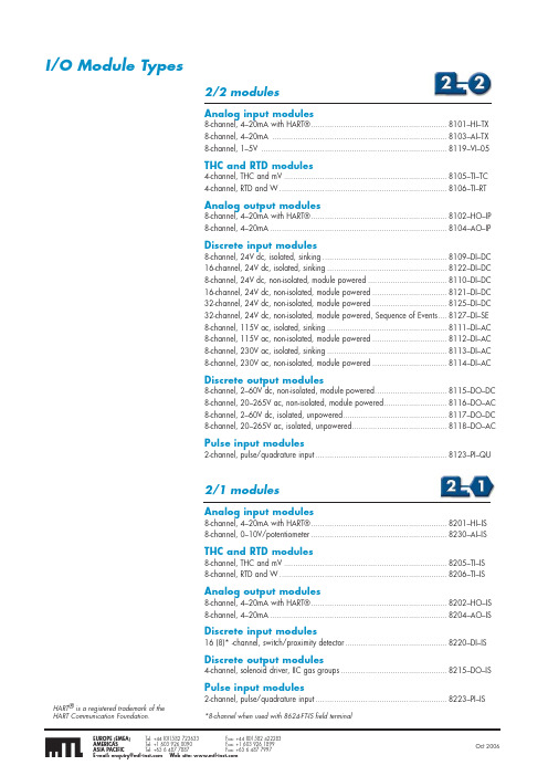
I/O Module Types2/2 modulesAnalog input modules8-channel, 4–20mA with HART® ............................................................8101–HI–TX 8-channel, 4–20mA .............................................................................8103–AI–TX 8-channel, 1–5V ..................................................................................8119–VI–05THC and RTD modules4-channel, THC and mV ........................................................................8105–TI–TC 4-channel, RTD and W ..........................................................................8106–TI–RTAnalog output modules8-channel, 4–20mA with HART® ............................................................8102–HO–IP 8-channel, 4–20mA ..............................................................................8104–AO–IPDiscrete input modules8-channel, 24V dc, isolated, sinking .......................................................8109–DI–DC 16-channel, 24V dc, isolated, sinking .....................................................8122–DI–DC 8-channel, 24V dc, non-isolated, module powered ...................................8110–DI–DC 16-channel, 24V dc, non-isolated, module powered .................................8121–DI–DC 32-channel, 24V dc, non-isolated, module powered .................................8125–DI–DC 32-channel, 24V dc, non-isolated, module powered, Sequence of Events ....8127–DI–SE 8-channel, 115V ac, isolated, sinking .....................................................8111–DI–AC 8-channel, 115V ac, non-isolated, module powered .................................8112–DI–AC 8-channel, 230V ac, isolated, sinking .....................................................8113–DI–AC 8-channel, 230V ac, non-isolated, module powered .................................8114–DI–ACDiscrete output modules8-channel, 2–60V dc, non-isolated, module powered ................................8115–DO–DC 8-channel, 20–265V ac, non-isolated, module powered ............................8116–DO–AC 8-channel, 2–60V dc, isolated, unpowered ..............................................8117–DO–DC 8-channel, 20–265V ac, isolated, unpowered ..........................................8118–DO–ACPulse input modules2-channel, pulse/quadrature input ..........................................................8123–PI–QUAnalog input modules8-channel, 4–20mA with HART® ............................................................8201–HI–IS 8-channel, 0–10V/potentiometer ............................................................8230–AI–ISTHC and RTD modules8-channel, THC and mV ........................................................................8205–TI–IS 8-channel, RTD and W ..........................................................................8206–TI–ISAnalog output modules8-channel, 4–20mA with HART® ............................................................8202–HO–IS 8-channel, 4–20mA ..............................................................................8204–AO–ISDiscrete input modules16 (8)* -channel, switch/proximity detector .............................................8220–DI–ISDiscrete output modules4-channel, solenoid driver, IIC gas groups ...............................................8215–DO–ISPulse input modules2-channel, pulse/quadrature input ..........................................................8223–PI–IS*8-channel when used with 8624-FT-IS field terminalHART ® is a registered trademark of theHART Communication Foundation.I/O Modules - Overview GeneralDefault/Power-up conditionsThese modules use the following values when they power up.Module modeNormal (not “failsafe”)Active/inactiveAll channels power up in the active state.Alarms All alarms are made inactive by having their values set to high or low extremes, as appropriate.Dead Zone0 (i.e. all changes of A/D data are reported for an active channel)Software Filtering Disabled.PassthroughPassthrough messages to HART instruments are always allowed.Visual indicatorsChannel “Status” LED (yellow)An error – i.e. a flashing LED – could be as a result of any of the following conditions:a) a loss of HART signal, b) an error in the A/D converter, c) a NAMUR alarm orAnalog Input Modules - 4-20mAGeneralThe 4–20mA AI modules provide digitised data and status information from 4–20 mA current loop sensors.HART ® capabilityAI modules “with HART” can obtain information from HART instruments of protocol revision 5.0 or later. Each channel can communicate with a single HART instrument. HART universal command 3 is used to gather up to 4 dynamic variables and status from each HART instrument. This provides more process information to the control system from each device. Greater accuracy can also be achieved by eliminating A/D and D/A errors.In addition, HART pass-through may be used for device configuration, calibration and advanced diagnostics.Input samplingThe AI modules have eight user-channels that are sampled every 27ms (2/2) or 33ms (2/1).Data formatThe input signal is stored as a 16-bit unsigned value. In this range 0 is equivalent to 0mA and 65,535 is equivalent to 25mA. Any digital HART data is stored in its original IEEE754 floating point format.FilteringThe Analog Input modules use a first-order software filter that provides 12dB attenuation at the Nyquist frequency of the algorithm. The filter supports a set of options that can be matched with control algorithm execution rates.Input alarmsFour configurable alarm levels are provided for each channel—two high and two low (see figure below). When an input value exceeds an alarm limit a flag is set and the BIM gets a new alarm status.Alarm deadbandThe Alarm Deadband prevents the alarm from tripping on and off because of system noise. It can be configured for each channel and is always set on the ‘inner’ side of the alarm limit to be, typically, greater than the system noise in the plant. If an alarm is activated, it will remain until the input moves the full extent of the deadband towards a “safer” value.The Hi-Hi and Lo-Lo alarms support the NAMUR recommendations, i.e. if the alarm limit is set less than 3.6mA (Lo-Lo), or greater than 21.0mA (Hi-Hi), the alarms must be active for 4 seconds before the alarm is set. The Deadband does not apply to NAMUR alarms. If the alarm limits are set at values between the NAMUR limits, the alarms function normally.Dead zoneEach channel has a definable "dead zone". This is to reduce the need for the module to report to the BIM every minor change in input value. If the input value differs by the amount defined by the Dead Zone, or more, then the new value is reported, otherwise it is not. This reduces traffic on the internal bus which improves the system response time. If the Dead Zone value is set to zero (the default), then every input value read will set a 'New Data' flag, and be reported.Module operating statesNormal/Failsafe modeThe AI modules support failsafe mode as defined in the earlier I/O module introductory section. When not in failsafe the module adopts Normal mode.Channel Active/InactiveA channel can be made active or inactive individually. When a channel is made inactive inputs will not be processed.HART ® is a registered trademark of the HART Communications Foundation.Monitored Channel Value VHi Alarm clearedDeadbandsLo Alarm limitLo Lo Alarm limitHi Alarm limitHi Hi Alarm limitHi Hi NAMUR Alarm clearedTimeInput Value p VHi Alarm setHi Hi Alarm clearedHi Hi Alarm setHi Hi NAMUR Alarm set (4s delay)Lo Alarm setLo Alarm clearedLo Lo Alarm clearedLo Lo Alarm setLo Lo NAMUR Alarm set (4s delay)Lo Lo NAMUR Alarm clearedAnalog Input Modules - THC and RTDInput alarmsThe modules provide two configurable alarm levels for each channel—a high limit and a low one. See figure.When an input value exceeds an alarm limit the appropriate alarm bit (high or low) is set in the channel status byte. In addition, the “new data” signal is set to allow the controller to collect the new alarm status information and the affected channel LED will flash.Alarm deadbandThe alarm deadband (not shown on the diagram) is fixed at 1%.Dead zoneEach channel has a definable "dead zone". This is to reduce the need for the module to report to the B IM every minor change in input value. If the input value differs by the amount defined by the Dead Zone, or more, then the new value is reported, otherwise it is not. This reduces traffic on the internal bus which improves the system response time. If the Dead Zone value is set to zero (the default), then every input value read will set a 'New Data' flag, and be reported.Open sensor detectionWhen configured to do so, the modules will detect an open circuit sensor and report it within 10 seconds. When this occurs a status bit is set in the module and the affected channel LED flashes. The detection options for the two module types are configurable as follows:THC and mVOff, drive upscale or drive downscale RTD and resistance Off or drive upscaleThese choices can be made for each channel.Monitored Channel Value VTimeInput Value pVLo Alarm limitLo Alarm setLo Alarm clearedHi Alarm limitHi Alarm se t Hi Alarm clearedAnalog Output Modules - 4-20mAGeneralThe 4–20 mA AO modules use a single D/A converter in a sample and hold configuration to drive each of the output channels. The processor sets the current value for each of the active channels once every 20ms. Any requested output values below 1mA are clamped to 1mA to ensure that the open-loop detection mechanism is always operable.To verify that active output channels have current flowing to the field, the processor reads a hardware signal every time an output is written to the D/A converter. If the signal indicates “no current flowing”, i.e. < 1mA, for 50 consecutive scans (i.e. one second), an Open-Loop Detection failure is set for that channel.HART ® capabilityAO modules “with HART” are compatible with all HART devices of protocol revision 5.0 or later. Each channel can communicate with a single HART instrument and supports HART communication with the wide range of HART valve positioners now available. HART universal command 3 can be used to gather up to 4 dynamic HART variables such as valve position, air pressure, etc., together with HART status variables. These are scanned by the B IM and may be communicated over the LAN for easy integration into the control system.In addition, HART pass-through may be used for device configuration, calibration and advanced diagnostics.Data formatThe output data has a resolution of 12 bits but is stored as a 16-bit unsigned value. In this range 0 is equivalent to 0mA and 65,535 is equivalent to 25mA.Module operating statesFailsafe mode The module supports failsafe mode as defined in the earlier I/O module introductory section. When put in failsafemode the output can be made to adopt oneof the following options.HART ® is a registered trademark of the HART Communications Foundation.GeneralDI modules can accept up to 8, 16 or 32 discrete inputs, from dry contacts, NAMUR standard proximity detectors, or switched voltages, depending upon module type. The source voltage for field switching can be provided through the module or from an independent supply out in the field.In operation, the input voltage is compared against a threshold voltage to create a ‘true’ or ‘false’ condition. If the inputs are from Zone 2/ Zone 1 or Zone 0 hazardous areas, the appropriate (2/1) module provides certified isolation for these signals.A pulse counter is also included which can count the number of input pulses for each of the channels.Input filterAn input filter can be set individually for each channel to introduce a delay period that allows the input to settle to a stable value.When switched off, the bandwidth of the DI input is 250Hz (100Hz for 2/1 modules). The timeout filter can introduce a timeout delay of between 2 and 512ms in 2ms steps for 2/2 modules and between 3 and 512ms in 3ms steps for 2/1 modules. Alternatively, preset values of “Fast” (22ms) or “Slow” (258ms) may be used.LatchAny channel input can be configured to be “real time” or latched. If the latch feature is enabled, the polarity can also be set so that an input signal that goes:◆high will be held high◆low will be held lowuntil the latch is released by a command from the controller. All channels are latched independently and can be cleared simultaneously, or independently, bya Write instruction to the module’s latch resetregister. If controlled by a BIM this will occurautomatically in 2 to 3 seconds.Line fault detection(2/1 only)When enabled, this will cause a flag to beset to indicate a short or open circuit fault.Low-frequency pulsecounterThe DI modules contain a continuouslyrunning 16-bit pulse counter that countseach low-frequency pulse received on theinput. The maximum pulse rate, with thetimeout filter switched off, depends upon themodule selected; consult the individual datasheets for details. With the filter active, themaximum pulse rate will be determined bythe timeout period used. In order to start aparticular count the counter must be reset tozero by a host instruction. When the counteroverflows (i.e. > 65,536 counts) it willrestart from zero.Module operating states“Failsafe” modeThe module supports failsafe modeas defined in the earlier I/O moduleintroductory section.Channel Active/InactiveEach channel can be made active orinactive individually. When a channel ismade inactive:◆inputs are not processed—i.e. the lastinput value is held and not refreshed◆channel events are not generated◆the counter is not incrementedPower-up conditionsOn power-up, or if a reset is executed,the configuration will automatically adoptpredefined states:Module mode:Normal (not “failsafe”)Channel types:All latches and filters are offActive/Inactive:All channels power-up in the Active stateVisual indicatorsChannel “Status” LED (yellow)On the DI modules the yellow “Status”LED reacts in the following way to moduleconditions.Note: the LED may appear to flash when the inputgoes high and low repeatedly.GeneralDO modules can provide up to 4 or 8 discrete outputs, depending upon module type. Continuous switched loads of up to 1A are directly achievable with these modules. Relays rated at 3, 6 and 10A are also available for switching larger load currents. Line fault detection is provided on the 2/1 modules for both open and short-circuit conditions.Output ModeThe DO module outputs may be configured for one of three different types of output:◆ Discrete◆ Single pulse◆ Continuous pulseDiscreteThe B us Interface Module (B IM) signals an ON or OFF condition on demand.Single Pulse(See Notes 1 & 2)This is an individual “single-shot” action, creating a single ON pulse of specified duration that occurs at a definable time. The pulse on-time can be varied between 2ms and 130s in increments of 2ms. If a new ON command (i.e. trigger) is given during the ON period the pulse will restart. If a new pulse width is supplied during the ON period, it will not take effect until the next ON period.A pulse can experience a small amount of time dither that depends upon the amount of Railbus activity. This can be ± 1% of the pulse width or ± 3.5ms, whichever is the longer.Continuous Pulse(see Notes 2, 3 & 4)This type of output provides a continuous pulse train that is defined by the pulse on-time, and the pulse period (the time between the start of each ON time). The pulse period is configurable to any value between 4 ms and 130,000ms in 2ms steps. The pulse on-time is the same as for the momentary action described above. The on-time must not exceed the setting for the pulse period. (See also the above note regarding AC modules.)Pulses can experience a small amount of time dither that depends upon the amount of Railbus activity. This can be ± 1% of the pulse period, or ± 3.5ms, whichever is the longer. Continuous pulse operation has two distinct modes—static and dynamic. When in static mode, the pulse parameters are cleared from memory when the channel is made inactive; in dynamic mode the values are retained for use when the channel is made active once again.Line Fault detection(2/1 only)When enabled, this will cause a flag to beset to indicate a short or open circuit faulteven when channel output is in OFF state.Module operating statesFailsafe modeThe module supports failsafe modeas defined in the earlier I/O moduleintroductory section, with the following twoadditions:1) Channel using “Configuredfailsafe values”In this mode, the module will force theoutputs to predefined levels— defined on aper channel basis.On entering “failsafe”:a) If channel is in Static mode ofoperation:Pulse mode is disabled and the channelis configured as a latched output and isdriven to its failsafe value.b) If channel is in Dynamic mode ofoperation:If in single pulse (momentary) mode,the configuration is not cleared, but theoutput is driven to its failsafe value.On leaving failsafe:Channel will adopt the mode definedbelow for a channel going frominactive to active state2) Channel using “Hold last value”If the module goes into failsafe during asingle pulse, it is allowed to complete thepulse before adopting the failsafe state. Alatched (discrete) output will remain at itscurrent value.Channel Active/ InactiveEach channel can be made active orinactive individually.When a channel is made inactive the outputis turned OFF (i.e. de-energised).When a channel changes from inactive toactive the following situations apply:a) If channel is in Static mode ofoperation:It becomes a latched output and willremain so until reconfigured by theBIM.b) If channel is in Dynamic mode ofoperation:The channel will resume operation withits previous configuration and output.Power-up conditionsOn power-up, or if a reset is executed,the configuration will automatically adoptpredefined states:Module mode:Normal (not failsafe)Channel typesAll channels are configured as DiscreteoutputsActive/InactiveAll channels power-up in the InactivestateLine fault detection (2/1 only)Disabled on all channelsVisual indicatorsChannel “Status” LED (yellow)On the DO modules the yellow “Status”LED reacts in the following way to moduleconditions.Note: the LED may appear to be flashing wheninput goes high and low repeatedly.Notes:1. This action is only available in Static mode.2. AC modules will react differently to the on-timelength and trigger time. The module can onlybe triggered ON during a zero crossing ofthe AC waveform; similarly, the module canonly switch OFF at a zero crossing point. Theminimum on-time is therefore restricted to halfthe total period of a regular waveform.3. Continuous pulse operation is supported onlyby Version 2 models of BIMs 8502 and 8505.4. On 2/2 modules, this action is only availablein Static mode.Generalto measure:◆frequency◆acceleration / rate◆number of pulses (i.e. counter)When combined, they provide:◆rfrom quadrature encoding devices outputs and one digital input to gate (start/ stop) the channel 1 internal counter. Pulse inputsInputs types accepted are:◆P roximity detectors(NAMUR/DIN19234)◆ Current inputs◆ Voltage inputs◆Switch / electro-mechanical inputs input can be set to suit the application. Dynamic datachannel, from the signal pulses received. FrequencyThe default is the rising edge.There are ten frequency measurement ranges.should be considered as “out-of-range”. Accelerationnegative value is a decrease in the rate.FilteringThe module has a hardware filter which can be used to minimise the effects of contact bounce. The available settings are 1, 5, 20 kHz and Off.AlarmsHigh / Low alarmsHigh and low alarms can be configured for each channel. When the input value goes beyond an alarm limit, channel and module flags are set, the channel LED flashes and, if configured, the channel’s digital output state will change.Acceleration alarmsAn acceleration alarm limit can also be set. If the limit is exceeded the actions taken are identical to those for the high/low alarms. Alarm deadbandA deadband can be specified for the high, low and acceleration alarms. This provides hysteresis to avoid repetitive alarms in noisy signal environments.Missing pulse alarmBoth channels can be configured to detect a “missing pulse”. If no input pulse is detected for a defined time period an alarm is signalled in the same way as the high/low alarms.The alarm is cleared on receipt of a pulse or on reconfiguration of the alarm. The time period is restarted after each sample period in which at least one pulse occurs.Line Fault DetectEach channel can be configured to sense an open or a short circuit condition on inputs. On detection, the actions are those for the high/low alarms.On fault, the BIM can: report the frequency value as being at the top or the bottom of the range, freeze the counter, set the acceleration to zero; depending on how the BIM is configured.Control dataThe host can write data to control each channel counter. The available parameters are: start, stop, set, reset and preset value. Digital outputsB oth digital output channels can reflect the status of the inputs by indicating:◆frequency or acceleration alarm◆counter preset value reached while themain channel can also output:◆quadrature forward or reverse signal◆scaled retransmission (a “divided by N” version of the input)Pulse Input Modules - 2-channel pulse/quadratureGeneralSequence of Events (SOE) recording is used to capture each of the events that occur during a shut-down or trip sequence. Such information is invaluable in determining the cause of such an event.In the course of such a sequence, events often take place very rapidly throughout the process area. The SOE module and its companion Event Logger software provide a means for recording these events and, because highly accurate time stamps are used, the precise order in which they occurred can be determined.8127-DI-SE is a 32-channel SOE module designed to monitor the status of digital inputs and to record any state changes to an internal buffer. Each state change is time-stamped to the nearest ¼ millisecond.The contents of the buffer are periodically transferred to the controller. Each module has a buffer capacity of 512 events, which it can transfer to the controller in about 500ms, consequently, approximately 1000 events per second can be captured.SOE Event Logger software The Event Logger software is provided with all MOST Workbench products. This software collects time-stamped data from the controller and merges information from multiple controllers into a chronological journal before exporting the data to standard event viewers, such as Wonderware’s InTouch. Other data export options include OPC Event format or a basic text file.The event logging software can also be used to record events other than SOE activity. For example, it can be used to record changes of state in the controller, such as when control is switched between master and slave controllers. It could be used to record when an analogue limit has been exceeded or when a digital module changes state. This powerful capability enables all critical events in the process to be recorded, providing a complete picture for further analysis.Sequence of Events ModuleBenefits◆ More accurate event sequencingAll logged events are time stamped using 1/8ms resolution for 1/4ms accuracy. The controller uses Network Time Protocol (NTP) to assure time stamp accuracy between modules across the network. When using NTP, all controllers are synchronized across the network to ± 3ms, resulting in very accurate event sequencing.◆ Identify problems quicklyEach SOE input has a unique line-fault detection feature to identify a short circuit or open circuit on each input. Problems are identified immediately for correction, saving considerable maintenance time.◆ Simplifies field wiringField circuits are module-powered, eliminating the need to “daisy chain” power supply wiring at field terminals. Field circuits are powered with a minimum of wiring and termination effort.◆ Locate SOE modules in the process Like the rest of the control platform, SOE modules can be located in your process, next to your field devices in order to record events locally on a more reliable & timely basis.◆ Easy integration with otherapplicationsEvents from multiple modules and controllers can be stored in a single SOE Event Logger providing an easy interface to other applications. 32 Discrete ChannelsThe 8127-DI-SE has 32 discrete input channels and each channel can be configured as either an SOE input or a standard discrete input.SOE input signals can also be used as standard discrete inputs as part of any control strategy. Each module can buffer up to 512 events.Events are communicated to the controller, which uses Network Time Protocol (NTP) to accurately convert the module’s time stamp data to real time. The SOE Event Logger, which constantly polls the controller for new events (typically every 2 seconds), collects each time-stamped event. After recording the events, the Event Logger sends an acknowledgement to the controller, which then clears the event from its memory.The controller retains all events until all active Event Loggers acknowledge them. Multiple Event Loggers can be used for redundant event recording and will always have consistent time stamps since all events are time stamped by the controller.Events are displayed by the SOE Data Retrieval Client. Following data retrieval, the user can choose to email the SOE data, Print it or Save it to a CSV file. The user can create a custom report easily by selecting thecolumns to be viewed and printed.See also the 8618-FT-MT field terminal for custom termination options.8-channel Analog Input◆ 8 single-ended 4-20mA input channels ◆ non-incendive field circuits ◆ HART pass-through◆ HART variable and status reporting ◆ 2- or 4-wire transmitters ◆ open and short circuit detection ◆ 24V dc bussed field power required MODULE SPECIFICATIONSee also System SpecificationINPUTSNumber of channels .......................................8, single-ended Nominal signal range (span) ...............................4 to 20mA Full signal range ...................................................1 to 23mA Line fault detectionShort circuit current .....................................................> 23.5mA Open circuit current ......................................................< 0.5mA Output voltage (@ 20mA) ...................................13.5V (min.)Output current ..................................................32mA (max.)Accuracy (over temp range) .........................± 0.1% of span Resolution ....................................................................16 bits Repeatability ....................................................0.05% of span Isolation(any channel to Railbus).................................................100V ac (between channels) .............................................................noneCONFIGURABLE PARAMETERSAlarms ....................................high, high-high, low and low-lowAlarm deadband (hysteresis ) er defined value Input filter time constant er defined value Input dead zone er defined value Drive on failsafe ...................... disabled /upscale /downscale Channel status ................................................ active /inactive HART variable and status reporting ........... enable /disableRESPONSE TIMESignal change to availability on Railbus4–20mA mode ........................................................27ms (max.)HART mode .....................................................0.75s per channelSAFETYFM non-incendive field wiring parameters (each channel) ....................V oc = 28.7V; I sc = 33mA; C a = 0.17µF; L a = 11.0mHPOWER SUPPLIESRailbus (12V) current .......................................100mA (typ.) ...........................................................................150mA (max.)Bussed Field Power 2-wire Tx .......................300mA (max.) (@ 24V dc ±10%) 4-wire Tx .........................60mA (max.)MECHANICALModule Key Code .............................................................A1Module width ...............................................................42mm Weight ............................................................................200g4–20mA with HART®8101-HI-TXFIELD TERMINALS (2-WIRE TX)FIELD TERMINALS (4-WIRE TX)HART ® is a registered trademark of the HART Communication Foundation.。
ATMT自动转换开关
环境温度
ATMT可以在以下温度条件下运行: 电气和机械特性适用于环境温度-5oC ~ +70oC -35oC时可确保合闸
贮存条件: -25oC ~ +85oC
EMC电磁兼容性
p 静电放电 p 射频电磁场 – 辐射抗扰度 p 电快速瞬变脉冲 p 浪涌冲击 p 射频电磁场 – 传导抗扰度 p 辐射等级(CISPR11)
应用领域
ATMT自动电源转换系统全面适用于工 业、基础设施、公共建筑、能源和民 用住宅等领域,特别满足电厂和工业 领域的特殊需求。
产品概述
符合标准
p IEC 60947-1 p IEC 60947-2 p IEC 60947-6-1 p GB14048.1-2008 总则 p GB14048.2-2008 断路器 p GB14048.11-2008 自动转换开关
ATMT型号说明
ATMT
40
型号
额定电流
ATMT-2A(2B) ATMT-3A(3B)
ATMT-TA/TB
3P
2A
T
极数 3极 4极
控制器类型 2A 2B 3A 3B TA TB
附件
T
控制器通讯模块
OF
ON/OFF指示触点
SDE
"故障脱扣" 指示触点
CE/CD/CT 抽架指示触点
MN
欠压脱扣
L
机械连锁
3
产品特性
ATMT标准产品特性
共同特性 极数 额定绝缘电压(V) 额定冲击耐受电压(kV) 额定工作电压(V AC 50/60Hz) 适用于隔离 污染等级
依照IEC 60974-6-1 & GB14048.11-2008定义的电气特性 额定电流 (A) 第4极额定电流 (A) 极限分断能力 (kA rms) V AC50/60 Hz
JBL音响系列产品参数

目录JBL音响系列 (6)JBL 3635 (6)JBL 3677 (6)JBL 3678 (7)JBL 3731 (8)JBL 3732 (9)JBL 4641 (10)JBL 4642A (10)JBL 4645C (11)JBL 4670D (12)JBL 4675C (12)JBL 4675C-4(8)LF (13)JBL 4722/4722N (14)JBL 4732 (15)JBL 5672 (16)JBL 5674 (17)JBL 8320 (17)JBL 8340A (18)JBL 8350 (19)JBL AC15 (19)JBL AC16 (20)JBL AC18/26 (21)JBL AC18/95 (21)JBL AC25 (22)JBL AC26 (22)JBL AC28/26 (23)JBL AC28/95 (24)JBL AL6115 (24)JBL AM4200/64 (26)JBL AM4200/95 (27)JBL AM4215/64 (28)JBL AM4215/95 (29)JBL AM4315/64 (31)JBL ASB4128 (32)JBL ASB6118 (33)JBL BC Series Cinema (33)JBL 3252N和3252 (34)JBL4181 (35)JBL 8281 (37)JBL CBT 100LA (38)JBL CBT 70J (40)JBL CBT 70JE (41)JBL CONTROL 1 PRO (42)JBL CONTROL 100 系列 (43)JBL CONTROL 23 (43)JBL CONTROL 25AV (44)JBL CONTROL 29AV-1 (46)JBL CONTROL 30 (47)JBL CONTROL 300 系列 (49)Control 328C/328CT (49)Control 321C/321CT (50)Control 321C/321CT (50)Control 312S (51)MTC-300BB8 (51)MTC-300SG12 (51)MTC-300RG8 (52)MTC-300T150 (52)JBL CONTROL 5 (53)JBL CONTROL 924C/924CT (54)JBL CONTROL 925 (56)JBL CONTROL 926C/926CT (58)JBL CONTROL 928 (59)JBL CONTROL CRV (61)JBL CONTROL SB210 (63)JBL CSA-2120 2 x120W 音频放大器 (64)JBL CSM-21 (65)JBL CSM-32 公共广播放大器 (67)JBL CSS-1S/T (69)JBL CSS-8006BM 吸顶扬声器 (71)JBL CST-2120 70V/100V 变压器套件 (72)JBL EON 210P (73)JBL EON 305 (74)JBL EON 315 (75)JBL EON 510 (76)JBL EON 515 (77)JBL EON 515XT (78)JBL EON 518S (79)JBL JRX112M (80)JBL JRX112Mi (81)JBL JRX115 (82)JBL JRX115i (83)JBL JRX118S (84)JBL JRX118SP (85)JBL KP610 (86)JBL KP612 (88)JBL KP615 (89)JBL KP618S (90)JBL KS308 (92)JBL KS310 (93)JBL KS312 (94)JBL LSR4312P (95)JBL LSR4326P (96)JBL LSR4328P (99)JBL MDD200 系列音箱 (103)JBL MP510 (104)JBL MRX512M (105)JBL MRX515 (105)JBL MRX518S (106)JBL MRX525 (107)JBL MRX528S (107)JBL PRX400 系列 (108)PRX412M12“两路舞台监听扬声器系统 (108)PRX415M15“两路舞台监听扬声器系统 (109)PRX42515寸两分频扬声器系统 (110)PRX418S18“重低音 (110)JBL PRX512M (111)JBL PRX515 (112)JBL PRX518S (113)JBL PRX525 (114)JBL PRX535 (114)JBL PRX612M (115)JBL PRX615M (116)JBL PRX618S (117)JBL PRX618S-XLF (118)JBL PRX625 (118)JBL PRX635 (119)JBL SRX700 系列 (120)SRX712M: (120)SRX715 (121)SRX718S (121)SRX722 (122)SRX725 (122)SRX728S (122)SRX738 (123)JBL SRX712M (123)JBL SRX715F (124)JBL SRX722F (126)JBL SRX725F (126)JBL SRX728S (127)JBL SRX738F (128)JBL STX800 系列 (129)STX812M 12”两分频,低音反射式,舞台返听/通用式 (129)STX815M 15”两分频,低音反射式,舞台返听/通用式 (130)STX825 双15”两分频,低音反射式 (131)STX835 Dual 15" 双15”三分频,加载中/高音号筒,槽孔式加载低音 (132)STX818S 单18”低音反射式套装选配件 (133)STX828S 双18”低音反射式 (134)JBL VP7212-64DPAN (135)JBL VP7212-95DPAN (135)JBL VP7215-64DPAN (136)JBL VP7215-95DPAN (137)JBL VP7315-64DPAN (138)JBL VPSB7118DPAN (138)JBL VRX915M (139)JBL VRX915S (140)JBL VRX918S (140)JBL VRX918SP (141)JBL VRX928LA (141)JBL VRX932LA-1 (142)JBL VRX932LAP (142)JBL VT4880 (143)JBL VT4881A (143)JBL VT4881ADP (144)JBL VT4882 (144)JBL VT4882DP (145)JBL VT4883 (145)JBL VT4886 (146)JBL VT4887A (147)JBL VT4887ADP (147)JBL VT4888 (148)JBL VT4888DP (149)JBL VT4889 (150)SHURE 话筒系列 (150)Shure Beta 52A (150)Shure Beta 56A (152)Shure Beta 57A (153)Shure Beta 58A (154)Shure Beta 87A (155)Shure Beta 87C (156)Shure PGX1 (158)Shure PGX2 (158)Shure PGX4 (159)Shure PSM200 (159)Shure SLX (162)Shure SLX1 (164)Shure SLX2 (165)Shure SLX4 (166)Shure SM48 (168)Shure SM57 (169)Shure SM58 (170)Shure SM81 (171)Shure SM87A (172)Shure SM94 (173)Shure ULX (175)Shure ULX1 (177)Shure ULX2 (179)Shure ULXP4 (180)JBL音响系列JBL 3635影院次低频扬声器规格频率范围28Hz - 500kHz (-10dB) 频率响应38Hz - 100kHz (±3dB) 额定功率300W分频点100Hz灵敏度100dB @ 1W,1m阻抗8 欧姆低频驱动器(S) 2042H体积(高x 阔x 深) 1168 x 651 x 368mm 净重(每只51kgJBL 3677影院扬声器规格频率范围40Hz - 20kHz (-10dB) 频率响应45Hz - 12kHz (±3dB) 额定功率250W覆盖角度水平:90°垂直:40°分频点 1.2kHz灵敏度99dB SPL @ 1W,1m 阻抗8 欧姆低频驱动器(S) 2035H高频驱动器2416-1号角2373低频-高频-体积(高x 阔x 深) 765 x 651 x 292 mm JBL 3678规格频率范围30Hz - 20kHz (-10dB) 频率响应45Hz - 12kHz (±3dB) 额定功率300W覆盖角度水平:90°垂直:90°分频点1kHz灵敏度98dB SPL @ 1W,1m 阻抗8 欧姆低频驱动器(S) 2226H高频驱动器2425HS号角2342系统组合低频:3678 – HF高频:3678 - HF体积(高x 阔x 深) 1019 x 651 x 292 mmJBL 37313731 三分频银幕线阵列•专门用于后期制作室、VIP 电影厅、审片室•保证了高品质的声音,同时适应了小型放映场所的需要•应用了多项JBL 的专利先进技术•可选择以双功放或三功放驱动•出厂预装及指向调校完毕规格频率范围(-10dB) 30Hz - 20kH频率响应(±3dB) 40Hz - 19kHz指向性因数(Q 10.0指向性指数(DI) 10dB最大声压级125dB @ 1m分频点频率350Hz, [1.2kHz]灵敏度103dB, 2.83V@1m阻抗8 欧姆额定功率LF: 600WM/HF: 150W, [HF:85W]系统组合5641/3732 -M/HF体积(高x 阔x 深) 1600 x 762 x 450 mm 净重(每只) 51.8 kgJBL 37323732 三分频银幕线阵列•可用于最大300 座位的影厅•应用了与4632 一样的先进的技术•可以满足各种预算•可选择以双功放或三功放驱动•出厂预装及指向调校完毕规格频率范围30Hz - 20kHz (-10dB)频率响应40Hz - 19kHz (±3dB)指向性因数(Q) 10.0指向性指数(DI) 10dB最大声压级125dB @ 1m分频点频率350Hz, [1.2kHz]灵敏度103dB, 2.83V@1m阻抗: 4 欧姆额定功率LF: 500WM/HF: 150W, [HF:85W]系统组合3639/3732 -M/HF[4639/3732 - M/HF - T]体积(高x 阔x 深) 1937 mm x 762 mm x 450 mm 净重(每只) 77.9kgJBL 46414641 影院次低频扬声器•性能价格比优越的次低频系统•单460-mm(18英寸)JBL 2241 VGC TM (孔隙冷却技术)2241H低频换能器规格频率范围25Hz - 500kHz (-10dB)频率响应(±3dB) -额定功率600W分频点100Hz灵敏度100dB @ 1W,1m阻抗8 欧姆低频驱动器(S) 2042H体积(高x 阔x 深) 1010 mm x 674 mm x 450 mm 净重(每只) 60kgJBL 4642A4642A 影院次低频扬声器•双460-mm (18英寸)单元•应用了VGC TM (孔隙冷却技术) 2241H 低频换能器•1200 瓦功率,平滑的频率响应规格频率范围(-10dB) 22Hz - 500Hz频率响应(±3dB) -额定功率1200W分频点80 to 100Hz灵敏度101dB SPL @ 1W,1m阻抗4/8 欧姆低频驱动器(S) 2 x 2241H体积(高x阔x深) 762 mm x 1219 mm x 610 mm 净重(每只) 98kgJBL 4645C4645C 影院次低频扬声器•单460-mm (18英寸) 直辐射低频反射式超低音系统•应用了2242 SVG TM (超级孔隙)技术•800 瓦输出功率规格频率范围(-10dB) To 22Hz (no EQ)频率响应(±3dB) -额定功率800W分频点80 to 100Hz灵敏度:1W,1m 97dB (40 - 100Hz)阻抗8 欧姆低频驱动器(S) 2242H体积(高x阔x深) 1010 mm x 674 mm x 450mm 净重(每只) 63 kgJBL 4670D4670D 影院扬声器•4070D 是一宽频带系统,有着出色的动态范围及均匀的覆盖。
MTK平台射频校准文件说明
[RX path loss table] GSM900_MAX_RX_LOSS = 15.000,15.000,15.000,15.000,15.000,15.000,15.000,15.000,15.000,15.000,15.000,15.0000, GSM900_MIN_RX_LOSS = -15.000,-15.000,-15.000,-15.000,-15.000,-15.000,-15.000,15.000,-15.000,-15.000,-15.000,-15.0000, GSM900_MAX_RX_LOSS_MIDDLE = 15.000,15.000,15.000,15.000,15.000,15.000,15.000,15.000,15.000,15.000,15.000,15.0000, GSM900_MIN_RX_LOSS_MIDDLE = -15.000,-15.000,-15.000,-15.000,-15.000,-15.000,15.000,-15.000,-15.000,-15.000,-15.000,-15.0000, GSM900_MAX_RX_LOSS_LOW = 15.000,15.000,15.000,15.000,15.000,15.000,15.000,15.000,15.000,15.000,15.000,15.0000, GSM900_MIN_RX_LOSS_LOW = -15.000,-15.000,-15.000,-15.000,-15.000,-15.000,15.000,-15.000,-15.000,-15.000,-15.000,-15.0000, RX 校准高中低增益下的loss 上下限
下面择取一些关键项进行解释
[8960 Initialization] 8960 GPIB Address =GPIB0::15::INSTR Time Out =5000 GSM400 cable loss = -0.4 GSM850 cable loss = -0.5 GSM900 cable loss = -0.5 DCS1800 cable loss = -0.8 PCS1900 cable loss = -0.8 TDSCDMA 1850-1930MHz cable loss = -1 TDSCDMA 2010-2025MHz cable loss = -1 TDSCDMA 1930-1990MHz cable loss = -1 TDSCDMA 2570-2620MHz cable loss = -1 TDSCDMA 2300-2400MHz cable loss = -1 (上面是仪器8960的初始化,其他仪器的初始化格式基本都这样)
MT818.1
MT818.1——第10部分:煤矿用矿工帽灯线;——第11部分:额定电压10kV及以下固定敷设电力电缆一般规定;——第12部分:额定电压1.8/3kV及以下煤矿用聚氯乙烯绝缘电力电缆;——第13部分:额定电压8.7/10kV及以下煤矿用交联聚乙烯绝缘电力电缆。
本部分为MT 818的第1部分,是对MT 818.2~ MT 818.10各部分的一般要求,本部分代替MT 818.1-1999《煤矿用阻燃电缆第1单元: 煤矿用移动类阻燃软电缆第1部分:一般规定》。
本部分与MT 818.1-1999相比主要变化如下:——删除MT 818.1-1999所有弹性体绝缘护套电缆相关内容(1999年版的附录A和附录B);——删除电缆引入装置的相关内容(1999年版的附录C);——修改了屏蔽型电缆屏蔽层结构及性能要求(见1999年版的5.3及本部分5.3);——电缆额定电压提高到8.7/10kV(见表5、表8);——依据安全标志管理规定修改了电缆标志要求(见第8章);——“系统的工作电压……1.1倍”条款后增加“并且符合《煤矿安全规程》的规定”(见3.1);——修改代号“J”定义,表示为“监视或辅助线芯”(见1999年版的表2及本部分的表2);——增加控制线芯不同标称截面的直流电阻阻值(见表3);——修改过渡电阻试验方法(见1999年版的6.7及本部分的6.6);——增加了弯曲试验台设备“发生短路和断路时能自动报警”要求(见6.10.1);——对电缆弯曲试验的弯曲半径分别改为“150mm”、“200mm”、“250mm”(见表10);——增加抗撕试验方法(见附录A);——考虑到选型问题,增加电缆相应规格载流量数据作为资料性附录(见附录B)。
本部分的附录A为规范性附录, 附录B为资料性附录。
本部分由中国煤炭工业协会科技发展部提出。
本部分由煤炭行业煤矿安全标准化技术委员会归口。
本部分负责起草单位:煤炭科学研究总院上海分院。
(建议下载)数字多用表8508a说明书中文手册p
8508A数字多用表分为模拟电路与数字电路两部分。
模拟电路以多斜率多重积分式A/D转换器为核心,数字电路以单片计算机为核心,两部分之间以光电耦合的串行通讯进行信息交换。
两部分之间在电气上完全隔离,仅靠光来实现信息的传送。
多斜率多重积分式A/D转换器是在本公司的四斜式A/D转换器基础上发展起来的。
输入被测电压在一固定的时间内接入积分器,机内参考电压也在此固定时间内多次接入,使积分器输出幅度一直保持在一定范围内。
在这一固定时间结束后,机内参考电压将积分器输出电压反向积分过零。
由于在积分的不同阶段,机内参考电压各不相同,使得在整个转换过程中即是多重积分循环,又在每个循环中出现了多种斜率。
这种转换方法,既解决了转换时间与高分辨率的矛盾,也解决了积分电路失调、噪声、积分电容介质吸咐效应等不理想因素对转换精度的影响。
从4 1/2位到8 1/2位的各种转换位数可提供速度和准确度的最佳选择,从二万分之一到二亿分之一的分辨力为用户提供了最大的便利。
众多的功能8508A将多种功能组合在一起以适应系统应用和精密测量的需要。
直流电压,直流电流,电阻测量,交流电压测量和交直流电流测量,温度测量和IEEE488.2总线接口是标准配置;比率测量和后面板接线柱输入是选件配置。
数据处理,数据存贮和测量速度、方式的变化在各个功能都可以实现。
采用自举电源的斩波稳定放大器为直流电压测量功能提供了低漂移、低噪声、高输入阻抗的优良性能,完善的输入保护电路保证各电压量程都可经受1000V过电压连续冲击。
低恒温的齐纳稳压参考源和高精度精密金属箔电阻保证了8508A的直流电压年绝对不确定度优于3.2ppm,温度系数仅为0.3ppm/℃。
交流电压功能保证1Hz至1MHz的平坦频率响应,独特的真有效值(RMS)转换器可准确测量从1%量程至100%量程的交流信号。
8508A的点频率方式(Spot)和AC/DC转换(Tfer)方式可进一步提高测量准确度。
常见焊条焊丝型号牌号对照一览表
390
490
20
-20℃
47
该焊条是50公斤级耐火耐侯钢配套的专用焊条,主要用于要求耐火耐侯的重要钢构造的焊接
230
(600℃)
—
≥25
(600℃)
—
THJ506R
E5016-G
0.10
1.00/1.50
0.50
0.025
0.030
Ni0.45/0.80
390
490
22
-40℃
THJ506-1
E5016-1
0.12
1.60
0.75
0.030
0.030
—
400
490
20
-46℃
27
适用于低温高韧性材料的全位置焊接
THJ506Fe-1
E5018-1
0.10
1.60
0.65
0.030
0.030
—
420
500/
640
22
-50℃
47
用途同THJ506-1,药皮中含有铁粉,可进步焊条熔敷效率,工艺性能好
E5010
E5011
0.20
0.50/
1.00
0.30
0.035
0.040
—
400
490
20
-30℃
27
焊接相应强度碳钢及低合金钢管环缝的全位置立向下焊接,底层焊时单面焊双面成形操作容易
THJ506
E5016
0.12
1.60
0.75
0.035
0.040
—
400
490
20
-30℃
27
适用于中碳钢及低合金钢构造的全位置焊接,焊缝具有良好的力学及抗裂性能
- 1、下载文档前请自行甄别文档内容的完整性,平台不提供额外的编辑、内容补充、找答案等附加服务。
- 2、"仅部分预览"的文档,不可在线预览部分如存在完整性等问题,可反馈申请退款(可完整预览的文档不适用该条件!)。
- 3、如文档侵犯您的权益,请联系客服反馈,我们会尽快为您处理(人工客服工作时间:9:00-18:30)。
客人名称
VF
P.O.NO.
2030500/2030530
8958
物料名称颜色
面布#SZ-1539
布号#SZ-1539;成份:100%棉染色3/1"S"斜斜纹
布;7.2安士;布封:58/59"(可裁布封57");面布颜色
有三种:黑色/BLACK,杏色/COBBLESTONE,啡
色/CAROB.
前代布#TC133X72封度:58/59",有两种颜色:半漂和黑色.
纸朴#AP88朴号#AP88;封度:36",有两种颜色:白色和灰色.
面线/底线/保险线/凤眼面线/凤
眼底线/打早面线
黑色面布用金泰#1688色604线;杏色面布用金
泰#01G8U色604线;啡色面布用金泰#0948色
604线.
及骨线/打早底线黑色面布用金泰#1688色402线;杏色面布用金泰#01G8U色402线;啡色面布用金泰#0948色
402线.
凤眼芯线
黑色面布用金泰#1688色T10线;杏色面布用金
泰#01G8U色T10线;啡色面布用金泰#0948色
T10线.
车前代布线
黑色面布用金泰#B020色604线,杏色面布用金
泰#W011白色604线,啡色面布用金泰#B020色
604线.
主唛#DS
型号:#DS(SIDE SEWN),有"VENEZIA"字.黑色
民
客人款号
721-161400
制单编号
MTB-80085A/B
洗水麦#DS
对应码数;成份:"100% COTTON";MADE IN
CHINA;洗水指示内容:MACHINE WASH
COLD WITH LIKE COLORS,ONLY NON-
CHLORINE BLEACH WHEN
NEEDED,TUMBLE DRY
LOW;RN#118640;CS11070465.
前中拉链
580/H5443/141色 4''
前中拉链
4 1/2''
前中拉链
5''
前中拉链5 1/2''
27L工字钮
型号:#V0074-168V/610E,颜色:深青古铜(DARK
ANTIQUE BRASS),有"VENEZIA"字.
腰卡#SLOJT腰卡 型号:#SLOJT,分码数.
价钱牌
价钱牌 型号:TBA/待复,分PO分码数.
挂牌#KZ(只用于黑色面布)
WASH BEFORE WEARING挂牌,型号:#KZ,正
面有"VENEZIA"字.
透明胶针
2"长,白色,跟客人批的做.
胶代
PE环保料,方代,跟客人提供的警告语印.
纸箱
箱唛的字体为粗体不小于1/4",A三B纸,纸箱不
要打钉,不用天地板.
洗水费用
裁床数量 车间数量
制表人:
日 期:
14#16#18#
MTB-80085A
51610321149
MTB-80085B
172344344
4"4"4 1/2"
68813761493
型号供应商单件用量单位总用量(加5%)仓存
SZ-1539Mingyuen
纸样师傅预计用
量:2.15Y
Y/件
TC133X72
河北金航布行
纸样师傅预计用量:0.2YY/件
AP88Freudenberg
纸样师傅预计用量:0.5YY/件
604金泰260
码/件
402金泰180
码/件
T10金泰2
码/件
604鸿利7
码/件
#DSTony labels1
个/件
民 恩 纺 织 制 衣 有 限 公 司---
核 料 单
颜色/码数
数量
B
拉链尺寸(INCH)
合计
#DSTony labels1
个/件
YKK
YKK
YKK
4号青古铜牙勿尾拉链
YKK1
条/件
27LWING SUN4
粒/件
#SLOJTAVERY DENNISON1
个/件
CHECKPOINT
1
个/件
#KZARTCO1
个/件
仓存
1
支/件
濠益胶袋厂
12件/个;18件/个件/个
振铭纸箱厂
12件/个;18件/个件/个
包装数量主管审批:仓 管:日 期:日 期:公司经费销售税金生产成本
20#22#24#26#28#
TATOL
12661149633633516
344344172172172
4 1/2"5"5"5 1/2"5 1/2"
16101493805805688
8958
应订购量实订购
量
订购单号进仓数出仓数单价金额
673
354
14
34
9062
8958
9062
2104
3134
2376
1432
374470
9062
9406
2025
5624
736
会 计:总经理:
日 期:日 期:
产品总值利润总额