Autonomously Proficient CNC Controller forHigh-Performance
三菱PLC使用说明书

→请参考FX3U系列用户手册[硬件篇] →请参考FX3UC系列用户手册[硬件篇]
2.1.1 DIN导轨安装
产品可以安装在DIN46277(宽35mm)的DIN导轨上。
1) 将 [DIN 导轨安装用沟槽的上侧 ( 右图 A)] 对准并 挂到[DIN导轨]上。
1)
2) 将产品按压在[DIN导轨]上。
- 请在产品与产品之间留出1~2mm左右的间
*2 D类接地
D类接地
*1 XD24
带屏蔽双绞线电缆
*3 DISABLE
XD 5
COMD *1
P24+
P12++ P-
带屏蔽双绞线电缆 PRESET *3
D类接地
D类接地
*2 Z相
*1 编码器的驱动电源。 请根据编码器规格,在DC24V、DC12V、DC5V中选择使用。 与FX3U-2HC连接A相、B相、Z相时,请连接与电源相匹配的端子。 此外,PRESET及DISABLE信号使用DC24V时,请与DC24V用端子(P24+,XD24)连接。
1. 产品概要
1.1 产品概要
NCP1207A中文资料

5.0 ms Timeout
Timeout Reset
380 ns
L.E.B.
CS
Demag
ÁÁÁÁÁÁMAÁÁÁXIMÁÁÁUMÁÁÁRATÁÁÁINGÁÁÁS ÁÁÁÁÁÁÁÁÁÁÁÁÁÁÁFRiÁÁÁgautirnÁÁÁeg2.ÁÁÁInteÁÁÁrnaÁÁÁl CiÁÁÁrcuiÁÁÁt ArÁÁÁchitÁÁÁectÁÁÁureÁÁÁÁÁÁÁÁÁÁÁÁSymÁÁÁbolÁÁÁÁÁÁVaÁÁlÁue ÁÁÁÁÁÁUniÁÁtÁs
© Semiconductor Components Industries, LLC, 2004
1
November, 2004 − Rev. 1
Publication Order Number: NCP1207A/D
元器件交易网
NCP1207A
Universal Network
NCP1207ADR2 SOIC−8 2500/Tape & Reel
NCP1207ADR2G NCP1207AP
SOIC−8 (Pb−Free)
PDIP−8
2500/Tape & Reel 50 Units/Tube
†For information on tape and reel specifications, including part orientation and tape sizes, please refer to our Tape and Reel Packaging Specifications Brochure, BRD8011/D.
2
FB
Sets the peak current setpoint By connecting an Optocoupler to this pin, the peak current setpoint is
1756-技术数据

Technical Data1756 ControlLogix ControllersSpecificationsControlLogix Controller Catalog Numbers1756-L61, 1756-L62, 1756-L63, 1756-L63XT, 1756-L64, 1756-L65, 1756-L71,1756-L72, 1756-L73, 1756-L73XT, 1756-L74, 1756-L75GuardLogix Controller Catalog Numbers1756-L61S, 1756-L62S, 1756-L63S, 1756-LSP, 1756-L72S, 1756-L73S, 1756-L7SP, 1756-L73SXT, 1756-L7SPXT ControlLogix Redundancy Catalog Numbers 1756-RM, 1756-RMXTTopic Page1756 ControlLogix Controllers21756 ControlLogix-XT Controllers81756 GuardLogix Controllers81756 GuardLogix-XT Controllers18Controller Memory Use20Controller Compatibility20ControlLogix Redundancy24ControlLogix Connections26ControlLogix Controller Accessories281756 ControlLogix Controllers Specifications1756 ControlLogix ControllersThe ControlLogix® controller provides a scalable controller solution that is capable of addressing a large amount of I/O points. The ControlLogix controller can be placed into any slot of a ControlLogix I/O chassis and multiple controllers can be installed in the same chassis.ControlLogix controllers can monitor and control I/O across the ControlLogix backplane, as well as over network links. T o provide communication for a ControlLogix controller, install the appropriate communication interface module into the chassis.1756-L7x ControlLogix Controllers Features and SpecificationsFeature1756-L71, 1756-L72, 1756-L73, L73XT, 1756-L74, 1756-L75Controller tasks·32 tasks·100 programs/task·Event tasks: all event triggersBuilt-in communication ports 1 port USB(1)Communication options·EtherNet/IP·ControlNet·DeviceNet·Data Highway Plus™·Remote I/O·SynchLink™·Third-party process and device networksUSB port communication Programming, configuration, firmware flash and on-line edits onlyController connections supported, max500Network connections, per network module·100 ControlNet (1756-CN2/A)·40 ControlNet (1756-CNB/D, 1756-CNB/E)·128 ControlNet (1756-CN2/B)·256 EtherNet/IP; 128 TCP (1756-EN2x)·128 EtherNet/IP; 64 TCP (1756-ENBT)Controller redundancy Full supportIntegrated motion·SERCOS interface·Analog options (encoder input, LDT input, SSI input)·EtherNet/IP (CIP Motion)Programming languages·Relay ladder·Structured text·Function block·SFC(1)The USB port is intended for temporary local programming purposes only and not intended for permanent connection. Do not use the USB port in hazardous locations.2Rockwell Automation Publication 1756-TD001E-EN-P - March 2012Rockwell Automation Publication 1756-TD001E-EN-P - March 201231756 ControlLogix Controllers SpecificationsTable 1 - Technical Specifications - 1756-L7x ControlLogix ControllersAttribute 1756-L711756-L721756-L731756-L741756-L75User memory 2 MB 4 MB8 MB16 MB32 MBI/O memory0.98 MBOptional nonvolatile memory storage 1 GB (1784-SD1 ships with every controller)2 GB (1784-SD2)Digital I/O, max 128,000Analog I/O, max 4000Total I/O, max 128,000Energy storage module·1756-ESMCAP capacitor energy storage module (removable, ships installed with every controller)·1756-ESMNSE capacitor energy storage module (removable, no residual WallClockTime power backup)·1756-ESMNRM capacitor energy storage module (nonremovable, secures controller by preventing USB connection an d SD card use)Current draw @ 1.2V DC 5 mA Current draw @ 5.1V DC 800 mA Power dissipation 2.5 W Thermal dissipation 8.5 BTU/hrIsolation voltage 30V (continuous), basic insulation type, USB port-to-system Type tested at 500V AC for 60 s USB port (1)(1)The USB port is intended for temporary local programming purposes only and not intended for permanent connection. Do not use the USB port in hazardous B 2.0, full speed (12 Mbps)Weight, approx 0.25 kg (0.55 lb)Slot width 1Module location Chassis-based, any slotChassis1756-A4, 1756-A7, 1756-A10, 1756-A13, 1756-A17Power supply, standard 1756-PA72, 1756-PA75, 1756-PB72, 1756-PB75Power supply, redundant 1756-PA75R, 1756-PB75R, 1756-PSCA2Wire category (2)(2)Use this conductor category information for planning conductor routing. Refer to Industrial Automation Wiring and Grounding Guidelines, publication 1770-4.1.3 - on USB port North American temperature code T4A IEC temperature code T4Enclosure type ratingNone (open-style)4Rockwell Automation Publication 1756-TD001E-EN-P - March 20121756 ControlLogix Controllers SpecificationsTable 2 - Environmental Specifications - 1756-L7x ControlLogix ControllersAttribute1756-L71, 1756-L72, 1756-L73, 1756-L74, 1756-L75Temperature, operatingIEC 60068-2-1 (Test Ad, Operating Cold),IEC 60068-2-2 (Test Bd, Operating Dry Heat),IEC 60068-2-14 (Test Nb, Operating Thermal Shock)0…60 °C (32…140 °F)Temperature, nonoperatingIEC 60068-2-1 (Test Ab, Unpackaged Nonoperating Cold),IEC 60068-2-2 (Test Bb, Unpackaged Nonoperating Dry Heat),IEC 60068-2-14 (Test Na, Unpackaged Nonoperating Thermal Shock) -40…85 °C (-40…185 °F)Temperature, surrounding air, max60 °C (140 °F)Relative humidityIEC 60068-2-30 (Test Db, Unpackaged Damp Heat) 5…95% noncondensing VibrationIEC 60068-2-6 (Test Fc, Operating) 2 g @ 10…500 Hz Shock, operatingIEC 60068-2-27 (Test Ea, Unpackaged Shock) 30 gShock, nonoperatingIEC 60068-2-27 (Test Ea, Unpackaged Shock) 50 g (45 g with SD card installed) Emissions CISPR 11Group 1, Class AESD immunity IEC 61000-4-2 6 kV contact discharges 8 kV air dischargesRadiated RF immunity IEC 61000-4-310V/m with 1 kHz sine-wave 80% AM from 80…2000 MHz 10V/m with 200 Hz 50% Pulse 100% AM @ 900 MHz 10V/m with 200 Hz 50% Pulse 100% AM @ 1890 MHz3V/m with 1 kHz sine-wave 80% AM from 2000…2700 MHz Table 3 - Certifications - 1756-L7x ControlLogix ControllersCertification (1)(1)When marked. See the Product Certification link at for Declarations of Conformity, Certificates, and other certification details.1756-L71, 1756-L72, 1756-L73, 1756-L74, 1756-L75c-UL-usUL Listed Industrial Control Equipment, certified for US and Canada. See UL File E65584.UL Listed for Class I, Division 2 Group A,B,C,D Hazardous Locations, certified for U.S. and Canada. See UL File E194810.CEEuropean Union 2004/108/EC EMC Directive, compliant with:·EN 61326-1; Meas./Control/Lab., Industrial Requirements ·EN 61000-6-2; Industrial Immunity ·EN 61000-6-4; Industrial Emissions·EN 61131-2; Programmable Controllers (Clause 8, Zone A & B)C-Tick Australian Radio communications Act, compliant with:AS/NZS CISPR 11; Industrial EmissionsExEuropean Union 94/9/EC ATEX Directive, compliant with:·EN 60079-15; Potentially Explosive Atmospheres, Protection ’n’·EN 60079-0; General Requirements ·II 3 G Ex nA IIC T4 XKCKorean Registration of Broadcasting and Communications Equipment, compliant with: Article 58-2 of Radio Waves Act, Clause 31756 ControlLogix Controllers Specifications1756-L6x ControlLogix Controllers Features and SpecificationsTable 4 - Features - Standard ControlLogix 1756-L6x ControllersFeature1756-L61, 1756-L62, 1756-L63, L63XT, 1756-L64, 1756-L65Controller tasks·32 tasks·100 programs/task·Event tasks: all event triggersBuilt-in communication ports 1 port RS-232 serialCommunication options·EtherNet/IP·ControlNet·DeviceNet·Data Highway Plus·Remote I/O·SynchLink·Third-party process and device networksSerial port communication·ASCII·DF1 full/half-duplex·DF1 radio modem·DH-485·Modbus via logicController connections supported, max250Network connections, per network module·100 ControlNet (1756-CN2/A)·40 ControlNet (1756-CNB/D, 1756-CNB/E)·128 ControlNet (1756-CN2/B)·256 EtherNet/IP; 128 TCP (1756-EN2x)·128 EtherNet/IP; 64 TCP (1756-ENBT)Controller redundancy Full supportIntegrated motion·SERCOS interface·Analog options (encoder input, LDT input, SSI input)·EtherNet/IP (CIP Motion)Programming languages·Relay ladder·Structured text·Function block·SFCIMPORTANT Scan time for a project loaded in a 1756-L64 or 1756-L65 controller may be slower than for the same project loaded in one of the other 1756-L6x controllers. See the Logix5000™ Controllers Instruction Execution Time and Memory Use ReferenceManual, publication 1756-RM087, for instruction execution times.Rockwell Automation Publication 1756-TD001E-EN-P - March 201256Rockwell Automation Publication 1756-TD001E-EN-P - March 20121756 ControlLogix Controllers SpecificationsTable 5 - Technical Specifications - 1756-L6x ControlLogix ControllersAttribute 1756-L611756-L621756-L631756-L641756-L65User memory 2 MB 4 MB8 MB16 MB32 MBI/O memory478 KBOptional nonvolatile memory storage 128 MB (1784-CF128)Digital I/O, max 128,000Analog I/O, max 4000Total I/O, max 128,000Replacement battery (1)(1)For Australian Mining certification applications, only a series A controller and a 1756-BA1 battery can be used. For more information, contact your local distributor or sales office.Series A: 1756-BA1, 1756-BATM, 1756-BATA Series B: 1756-BA21756-BA2Current draw @ 5.1V DC 1200 mA Current draw @ 24V DC 14 mA Power dissipation 3.5 W Thermal dissipation 11.9 BTU/hrIsolation voltage 30V (continuous), basic insulation type, RS-232 to system Controllers tested to withstand 720V DC for 60 sSerial cables 1756-CP3 or 1747-CP3, right angle connector to controller, straight to serial port, 3 m (9.84 ft)Weight, approx Series A: 0.32 kg, (0.71 lb)Series B: 0.35 kg, (0.78 lb)Slot width 1Module location Chassis-based, any slotChassis1756-A4, 1756-A7, 1756-A10, 1756-A13, 1756-A17Power supply, standard 1756-PA72, 1756-PA75, 1756-PB72, 1756-PB75Power supply, redundant 1756-PA75R, 1756-PB75R, 1756-PSCA2Wire category (2)(2)Use this conductor category information for planning conductor routing as described in the system level installation manual. See the Industrial Automation Wiring and Grounding Guidelines, publication1770-4.1.2 - on communication ports North American temperature code T4A IEC temperature code T4Enclosure type ratingNone (open-style)1756 ControlLogix Controllers SpecificationsTable 6 - Environmental Specifications - 1756-L6x ControlLogix ControllersAttribute1756-L61, 1756-L62, 1756-L63, 1756-L64, 1756-L65Temperature, operatingIEC 60068-2-1 (Test Ad, Operating Cold),IEC 60068-2-2 (Test Bd, Operating Dry Heat),IEC 60068-2-14 (Test Nb, Operating Thermal Shock)0…60 °C (32…140 °F)Temperature, storageIEC 60068-2-1 (Test Ab, Unpackaged Nonoperating Cold),IEC 60068-2-2 (Test Bb, Unpackaged Nonoperating Dry Heat),IEC 60068-2-14 (Test Na, Unpackaged Nonoperating Thermal Shock)-40…85 °C (-40…185 °F)Temperature, surrounding air, max60 °C (140 °F)Relative humidityIEC 60068-2-30 (Test Db, Unpackaged Damp Heat)5…95% noncondensingVibrationIEC 60068-2-6 (Test Fc, Operating)2 g @ 10…500 HzShock, operatingIEC 60068-2-27 (Test Ea, Unpackaged Shock)30 gShock, nonoperatingIEC 60068-2-27 (Test Ea, Unpackaged Shock)50 gEmissionsCISPR 11Group 1, Class AESD immunity IEC 61000-4-26 kV contact discharges 8 kV air dischargesRadiated RF immunity IEC 61000-4-310V/m with 1 kHz sine-wave 80% AM from 80…2000 MHz 10V/m with 200 Hz 50% Pulse 100% AM @ 900 MHz10V/m with 200 Hz 50% Pulse 100% AM @ 1890 MHz3V/m with 1 kHz sine-wave 80% AM from 2000…2700 MHzEFT/B immunityIEC 61000-4-4±4 kV at 5 kHz on communication portsSurge transient immunityIEC 61000-4-5±2 kV line-earth (CM) on communication portsConducted RF immunityIEC 61000-4-610V rms with 1 kHz sine-wave 80% AM from 150 kHz…80 MHzRockwell Automation Publication 1756-TD001E-EN-P - March 201278Rockwell Automation Publication 1756-TD001E-EN-P - March 20121756 ControlLogix Controllers Specifications1756 ControlLogix-XT ControllersThe ControlLogix-XT ™ controllers function in the same way as the traditional ControlLogix controllers. TheControlLogix-XT products include control and communication system components that are conformally coated for extended protection in harsh, corrosive environments:•When used with FLEX I/O-XT ™ products, the ControlLogix-XT system can withstand temperature ranges from -20…70 °C (-4…158 °F).•When used independently, the ControlLogix-XT system can withstand temperature ranges from -25…70 °C (-13…158 °F).•Equipment designated as ‘LXT’ is certified for use only within a surrounding air temperature of -25…60 °C (-13…140 °F) even when used with other ‘XT’ equipment.Table 7 - Certifications - 1756-L6x ControlLogix ControllersCertification (1)(1)When marked. See the Product Certification link at for Declarations of Conformity, Certificates, and other certification details.1756-L61, 1756-L62, 1756-L63, 1756-L64, 1756-L65c-UL-usUL Listed Industrial Control Equipment, certified for US and Canada. See UL File E65584.UL Listed for Class I, Division 2 Group A,B,C,D Hazardous Locations, certified for U.S. and Canada. See UL File E194810.CSACSA Certified Process Control Equipment. See CSA File LR54689C.CSA Certified Process Control Equipment for Class I, Division 2 Group A,B,C,D Hazardous Locations. See CSA File LR69960C.CEEuropean Union 2004/108/EC EMC Directive, compliant with:·EN 61326-1; Meas./Control/Lab., Industrial Requirements ·EN 61000-6-2; Industrial Immunity ·EN 61000-6-4; Industrial Emissions·EN 61131-2; Programmable Controllers (Clause 8, Zone A & B)C-Tick Australian Radio communications Act, compliant with:AS/NZS CISPR 11; Industrial EmissionsExEuropean Union 94/9/EC ATEX Directive, compliant with:·EN 60079-15; Potentially Explosive Atmospheres, Protection “n” (Zone 2)·EN60079-0; General Requirements ·II 3 G Ex nA IIC T4 XImportant: The 1756-L64 and 1756-L65 controllers do not have this certification.KC Korean Registration of Broadcasting and Communications Equipment, compliant with: Article 58-2 of Radio Waves Act, Clause 3FMFM Approved Equipment for use in Class I Division 2 Group A,B,C,D Hazardous LocationsRockwell Automation Publication 1756-TD001E-EN-P - March 201291756 ControlLogix Controllers Specifications1756-L73XT ControlLogix Controller SpecificationsTable 8 - Technical Specifications - 1756-L73XT ControlLogix ControllerAttribute 1756-L73XT User memory8 MBI/O memory0.98 MBOptional nonvolatile memory 1 GB (1784-SD1 ships with every controller)2 GB (1784-SD)Digital I/O, max 128,000Analog I/O, max 4000Total I/O, max 128,000Replacement battery —Energy storage modules·1756-ESMCAPXT capacitor energy storage module (removable, ships installed with every controller)·1756-ESMNSEXT capacitor energy storage module (removable, no residual WallClockTime power backup)·1756-ESMNRMXT capacitor energy storage module (nonremovable, secures controller by preventing USB connection an d SD card use)Current draw @ 5.1V DC 800 mA Current draw @ 1.2V DC 5 mA Power dissipation 2.5 W Thermal dissipation 8.5 BTU/hrIsolation voltage 30V (continuous), basic insulation type, RS-232 to system Type tested at 500V AC for 60 s Serial cables —USB port (1)(1)The USB port is intended for temporary local programming purposes only and not intended for permanent connection. Do not use the USB port in hazardous B 2.0, full speed (12 Mbps)Weight, approx 0.25 kg (0.55lb)Slot width 1Module location Chassis-based, any slotChassis1756-A4LXT, 1756-A5XT, 1756-A7LXT, 1756-A7XT Power supply, standard 1756-PAXT, 1756-PBXT Power supply, redundant None Wire category (2)(2)Use this conductor category information for planning conductor routing. Refer to the Industrial Automation Wiring and Grounding Guidelines, publication 1770-4.1.3 - on USB ports North American temperature code T4A IEC temperature code T4Enclosure type ratingNone (open-style)10Rockwell Automation Publication 1756-TD001E-EN-P - March 20121756 ControlLogix Controllers SpecificationsTable 9 - Environmental Specifications - 1756-L73XT ControlLogix ControllerAttribute1756-L73XTTemperature, operatingIEC 60068-2-1 (Test Ad, Operating Cold),IEC 60068-2-2 (Test Bd, Operating Dry Heat),IEC 60068-2-14 (Test Nb, Operating Thermal Shock)-25…70 °C (-13…158 °F)When using a 1756-A7LXT chassis, surrounding air temperature range is -25…60 °C (-13…140 °F) even when using an ‘XT’ controller.Temperature, nonoperatingIEC 60068-2-1 (Test Ab, Unpackaged Nonoperating Cold),IEC 60068-2-2 (Test Bb, Unpackaged Nonoperating Dry Heat),IEC 60068-2-14 (Test Na, Unpackaged Nonoperating Thermal Shock) -40…85 °C (-40…185 °F)Temperature, surrounding air, max70 °C (158 °F)Relative humidityIEC 60068-2-30 (Test Db, Unpackaged Damp Heat) 5…95% noncondensing VibrationIEC 60068-2-6 (Test Fc, Operating) 2 g @ 10…500 Hz Shock, operatingIEC 60068-2-27 (Test Ea, Unpackaged Shock) 30 gShock, nonoperatingIEC 60068-2-27 (Test Ea, Unpackaged Shock)50 g(45 g with SD card installed)Emissions CISPR 11Group 1, Class AESD immunity IEC 61000-4-2 6 kV contact discharges 8 kV air dischargesRadiated RF immunity IEC 61000-4-310V/m with 1 kHz sine-wave 80% AM from 80…2000 MHz 10V/m with 200 Hz 50% Pulse 100% AM @ 900 MHz 10V/m with 200 Hz 50% Pulse 100% AM @ 1890 MHz3V/m with 1 kHz sine-wave 80% AM from 2000…2700 MHzTable 10 - Certifications - 1756-L73XT ControlLogix ControllerCertification (1)(1)When marked. See the Product Certification link at for Declarations of Conformity, Certificates, and other certification details.1756-L73XTc-UL-usUL Listed Industrial Control Equipment, certified for US and Canada. See UL File E65584.UL Listed for Class I, Division 2 Group A,B,C,D Hazardous Locations, certified for U.S. and Canada. See UL File E194810.CEEuropean Union 2004/108/EC EMC Directive, compliant with:·EN 61000-6-4; Industrial Emissions·EN 61326-1; Meas./Control/Lab., Industrial Requirements ·EN 61000-6-2; Industrial Immunity·EN 61131-2; Programmable Controllers (Clause 8, Zone A & B)C-Tick Australian Radio communications Act, compliant with: AS/NZS CISPR 11; Industrial Emissions ExEuropean Union 94/9/EC ATEX Directive, compliant with:·EN 60079-15; Potentially Explosive Atmospheres, Protection ’n’·EN 60079-0; General Requirements · II 3 G Ex nA IIC T4 XKCKorean Registration of Broadcasting and Communications Equipment, compliant with: Article 58-2 of Radio Waves Act, Clause 31756-L63XT ControlLogix Controller SpecificationsTable 11 - Technical Specifications - 1756-L63XT ControllerAttribute 1756-L63XT User memory 8 MB I/O memory478 KBOptional nonvolatile memory storage 128 MB (1784-CF128)Digital I/O, max 128,000Analog I/O, max 4000Total I/O, max 128,000Replacement battery 1756-BA2Current draw @ 5.1V DC 1200 mA Current draw @ 24V DC 14 mA Power dissipation 3.5 W Thermal dissipation 11.9 BTU/hrIsolation voltage 30V (continuous), basic insulation type, RS-232 to system Type tested at 720V DC for 60 sSerial cables 1756-CP3 or 1747-CP3, right angle connector to controller, straight to serial port, 3 m (9.84 ft)Weight, approx 0.35 kg (0.78 lb)Slot width 1Module location Chassis-based, any slotChassis1756-A4LXT, 1756-A5XT, 1756-A7LXT, 1756-A7XT Power supply, standard 1756-PBXT, 1756-PAXT Power supply, redundant NoneWire category (1)(1)Use this conductor category information for planning conductor routing as described in the system level installation manual. See the Industrial Automation Wiring and Grounding Guidelines, publication1770-4.1.2 - on communication ports North American temperature code T4A IEC temperature code T4Enclosure type ratingNone (open-style)Table 12 - Environmental Specifications - 1756-L63XT ControllerAttribute1756-L63XT Temperature, operatingIEC 60068-2-1 (Test Ad, Operating Cold),IEC 60068-2-2 (Test Bd, Operating Dry Heat),IEC 60068-2-14 (Test Nb, Operating Thermal Shock)-25…70 °C (-13…158 °F)When using a 1756-A7LXT chassis, surrounding air temperature range is -25…60 °C (-13…140 °F) even when using an ‘XT’ controller Temperature, storageIEC 60068-2-1 (Test Ab, Unpackaged Nonoperating Cold),IEC 60068-2-2 (Test Bb, Unpackaged Nonoperating Dry Heat),IEC 60068-2-14 (Test Na, Unpackaged Nonoperating Thermal Shock) -40…85 °C (-40…185 °F)Temperature, surrounding air, max70 °C (158 °F)Relative humidityIEC 60068-2-30 (Test Db, Unpackaged Damp Heat) 5…95% noncondensing VibrationIEC 60068-2-6 (Test Fc, Operating) 2 g @ 10…500 Hz Shock, operatingIEC 60068-2-27 (Test Ea, Unpackaged Shock) 30 g Shock, nonoperatingIEC 60068-2-27 (Test Ea, Unpackaged Shock) 50 g Emissions CISPR 11Group 1, Class AESD immunity IEC 61000-4-2 6 kV contact discharges 8 kV air dischargesRadiated RF immunity IEC 61000-4-310V/m with 1 kHz sine-wave 80% AM from 80…2000 MHz 10V/m with 200 Hz 50% Pulse 100% AM @ 900 MHz 10V/m with 200 Hz 50% Pulse 100% AM @ 1890 MHz3V/m with 1 kHz sine-wave 80% AM from 2000…2700 MHz EFT/B immunity IEC 61000-4-4±4 kV at 5 kHz on communication ports Surge transient immunity IEC 61000-4-5±2 kV line-earth (CM) on communication portsConducted RF immunity IEC 61000-4-610V rms with 1 kHz sine-wave 80% AM from 150 kHz…80 MHz Table 13 - Certifications - 1756-L63XT ControllerCertification (1)(1)When marked. See the Product Certification link at for Declarations of Conformity, Certificates, and other certification details.1756-L63XTc-UL-usUL Listed Industrial Control Equipment, certified for US and Canada. See UL File E65584.UL Listed for Class I, Division 2 Group A,B,C,D Hazardous Locations, certified for U.S. and Canada. See UL File E194810.CEEuropean Union 2004/108/EC EMC Directive, compliant with:·EN 61000-6-4; Industrial Emissions·EN 61326-1; Meas./Control/Lab., Industrial Requirements ·EN 61000-6-2; Industrial Immunity·EN 61131-2; Programmable Controllers (Clause 8, Zone A & B)C-Tick Australian Radio communications Act, compliant with: AS/NZS CISPR 11; Industrial Emissions ExEuropean Union 94/9/EC ATEX Directive, compliant with:·EN 60079-15; Potentially Explosive Atmospheres, Protection ’n’·EN 60079-0; General Requirements · II 3 G Ex nA IIC T4 XKCKorean Registration of Broadcasting and Communications Equipment, compliant with: Article 58-2 of Radio Waves Act, Clause 31756 GuardLogix ControllersA GuardLogix® controller is a ControlLogix controller that also provides safety control. The GuardLogix system is a dual controller solution—you must use a 1756-L6x S/1756-L7x S primary controller and a 1756-LSP/1756-L7SP safety partner to achieve up to SIL 3/PLe/Cat. 4. A major benefit of this system is that it’s still a single project, safety and standard together. The safety partner controller is a part of the system, is automatically configured, and requires no user setup. During development, safety and standard have the same rules; multiple programmers, online editing, and forcing are allallowed. Once the project is tested and ready for final validation, you set the safety task to a SIL 3 integrity level, which is then enforced by the GuardLogix controller. When safety memory is locked and protected, the safety logic can't be modified and all safety functions operate with SIL 3 integrity. On the standard side of the GuardLogix controller, all functions operate like a regular Logix controller. Thus, online editing, forcing, and other activities are all allowed.With this level of integration, safety memory can be read by standard logic and external devices, like HMIs or other controllers, eliminating the need to condition safety memory for use elsewhere. The result is easy system-wide integration and the ability to display safety status on displays or marquees. Use Guard I/O™ modules for field device connectivity on Ethernet or DeviceNet networks, and for safety interlocking between GuardLogix controllers use Ethernet or ControlNet networks. Multiple GuardLogix controllers can share safety data for zone to zone interlocking, or a single GuardLogix controller can use remote distributed safety I/O between different cells/areas.In addition to the standard features of a ControlLogix controller, the GuardLogix controller has these safety-related features.Features - GuardLogix ControllersFeature1756-L61S, 1756-L62S, 1756-L63S, 1756-LSP, 1756-L72S, 1756-L73S, 1756-L7SP, 1756-L73SXT, 1756-L7SPXT Safety communication options Standard and safety·EtherNet/IP·ControlNet·DeviceNetNetwork connections, per network module ·100 ControlNet (1756-CN2/A)·40 ControlNet (1756-CNB/D, 1756-CNB/E)·128 ControlNet (1756-CN2/B)·256 EtherNet/IP; 128 TCP (1756-EN2x)·128 EtherNet/IP; 64 TCP (1756-ENBT)Controller redundancy Not supportedProgramming languages Relay ladder with safety application instructionsPrimary Controller Safety Partner1756-L61S, 1756-L62S, 1756-L63S1756-LSP1756-L72S, 1756-L73S1756-L7SP1756-L73SXT1756-L7SPXT1756-L7xS GuardLogix Controllers SpecificationsTable 14 - Technical Specifications - 1756-L7x S GuardLogix ControllersAttribute 1756-L72S 1756-L73S 1756-L7SP User memory 4 MB 8 MB —Safety memory 2 MB 4 MB(1)(1)Same as corresponding primary controller.I/O memory0.98 MB—Optional nonvolatile memory storage1784-SD1 (ships with every controller), 1784-SD21 GB (1756-SD1 ships with every controller) 2 GB (1756-SD2)—Digital I/O, max 128,000—Analog I/O, max 4000—Total I/O, max 128,000—Replacement battery —Energy storage modules·1756-ESMCAP capacitor energy storage module (removable, ships installed with every controller)·1756-ESMNSE capacitor energy storage module (removable, no residual WallClockTime power backup)·1756-ESMNRM capacitor energy storage module (nonremovable, secures controller by preventing USB connection an d SD card use)·1756-SPESMNSE capacitor energy storage module for the safety partner (removable, no residual WallClockTime power backup)·1756-SPESMNRM capacitor energy storage module for the safety partner (nonremovable, secures controller by preventing USB connection an d SD card use)Current draw @ 1.2V DC 5 mA Current draw @ 5.1V DC 800 mA Power dissipation 2.5 W Thermal dissipation 8.5 BTU/hrIsolation voltage 30V (continuous), basic insulation, USB port to backplane, type tested at 500V AC for 60 s Weight, approx 0.25 kg (0.55 lb)Slot width 2, (both modules needed; each is one slot)Module location Chassis-based, any slot (the safety partner must be installed in the slot to the immediate right of the primary controller)Chassis1756-A4, 1756-A7, 1756-A10, 1756-A13, 1756-A17Power supply, standard 1756-PA72, 1756-PB72, 1756-PA75, 1756-PB75 Wire category (2)(2)Use this Conductor Category information for planning conductor routing. Refer to Industrial Wiring and Grounding Guidelines, publication 1770-4.1.3 - on USB ports North American temperature code T4A IEC temperature code T4Enclosure type ratingNone (open-style)。
丹佛斯FC301 302 选型指南
紧跟新潮流,新方法和新功能发展,节省更多能源 或提供新技术机会得以提高产品质量或缩短工厂停 工时间。
在全球各地都可获得通过经认证的材料和培训师 提供的相同质量的培训。培训可在 Danfoss 办公地 也可直接在客户自己的办公地进行。培训由当地培 训师主持,他们对于可能影响性能的许多条件拥有 广泛的经验,确保您能够充分利用 Danfoss 解决方 案。
| 0.25 kW – 400 kW | VLT® AutomationDrive
3
50°C 环境温度,无需降容
控制最低达 0.37 kW 的 电动机而无需在 690 V 主电源
上使用降压变压器。
4
VLT® AutomationDrive | 0.25 kW – 400 kW |
全球网络
Danfoss 拥有高效的全球物流组织,能够快速将 VLT® 变频器发送至任何目的地。
EMC标准
标准和要求
EN 55011 工厂操作人员必须遵循 EN55011
EN/IEC 61800-3 变频器厂商必须遵循 EN61800-3
FC 301/302 遵循 1)
详情请参阅VLT® AutomationDrive设计指南 1) 符合上述电磁兼容类别取决于所选择的滤波器
B级 民用和轻工业
C1类 一类环境,家庭和
Danfoss 的全球支持组织能够做出快速反应,解决 问题以 帮助您缩短停机时间。当出现问题时,Danfoss 全球 热线可帮助您快速高效地找到正确的解决方案。
为了在主要工业区提供快速支持,Danfoss 还配备了 高素质非常敬业的专业人员。通过在全球各地的化 工热点、海运枢纽和主要工业区附近设立支持中 心,Danfoss 专家可随时快速到达变频器所在位置 并提供应用专业知识。
李雅普诺夫稳定性自动化专业英语词汇表
.李雅普诺夫稳定性自动化专业英语词汇表公告记录成长的脚印,分享败绩、成功的智慧。
(大部门日记转自采集,如有侵权,即删。
) 日记总数: 47 品题数目: 42 访问次数: 15577 acceptance testing 验收测试 accumulated error积累误差 ac-dc-ac frequency converter 交-直-交变频器 ac(alternatingcurrent)electric drive交流电子传动 active attitude stabilization主动姿态稳定 actuator 驱动器,执行机构 adaline 线性适应元daptation layer适应层 adaptive telemeter system 适应遥测系统 adjoint operator 陪同算子 admissible error容许误差 aggregationmatrix结集矩阵ahp(analytic你好 erarchy process)条理分析法 amplifying element放大环节analog-digital conversion模数转换 ntenna pointing control接收天线指向控制anti-integral windup抗积分饱卷 aperiodic decomposition非周期分解 a posteriori estimate笱楣兰?approximate reasoning类似推理 a priori estimate 先验估计 articulated robot关节型机器人 assignment problem配置问题,分配问题 associative memory model遐想记忆模子 asymptotic stability渐进稳定性 attained pose drift现实位姿漂移 attitude acquisition姿态捕获aocs(attritude and orbit control system)姿态轨道控制系统 attitude angular velocity姿态角速度 attitude disturbance姿态扰动 attitude maneuver 姿态机动 augment ability可扩充性 augmented system增广系统 automatic manual station不用人力-手动操作器 autonomous system自治系统 backlash characteristics间隙特征 base coordinate system基座坐标系bayes classifier 贝叶斯分类器 bearing alignment 方位瞄准 bellows pressure gauge 波纹管压力表 benefit-cost analysis 收入成本分析 bilinear system 双线性系统 biocybernetics 生物控制论 biological feedback system 生物反馈系统black box testing approach 黑箱测试法 blind search 盲目搜索 block diagonalization 块对于角化 boltzman mac 你好 ne 玻耳兹曼机 bottom-up development 自下而上开辟 boundary value analysis 界限值分析 brainstorming method 头脑风暴法 breadth-first search 广度优先搜索 cae(computer aided engineering) 计较机匡助工程 cam(computer aided manufacturing) 计较机匡助创造 camflex valve 偏疼旋转阀 canonical state vari able 标准化状况变量capacitive displacementtransducer 电容式位移传感器 capsule pressure gauge 膜盒压力表 card 计较机匡助研究开辟 cartesian robot 直角坐标型机器人cascadecompensation 串联赔偿 catastrophe theory 突变论 chained aggregation 链式结集 characteristic locus 特征轨迹 chemical propulsion 化学推进classical information pattern 经典信息标准样式 clinical controlsystem 临床控制系统关上 d loop pole 闭环极点关上 d looptransfer function 闭环传递函数cluster analysis 聚类分析 coarse-finecontrol 粗- 精控制 cobweb model 蜘蛛网模子 coefficient matrix 凳?卣?cognitive science 认知科学 coherent system 枯燥关接洽统 combination decision 组合决定计划 combinatorial explosion 组合爆炸combined pressure and vacuum gauge 压力真空表 command pose 指令位姿companion matrix 相伴矩阵 compartmental model 房室模子 compatibility 相容性,兼容性 compensating network 赔偿采集 compensation 赔偿,矫正compliance 柔顺, 适应 composite control 组合控制 computable general equilibrium model 可计较普通均衡模子 conditionallyinstability 条件不稳定性connectionism 毗连机制 conservative system 守恒系统 constraint condition 约束条件 consumption function 消费函数 context-free grammar 上下文无关语法continuous discrete eventhybrid system simulation 连续离散事件混淆系统仿真continuous duty 连续事情制 control accuracy 控制精密度 control cabinet 控制柜controllability index 可控指数 controllable canonical form 可控标准型[control]plant 控制对于象,被控对于象 controlling instrument 控制仪表 control moment gyro 控制力矩捻捻转儿 control panel 控制屏,控制盘 control synchro 控制 [式]自整角机 control system synthesis 控制系统综合 control time horizon 控制时程 cooperativegame 互助对于策 coordinability condition 可协调条件coordinationstrategy 协调计谋 corner frequency 迁移转变频率 costate variable 蔡?淞?cost-effectiveness analysis 用度效益分析 coupling ofrbit and attitude 轨道以及姿态耦合 critical damping 临界阻尼 ritical stability 临界稳定性 cross-over frequency 穿越频率,交越频率 current source inverter 电流[源]型逆变器 cut-off frequency 截止频率 cyclic remote control 循环遥控 cylindrical robot 圆柱坐标型机器人 damped oscillation 阻尼振动 damping ratio 阻尼比 data acquisition 数值采集 data encryption 数值加密 data preprocessing 数值预处理 data processor 数值处理器 dc generator-motor set drive 直流发机电-电动机组传动 d controller 微分控制器 decentralizedstochastic control 分散 rand 控制 decision space 决定计划空间 decisionsupport system 决定计划支持系统 decomposition-aggregation approach 分解结集法 decoupling parameter 解耦参量 deductive-inductive hybrid modeling method 演绎与归纳混淆建模法 delayed telemetry 延时遥测derivation tree 导出树 derivative feedback 微分反馈 describingfunction 描写函数 desired value 希望值deterministic automaton 确定性不用人力机 deviation alarm 误差报警器 dfd 数值流图 diagnosticmodel 诊断模子 diagonally dominant matrix 对于角主导矩阵diaphragmpressure gauge 膜片压力表 difference equation model 差分方程模子differential dynamical system 微分动力学系统 differential game⒎侄圆differential pressure level meter 差压液位计 differentialpressure transmitter 差压变送器 differential transformer displacementtransducer 差动变压器式位移传感器 differentiation element 微分环节 digital filer 数码滤波器 digital signal processing 数码旌旗灯号处理 digitizer 数码化仪 dimension transducer 尺度传感器 direct coordination 直接协调 discrete event dynamic system 离散事件动态系统 discretesystem simulation language 离散系统仿真语言 discriminant function 判别函数 displacement vibration amplitude transducer 位移波幅传感器dissipative structure 耗扩散局 distributed parameter control system 漫衍参量控制系统 disturbance compensation 扰动赔偿 domain knowledge 范畴常识dominant pole 主导极点 dose-response model 剂量反映模子 dual modulation telemetering system 两重调制遥测系统 dualprinciple 对于偶原理 dual spin stabilization 双自旋稳定 duty ratio 负载比 dynamic braking 能耗制动 dynamic characteristics 动态特征 dynamic deviation 动态误差 dynamic error coefficient 动态误差系数 dynamic exactness 动它吻合性 dynamic input-outputmodel 动态投入产出模子 econometric model 计量经济模子 economiccybernetics 经济控制论 economic effectiveness 经济效益 economicvaluation 经济评价 economic index 经济指数 economic in dicator 经济指标 eddy current t 你好 ckness meter 电涡流厚度计 effectivenesstheory 效益意见 elasticity of demand 需求弹性 electric actuator 电动执行机构 electric conductancelevelmeter 电导液位计 electricdrive control gear 电动传动控制设备 electric hydraulic converter 电-液转换器 electric pneumatic converter 电-气转换器electrohydraulicservo vale 电液伺服阀 electromagnetic flow transducer 电磁流量传感器 electronic batc 你好 ng scale 电子配料秤 electronic belt conveyorscale 电子皮带秤 electronic hopper scale 电子料斗秤 emergencystop 异样住手empirical distribution 经验漫衍 endogenous variable 内发生变故量equilibrium growth 均衡增长 equilibrium point 平衡点 equivalence partitioning 等价类区分清晰 error-correction parsing 纠错剖析 estimation theory 估计意见 evaluation technique 评价技术 event chain 事件链evolutionary system 高级演化系统 exogenous variable 外发生变故量 expected characteristics 希望特征 failure diagnosis 妨碍诊断 fast mode 快变模态 feasibility study 可行性研究 feasiblecoordination 可行协调 feasible region 可行域 feature detection 特征检测 feature extraction 特征抽取 feedback compensation 反馈赔偿 feedforward path 前馈通路 field bus 现场总线 finite automaton 有限不用人力机 fip(factory information protocol) 工场信息以及谈 first order predicate logic 一阶谓词逻辑 fixed sequence manipulator 固定挨次机械手 fixed set point control 定值控制 fms(flexiblemanufacturing system) 柔性创造系统 flowsensor/transducer 流量传感器 flow transmitter 流量变送器 forced oscillation 强迫振动 formal language theory 情势语言意见 formal neuron 情势神经元forward path 正向通路 forward reasoning 正向推理 fractal 分形体,分维体frequency converter 变频器 frequency domain modelreduction method 频域模子降阶法 frequency response 频域相应 full order observer 全阶测候器 functional decomposition 功效分解 fes(functional electricalstimulation)功效电刺激 functionalsimularity 功效相仿 fuzzy logic 含糊逻辑 game tree 对于策树 general equilibrium theory 普通均衡意见 generalized least squaresestimation 意义广泛最小二乘估计 generation function 天生函数geomagnetictorque 地磁性矩 geometric similarity 几何相仿 gimbaled wheel 蚣苈global asymptotic stability 全局渐进稳定性 global optimum 全局最优 globe valve 球形阀 goal coordination method 目标协调法 grammatical inference 文法判断 grap 你好 c search 图搜索 gravitygradient torque 重力梯度力矩 group technology 成组技术 guidancesystem 制导系统 gyro drift rate 捻捻转儿漂移率 hall displacementtransducer 霍尔式位移传感器 hardware-in-the-loop simulation 半实物仿真 harmonious deviation 以及谐误差 harmonious strategy 以及谐计谋 heuristic inference 开导式推理你好 dden oscillation 隐蔽振动你好 erarc 你好 calchart 条理布局图你好 erarc 你好 cal planning 递阶规划你好 erarc你好 calontrol 递阶控制 homomorp 你好 c model 同态系统 horizontal decomposition 横向分解 hormonal control 内排泄控制 hydraulic step motor 液压步进马达 hypercycle theory 超循环意见 i controller 积分控制器 identifiability 可辨识性 idss(intelligent decision support system)智能决定计划支持系统 image recognition 图象辨认 impulse function 冲击函数,电子脉冲函数 incompatibility principle 不相容原理 incrementalmotion control 增量运动控制 index of merit 品质因数 inductiveforce transducer 电感式位移传感器 inductive modeling method 归纳建模法 industrial automation 工业不用人力化 inertial attitude sensor 惯性姿态敏锐器 inertial coordinate system 惯性坐标系 inertialwh eel 惯性轮 inference engine 推理机 infinite dimensional system 无限维系统information acquisition 信息采集 infrared gasanalyzer 红外线气体分析器 inherent nonlinearity 本来就有非线性 inherent regulation 本来就有调节 initial deviation 初始误差 injection attitude 入轨姿式input-output model 投入产出模子 instability 不稳定性 instructionlevel language 指令级语言 integral of absolute value of errorcriterion 绝对于误差积分准则integral of squared error criterion 平方误差积分准则 integral performance criterion 积分性能准则 integration instrument 积算摄谱仪 intelligent terminal 智能终端 interactedsystem 互接洽统,关接洽统 interactive prediction approach 互联预估法,关联预估法 intermittent duty 断续事情制ism(interpretivestructure modeling) 诠释布局建模法 invariant embedding principle 不变镶嵌原理 inventory theory 库伦论 inverse nyquist diagram 逆奈奎斯特图 investment decision 投资决定计划 isomorp 你好 c model 同构模子iterative coordination 迭代协调 jet propulsion 喷气推进 job-lot control 分批控制kalman-bucy filer 卡尔曼-布西滤波器 knowledgeaccomodation 常识适应knowledge acquisition 常识获取 knowledgessimilation 常识夹杂kbms(knowledge base management system) 常识库管理系统 knowledge representation 常识抒发 lad der diagram 菪瓮?lag-lead compensation 滞后超前赔偿 lagrange duality 拉格朗日对于偶性 laplace transform 拉普拉斯变换 large scale system 大系统 lateral in 你好 bition network 侧抑制采集 least cost input 最小成本投入 least squares criterion 最小二乘准则 level switch 物位开关 libration damping 天平动阻尼 limit cycle 极限环 linearizationtechnique 线性化要领 linear motion electric drive 直线运动电气传动 linear motion valve 直行程阀 linear programming 线性规划 lqr(linear quadratic regulator problem) 线性二次调节器问题 oad cell 称重传感器 local asymptotic stability 局部渐近稳定性 local optimum 局部最优 log magnitude-phase diagram 对于数幅相图long term memory 长期记忆 lumped parameter model 集总参量模子 lyapunov theorem of asymptotic stability 李雅普诺夫渐近稳定性定理 macro-economic system 宏观经济系统 magnetic dumping 磁卸载 magnetoelastic weig 你好ng cell 磁致弹性称重传感器 magnitude- frequencycharacteristic 幅频特征magnitude margin 幅值裕度 magnitudecale factor 幅值缩尺 man-mac 你好ne coordination 人机协调 manualstation 手动操作器 map(manufacturing automation protocol) 创造不用人力化以及谈 marginal effectiveness 边岸效益mason's gain formula 梅森增益公式 matc 你好 ng criterion 匹配准则 maximum likelihood estimation 最大似然估计 maximum ove rshoot 最大超调量maximum principle 极大值原理 mean-square error criterion 均方误差准则mechanismmodel 机理模子 meta-knowledge 元常识 metallurgical automation 冶金不用人力化 minimal realization 最小使成为事实 minimum phase system 最小相位系统 minimum variance estimation 最小方差估计 minor loop 副回路missile-target relative movement simulator 弹体- 目标相对于运动仿真器 modal aggregation 模态结集 modal transformation 模态变换 mb(model base)模子库model confidence 模子置信度 model fidelity 模子传神度 model reference adaptive control system 模子参考适应控制系统 model verification 模子证验mec(mostconomic control)最经济控制 motion space 可动空间 mtbf(mean time between failures) 均等妨碍距离时间 mttf(mean timeto failures)均等无妨碍时间 multi-attributive utility function 嗍粜孕в 煤??multicriteria 多重判据 multilevel 你好 erarc 你好 cal structure 多级递阶布局 multiloop control 多回路控制 multi- objective decision 多目标决定计划 multistate logic 多态逻辑multistratum 你好 erarc 你好 calcontrol 多段递阶控制 multivariable control system 多变量控制系统 myoelectric control 肌电控制 nash optimality 纳什最优性 naturallanguage generation 自然语言天生 nearest- neighbor 这段邻necessitymeasure 肯定是性侧度 negative feedback 负反馈 neural assembly 神经集合 neural network computer 神经采集计较机 nichols chart 尼科尔斯图noetic science 思维科学 noncoherent system 非枯燥关接洽统 noncooperative game 非互助博弈 nonequilibrium state 非平衡态 nonlinear element 非线性环节nonmonotonic logic 非枯燥逻辑 nonparametric training 非参量训练nonreversible electric drive 不成逆电气传动 nonsingular perturbation 非奇妙摄动 non-stationaryrandom process 非平稳 rand 历程 nuclear radiation levelmeter 核辐射物位计 nutation sensor 章动敏锐器 nyquist stability criterion 奈奎斯特稳定判据 objective function 目标函数 observability index 可测候指数observable canonical form 可测候标准型 on-line assistance 在线帮忙 on- off control 通断控制 open loop pole 开环极点 operational research model 运筹学模子 optic fiber tachometer 光纤式转速表 opt imal trajectory 最优轨迹optimization technique 最优化技术 orbital rendezvous 轨道交会 orbit gyrocompass 轨道捻捻转儿罗经 orbit perturbation 轨道摄动 order parameter 序参量 orientationcontrol 定向控制 oscillating period 振动周期 output predictionmethod 输出预估法 oval wheel flowmeter 椭圆齿轮流量计overalldesign 总体设计 overlapping decomposition 交叠分解 pade approximation 帕德类似 pareto optimality 帕雷托最优性 passive attitude stabilization 不主动姿态稳定 path repeatability 路径可重复性 pattern primitive 标准样式基元 pr(pattern recognition)标准样式辨认 p control 比例控制器 peak time 峰值时间penalty function method 罚函数法 periodic duty 周期事情制 perturbation theory 摄动意见 pessimisticvalue 悲观值 phase locus 相轨迹 phase trajectory 相轨迹hase lead 相位超前 photoelectric tachometric transducer 光电式转速传感器phrase-structure grammar 短句布局文法 physical symbol system 物理符号系统 piezoelectric force transducer 压电式力传感器 playbackrobot 示教再现式机器人 plc(programmable logic controller)可编步伐逻辑控制器 plug braking 反接制动 plug valve 旋塞阀 pneumaticactuator 气动执行机构 point-to-point control 点位控制 polar robot 极坐标型机器人 pole assignment 极点配置 pole-zero cancellation 零极点相消 polynom ial input 多项式输入 portfolio theory 投资配搭意见 pose overshoot 位姿过调量 position measuring instrument 位置丈量仪posentiometric displacement transducer 电位器式位移传感器 positive feedback 正反馈 power system automation 电力系统不用人力化 predicate logic 谓词逻辑pressure gauge with electric contact 电接点压力表 pressure transmitter 压力变送器 price coordination 价格协调 primal coordination 主协调 primary frequency zone 主频区 pca(principal component analysis)主成份分析法principlef turnpike 通途原理 process- oriented simulation 面向历程的仿真production budget 生产预算 production rule 孕育发生式法则 profitforecast 利润预测 pert(program evaluation and review technique) 计划评审技术program set station 步伐设定操作器 proportionalcontrol 比例控制 proportional plus derivative controller 比例微分控制器 protocol engineering 以及谈工程pseudo random sequence 伪 rand 序列 pseudo-rate-increment control 伪速度增量控制 pulse duration 电子脉冲持续时间 pulse frequency modulation control system 电子脉冲调频控制系统 pulse width modulation controlsystem 电子脉冲调宽控制系统 pwm inverter 脉宽调制逆变器 pushdown automaton 下推不用人力机 qc(quality control)质量管理 quadratic performance index 二次型性能指标 quali tative physical model 定性物理模子quantized noise 量化噪声 quasilinear characteristics 准线性特征 queuing theory 列队论 radio frequency sensor 射频敏锐器 ramp function 斜坡函数 random disturbance rand 扰动 random process rand 历程 rateintegrating gyro 速度积分捻捻转儿 ratio station 比率操作器 reactionwheel control 反效用轮控制realizability 可以使成为事实性,能使成为事实性 eal time telemetry 实时遥测receptive field 感受野 rectangularrobot 直角坐标型机器人 recursive estimation 递推估计 reducedorder observer 降阶测候器 redundant information 冗余信息 reentrycontrol 再入控制 regenerative braking 回馈制动,再生制动 regionalplanning model 地区范围规划模子 regulating device 调节装载 relationalalgebra 关系代数 relay characteristic 继电器特征 remote manipulator 遥控操作器 remote set point adjuster 远程设定点调整器 rendezvo 目前世界上最强大的国家 nd docking 交会以及对于接 resistance thermometer sensor 热电阻 esolution principle 归结原理 resource allocation 资源分配responsecurve 相应曲线 return difference matrix 回差矩阵 return ratiomatrix 回比矩阵 reversible electric drive 可逆电气传动 revoluterobot 关节型机器人revolution speed transducer 转速传感器 rewritingrule 重写法则 rigid spacecraft dynamics 刚性航天动力学 riskdecision 危害分析 robotics 机器人学 robot programming language 机器人编程语言 robust control 鲁棒控制 roll gap measuring instrument 辊缝丈量仪 root locus 根轨迹 roots flowmeter 腰轮流量计otameter 浮子流量计,转子流量计 rotary eccentric plug valve 偏疼旋转阀 rotary motionvalve 角行程阀 rotating transformer 旋转变压器 routh approximation method 劳思类似判据 routing problem 肪段侍?sampled-data control system 采样控制系统 sampling controlsystem 采样控制系统 saturation characteristics 饱以及特征 scalarlyapunov function 标量李雅普诺夫函数 scara(selective complianceassembly robot arm) 最简单的面关节型机器人 scenario analysis method 情景分析法 scene analysis 物景分析 self- operated controller 自力式控制器 self-organizing system 自组织系统 self-reproducing system 自繁殖系统self-tuning control 自校正控制 semantic network 语义采集 semi-physical simulation 半实物仿真 sensing element 敏锐元件 sensitivity analysis 活络度分析sensory control 觉得控制 sequentialdecomposition 挨次分解 sequential least squares estimation 序贯最小二乘估计 servo control 伺服控制,随动控制servomotor 伺服马达 settling time 过渡时间 short term planning 短期计划shorttime horizon coordination 短时程协调 signal detection and estimation 旌旗灯号检测以及估计 signal reconstruction 旌旗灯号重构 simulated interrupt 仿真中断 simulation block diagram 仿真框图 simulation experiment 仿真实验simulation velocity 仿真速度 single axle table 单轴转台 single degree of freedom gyro 单自由度捻捻转儿 single levelprocess 单级历程 single value nonlinearity 单值非线性 singularattractor 奇妙吸引子 singular perturbation 奇妙摄动 slave dsystem 受役系统 slower-than-real-time simulation 欠实时仿真slow subsystem 慢变子系统 socio-cybernetics 社会形态控制论 socioeconomic system 社会形态经济系统软体 psychology 软件生理学 solar array pointing control 日头帆板指向控制 solenoid valve 电磁阀 speed control system 魉傧低spin axis 自旋轴 stability criterion 稳定性判据 stabilitylimit 稳定极限 stabilization 镇定,稳定 stackelberg decision theory 施塔克尔贝格决定计划意见 state equation model 状况方程模子 state space description 状况空间描写 static characteristics curve 静态特征曲线 station accuracy 定点精密度stationary random process 平稳 rand 历程 statistical analysis 统计分析 statistic pattern recognition 统计标准样式辨认 steady state deviation 稳态误差steadystate error coefficient 稳态误差系数 step-by-step control 步进控制step function 阶跃函数 stepwise refinement 慢慢精化 stochasticfinite automaton rand 有限不用人力机 strain gauge load cell 应变式称重传感器 strategic function 计谋函数 strongly coupled system 狂詈舷低?subjective probability 主观频率 supervised training 喽窖??supervisory computer control system 计较机监控系统 sustainedoscillation 矜持振动 swirlmeter 旋进流量计 switc 你好 ng point 切换点 symbolic processing 符号处理 synaptic plasticity 突触可塑性syntactic analysis 句法分析 system assessment 系统评价 systemhomomorp 你好sm 系统同态 system isomorp 你好 sm 系统同构 system engineering 系统工程target flow transmitter 靶式流量变送器 task cycle 功课周期 teac 你好 ng programming 示教编程 telemetering system ofrequency division type 频分遥测系统 teleological system 目的系统 temperature transducer 温度传感器template base 模版库 theoremproving 定理证实 therapy model 治疗模子 t 你好ckness meter 厚度计 three-axis attitude stabilization 三轴姿态稳定 three state controller 三位控制器 thrust vector control system 推力矢量控制系统 time constant 时间常数 time-invariant system 定常系统,非时变系统 time schedule controller 时序控制器 time-sharing control 分时控制 time-varying parameter 时变参量 top-down testing 自上而下测试topological structure 拓扑布局 tqc(total quality control)全面质量管理 tracking error 跟踪误差 trade-off analysis 权衡分析 transfer function matrix 传递函数矩阵transformation grammar 转换文法 transient deviation 瞬态误差 transient process 过渡历程 transition diagram 转移图 transmissible pressure gauge 电远传压力表 trend analysis 趋向分析 triple modulation telemetering system 三重调制遥测系统 turbine flowmeter 涡轮流量计 turing mac 你好 ne 剂榛?two-time scale system 双时标系统 ultrasonic levelmeter??镂患?unadjustable speed electric drive 非调速电气传动 unbiasedestimation 无偏估计 uniformly asymptotic stability 一致渐近稳定性 uninterrupted duty 不间断事情制,长期事情制 unit circle 单位圆 unit testing 单位测试 unsupervised learing 非监视进修upperlevel problem 较高等级问题 urban planning 城市规划 utility function 效用函数 value engineering 价值工程 variable gain 可变增益,可变放大系数 variable structure control system 变布局控制 vectorlyapunov function 向量李雅普诺夫函数 velocity error coefficient 速度误差系数 velocity transducer 速度传感器vertical decomposition 纵向分解 vibrating wire force transducer 振弦式力传感器 viscousdamping 粘性阻尼 voltage source inverter 电压源型逆变器vortexprecession flowmeter 旋进流量计 vortex shedding flowmeter 涡街流量计 wb(way base) 要领库 weig 你好 ng cell 称重传感器 weightingfactor 权因数weighting method 加权法 w 你好 ttaker-shannon samplingtheorem 惠特克-喷鼻农采样定理 wiener filtering 维纳滤波 work stationfor computer aided design 计较机匡助设计事情站 w-plane w 最简单的面 zero-based budget 零基预算 zero-input response 零输入相应 zero-stateresponse 零状况相应 zero sum game model 零以及对于策模子2022 年 07 月 31 日历史上的今天:ipad2 怎么贴膜好吧,我还是入了 iPad2 2022-06-26 斗破苍穹快眼看书 2斗破苍穹 22 下载 20 11-06-26特殊声明:1:资料来源于互联网,版权归属原作者2:资料内容属于网络意见,与本账号立场无关3 :如有侵权,请告知,即将删除。
数控英文课件Unit 5 Elements of CNC Machine Tools
The CLU consists of the circuits for position and velocity control loops, deceleration and backlash takeup, function controls such as spindle on/off.
加工程序可手工编写,也可用像APT(自动编程 工具)这样的计算机辅助程序语言来编写。
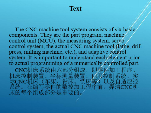
Machine Control Unit (MCU)机床控制装置
The machine control unit (MCU) is a microcomputer that stores the program and executes the commands into actions by the machine tool. The MCU consists of two main units: the Data Processing Unit (DPU) and the Control Loops Unit (CLU). 机床控制装置(MCU)是一台微型计算机,其中存 有加工程序,机床通过执行程序指令来完成各种操作 。MCU主要由数据处理装置(DPU)、回路控制装 置(CLU)组成。
DPU软件包括控制系统软件、算法软件、翻译软件、 插补算法及程序编辑等,其中翻译软件可将加工程序 转换为MCU可用格式,插补算法可使刀具平稳运动。
句中,that converts the part program into a usable format for the MCU系定语从句,修饰translation software; translation software为“翻译软件”之意。
中职电子技术个人教学计划范文
中职电子技术个人教学计划范文1.我将以培养学生的电子技术实践能力为教学目标。
I will take cultivating students' practical ability in electronic technology as the teaching objective.2.我计划引导学生学习电子器件的原理和应用。
I plan to guide students in learning the principles and applications of electronic devices.3.我会组织学生参与电子电路的实验操作。
I will organize students to participate in experimental operation of electronic circuits.4.我要让学生熟练使用各类电子仪器设备。
I want students to be proficient in using various electronic instruments and equipment.5.我会指导学生进行电子元件的焊接和组装。
I will guide students in soldering and assembling electronic components.6.我要求学生掌握常用电子软件的应用方法。
I require students to master the application methods of commonly used electronic software.7.我会帮助学生进行电子线路故障的分析和排除。
I will help students to analyze and eliminate electronic circuit faults.8.我会在教学中注重理论与实践相结合的教学方法。
I will pay attention to the teaching method ofintegrating theory with practice.9.我要激发学生对电子技术的兴趣和热情。
CY7C64215-56LFXC资料
3.2 The Digital System
The Digital System is composed of 4 digital enCoRe III blocks. Each block is an 8-bit resource that can be used alone or combined with other blocks to form 8, 16, 24, and 32-bit peripherals, which are called user module references.元器件交易网CY7 Nhomakorabea64215
enCoRe™ III Full Speed USB Controller
1.0 Features
• Powerful Harvard Architecture Processor — M8C Processor Speeds to 24 MHz — Two 8x8 Multiply, 32-bit Accumulate — 3.0 to 5.25V Operating Voltage — USB Temperature Range: 0°C to +70°C
QN8035pdf
players. It integrates FM receive functions, auto-seek and clear channel scan. Advanced digital architecture enables
superior receiver sensitivity and crystal clear audio.
Confidential Information contained herein is covered under Non-Disclosure Agreement (NDA).
Advance Technical Information. This is a product under development. Characteristics and specifications are subject to change without notice.
• Robust Operation • -250C to +850C operation • ESD protection on all input and output pads
• 1 KHz Tone Generator Inside
, ___________________________ Typical Applications ________________________
4
QQ: Control Interface Protocol .............................................................................................................................14
LH79520中文资料
LH75401/LH75411 Preliminary data sheet System-on-ChipDESCRIPTIONThe NXP BlueStreak LH75401/LH75411 family con-sists of two low-cost 16/32-bit System-on-Chip (SoC) devices.•LH75401 — contains the superset of features.•LH75411 — similar to LH75401, without CAN 2.0B.COMMON FEATURES•Highly Integrated System-on-Chip•ARM7TDMI-S™ Core•High Performance (84 MHz CPU Speed)–Internal PLL Driven or External Clock Driven–Crystal Oscillator/Internal PLL Can Operate with Input Frequency Range of 14 MHz to 20MHz •32kB On-chip SRAM–16kB Tightly Coupled Memory (TCM) SRAM–16kB Internal SRAM•Clock and Power Management–Low Power Modes: Standby, Sleep, Stop •Eight Channel, 10-bit Analog-to-Digital Converter •Integrated Touch Screen Controller•Serial interfaces–Two 16C550-type UARTs supporting baud rates up to 921,600 baud (requires crystal frequency of14.756 MHz).–One 82510-type UART supporting baud rates up to 3,225,600 baud (requires a system clock of70MHz).•Synchronous Serial Port–Motorola SPI™–National Semiconductor Microwire™–Texas Instruments SSI•Real-Time Clock (RTC)•Three Counter/Timers–Capture/Compare/PWM Compatibility–Watchdog Timer (WDT)•Low-Voltage Detector •JTAG Debug Interface and Boundary Scan •Single 3.3 V Supply• 5 V Tolerant Digital I/O–XTALIN and XTAL32IN inputs are 1.8 V ± 10%•144-pin LQFP Package•−40°C to +85°C Operating TemperatureUnique Features of the LH75401•Color and Grayscale Liquid Crystal Display (LCD) Controller–12-bit (4,096) Direct Mode Color, up to VGA–8-bit (256) Direct or Palettized Color, up to SVGA –4-bit (16) Direct Mode Color/Grayscale, up to XGA –12-bit Video Bus–Supports STN, TF T, HR-TF T, and AD-TF T Displays.•CAN Controller that supports CAN version 2.0B.Unique Features of the LH75411•Color and Grayscale LCD Controller (LCDC)–12-bit (4,096) Direct Mode Color, up to VGA–8-bit (256) Direct or Palettized Color, up to SVGA –4-bit (16) Direct Mode Color/Grayscale, up to XGA –12-bit Video Bus–Supports STN, TF T, HR-TF T, and AD-TF T Displays.元器件交易网Preliminary data sheet 1LH75401/LH75411System-on-Chip2Rev. 01— 16 July 2007Preliminary data sheetNXP SemiconductorsORDERING INFORMATIONTable 1.Ordering informationType number PackageVersionName DescriptionLH75401N0Q100C0LQFP144plastic low profile quad flat package; 144 leads;body 20 x 20 x 1.4 mmSOT486-1LH75411N0Q100C0LQFP144plastic low profile quad flat package; 144 leads;body 20 x 20 x 1.4 mmSOT486-1元器件交易网System-on-ChipLH75401/LH75411Preliminary data sheet Rev. 01 — 16 July 2007 3NXP SemiconductorsLH75401 BLOCK DIAGRAMFigure 1.LH75401 Block Diagram元器件交易网LH75401/LH75411System-on-Chip4Rev. 01— 16 July 2007Preliminary data sheetNXP SemiconductorsLH75411 BLOCK DIAGRAMFigure 2.LH75411 Block Diagram元器件交易网System-on-ChipLH75401/LH75411Preliminary data sheet Rev. 01 — 16 July 2007 5NXP SemiconductorsPIN CONFIGURATIONFigure 3.LH75401/LH75411 pin configuration元器件交易网LH75401/LH75411System-on-Chip6Rev. 01— 16 July 2007Preliminary data sheetNXP SemiconductorsLH75401 Numerical Pin ListingTable 2.LH75401 Numerical Pin ListPIN NO.FUNCTION AT RESETFUNCTION2FUNCTION 3FUNCTION TYPE OUTPUTDRIVEBUFFERTYPE BEHAVIOR DURINGRESETNOTES 1PA7D15I/O 8 mA Bidirectional Pull-up 12PA6D14I/O 8 mA Bidirectional Pull-up 13VDD Power None 4PA5D13I/O 8 mA Bidirectional Pull-up 15PA4D12I/O 8 mA Bidirectional Pull-up 16PA3D11I/O 8 mA Bidirectional Pull-up 17PA2D10I/O 8 mA Bidirectional Pull-up 18VSS Ground None 9PA1D9I/O 8 mA Bidirectional Pull-up 110PA0D8I/O 8 mA Bidirectional Pull-up 111VDDC Power None 12D7I/O 8 mA Bidirectional Pull-up 13D6I/O 8 mA Bidirectional Pull-up 14VSSC Ground None 15D5I/O 8 mA Bidirectional Pull-up 16D4I/O 8 mA Bidirectional Pull-up 17VDD Power None 18D3I/O 8 mA Bidirectional Pull-up 19D2I/O 8 mA Bidirectional Pull-up 20D1I/O 8 mA Bidirectional Pull-up 21D0I/O8 mA Bidirectional Pull-up 22nWE 8 mA Output HIGH 323nOE 8 mA Output HIGH 324PB5nWAIT 8 mA Bidirectional Pull-up 1, 325PB4nBLE18 mA Bidirectional Pull-up 1, 326VSS GroundNone 27PB3nBLE08 mA Bidirectional Pull-up 1, 328PB2nCS38 mA Bidirectional Pull-up 1, 329PB1nCS28 mA Bidirectional Pull-up 1, 330PB0nCS18 mA Bidirectional Pull-up 1, 331nCS08 mA Output Pull-up 332PC7A238 mA Bidirectional Pull-down 133PC6A228 mA BidirectionalPull-down134VDD PowerNone 35PC5A218 mA Bidirectional Pull-down 136PC4A208 mA Bidirectional Pull-down 137PC3A198 mA Bidirectional Pull-down 138PC2A188 mABidirectionalPull-down1元器件交易网System-on-ChipLH75401/LH75411Preliminary data sheet Rev. 01 — 16 July 2007 7NXP Semiconductors39PC1A178 mA Bidirectional Pull-down 140PC0A168 mA BidirectionalPull-down141VSS Ground None 42VDD PowerNone 43A158 mA Output LOW 44A148 mA Output LOW 45A138 mA Output LOW 46A128 mA Output LOW 47A118 mA OutputLOW48VSS GroundNone 49A108 mA Output LOW 50A98 mA Output LOW 51A88 mA Output LOW 52A78 mA Output LOW 53A68 mA OutputLOW54VDD Power None 55A58 mA Output LOW 56A48 mA Output LOW 57A38 mA Output LOW 58A28 mA OutputLOW59VSS Ground None 60A18 mA Output LOW 61A08 mA Output LOW 62nRESETIN None Input Pull-up 2, 363TEST2None Input Pull-up 264TEST1None Input Pull-up 265TMS None Input Pull-up266RTCK 8 mA Output 67TCK None Input 68TDI None Input Pull-up269TDO 4 mA Output 70LINREGEN None Input 571nRESETOUT8 mA Output 372PD6INT6DREQ 6 mA Bidirectional Pull-down173PD5INT5DACK 6 mA Bidirectional 1, 274PD4INT4UARTRX18 mA BidirectionalPull-up 175VDDC Power None 76PD3INT3UARTTX18 mA Bidirectional Pull-up 177PD2INT2 2 mA Bidirectional Pull-up178PD1INT1 6 mA Bidirectional 1, 279PD0INT02 mA Bidirectional180VSSCGroundNoneTable 2.LH75401 Numerical Pin List (Cont’d)PIN NO.FUNCTION AT RESETFUNCTION2FUNCTION 3FUNCTION TYPE OUTPUTDRIVEBUFFERTYPE BEHAVIOR DURINGRESETNOTES 元器件交易网LH75401/LH75411System-on-Chip8Rev. 01— 16 July 2007Preliminary data sheetNXP Semiconductors81nPOR None Input Pull-up2, 382XTAL32IN None Input 483XTAL32OUT None Output84VSSA_PLL Ground None 85VDDA_PLL PowerNone 86XTALIN None Input 487XTALOUT None Output88VSSA_ADC Ground None 89AN3 (LR/Y-)PJ7None Input 90AN4 (Wiper)PJ6None Input 91AN9PJ5None Input 92AN2 (LL/Y+)PJ4None Input 93AN8PJ3None Input 94AN1 (UR/X-)PJ2None Input 95AN6PJ1None Input 96AN0 (UL/X+)PJ0None Input 97VDDA_ADCPower None 98VDD Power None 99PE7SSPFRM 4 mA Bidirectional Pull-up 1100PE6SSPCLK 4 mA Bidirectional Pull-down 1101PE5SSPRX 4 mA Bidirectional Pull-up 1102PE4SSPTX 4 mA Bidirectional Pull-down 1103PE3CANTX UARTTX08 mA Bidirectional Pull-up 1104PE2CANRX UARTRX02 mA Bidirectional Pull-up 1105PE1UARTTX24 mA BidirectionalPull-up1106VSS GroundNone 107PE0UARTRX2 4 mA Bidirectional Pull-up1108PF6CTCAP2B CTCMP2B 4 mA Bidirectional 2109PF5CTCAP2A CTCMP2A 4 mA Bidirectional 110PF4CTCAP1B CACMP1B 4 mA Bidirectional 2111PF3CTCAP1ACTCMP1A4 mA Bidirectional112VDD PowerNone 113PF2CTCAP0E 4 mA Bidirectional 2114PF1CTCAP0D 4 mA Bidirectional 115PF0CTCAP0C 4 mA Bidirectional 2116PG7CTCAP0B CTCMP0B 4 mA Bidirectional 117PG6CTCAP0A CTCMP0A4 mA Bidirectional 2118PG5CTCLK4 mA Bidirectional119VSS GroundNone 120PG4LCDVEEEN LCDMOD8 mA Bidirectional 121PG3LCDVDDEN 8 mA Bidirectional 122PG2LCDDSPLENLCDREV 8 mABidirectional Table 2.LH75401 Numerical Pin List (Cont’d)PIN NO.FUNCTION AT RESET FUNCTION2FUNCTION 3FUNCTION TYPE OUTPUTDRIVEBUFFERTYPE BEHAVIOR DURINGRESETNOTES 元器件交易网System-on-ChipLH75401/LH75411Preliminary data sheet Rev. 01 — 16 July 2007 9NXP SemiconductorsNOTES:1.Signal is selectable as pull-up, pull-down, or no pull-up/pull-down via the I/O Configuration peripheral.2.CMOS Schmitt trigger input.3.Signals preceded with ‘n’ are active LOW.4.Crystal Oscillator Inputs should be driven to 1.8 V ±10% (MAX.)5.LINREGEN activation requires a 0 Ω pull-up to VDD.123PG1LCDCLS 8 mA Bidirectional 124PG0LCDPS 8 mA Bidirectional 125PH7LCDDCLK8 mABidirectional126VDD Power None 127VSS GroundNone 128PH6LCDLP LCDHRLP 8 mA Bidirectional 129PH5LCDFP LCDSPS 8 mA Bidirectional 130PH4LCDEN LCDSPL8 mA Bidirectional 131PH3LCDVD118 mA Bidirectional 132PH2LCDVD108 mA Bidirectional 133PH1LCDVD98 mABidirectional 134VDD PowerNone 135PH0LCDVD88 mA Bidirectional 136PI7LCDVD78 mA Bidirectional 137PI6LCDVD68 mA Bidirectional 138PI5LCDVD58 mA Bidirectional 139PI4LCDVD48 mABidirectional 140VSS GroundNone 141PI3LCDVD38 mA Bidirectional 142PI2LCDVD28 mA Bidirectional 143PI1LCDVD18 mA Bidirectional 144PI0LCDVD08 mABidirectionalTable 2.LH75401 Numerical Pin List (Cont’d)PIN NO.FUNCTION AT RESETFUNCTION2FUNCTION 3FUNCTION TYPE OUTPUTDRIVEBUFFERTYPE BEHAVIOR DURINGRESETNOTESLH75401/LH75411System-on-Chip10Rev. 01 — 16 July 2007Preliminary data sheetNXP SemiconductorsLH75401 Signal DescriptionsTable 3.LH75401 Signal DescriptionsPIN NO.SIGNAL NAMETYPEDESCRIPTIONNOTESMEMORY INTERFACE (MI)1245679101213151618192021D[15:0]Input/Output Data Input/Output Signals 122nWE Output Static Memory Controller Write Enable 223nOE Output Static Memory Controller Output Enable 224nWAIT Input Static Memory Controller External Wait Control 1, 225nBLE1Output Static Memory Controller Byte Lane Strobe 1, 227nBLE0Output Static Memory Controller Byte Lane Strobe 1, 228nCS3Output Static Memory Controller Chip Select 1, 229nCS2Output Static Memory Controller Chip Select 1, 230nCS1Output Static Memory Controller Chip Select 1, 231nCS0OutputStatic Memory Controller Chip Select23233 35363738394043444546474950515253555657586061A[23:0]Output Address Signals 1DMA CONTROLLER (DMAC)72DREQ Input DMA Request 173DACKOutputDMA Acknowledge1PIN NO.SIGNAL NAME TYPE DESCRIPTION NOTESCOLOR LCD CONTROLLER (CLCDC)120LCDMOD Output Signal Used by the Row Driver (AD-TFT, HR-TFT only)1 120LCDVEEEN Output Analog Supply Enable (AC Bias SIgnal)1 121LCDVDDEN Output Digital Supply Enable1 122LCDDSPLEN Output LCD Panel Power Enable1 122LCDREV Output Reverse Signal (AD-TFT, HR-TFT only)1 123LCDCLS Output Clock to the Row Drivers (AD-TFT, HR-TFT only)1 124LCDPS Output Power Save (AD-TFT, HR-TFT only)1 125LCDDCLK Output LCD Panel Clock1 128LCDLP Output Line Synchronization Pulse (STN), Horizontal Synchronization Pulse (TFT)1 128LCDHRLP Output Latch Pulse (AD-TFT, HR-TFT only)1 129LCDFP Output Frame Pulse (STN), Vertical Synchronization Pulse (TFT)1 129LCDSPS Output Row Driver Counter Reset Signal (AD-TFT, HR-TFT only)1 130LCDEN Output LCD Data Enable1 130LCDSPL Output Start Pulse Left (AD-TFT, HR-TFT only)1 131132133135136137LCDVD[11:0]Output LCD Panel Data bus1 138139141142143144SYNCHRONOUS SERIAL PORT (SSP)99SSPFRM Output SSP Serial Frame1 100SSPCLK Output SSP Clock1 101SSPRX Input SSP RXD1 102SSPTX Output SSP TXD1UART0 (U0)103UARTTX0Output UART0 Transmitted Serial Data Output1 104UARTRX0Input UART0 Received Serial Data Input1UART1 (U1)74UARTRX1Input UART1 Received Serial Data Input1 76UARTTX1Output UART1 Transmitted Serial Data Output1UART2 (U2)105UARTTX2Output UART2 Transmitted Serial Data Output1 107UARTRX2Input UART2 Received Serial Data Input1CONTROLLER AREA NETWORK (CAN)103CANTX Output CAN Transmitted Serial Data Output1 104CANRX Input CAN Received Serial Data Input1ANALOG-TO-DIGITAL CONVERTER (ADC)89 90 91 92 93 94 95 96AN3 (LR/Y-)AN4 (Wiper)AN9AN2 (LL/Y+)AN8AN1 (UR/X-)AN6AN0 (UL/X+)Input ADC Inputs1TIMER 0117116115114113CTCAP0[A:E]Input Timer 0 Capture Inputs1117116CTCMP0[A:B]Output Timer 0 Compare Outputs1 118CTCLK Input Common External Clock1TIMER 1111110CTCAP1[A:B]Input Timer 1 Capture Inputs1 111110CTCMP1[A:B]Output Timer 1 Compare Outputs1 118CTCLK Input Common External Clock1TIMER 2109108CTCAP2[A:B]Input Timer 2 Capture Inputs1 109108CTCMP2[A:B]Input Timer 2 Compare Outputs1 118CTCLK Input Common External Clock1GENERAL PURPOSE INPUT/OUTPUT (GPIO)1 2 4 5 6 7 9 10PA7PA6PA5PA4PA3PA2PA1PA0Input/Output General Purpose I/O Signals - Port A124 25 27 28 29 30PB5PB4PB3PB2PB1PB0Input/Output General Purpose I/O Signals - Port B132 33 35 36 37 38 39 40PC7PC6PC5PC4PC3PC2PC1PC0Input/Output General Purpose I/O Signals - Port C1PIN NO.SIGNAL NAME TYPE DESCRIPTION NOTES72 73 74 76 77 78 79PD6PD5PD4PD3PD2PD1PD0Input/Output General Purpose I/O Signals - Port D189 90 91 92 93 94 95 96PJ7PJ6PJ5PJ4PJ3PJ2PJ1PJ0Input General Purpose I/O Signals - Port J199 100 101 102 103 104 105 107PE7PE6PE5PE4PE3PE2PE1PE0Input/Output General Purpose I/O Signals - Port E1108 109 110 111 113 114 115PF6PF5PF4PF3PF2PF1PF0Input/Output General Purpose I/O Signals - Port F1116 117 118 120 121 122 123 124PG7PG6PG5PG4PG3PG2PG1PG0Input/Output General Purpose I/O Signals - Port G1125 128 129 130 131 132 133 135PH7PH6PH5PH4PH3PH2PH1PH0Input/Output General Purpose I/O Signals - Port H1136 137 138 139 141 142 143 144PI7PI6PI5PI4PI3PI2PI1PI0Input/Output General Purpose I/O Signals - Port I1 RESET, CLOCK, AND POWER CONTROLLER (RCPC)62nRESETIN Input User Reset Input2 71nRESETOUT Output System Reset Output2 72INT6Input External Interrupt Input 61 PIN NO.SIGNAL NAME TYPE DESCRIPTION NOTESNOTES:1.These pin numbers have multiplexed functions.2.Signals preceded with ‘n’ are active LOW.73INT5Input External Interrupt Input 5174INT4Input External Interrupt Input 4176INT3Input External Interrupt Input 3177INT2Input External Interrupt Input 2178INT1Input External Interrupt Input 1179INT0Input External Interrupt Input 0181nPOR Input Power-on Reset Input282XTAL32IN Input 32.768 kHz Crystal Clock Input 83XTAL32OUT Output 32.768 kHz Crystal Clock Output 86XTALIN Input Crystal Clock Input 87XTALOUT Output Crystal Clock OutputTEST INTERFACE63TEST2Input Test Mode Pin 264TEST1Input Test Mode Pin 165TMS Input JTAG Test Mode Select Input 66RTCK Output Returned JTAG Test Clock Output 67TCK Input JTAG Test Clock Input 68TDI Input JTAG Test Serial Data Input 69TDOOutputJTAG Test Data Serial OutputPOWER AND GROUND (GND)31734425498112126134VDD Power I/O Ring VDD826414859106119127140VSS Power I/O Ring VSS1175VDDC Power Core VDD supply (Output if Linear Regulator Enabled, Otherwise Input)1480VSSC Power Core VSS70LINREGEN Input Linear Regulator Enable 84VSSA_PLL Power PLL Analog VSS 85VDDA_PLL Power PLL Analog VDD Supply 88VSSA_ADC Power A-to-D converter Analog VSS 97VDDA_ADCPowerA-to-D converter Analog VDD SupplyPIN NO.SIGNAL NAME TYPE DESCRIPTIONNOTESLH75411 Numerical Pin ListingTable 4.LH75411 Numerical Pin ListPIN NO.FUNCTIONAT RESETFUNCTION2FUNCTION3FUNCTIONTYPEOUTPUTDRIVEBUFFERTYPEBEHAVIOR DURINGRESET NOTES1PA7D15I/O8 mA Bidirectional Pull-up1 2PA6D14I/O8 mA Bidirectional Pull-up1 3VDD Power None4PA5D13I/O8 mA Bidirectional Pull-up1 5PA4D12I/O8 mA Bidirectional Pull-up1 6PA3D11I/O8 mA Bidirectional Pull-up1 7PA2D10I/O8 mA Bidirectional Pull-up1 8VSS Ground None9PA1D9I/O8 mA Bidirectional Pull-up1 10PA0D8I/O8 mA Bidirectional Pull-up1 11VDDC Power None12D7I/O8 mA Bidirectional Pull-up13D6I/O8 mA Bidirectional Pull-up14VSSC Ground None15D5I/O8 mA Bidirectional Pull-up16D4I/O8 mA Bidirectional Pull-up17VDD Power None18D3I/O8 mA Bidirectional Pull-up19D2I/O8 mA Bidirectional Pull-up20D1I/O8 mA Bidirectional Pull-up21D0I/O8 mA Bidirectional Pull-up22nWE8 mA Output HIGH3 23nOE8 mA Output HIGH3 24PB5nWAIT8 mA Bidirectional Pull-up1, 3 25PB4nBLE18 mA Bidirectional Pull-up1, 3 26VSS Ground None27PB3nBLE08 mA Bidirectional Pull-up1, 3 28PB2nCS38 mA Bidirectional Pull-up1, 3 29PB1nCS28 mA Bidirectional Pull-up1, 3 30PB0nCS18 mA Bidirectional Pull-up1, 3 31nCS08 mA Output Pull-up3 32PC7A238 mA Bidirectional Pull-down1 33PC6A228 mA Bidirectional Pull-down1 34VDD Power None35PC5A218 mA Bidirectional Pull-down1 36PC4A208 mA Bidirectional Pull-down1 37PC3A198 mA Bidirectional Pull-down1 38PC2A188 mA Bidirectional Pull-down1 39PC1A178 mA Bidirectional Pull-down1 40PC0A168 mA Bidirectional Pull-down1 41VSS Ground None42VDD PowerNone 43A158 mA Output LOW 44A148 mA Output LOW 45A138 mA Output LOW 46A128 mA Output LOW 47A118 mA OutputLOW48VSS GroundNone 49A108 mA Output LOW 50A98 mA Output LOW 51A88 mA Output LOW 52A78 mA Output LOW 53A68 mA OutputLOW54VDD Power None 55A58 mA Output LOW 56A48 mA Output LOW 57A38 mA Output LOW 58A28 mA OutputLOW59VSS Ground None 60A18 mA Output LOW 61A08 mA Output LOW 62nRESETIN None Input Pull-up 2, 363TEST2None Input Pull-up 264TEST1None Input Pull-up 265TMS None Input Pull-up266RTCK 8 mA Output 67TCK None Input 68TDI None Input Pull-up269TDO 4 mA Output 70LINREGEN None Input 571nRESETOUT8 mA Output 372PD6INT6DREQ 6 mA Bidirectional Pull-down173PD5INT5DACK 6 mA Bidirectional 1, 274PD4INT4UARTRX18 mA BidirectionalPull-up 175VDDC Power None 76PD3INT3UARTTX18 mA Bidirectional Pull-up 177PD2INT2 2 mA Bidirectional Pull-up178PD1INT1 6 mA Bidirectional 1, 279PD0INT02 mA Bidirectional180VSSC GroundNone 81nPOR None Input Pull-up2, 382XTAL32IN None Input 483XTAL32OUTNoneOutputPIN NO.FUNCTION AT RESETFUNCTION2FUNCTION 3FUNCTION TYPE OUTPUTDRIVEBUFFERTYPEBEHAVIOR DURINGRESETNOTES84VSSA_PLL Ground None 85VDDA_PLL PowerNone 86XTALIN None Input 487XTALOUT None Output88VSSA_ADC GroundNone 89AN3 (LR/Y-)PJ7None Input 90AN4 (Wiper)PJ6None Input 91AN9PJ5None Input 92AN2 (LL/Y+)PJ4None Input 93AN8PJ3None Input 94AN1 (UR/X-)PJ2None Input 95AN6PJ1None Input 96AN0 (UL/X+)PJ0None Input 97VDDA_ADCPower None 98VDD Power None 99PE7SSPFRM 4 mA Bidirectional Pull-up 1100PE6SSPCLK 4 mA Bidirectional Pull-down 1101PE5SSPRX 4 mA Bidirectional Pull-up 1102PE4SSPTX 4 mA Bidirectional Pull-down 1103PE3UARTTX08 mA Bidirectional Pull-up 1104PE2UARTRX0 2 mA Bidirectional Pull-up 1105PE1UARTTX24 mA BidirectionalPull-up1106VSS GroundNone 107PE0UARTRX2 4 mA Bidirectional Pull-up1108PF6CTCAP2B CTCMP2B 4 mA Bidirectional 2109PF5CTCAP2A CTCMP2A 4 mA Bidirectional 110PF4CTCAP1B CACMP1B 4 mA Bidirectional 2111PF3CTCAP1ACTCMP1A4 mA Bidirectional112VDD PowerNone 113PF2CTCAP0E 4 mA Bidirectional 2114PF1CTCAP0D 4 mA Bidirectional 115PF0CTCAP0C 4 mA Bidirectional 2116PG7CTCAP0B CTCMP0B 4 mA Bidirectional 117PG6CTCAP0A CTCMP0A4 mA Bidirectional 2118PG5CTCLK4 mA Bidirectional119VSS GroundNone 120PG4LCDVEEEN LCDMOD8 mA Bidirectional 121PG3LCDVDDEN 8 mA Bidirectional 122PG2LCDDSPLEN LCDREV 8 mA Bidirectional 123PG1LCDCLS 8 mA Bidirectional 124PG0LCDPS 8 mA Bidirectional 125PH7LCDDCLK8 mABidirectional PIN NO.FUNCTION AT RESET FUNCTION2FUNCTION 3FUNCTION TYPE OUTPUTDRIVEBUFFERTYPEBEHAVIOR DURINGRESETNOTESNOTES:1.Signal is selectable as pull-up, pull-down, or no pull-up/pull-down via the I/O Configuration peripheral.2.CMOS Schmitt trigger input.3.Signals preceded with ‘n’ are active LOW.4.Crystal Oscillator Inputs should be driven to 1.8 V ±10% (MAX.)5.LINREGEN activation requires a 0 Ω pull-up to VDD.126VDD Power None 127VSS GroundNone 128PH6LCDLP LCDHRLP 8 mA Bidirectional 129PH5LCDFP LCDSPS 8 mA Bidirectional 130PH4LCDEN LCDSPL8 mA Bidirectional 131PH3LCDVD118 mA Bidirectional 132PH2LCDVD108 mA Bidirectional 133PH1LCDVD98 mABidirectional 134VDD PowerNone 135PH0LCDVD88 mA Bidirectional 136PI7LCDVD78 mA Bidirectional 137PI6LCDVD68 mA Bidirectional 138PI5LCDVD58 mA Bidirectional 139PI4LCDVD48 mABidirectional 140VSS GroundNone 141PI3LCDVD38 mA Bidirectional 142PI2LCDVD28 mA Bidirectional 143PI1LCDVD18 mA Bidirectional 144PI0LCDVD08 mABidirectionalPIN NO.FUNCTION AT RESETFUNCTION2FUNCTION 3FUNCTION TYPE OUTPUTDRIVEBUFFERTYPE BEHAVIOR DURINGRESETNOTESLH75411 Signal DescriptionsTable 5.LH75411 Signal DescriptionsPIN NO.SIGNAL NAME TYPE DESCRIPTION NOTESMEMORY INTERFACE (MI)124567910D[15:0]Input/Output Data Input/Output Signals1 121315161819202122nWE Output Static Memory Controller Write Enable2 23nOE Output Static Memory Controller Output Enable2 24nWAIT Input Static Memory Controller External Wait Control1, 2 25nBLE1Output Static Memory Controller Byte Lane Strobe1, 2 27nBLE0Output Static Memory Controller Byte Lane Strobe1, 2 28nCS3Output Static Memory Controller Chip Select1, 2 29nCS2Output Static Memory Controller Chip Select1, 2 30nCS1Output Static Memory Controller Chip Select1, 2 31nCS0Output Static Memory Controller Chip Select2 323335363738394043444546A[23:0]Output Address Signals1 474950515253555657586061DMA CONTROLLER (DMAC)72DREQ Input DMA Request1 73DACK Output DMA Acknowledge1COLOR LCD CONTROLLER (CLCDC)120LCDMOD Output Signal Used by the Row Driver (AD-TFT, HR-TFT only)1 120LCDVEEEN Output Analog Supply Enable (AC Bias SIgnal)1 121LCDVDDEN Output Digital Supply Enable1 122LCDDSPLEN Output LCD Panel Power Enable1 122LCDREV Output Reverse Signal (AD-TFT, HR-TFT only)1 123LCDCLS Output Clock to the Row Drivers (AD-TFT, HR-TFT only)1 124LCDPS Output Power Save (AD-TFT, HR-TFT only)1 125LCDDCLK Output LCD Panel Clock1 128LCDLP Output Line Synchronization Pulse (STN), Horizontal Synchronization Pulse (TFT)1 128LCDHRLP Output Latch Pulse (AD-TFT, HR-TFT only)1 129LCDFP Output Frame Pulse (STN), Vertical Synchronization Pulse (TFT)1 129LCDSPS Output Row Driver Counter Reset Signal (AD-TFT, HR-TFT only)1 130LCDEN Output LCD Data Enable1 130LCDSPL Output Start Pulse Left (AD-TFT, HR-TFT only)1 131132133135136137138139141142143144LCDVD[11:0]Output LCD Panel Data bus1SYNCHRONOUS SERIAL PORT (SSP)99SSPFRM Output SSP Serial Frame1 100SSPCLK Output SSP Clock1 101SSPRX Input SSP RXD1 102SSPTX Output SSP TXD1UART0 (U0)104UARTRX0Input UART0 Received Serial Data Input1 103UARTTX0Output UART0 Transmitted Serial Data Output1UART1 (U1)74UARTRX1Input UART1 Received Serial Data Input1 76UARTTX1Output UART1 Transmitted Serial Data Output1UART2 (U2)105UARTTX2Output UART2 Transmitted Serial Data Output1 107UARTRX2Input UART2 Received Serial Data Input1ANALOG-TO-DIGITAL CONVERTER (ADC)89 90 91 92 93 94 95 96AN3 (LR/Y-)AN4 (Wiper)AN9AN2 (LL/Y+)AN8AN1 (UR/X-)AN6AN0 (UL/X+)Input ADC Inputs1Table 5.LH75411 Signal Descriptions (Cont’d)PIN NO.SIGNAL NAME TYPE DESCRIPTION NOTESTIMER 0117116115114113CTCAP0[A:E]Input Timer 0 Capture Inputs1117116CTCMP0[A:B]Output Timer 0 Compare Outputs1 118CTCLK Input Common External Clock1TIMER 1111110CTCAP1[A:B]Input Timer 1 Capture Inputs1 111110CTCMP1[A:B]Output Timer 1 Compare Outputs1 118CTCLK Input Common External Clock1TIMER 2109108CTCAP2[A:B]Input Timer 2 Capture Inputs1 109108CTCMP2[A:B]Input Timer 2 Compare Outputs1 118CTCLK Input Common External Clock1GENERAL PURPOSE INPUT/OUTPUT (GPIO)1 2 4 5 6 7 9 10PA7PA6PA5PA4PA3PA2PA1PA0Input/Output General Purpose I/O Signals - Port A124 25 27 28 29 30PB5PB4PB3PB2PB1PB0Input/Output General Purpose I/O Signals - Port B132 33 35 36 37 38 39 40PC7PC6PC5PC4PC3PC2PC1PC0Input/Output General Purpose I/O Signals - Port C172 73 74 76 77 78 79PD6PD5PD4PD3PD2PD1PD0Input/Output General Purpose I/O Signals - Port D1PIN NO.SIGNAL NAME TYPE DESCRIPTION NOTES89 90 91 92 93 94 95 96PJ7PJ6PJ5PJ4PJ3PJ2PJ1PJ0Input General Purpose I/O Signals - Port J199 100 101 102 103 104 105 107PE7PE6PE5PE4PE3PE2PE1PE0Input/Output General Purpose I/O Signals - Port E1108 109 110 111 113 114 115PF6PF5PF4PF3PF2PF1PF0Input/Output General Purpose I/O Signals - Port F1116 117 118 120 121 122 123 124PG7PG6PG5PG4PG3PG2PG1PG0Input/Output General Purpose I/O Signals - Port G1125 128 129 130 131 132 133 135PH7PH6PH5PH4PH3PH2PH1PH0Input/Output General Purpose I/O Signals - Port H1136 137 138 139 141 142 143 144PI7PI6PI5PI4PI3PI2PI1PI0Input/Output General Purpose I/O Signals - Port I1 RESET, CLOCK, AND POWER CONTROLLER (RCPC)62nRESETIN Input User Reset Input2 71nRESETOUT Output System Reset Output2 72INT6Input External Interrupt Input 61 73INT5Input External Interrupt Input 51 74INT4Input External Interrupt Input 41 76INT3Input External Interrupt Input 31 77INT2Input External Interrupt Input 21 78INT1Input External Interrupt Input 11 79INT0Input External Interrupt Input 01 PIN NO.SIGNAL NAME TYPE DESCRIPTION NOTESNOTES:1.These pin numbers have multiplexed functions.2.Signals preceded with ‘n’ are active LOW.81nPOR Input Power-on Reset Input282XTAL32IN Input 32.768 kHz Crystal Clock Input 83XTAL32OUT Output 32.768 kHz Crystal Clock Output 86XTALIN Input Crystal Clock Input 87XTALOUT Output Crystal Clock OutputTEST INTERFACE63TEST2Input Test Mode Pin 264TEST1Input Test Mode Pin 165TMS Input JTAG Test Mode Select Input 66RTCK Output Returned JTAG Test Clock Output 67TCK Input JTAG Test Clock Input 68TDI Input JTAG Test Serial Data Input 69TDOOutputJTAG Test Data Serial OutputPOWER AND GROUND (GND)31734425498112126134VDD Power I/O Ring VDD826414859106119127140VSS Power I/O Ring VSS1175VDDC Power Core VDD supply (Output if Linear Regulator Enabled, Otherwise Input)1480VSSC Power Core VSS70LINREGEN Input Linear Regulator Enable 84VSSA_PLL Power PLL Analog VSS 85VDDA_PLL Power PLL Analog VDD Supply 88VSSA_ADC Power A-to-D converter Analog VSS 97VDDA_ADCPowerA-to-D converter Analog VDD SupplyPIN NO.SIGNAL NAME TYPE DESCRIPTIONNOTESFUNCTIONAL OVERVIEWARM7TDMI-S ProcessorThe LH75401/LH75411 microcontrollers feature the ARM7TDMI-S core with an Advanced High-Performance Bus (AHB) 2.0 interface. The ARM7TDMI-S is a 16/32-bit embedded RISC processor and a member of the ARM7 Thumb family of processors. For more information, visit the ARM Web site at .Bus ArchitectureThe LH75401/LH75411 microcontrollers use the ARM Advanced Microcontroller Bus Architecture (AMBA) 2.0 internal bus protocol. Three AHB masters control access to external memory and on-chip peripherals:•The ARM processor fetches instructions and trans-fers data•The Direct Memory Access Controller (DMAC) trans-fers from memory to memory, from peripheral to memory, and from memory to peripheral•The LCDC refreshes an LCD panel with data from the external memory or from internal memory if the frame buffer is 16kB or less.The ARM7TDMI-S processor is the default bus mas-ter. An Advanced Peripheral Bus (APB) bridge is pro-vided to access to the various APB peripherals. Generally, APB peripherals are serviced by the ARM core. However, if they are DMA-enabled, they are also serviced by the DMAC to increase system performance while the ARM core runs from local internal memory.Power SuppliesFive-Volt-tolerant 3.3 V I/Os are employed. The LH75401/LH75411 microcontrollers require a single 3.3V supply. The core logic requires 1.8 V, supplied by an on-chip linear regulator. Core logic power may also be supplied externally to achieve higher system speeds. See the Electrical Specifications.Clock SourcesThe LH75401/LH75411 microcontrollers may use two crystal oscillators, or an externally supplied clock. There are two clock trees:•One clock tree drives an internal Phase Lock Loop (PLL) and the three UARTs. It supports a crystal oscillator frequency range from 14 MHz to 20 MHz. •The other is a 32.768 kHz oscillator that generates a 1Hz clock for the RTC. (Use of the 32.768 kHz crys-tal for the Real Time Clock is optional. If not using the crystal, tie XTAL32IN to VSS and allow XTAL32OUT to float.)The 14-to-20 MHz crystal oscillator drives the UART clocks, so an oscillator frequency of 14.7456 MHz is rec-ommended to achieve modem baud rates.The PLL may be bypassed and an external clock supplied at XTALIN; the SoC will operate to DC with the PLL disabled. When doing so, allow XTALOUT to float. The input clock with the PLL bypassed will be twice the desired system operating frequency, and care must be taken not to exceed the maximum input clock voltage. Maximum values for system speeds and input voltages are given in the Electrical Specifications.Figure 4.LH75401 System Application Example。
- 1、下载文档前请自行甄别文档内容的完整性,平台不提供额外的编辑、内容补充、找答案等附加服务。
- 2、"仅部分预览"的文档,不可在线预览部分如存在完整性等问题,可反馈申请退款(可完整预览的文档不适用该条件!)。
- 3、如文档侵犯您的权益,请联系客服反馈,我们会尽快为您处理(人工客服工作时间:9:00-18:30)。
Autonomously Proficient CNC Controller for High-Performance Machine Tools Based on an Open Architecture Concept
Kazuo Yamazaki (2)l, Yoshimaro Hanakiz, Masahiko Mori3, Kazusaka Tezuka4 l IMS Mechatronics Laboratory, University of California, Davis, USA ZOkuma Corporation, Oguchicho, Niwagun, Aichi, Japan 3Mori Selki Co., Ltd., Yamatokoriyama, Nara, Japan jMitutoyo Corporation, Takatsuku, Kawasakishi, Kanagawa, Japan Received on January 6, 1997
Abstract
The paper deals with the new controller for the high performance CNC machine tools. The controller pro- posed is referred to as “TRUE-CNC.” “TRUE” means Transparent, Transportable and Transplantable, Re- vivable, User-reconfigurable, and Evolving. TRUE-CNC allows the operator to achieve the maximum pro- ductivity and highest possible quality of the machined parts in a given environment with autonomous cap- turing of the machining operation proficiency. The TRUE-CNC controller provides intelligent functions for less-skilled operator to run the high performance machine tools as if a skilled operator does. The concept
and design aspects of the system architecture and the algorithms for functions developed for the TRUE- CNC are described in the paper.
Keywords : Intelligent CNC, Open CNC, Automatic Machining
1. Introduction The recent evolution of CNC machine tool systems points to achieving simultaneously higher accuracy and higher productivity. The principle of the evolution is to realize the
light duty machining under the high speed motion of the mechanism with highly repeatable accuracy. [l] Recent research works have contributed to the enhancement of the component of technologies for the high speed machine tools. [2], [3] However, the operation of high speed ma- chine tool with full utilization of the performance in a given environment (an available set of operators, tools, jigs and fixtures, etc.) is a problem for the end user of the machine because the operation usually requires the specific know- how and skill which is different from those of the conven- tional machining method (ordinary speed with relatively heavy duty cutting). In order to solve the current problem, an autonomously proficient CNC controller and the control- centered infrastructure was proposed as a feasible solu- tion to enhance the utilization of the advanced CNC ma- chine tool systems. The whole architecture of the infra- structure is referred to as “TRUE-CNC”. In TRUE-CNC, the CNC controller plays an important role not only to in- telligently control the machine tool motion and the ma- chining process but also to actively acquire all kinds of useful information available in the control and related re- sources to circulate and reuse them in the infrastructure with an appropriate interpretation. Fortunately, the re- cently-proposed technology of “Open Architecture CNC Controller“ is suitable for implementing TRUE-CNC sys- tem. Although there were active research done with the focus on how to design and construct the Open Architec- ture Controller so far [4], few research results were pre- sented regarding to what kind of specific functions should be implemented into the Open Architecture Controller by machine tool builders and end-users. The paper de- scribes TRUE-CNC as a good example of what can be done on the Open Architecture Controller. 2. ConceDtual Architecture of the TRUE-CNC Con- troller TRUE-CNC is named after the following conceptual fea- tures: The system software should be “Transparent”, “Transportable”, and “Transplantable”. “Transparent” means that the system architecture is transparent to the machine tool builder or to the end- user. “lransportable” means that any part of the control software can be ported to any remote site’ such as a stand alone personal computer, etc.. “Transplantable” - means that the control software can
be implemented to the upgrade-compatible. The machine tool system with the outdated software and hardware should be “Revivable” by replacing a part of controller with newly emerging elements. The functions of the controller should be ‘‘User re- configurable” to autonomously customize the con- troller based on specific needs, and The overall system should always be “Evolving” during the system life.
Reauirements for the Svstem Desiun of TRUE-
- CNC
Active use of the caotured machinina know-how: The information stored in the machining know-how data- base should efficiently be utilized for future autono- mous machining operation. Active checkina and refreshina of the resource and caotured know-how: The information stored in the database should always be checked if the data