光敏电阻LG34系列规格书
NTC热敏电阻规格书

NTC---加电瞬间浪涌电流抑制负温度系数热敏电阻产品简介:在有电容器,加热器和马达的电子电路中,在电流接通的瞬间,必将产生一个很大的电流,这种浪涌电流作用的时间虽短,但其峰值却很大。
在转换电源,开关电源,UPS电源中,这种浪涌电流甚至超过工作电流的100倍以上。
因此,必须有效的抑制这种浪涌电流。
功率型NTC热敏电阻器是以过渡金属氧化物为主要原料制造的半导体陶瓷元件,属于负温度系数热敏电阻器范畴,当电流直接加在功率型NTC热敏电阻器上时,其电阻值就会随着电阻体发热而迅速下降。
由于功率型NTC热敏电阻器有一个规定的零功率电阻值,当其串联在电源回路中时,就可以有效地抑制开机浪涌电流,并且在完成抑制浪涌电流作用以后,由于通过其电流的持续作用,功率型NTC热敏电阻器的电阻值将下降到非常小的程度,它消耗的功率可以忽略不计,不会对正常的工作电流造成影响。
所以,在电源回路中使用功率型NTC热敏电阻器,是抑制开机时的浪涌电流,以保护电子设备免遭破坏的最为简便而有效的措施。
应用范围:用于转换电源,开关电源,UPS电源,各类电加热器、电子节能灯,电子镇流器,各种电子装置电源电路的保护以及彩色显像管、白炽灯及其它照明灯具的灯丝保护特点:体积小、功率大。
抑制浪涌电流能力强。
反应速度快材料常数(B值)大,残余电阻小寿命长.可靠性高系列全、工作范围宽NTC在电路中抑制浪涌电流示意图负荷-温度特性曲线芯片直径A B C D E F G H 20MAX22MIN257.5/10±1MAX7 1.0MAX428±3.5MIN4.5 1516.5257.5/10±16 1.0424±3.5 4.5 1314.5257.5±160.8422±3.0 4.5 1112.5255±150.8420±2.0 3.0 910.5255±150.6418±2.0 3.0注:1.对于芯片直径<=13,工作电流〈=2A的规格,E可取0.6。
国巨电阻规格书

2004w w w .y a g e o .c o mGenerated: Fri Jun 11 14:41:41 CEST 2004; Source: Generated: Fri Jun 11 14:41:39 CEST 2004; Source: 1Note: Zero Ohm Jumper<0.05 OhmNote: Value in "Resistance" means the minimum one.Note: 22M to 100M Ohm is on requestNote: High Precision is on requestGenerated: Fri Jun 11 14:41:39 CEST 2004; Source: Generated: Fri Jun 11 14:41:39 CEST 2004; Source: 3Generated: Fri Jun 11 14:41:39 CEST 2004; Source: Note: Zero Ohm Jumper<0.05 OhmNote: Value in "Resistance" means the minimum one.Note: 22M to 100M Ohm is on requestNote: High precision is on requestGenerated: Fri Jun 11 14:41:39 CEST 2004; Source: 5Generated: Fri Jun 11 14:41:39 CEST 2004; Source: Generated: Fri Jun 11 14:41:39 CEST 2004; Source: 7Note: Value in "Resistance" means the minimum one.Note: Resistance E192; special value on requestNote: TCR=±10ppm/°C; ±15ppm/°C on RequestNote: Tolerance=±0.01%; ±0.05% on RequestGenerated: Fri Jun 11 14:41:39 CEST 2004; Source: Note: Value in "Resistance" means the minimum one. Note: Resistance E192; special value on request Note: TCR=±10ppm/°C; ±15ppm/°C on Request Note: Tolerance=±0.01%; ±0.05% on RequestNote: Value in "Resistance" means the minimum one Note: 50mOhm ~ 100mOhm on request for 0402 Note: 0805, 1206 Power upgrade on requestNote: E48/E96 on requestNote: Value in "Resistance" means the minimun one. Note: E48/E96 on requestNote: Zero Ohm Jumper<0.05 OhmNote: Value in "Resistance" means the minimum one. Note: 4*0603 (Concave) 1% is on requestArrays, convex and concaveNote: Zero Ohm Jumper<0.05 hmNote: Value in "Resistance" means the minimum one.Note: Zero Ohm Jumper<0.05 OhmNote: Value in "Resistance" means the minimum one.Note: Value in "Resistance" means the minimum one.Note: Value in "Resistance" means the minimum one.AttenuatorOrdering information 12NCOrdering information for North America onlyContact information AsiaYageo Taiwan Tel. +886 (0)2 2917 7555 Fax. +886 (0)2 2917 4286Yageo China, DongguanTel. +86 769 772 0275Fax. +86 769 791 0053Yageo China, SuzhouTel. +86 512 825 5568Fax. +86 512 825 5386Yageo China, BeijingTel. +86 10 851 20810Fax. +86 10 851 20200Yageo Hong Kong Tel. +852 2342 6833Fax. +852 2342 6588Yageo JapanTel. +81 3 5833 3331Fax. +81 3 5833 3116Yageo KoreaTel. +82-2 515 0783Fax. +82-2 3444 3979Yageo Malaysia, PenangTel. +60 4 397 3317Fax. +60 4 397 3272Yageo Malaysia, Kuala LumpurTel. +60 3 5882 2854Fax. +60 3 5882 8700Yageo Singapore Tel. +65-6244 7800Fax. +65-6244 4943EuropeYageo Benelux Tel. +31 475 385 357 Fax. +31 475 385 589Yageo FinlandTel. +358 (0)9 2707 5851Fax. +358 (0)9 2707 5852Yageo FranceTel. +33 1 55 51 84 00Fax. +33 1 55 51 84 24Yageo Germany / CentralEuropeTel. +49 4121 870-0Fax. +49 4121 870-271Yageo Italy / South Europe Tel. +39 02 2411 301Fax. +39 02 2411 3051Yageo UKTel. +44 1372 364500Fax. +44 1372 364567Yageo IberiaTel. +34 93 317 2503Fax. +34 93 302 3387Yageo HungaryTel. +36-30-3777-441Fax. +36-94-517-701Yageo Russia Tel. +7 501 430 96 27 Fax. +7 095 567 02 66Yageo Sweden / NordicTel. +46 8 514 933 55Fax. +46 8 514 933 51Yageo Czech RepublicTel. +420-5-43 23 92 33Fax. +420-5-43 23 92 33North AmericaYageo USA, Seattle Tel. +1 425 492 2818Fax. +1 425 492 2819Yageo USA, Dallas Tel. +1 972 599 0099Fax. +1 972 599 0099。
lb1934a芯片规格书

lb1934a芯片规格书lb1934a芯片规格书lb1934a芯片规格书是指对lb1934a芯片的详细规格进行书写和说明的文档。
lb1934a芯片是一种集成电路芯片,通常用于各种电子设备中,如智能手机、平板电脑、摄像头等。
规格书的目的是提供对lb1934a 芯片的全面了解,包括其功能、性能、电气特性、引脚定义、尺寸等方面的信息。
在规格书中,首先会对lb1934a芯片的功能进行介绍。
这包括芯片的主要用途和应用场景,以及它所具备的基本功能和特性。
通过了解芯片的功能,用户可以确定lb1934a芯片是否适合自己的应用需求。
接下来,规格书还会详细列出lb1934a芯片的性能指标。
这些指标包括芯片的工作电压范围、时钟频率、处理能力、存储容量等。
通过这些性能指标,用户可以了解芯片的运行能力和处理速度,从而判断是否满足自己的应用要求。
此外,规格书还会对lb1934a芯片的电气特性进行描述。
这包括芯片的电压供应要求、功耗、工作温度范围、输入输出电平等。
了解这些电气特性可以帮助用户正确使用芯片,并确保其在正常工作条件下的稳定性和可靠性。
规格书还会提供lb1934a芯片的引脚定义和尺寸信息。
引脚定义包括每个引脚的功能和连接方式,以及引脚的排列布局。
尺寸信息包括芯片的外形尺寸和引脚间距等。
这些信息对于用户在设计电路板时非常重要,可以确保正确连接和布局。
总之,lb1934a芯片规格书是一份对lb1934a芯片进行详细规格说明的文档。
它提供了对芯片功能、性能、电气特性、引脚定义和尺寸等方面的全面了解,帮助用户正确选择和使用lb1934a芯片。
对于芯片制造商和电子设备设计者来说,规格书也是一份重要的参考资料,可以用来评估芯片的性能和可靠性。
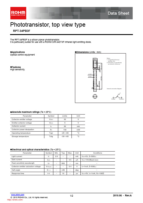
RPT-34PB3F;中文规格书,Datasheet资料
10
4
1
20 10 −25 0 25 50 75 100
2
0.1 −25 0 25 50 75 100
0
250
500
750
1000
1250
AMBIENT TEMPERATURE : Ta (°C)
AMBIENT TEMPERATURE : Ta (°C)
ILLUMINANCE : E (Lx)
Fig.1 Dark current vs. ambient temperature
60° 70° 80° 90°
50° 60
10
40
RL=100Ω 1 0.1
20
1
10
0 10° 20° 30° 40° 50° 60° 70° 80° 90° RELATIVE LUMINOUS INTENSITY : (%) ANGULAR DISPLACEMENT : θ (deg)
COLLECTOR CURRENT : IC (mA)
RELATIVE LUMINOUS INTENSITY: (%)
Ta=25°C VCE=5V
20°
10°
0°
100
RESPONSE TIME : tr (μs)
Notice
Notes
No copying or reproduction of this document, in part or in whole, is permitted without the consent of ROHM Co.,Ltd. The content specified herein is subject to change for improvement without notice. The content specified herein is for the purpose of introducing ROHM's products (hereinafter "Products"). If you wish to use any such Product, please be sure to refer to the specifications, which can be obtained from ROHM upon request. Examples of application circuits, circuit constants and any other information contained herein illustrate the standard usage and operations of the Products. The peripheral conditions must be taken into account when designing circuits for mass production. Great care was taken in ensuring the accuracy of the information specified in this document. However, should you incur any damage arising from any inaccuracy or misprint of such information, ROHM shall bear no responsibility for such damage. The technical information specified herein is intended only to show the typical functions of and examples of application circuits for the Products. ROHM does not grant you, explicitly or implicitly, any license to use or exercise intellectual property or other rights held by ROHM and other parties. ROHM shall bear no responsibility whatsoever for any dispute arising from the use of such technical information. The Products specified in this document are intended to be used with general-use electronic equipment or devices (such as audio visual equipment, office-automation equipment, communication devices, electronic appliances and amusement devices). The Products specified in this document are not designed to be radiation tolerant. While ROHM always makes efforts to enhance the quality and reliability of its Products, a Product may fail or malfunction for a variety of reasons. Please be sure to implement in your equipment using the Products safety measures to guard against the possibility of physical injury, fire or any other damage caused in the event of the failure of any Product, such as derating, redundancy, fire control and fail-safe designs. ROHM shall bear no responsibility whatsoever for your use of any Product outside of the prescribed scope or not in accordance with the instruction manual. The Products are not designed or manufactured to be used with any equipment, device or system which requires an extremely high level of reliability the failure or malfunction of which may result in a direct threat to human life or create a risk of human injury (such as a medical instrument, transportation equipment, aerospace machinery, nuclear-reactor controller, fuelcontroller or other safety device). ROHM shall bear no responsibility in any way for use of any of the Products for the above special purposes. If a Product is intended to be used for any such special purpose, please contact a ROHM sales representative before purchasing. If you intend to export or ship overseas any Product or technology specified herein that may be controlled under the Foreign Exchange and the Foreign Trade Law, you will be required to obtain a license or permit under the Law.
SSL34F规格书SMAF封装YFW二极管

Maximum DC Blocking VoltageParameterMaximum Repetitive Peak Reverse VoltageMaximum RMS voltageMaximum Average Forward Rectified Current 1)Typical Junction Capacitance 40V 28V V 3.0-55 ~ +125AAVm ApF °C UnitsSurface Mount Schottky Barrier Rectifier Reverse Voltage - 40V Forward Current - 3.0AFEATURES• Metal silicon junction, majority carrier conduction• For surface mounted applications • Low power loss, high efficiency• High forward surge current capability• For use in low voltage, high frequency inverters, free wheeling, and polarity protection applicationsAbsolute Maximum Ratings and Electrical characteristicsRatings at ambient temperature unless otherwise specified.Single phase, half wave, 60Hz resistive or inductive load, for capacitive load, derate by 20 %25 °C 40Peak Forward Surge Current,8.3ms Single Half Sine-wave Superimposed on Rated Load (JEDEC method)Max Instantaneous Forward Voltage at 3 AMaximum DC Reverse Current at Rated DC Reverse VoltageOperating Junction Temperature RangeSSL34FT = 25°C a T =100°Ca V RRM V RMS V DC I F(AV)I FSM V F I R C jT j SymbolsT stgStorage Temperature Range0.45-55 ~ +150°C0.354502)50Typical Thermal ResistanceR θJA °C/W 1) Measured at 1MHz and applied reverse voltage of 4 V D.C.2) P.C.B. mounted with 0.5 X 0.5" (12.7 X 12.7 mm) copper pad areas.80MECHANICAL DATA pprox. Weight:• Case: SMAF• Terminals: Solderable per MIL-STD-750, Method 2026• A 27mg / 0.00095ozPINNING PIN 12DESCRIPTION Cathode AnodeTop ViewMarking Code: SSL34Simplified outline SMAF and symbol12Fig.1 Forward Current Derating Curve0.51.01.52.02.53.00.0255075100125150A v e r a g e F o r w a r d C u r r e n t (A )Single phase half-wave 60 Hz resistive or inductive load3.5Fig.4 Typical Junction CapacitanceJ u n c t i o n C a p a c i t a n c e ( p F )Reverse Voltage (V)Fig.3 Typical Forward CharacteristicI n s t a n e o u s F o r w a r d C u r r e n t (A )Instaneous Forward Voltage (V)0.01100110100Fig.6- Typical Transient Thermal ImpedanceT r a n s i e n t T h e r m a l I m p e d a n c e (/W )°C t, Pulse Duration (sec )0.11100.10.51101.01.52.020100.1101005002010011000T =25J °CSSL34F10100Fig.5 Maximum Non-Repetitive Peak Forward Surage CurrentP e a k A )F o r w a r d S u r a g e C u r r e n t (Number of Cycles at 60Hz 8.3 ms Single Half Sine Wave (JEDEC Method)12040600080100SSL34FSingle phase half wave resistive or inductive P.C.B mounted on 0.5×0.5"(12.7)×12.7mm pad areas Fig.2 Typical Reverse CharacteristicsI n s t a n e o u s C u r r e n t ( μA )R e v e r s e 20406080T =25J °CT =100J °CPercent of Rated Peak Reverse Voltage (%)100100101102103104T =75J °CSSL34FLead Temperature (°C)MarkingType numberMarking codeSS 34FL SS 34L PACKAGE OUTLINEPlastic surface mounted package; 2 leadsSMAFAC∠ALL ROUND V AM eUNIT mm1.10.20 3.72.7 4.90.90.123.3 2.44.47°max min milmax min43357.94.714613010694193173A C D E H E∠1.61.36351e Bottom ViewH Eg Top View1.20.84731g g∠ALL ROUNDED AEp a dp a dThe recommended mounting pad size2.2(86)1.6(63)1.8(71)1.6(63)Unit :mm(mil)。
AO3400 SOT-23-3L NMOS Vds30V 规格书AO推荐

ID(A)
15
VDS=5V 12
9
6
125°C 3
25°C
0
0
0.5
1
1.5
2
2.5
3
VGS(Volts) Figure 2: Transfer Characteristics (Note E)
Normalized On-Resistance
RDS(ON) (mΩ)
30
25 VGS=4.5V
20
15
Symbol
Parameter
Conditions
Min Typ Max Units
STATIC PARAMETERS
BVDSS Drain-Source Breakdown Voltage
ID=250µA, VGS=0V
30
V
IDSS
Zero Gate Voltage Drain Current
VDS=30V, VGS=0V
Parameter
Symbol
Drain-Source Voltage
VDS
Gate-Source Voltage
VGS
Continuous Drain Current
TA=25°C TA=70°C
ID
Pulsed Drain Current C
IDM
TA=25°C Power Dissipation B TA=70°C
(Note E)
IS (A)
1.0E+01
1.0E+00
40
1.0E-01
1.0E-02
1.0E-03
125°C
25°C
1.0E-04
1.0E-05
国巨电阻规格书
2005eo.comGenerated: Thu Jan 06 14:30:05 CET 2005; Source: Generated: Thu Jan 06 14:29:15 CET 2005; Source: 1Generated: Thu Jan 06 14:29:18 CET 2005; Source: Note: Value in "Resistance" means the minimum one.Note: Resistance E192; special value on requestNote: TCR=±10ppm/°C; ±15ppm/°C on RequestNote: Tolerance=±0.01%; ±0.05% on RequestNote: Power mode RT0603 on requestGenerated: Thu Jan 06 14:29:34 CET 2005; Source: 3Generated: Thu Jan 06 14:29:41 CET 2005; Source: Note: Value in "Resistance" means the minimum one.Note: TCR=±10ppm/°C; ±15ppm/°C on RequestNote: Tolerance=±0.01%; ±0.05% on RequestGenerated: Thu Jan 06 14:29:49 CET 2005; Source: 5General purpose thin film, 0201-2512Note: Value in "Resistance" means the minimum one.Note: Resistance E192; special value on requestGenerated: Thu Jan 06 14:29:52 CET 2005; Source: Generated: Thu Jan 06 14:29:53 CET 2005; Source: 7Generated: Thu Jan 06 14:29:53 CET 2005; Source: Trimmable, 0805Note: Value in "Resistance" means the minimum one.Arrays, convex and concaveNote: Zero Ohm Jumper<0.05 OhmNote: Value in "Resistance" means the minimum one. Note: 4*0603 (Concave) 1% is on requestNote: 4*1206 (Convex) 1% is on requestNetworkNote: Zero Ohm Jumper<0.05 OhmNote: Value in "Resistance" means the minimum one.Current sensors - Low TCROrdering Information - Single resistor:060307Ordering Information - Array, Network YC164J R0710R L__PaperEmbossedPaperEmbossed02018 mm 10 000---50 000---04028 mm 10 000---50 000---06038 mm 5 000---20 000---08058 mm 5 000---20 000---12068 mm 5 000---20 000---12108 mm 5 000---20 000---121812 mm --- 4 000------201012 mm --- 4 000------251212 mm --- 4 000------YC122 (2x0402)8 mm 10 000---50 000---YC124 (4x0402)8 mm 10 000---40 000---YC/TC16 (4x0603)8 mm 5 000---20 000---YC15 (0616)8 mm 5 000---20 000---YC24 (1220)12 mm 5 000---------YC32/35 (1220/1225)12 mm--- 4 000------Packing QuantitiesSize Code Tape Width 180 mm / 7"330 mm / 13"AsiaYageo Taiwan Tel. +886 (0)2 2917 7555 Fax. +886 (0)2 2917 4286Yageo China, DongguanTel. +86 769 772 0275Fax. +86 769 791 0053Yageo China, SuzhouTel. +86 512 825 5568Fax. +86 512 825 5386Yageo China, BeijingTel. +86 10 851 20810Fax. +86 10 851 20200Yageo Hong Kong Tel. +852 2342 6833Fax. +852 2342 6588Yageo JapanTel. +81 3 5833 3331Fax. +81 3 5833 3116Yageo KoreaTel. +82 31 712 4797Fax. + 82 31 712 5866Yageo Malaysia, PenangTel. +60 4 397 3317Fax. +60 4 397 3272Yageo Malaysia, Kuala LumpurTel. +60 3 5882 2854Fax. +60 3 5882 8700Yageo Singapore Tel. +65-6244 7800Fax. +65-6244 4943EuropeYageo Benelux Tel. +31 475 385 357 Fax. +31 475 385 589Yageo FinlandTel. +358 (0)9 2707 5851Fax. +358 (0)9 2707 5852Yageo FranceTel. +33 1 55 51 84 00Fax. +33 1 55 51 84 24Yageo Germany / CentralEuropeTel. +49 4121 870-0Fax. +49 4121 870-271Yageo Italy / South Europe Tel. +39 02 2411 301Fax. +39 02 2411 3051Yageo UKTel. +44 1372 364500Fax. +44 1372 364567Yageo IberiaTel. +34 93 238 9172Fax. +34 93 415 9951Yageo HungaryTel. +36-30-3777-441Fax. +36-94-517-701Yageo Russia Tel. +7 501 430 96 27 Fax. +7 095 567 02 66Yageo Sweden / NordicTel. +46 8 514 933 55Fax. +46 8 514 933 51Yageo Czech RepublicTel. +420-5-43 23 92 33Fax. +420-5-43 23 92 33North AmericaYageo USA, Seattle Tel. +1 425 492 2818Fax. +1 425 492 2819Yageo USA, Dallas Tel. +1 972 599 0099Fax. +1 972 599 0099。
dsk34二极管手册
dsk34二极管手册
DSK34是一种二极管型号,通常被用于电子设备中。
二极管是
一种电子元件,具有两个电极,被广泛应用于电路中。
DSK34二极
管通常被用于低压整流和保护电路。
在DSK34的手册中,你可以找
到关于这种二极管的详细规格,包括最大额定电压、最大额定电流、封装类型、引脚排列图等信息。
在DSK34的手册中,你还可以找到关于如何正确使用和安装这
种二极管的指导,包括焊接温度、最大允许的反向电压、最大允许
的正向电流等方面的信息。
此外,手册中可能还包括关于该二极管
的典型应用电路以及温度特性曲线等相关信息。
此外,DSK34的手册可能还包括关于该二极管的质量标准、生
产厂家信息、订购代码以及其他相关的技术资料。
如果你需要在特
定应用中使用DSK34二极管,手册中可能还包括关于如何选择合适
的工作点和工作条件的建议。
总之,DSK34二极管手册是了解这种二极管性能、特性和应用
的重要参考资料,通过仔细阅读手册,你可以更好地理解和应用
DSK34二极管。
希望这些信息能够帮助到你。
NTC热敏电阻参数及其对照表
NTC热敏电阻参数及其对照表10K NTC热敏电阻参数及其对照表常温下R25℃ = 10K B(25-85)=343510K NTC热敏电阻负温度系数(NTC电阻随着温度的升高而降低)温度传感器探头是基于一个10K的±1% @ 25ºC传感器-即电阻值在25ºC是10K,一般用途的温度测量,NTC温度传感器可以在很宽的温度范围内工作(-40 + 125°C)他们是稳定的,年/阻值漂移小于1PPM。
10K NTC热敏电阻产品尺寸图:10K 3435NTC热敏电阻特点:1:MF52系列产品为径向绝缘引线,使用时无需引脚绝缘处理2:产品稳定性好,可靠性高,年漂移率小于1PPM3:热敏电阻阻值范围宽:1KΩ~1000KΩ4:阻值及B值精度高,一致性好6:体积小热感应时间快灵敏度高,便于自动化安装7:使用温度范围-40℃~+125℃R25=10K B=3435NTC热敏电阻应用范围:•充电器、温湿度计、美容仪器、电源、电子玩具•气体分析计手机电池、NB电池、电动车电池、医疗仪器•太阳能热水器、冷藏库、汽车、複印机、传真机•电子体温计、电子炉台、电子锅、电热水瓶•即热式热水器、瓦斯热水器、电毯、空调•3C家电产品、石油暖炉、打印机103F3435NTC热敏电阻机械性能标准:MF52产品型号说明MF 52 103 F 3435①MF ——负温度系数(NTC)热敏电阻编号。
②52——树脂封装小黑头热敏电阻(包括漆包线、小皮线)③103 ——热敏电阻的标称阻值(10K欧),表示该电阻标称阻值为:10×103(Ω)。
④F——电阻值的误差(精度)为:S=±0.5% F=±1%,G=±2%,H=±3%,J=±5%⑤3435——电阻的热敏指数(材料系数)B值为:343×10(K)R25=10K B=3435NTC热敏电阻阻温特性R/T表:。
DSK34 SOD-123FL系列规格书推荐
RATINGS AND CHARACTERISTIC CURVES DSK32 THRU DSK310
AVERAGE FORWARD RECTIFIED CURRENT, AMPERES
PEAK FORWARD SURGE CURRENT, AMPERES
FIG. 1- FORWARD CURRENT DERATING CURVE
50 35 50
60 42 60 3.0 80.0
70 49 70
80 56 80
90 63 90
100 70 100
0.52
0.55 20.085 10.0 -50 to +150
Volts mA C C
-50 to +150
1 of 2
深圳理悠科技有限公司
2.8±0.1 1.3± 0.15 0.10-0.30 0.6±0.25
1.0±0.2
1.8± 0.1
MECHANICAL DATA
Case: JEDEC SOD-123FL molded plastic body Terminals: Plated axial leads, solderable per MIL-STD-750, Method 2026 Polarity: Color band denotes cathode end Mounting Position: Any Weight:0.0007 ounce, 0.02 grams
1 TJ=75 C
0.1
DSK32-DSK34 DSK35-DSK36 DSK37-DSK310
0.2 0.4 0.6 0.8 1.0 1.1
0.1
0.01
0.01
TJ=25 C