ANSYS在压力容器设计中的应用
基于ANSYS对压力容器的应力分析与结构优化
1 压力容器 的应 力分布
压力容器设计时 , 一般首先按 照“ 等安全裕度”类 ,然后按照各种应力 的作用及性质判断 其危险『而给予不同的控制值 。 生
侧 过渡 圆弧 半径 R。 1m = 0 m,内侧 应 力释 放槽 圆弧 半径 R =
1mm, 0 容器最高工作压力 P 2 a = MP ( 设计压力 21 P )容器材料 .M a,
6 R, = x 0 MP , 泊 z ., = . / k 压力容器中 ,由内压产生 的薄膜应力为一次总体薄膜应力 1Mn 弹性 模 量 E 2 l5 a 松 比 / 03 材料 密度 78 g m, 2 0 a P 由满足结构 连续 所需要 的 自平衡应力 威二 次应力 Q, 发 m 许 用 应 力= 5 MP 。 m; 其
基 于 A YS对压 力容 器的应 力分析 与结构优化 NS
董 龙梅 杨 涛 孙 显 ( 内蒙古 工业大 学 机械 学 院 , 和浩 特 0 0 5 ) 呼 10 1
St s n lssa ds r c u eo t z t no r s u ev s e nANSYS r sa ay i n tu t r p i a i f e s r e s l e mi o p o
中图分类 号 :H1 3T 4 2 文献标 识码 : T 2 ,B 7 A
随着 核容器和大型化高参数化 工容器 的广泛使用 ,以往所 部 薄 膜 应 力 。 采用的基于弹性失效准则的按“ 规则设计” 法已不能完全适应 方
根据应力分类 , 平板封头压力容器 中, 基本壁厚部分总应力
工 程设 计 的要 求 ,基 于 塑性 失 效 准 则 的分 析 设 计 越 来 越 多 的应 为 P Q F 由于释放槽 圆弧 ( m+ + ; 如图 1 所示 , 半径为 R1 0的半 圆) 用到现代容器 的设计 中。分析设计 的基础首先是对容器关键部 处 为几何不 连续区 ,故此处 由内压产生 了一 次局部薄 膜应力
利用ANSYS软件对压力容器进行应力分析

利用ANSY S软件对压力容器进行应力分析韩 敏(西安科技大学,西安710054)摘要:利用ANSY S有限元软件对压力容器进行应力分析,获得了压力容器的应力分布图。
经分析发现,ANSY S软件分析的结果与真实情况基本一致。
整个建模、分析过程充分说明ANSY S 软件为压力容器的结构设计提供了可靠、高效的理论依据。
关键词:压力容器;ANSY S;有限元;应力分析中图分类号:TH49 文献标志码:A 文章编号:100320794(2008)0120073202Stress Analysis of Pressure Contain with ANSY S Softw areH AN Min(X i’an University of Science and T echnology,X i’an710054,China)Abstract:The static force im paction of a pressure contain with ANSY S s oftware was analysed and the stress distribution drafts of them were g otten.Through theories analysis,the result of finite-element analysis is proved to be acceptable,and it provides the theories support to today’s machine optimize design.K ey w ords:pressure contain;ANSY S;finite-element;stress analysis计方法,得出的结构强度结果比较保守,这就限制了容器整体性能的提高和材料的有效利用。
分析设计依据标准JB4732《钢制压力容器—分析设计标准》,它是基于“塑性失效”与“弹塑性失效”准则,其理论基础是板壳力学、弹性与塑性理论及有限元法,是根据具体工况,对容器各部位进行详细地应力计算与分析,在不降低设备安全性的前提下选取相对较低的安全系数,从而降低了结构的厚度,使材料得到了有效的利用。
基于ANSYS Workbench的压力容器封头设计

基于ANSYS Workbench的压力容器封头设计
计雪洁;张陈
【期刊名称】《现代制造技术与装备》
【年(卷),期】2018(0)11
【摘要】针对压力容器平板封头和椭圆形封头,先利用公式进行推导得出二者理论应力值,然后利用ANSYS Workbench软件对压力容器的平板封头和椭圆形封头进行应力模拟分析,并与理论值进行比较.二者数值相互验证之后,指出在设计压力容器封头时,两种封头在工程应用中的优缺点,为压力容器封头设计提供有效的理论依据.【总页数】3页(P44-45,47)
【作者】计雪洁;张陈
【作者单位】沈阳工程学院研究生部沈阳 110136;沈阳工程学院机械学院沈阳110136
【正文语种】中文
【相关文献】
1.基于ANSYS Workbench封头应力分析 [J], 季雪平;吕浩强;季雪娟
2.基于ANSYS Workbench的球冠形封头与筒体连接处的应力分析 [J], 李晓红;李卫红;王思莹
3.基于ANSYS Workbench的压力容器筒体与封头连接区的应力分析 [J], 程魁;高勇;王勇
4.基于ANSYS Workbench的封头切向接管有限元应力分析 [J], 孙志刚;王波;褚建伟;田野;吕海玲;李娜
5.基于ANSYS Workbench的不同形式压力容器封头的应力分析 [J], 邵海磊; 郭海伟
因版权原因,仅展示原文概要,查看原文内容请购买。
实例分析—运用有限元分析软件ANSYS对轴对称压力容器
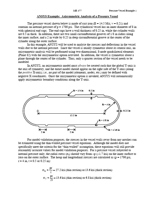
ANSYS Example: Axisymmetric Analysis of a Pressure VesselThe pressure vessel shown below is made of cast iron (E = 14.5 Msi, ν = 0.21) andcontains an internal pressure of p = 1700 psi. The cylindrical vessel has an inner diameter of 8 in with spherical end caps. The end caps have a wall thickness of 0.25 in, while the cylinder walls are 0.5 in thick. In addition, there are two small circumferential grooves of 1/8 in radius along the inner surface, and a 2 in wide by 0.25 in deep circumferential groove at the center of the cylinder along the outer surface.In this example, ANSYS will be used to analyze the stresses and deflections in the vessel walls due to the internal pressure. Since the vessel is axially symmetric about its central axis, an axisymmetric analysis will be performed using two-dimensional, 8-node quadrilateral elements (Plane 82) with the axisymmetric option activated. In addition, the vessel is symmetric about a plane through the center of the cylinder. Thus, only a quarter section of the vessel needs to be modeled.In ANSYS, an axisymmetric model must always be created such that the global Y-axis is the axis of symmetry, and the entire model should appear on the right side of the Y-axis (along the positive X-axis); i.e., no part of the model (elements, nodes, etc.) may be defined withnegative X coordinates. Once the axisymmetric option is invoked, ANSYS will automatically apply axisymmetric boundary conditions along the Y-axis.R = 1/16 inR = 1/8 inR = 1/4 in 0.5 in0.25 inR = 4 in2 in 2 in 15.5 inFor model validation purposes, the stresses in the vessel walls away from any notches can be estimated using the thin-walled pressure vessel equations. Although the model does notspecifically meet the criteria for the “thin-walled” assumption, these equations will still provide reasonably accurate values for model validation purposes. For a pressure vessel subjected to internal pressure only, the radial stress (σr ) should vary from –p (−1.7 ksi) on the inner surface to zero on the outer surface. The hoop and longitudinal stresses are calculated as (p = 1700 psi, r = 4 in, t = 0.5 or 0.25 in):section)(thick ksi 13.6or section)(thin ksi 27.2tpr h =≈σ section)(thick ksi 6.8or section)(thin ksi 6.31t2pr =≈σlANSYS Analysis:Start ANSYS Product Launcher, set the Working Directory to C:\temp, define Job Name as‘Pressure Vessel’, and click Run. Then define Title and Preferences.Utility MenuÆFileÆChange Jobname…Æ Enter ‘Pressure_Vessel’ Æ OKUtility MenuÆFileÆChange Title…Æ Enter ‘Stress Analysis of an Axisymmetric Pressure Vessel’ Æ OKANSYS Main MenuÆPreferencesÆ Preferences for GUI Filtering Æ Select ‘Structural’ and ‘h-method’ Æ OKEnter the Preprocessor to define the model geometry:Define Element Type (Axisymmetric Option) and Material Properties.ANSYS Main MenuÆPreprocessor ÆElement Type Æ Add/Edit/Delete Æ Add… ÆStructural Solid Quad 8 node 82 (PLANE82) (define ‘Element type reference number’ as 1) ÆOK Æ Click Options… Æ Select ‘Axisymmetric’ for K3 (Element behavior) Æ OK Æ Close ANSYS Main MenuÆPreprocessorÆMaterial PropsÆ Material Models Æ Double Click Structural Æ Linear Æ Elastic Æ Isotropic Æ Enter 14.5e6 for EX and 0.21 for PRXY Æ Click OK Æ Click Exit (under ‘Material’)Begin creating the geometry by defining two Circles for the spherical endcap, and Subtract Areas to create the vessel wall.ANSYS Main MenuÆPreprocessorÆModelingÆCreateÆAreasÆCircleÆ Solid Circle Æ Enter 0 for WP X, 0 for WP Y, and 4 for Radius Æ Apply Æ Enter 0 for WP X, 0 for WP Y, and 4.25 for Radius Æ OKANSYS Main MenuÆPreprocessorÆModelingÆOperateÆBooleansÆSubtractÆAreas Æ Select (with the mouse) Area 2 (bigger circle) Æ OK Æ Select Area 1 (smaller circle) Æ OKCreate Lines through the center of the Circles and Divide the Areas along these Lines.ANSYS Main MenuÆPreprocessorÆModelingÆCreateÆLinesÆLinesÆ Straight line Æ Click on the Keypoints on the outer circle which are on the X-axis to create a Line parallel to the X-axis (Circles are divided into four arcs by Ansys, with a Keypoint placed at the end of each arc). Similarly, click on the Keypoints on the outer circle which are on the Y-axis to create a Line parallel to the Y-axis Æ OKANSYS Main MenuÆPreprocessorÆModelingÆOperateÆBooleansÆDivideÆArea by Line Æ Select (with the mouse) the remaining Area (annulus)Æ OK Æ Select the two Lines that we have created Æ OKANSYS Main MenuÆPreprocessorÆModelingÆDeleteÆ Area and Below Æ Select the three Areas in the first, second, and third quadrants Æ OKDefine two Rectangles to create the walls of the cylindrical portion of the vessel (thick and thin sections). Define a Circle to create the circumferential groove on the inside of the vessel. ANSYS Main MenuÆPreprocessorÆModelingÆCreateÆAreasÆRectangleÆ By Dimensions Æ Enter 4 and 4.5 for X-coordinates and 0 and 7.75 for Y-coordinates Æ Click Apply Æ Enter 4.25 and 4.5 for X-coordinates and 6.75 and 7.75 for Y-coordinates Æ OK ANSYS Main MenuÆPreprocessorÆModeling ÆCreateÆAreasÆCircleÆ Solid Circle Æ Enter 4 for WP X, 2 for WP Y, and 1/8 for Radius Æ OKSubtract Areas to eliminate unused segments, and then Add all Areas to create a single Area for meshing.ANSYS Main MenuÆPreprocessorÆModelingÆOperateÆBooleansÆSubtractÆAreas Æ Select (with the mouse) the bigger rectangle Æ OK Æ Select the small rectangle and circle Æ OKANSYS Main MenuÆPreprocessorÆModelingÆOperateÆBooleansÆAddÆ Areas Æ Select ‘Pick All’ Æ OKCreate Line Fillets at the two transitions between the thick and thin sections.Utility Menu Æ Plot ÆLinesUtility Menu Æ Plot CtrlsÆNumbering…Æ Click ‘Line numbers’ On Æ OKANSYS Main MenuÆPreprocessorÆModelingÆCreateÆLinesÆ Line Fillet Æ Select (with the mouse) the two Lines near the lower Fillet Æ OK Æ Enter 1/16 for Fillet radius ÆApply Æ Select the two Lines near the upper Fillet Æ OK Æ Enter 1/4 for Fillet radius Æ OK Create Areas within the two Fillets and add these Areas to the main Area. First zoom in on the area of interest using the plot controls.ANSYS Main MenuÆPreprocessorÆModelingÆCreateÆAreasÆArbitraryÆ By Lines Æ Select (with the mouse) the Fillet and adjacent two Lines Æ OKRepeat for the other Fillet.ANSYS Main MenuÆPreprocessorÆModelingÆOperateÆBooleansÆAddÆ Areas Æ Select ‘Pick All’ Æ OKUtility Menu Æ Plot ÆLinesThe geometry should appear as shown below in the figure on the left.In this example, the irregular geometry will be Free Meshed with Quad Elements. Better control of Element sizing and distribution can be obtained with Mapped Meshing, but this would require that additional sub-Areas be defined within the main Area that have a regular (four-sided) geometry. Using Free Meshing, all Elements in the model will be approximately the same size. In the first run, we will choose a Global Size (approximate Element edge length) of 0.1 in. ANSYS Main MenuÆPreprocessorÆMeshingÆ MeshTool Æ Under ‘Size Controls: Global’ click Set Æ Enter 0.1 for ‘Element edge length’ ÆOK Æ Under ‘Mesh:’ select Areas, Quad and Free Æ Click Mesh Æ Select (with the mouse) the Area Æ OKEnter the Solution Menu to define boundary conditions and loads and run the analysis: ANSYS Main MenuÆSolutionÆAnalysis TypeÆ New Analysis Æ Select Static Æ OK The Boundary Conditions and Loads can now be applied. ANSYS will automatically apply the Axisymmetric Boundary Conditions along the Y-axis. However, we must apply the Symmetry Boundary Conditions along the upper edge of the model. Finally, the Pressure can be applied on all lines that make up the inner surface of the vessel. The magnitude should be input as the actual value – no reduction is needed to account for axisymmetry (ANSYS automatically makes the necessary adjustment of Loads in an Axisymmetric model).ANSYS Main MenuÆSolutionÆDefine LoadsÆApplyÆStructuralÆDisplacement ÆSymmetry B.C.Æ On Lines Æ Select the Line on top of the model (19) Æ OKANSYS Main MenuÆSolutionÆDefine LoadsÆApplyÆStructuralÆPressureÆ On Lines Æ Select (with the mouse) all the Lines on the inside of the vessel (20,12,16,17 and 2) ÆOK Æ Enter 1700 for ‘Load PRES value’ Æ OKThe pressure will be indicated by arrows, as shown above in the figure on the right.Save the Database and initiate the Solution using the current Load Step (LS).ANSYS Toolbar Æ SAVE_DBANSYS Main MenuÆSolutionÆSolveÆ Current LS Æ OK Æ Close the information window when solution is done Æ Close the /STATUS Command windowEnter the General Postprocessor to examine the results:First, plot the Deformed Shape.ANSYS Main MenuÆGeneral PostprocÆPlot ResultsÆ Deformed Shape Æ Select Def + undeformed Æ OKA Contour Plot of any stress component can be created. The radial, hoop (tangential), and longitudinal stresses should be checked to verify the model. Also, stress values at any particular node can be checked by using the “Query Results” command, selecting the desired component, and then picking the appropriate node. For this model, along the cylindrical portion of the vessel, x represents the radial direction, y represents the longitudinal direction, and z represents the hoop (tangential) direction. Powergraphics must be disabled to query results at nodes. ANSYS Toolbar Æ POWRGRPH Æ Select OFF Æ OKANSYS Main MenuÆGeneral PostprocÆPlot ResultsÆContour PlotÆ Nodal Solu ÆSelect ‘Stress’ and ‘X-Component of stress’ (or Y or Z) Æ OKANSYS Main MenuÆGeneral PostprocÆQuery ResultsÆ Nodal Solution Æ Select‘Stress’ and ‘X-direction SX’ (or SY or SZ) Æ OK Æ Select Nodes in the region of interest (may be helpful to zoom in on region)Compare the finite element stresses to the values calculated using the thin-wall equations. If the values are within reason (away from notches, etc.), proceed. For the purposes of failure analysis, we must select an appropriate failure theory. A plot of the von Mises stress is useful for identifying critical locations in the vessel. However, since the vessel is made of cast iron (brittle material), the “Maximum-Normal-Stress” failure criterion may be more appropriate (or Coulomb-Mohr or other similar failure theories). Create Contour Plots of the von Mises and 1st Principal stresses.ANSYS Main MenuÆGeneral PostprocÆPlot ResultsÆContour PlotÆ Nodal Solu ÆSelect ‘Stress’ and ‘von Mises stress’ Æ OKANSYS Main MenuÆGeneral PostprocÆPlot ResultsÆContour PlotÆ Nodal Solu ÆSelect ‘Stress’ and ‘1st Principal stress’ Æ OKThe plot of the model can be expanded around the axisymmetric axis to get a better view of the full model. For this plot, Powergraphics must be enabled.ANSYS Toolbar Æ POWRGRPH Æ Select ON Æ OKUtility Menu Æ PlotCtrlsÆStyleÆ Symmetry Expansion Æ 2-D Axi-Symmetric… Æ Select ‘Full expansion’ Æ OKNote the locations of the maximum stresses in the vessel. Are the critical locations where you would expect them to be? If not, why? Do you think the current model is accurate, or might there be some discretization error? Record the magnitudes and locations of the maximum stresses, and then refine the mesh and re-run the analysis to check for possible discretization error.。
基于ANSYS的压力容器螺栓连接有限元分析
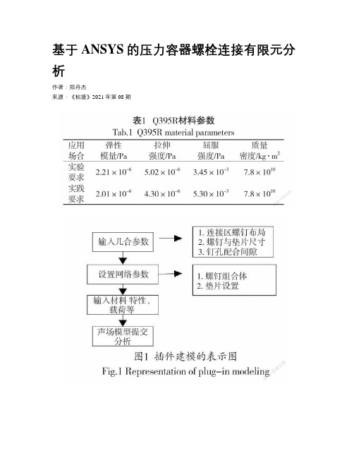
基于ANSYS的压力容器螺栓连接有限元分析作者:***来源:《粘接》2021年第08期摘要:根据GB 150.1—150.4-2011《压力容器》以及有关设计实践,可知压力容器螺栓的常规设计方法偏向于稳定性,因此造成其各部位所受拉力较高,材料损耗严重。
基于此,提出基于ANSYS的压力容器螺栓连接有限元分析。
以有限元分析为基础,输入材料参数,对连接结构进行参数化建模,选择单元格类型及划分网格,规定约束和边界条件,计算螺栓组剪力及工作拉力。
实验得知,本设计方法与传统方法相比,在受力方面较小,即表面处的径向应力约等于内表面上的压力,具有较高实用性。
关键词:压力容器;ANSYS;螺栓连接;有限元中图分类号:TH49 文献标识码:A 文章编号:1001-5922(2021)08-0136-04Finite Element Analysis of Bolt Connection ofPressure Vessel Based on ANSYSZheng Zhoujie(Zhuhai Technician College, Zhuhai 519000, China)Abstract:According to GB 150.1—150.4—2011 “Pressure Vessel” and related design practice, it can be seen that the conventional design method of pressure vessel bolts is inclined to stability, which results in high tension and serious material loss in each part. Based on this, the finite element analysis of bolt connection of pressure vessel based on ANSYS is proposed. Based on finite element analysis, input material parameters, carry out parametric modeling of the connection structure, select cell types and divide grids, specify constraints and boundary conditions, andcalculate bolt group shear force and working tension. Experimental show that compared with traditional methods, the design method in this paper has less stress, that is, the radial stress on the surface is approximately equal to the pressure on the inner surface, which has high practicability.Key words:pressure vessel; ANSYS; bolted connection; finite element0 引言压力容器作为重要的存储设备,被广泛应用在化工、能源、冶金以及石油等诸多领域内。
基于ANSYS的压力容器有限元分析及优化设计

基于ANSYS的压力容器有限元分析及优化设计
续俊
【期刊名称】《石化技术》
【年(卷),期】2024(31)4
【摘要】由于压力容器常规的设计方法偏向安全性,在用材上留有富余,导致产品的经济性较差。
为此本文采用ANSYS对压力容器进行仿真分析,对压力容器结构强度、密封性能展开研究,得到压力容器处于工作状态时的应力及变形分布情况。
对压力容器的传统设计方案的优化设计提供了参考。
【总页数】2页(P317-318)
【作者】续俊
【作者单位】山西阳煤化工机械(集团)有限公司
【正文语种】中文
【中图分类】TH4
【相关文献】
1.基于ANSYS Workbench的压力容器有限元分析及优化设计
2.基于ANSYS的压力容器壁厚优化设计
3.基于ANSYS的压力容器壁厚优化设计
4.基于有限元分析法的复合材料球头销成型过程仿真优化——评《压力容器全模型ANSYS分析与强度计算新规范》
5.基于ANSYS Workbench的压力容器结构尺寸优化设计
因版权原因,仅展示原文概要,查看原文内容请购买。
基于ANSYS的压力容器的应力分析与结构优化

基于ANSYS的压力容器的应力分析与结构优化作者:成鹏涛来源:《中国化工贸易·下旬刊》2018年第08期摘要:本文利用ANSYS有限元分析软件对缓冲压力容器进行了应力分析和壁厚优化。
在满足应力强度的条件下,得到了合理的方案。
容器质量降低17.5%,球形封头壁厚降低16.7%,由此可见优化效果明显。
关键词:压力容器;应力分析;优化设计;壁厚;ANSYS;缓冲器压力容器是一种广泛应用于石油化工、机械、轻工、食品等行业的压力容器设备。
传统的压力容器设计采用规则设计,即按照标准GB150《钢制压力容器》。
为了确保安全的容器,设计师总是试图增加壁厚提高压力容器的承载能力,结构强度的结果是相对保守的,这限制了容器的整體性能的提高和材料的有效使用。
随着分析设计理念的发展,越来越多的设计人员优化了压力容器的结构。
本文利用ANSYS有限元分析软件对容器各部分进行了详细的应力计算和分析,以容器的最小质量为目标,不降低设备的安全性。
通过优化设计方法,给出了压力容器参数的最优组合,以减小结构的厚度,有效地提高材料使用效率。
1 压力容器参数及应力云图1.1 工作条件和结构参数有一缓冲器,整个缓冲器封头材料为16MnR,接管材料为16Mn,其参数见表1。
设计压力p=32MPa,弹性模量E=206GPa,泊松比μ=0.3。
壁厚参考范围t1=30~39mm,t2=15~24mm,许用应力[σ]=250MPa。
1.2 参数化建模根据结构特点和荷载特性,采用轴对称力学模型进行分析,从关键点生成曲面,建立二维模型。
该结构采用PLANE82进行网格划分,这是ANSYS软件提供的8个节点的轴对称单元。
1.3 施加载荷及应力分布有限元分析的目的是了解模型对外界荷载的响应。
使用有限元分析工具的关键步骤是正确识别和定义负载,有效地实现仿真负荷。
在这种情况下,压力容器内表面的压力为32MPa,对球形头末端的对称面施加对称约束。
管道末端的轴向拉伸应力为:得到了应力结果。
基于ANSYS的压力容器应力分析

沿压力容器内壁施加压力P(P=12.0Mpa), 在压力容器的封头处,法兰对压力容器的作用力 可以当做一个集中力F处理,(其中F=-81000 N 方 向向下)。施加载荷后的压力容器有限元模型如 图4所示。
图4 施加载荷
4 查看分析结果
压力容器受内部压力与外部机械载荷的综合 作用,这两类载荷在较长时间段内可以是固定不 变化的或者变化很小的,所以仅需要对压力容
5 沿内外壁的应力分布
在压力容器的应力分析中,通常所关心的是应 力沿壁厚的分布规律以及大小。从应力云图不能详 细的获得沿压力容器壁厚各个关键点的具体应力 值,也不容易直观的获得沿压力容器壁厚的各个关 键点的应力变化情况。所以需要沿压力容器壁定义 相应路径。为了具体比较和分析沿压力容器内壁和 外壁的应力分布情况,本文中分别沿压力容器内壁 创建路径Path-1,沿压力容器外壁创建路径Path-2。 应力沿压力容器壁厚分布如图7和图8所示。
从沿压力容器内壁(Path-1)应力分布图可以
【下转第5页】
图9 模具三维虚拟拆装单机版执行情况
3 结论
基于Solidworks软件进行了模具的三维建模,
利用Eon Studio软件实现了模具的虚拟拆装,并 通过Visual Basic6.0软件进行开发,实现了模块集 成,建立了模具虚拟拆装系统。该系统的实现为 设计的更改和优化提供了制造依据,也为实验教 学提供了分析工具和辅助手段。在一定程度上实 现了模具立体化教学,为学生自主学习能力的开 发提供了理论平台。
参考文献:
[1] 王岚.虚拟现实EONStudio应用教程[M].天津:南开大学 出版社,2007.
[2] 罗陆峰,文领,徐超辉.基于Eon Studio模具虚拟拆装系统 开发[J].煤矿机械,2012,33(6):263-265.
- 1、下载文档前请自行甄别文档内容的完整性,平台不提供额外的编辑、内容补充、找答案等附加服务。
- 2、"仅部分预览"的文档,不可在线预览部分如存在完整性等问题,可反馈申请退款(可完整预览的文档不适用该条件!)。
- 3、如文档侵犯您的权益,请联系客服反馈,我们会尽快为您处理(人工客服工作时间:9:00-18:30)。
压力容器----ANSYS在工业产品设计中的应用(1)
压力容器是石油化工行业的重要设备,对于压力容器的设计至关重要,在设计研发过程中常涉及到强度、稳定性、疲劳寿命等多方面的工程问题。
随着现代CAE仿真技术的日趋成熟,企业完全可以将这种先进的研发手段与试验和经验相结合,形成互补,从而提升研发设计能力,有效指导新产品的研发设计,节省产品开发成本,缩短开发周期,从而大幅度提高企业的市场竞争力。
安世亚太ANSYS仿真工具在1996年通过压力容器标准化委员会认定。
下文是CAE仿真技术在解决压力容器产品研发部分常见工程问题的简要介绍:
一、压力容器的强度问题
✓压力容器整体强度、变形分析
✓封头、开孔及补强零部件校核
✓压力容器热应力分析
✓法兰连接的螺栓强度分析
✓压力容器稳定性分析
压力容器在结构设计中需要考虑不同工作状态下的应力和变形。
ANSYS软件可以帮助解决在不同的工况条件下,结构零部件的强度、刚度及稳定性校核问题。
二、压力容器的动力学问题
1.压力容器的模态分析
✓压力容器的瞬态动力学分析
✓压力容器的随机振动分析
✓压力容器的谱分析
ANSYS软件可以分析压力容器在诸如地震载荷下的瞬态动力学响应分析,通过输出零部件的位移随时间变化的曲线,分析压力容器的最大动应力。
三、压力容器的疲劳问题
✓压力容器焊接接头的疲劳分析
✓热应力的疲劳分析
✓振动疲劳分析
产品的抗疲劳性能和可靠性会直接影响其在市场竞争中的成败。
ANSYS高级疲劳分析和设计软件可以分析压力容器在交变载荷等的疲劳分析。
四、压力容器的优化分析
✓阀门、封头等零部件的优化设计
✓压力容器整体质量优化
对压力容器以及阀门等零部件三维有限元强度分析与结构形状优化设计,以达到重量最轻、或应力最小、或寿命最长、或温度分布最均匀等目标。
五、相关CAE软件模块介绍
✓几何建模:AnsysDesignModeler、Ansys SCDM
✓结构仿真分析:AnsysMechanical
✓疲劳寿命分析:AnsysnCodeDesignlife、Fe-safe、Ansys Fatigue
✓设计优化分析:AnsysDesignXplorer。