Lenses Handbook-Camera Vision
KODAK VISION3 50D 色彩肤色胶片 5203 7203的PDF文件说明书
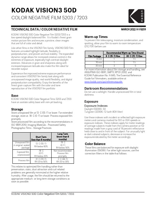
KODAK VISION3 50DCOLOR NEGATIVE FILM 5203 / 7203TECHNICAL DATA / COLOR NEGATIVE FILM MARCH 2022H-1-5203 KODAK VISION3 50D Color Negative Film 5203/7203 is alow-speed daylight-balanced film. It is Kodak’s finest grainmotion picture film and ensures a pristine, clean imagesthat are full of color and detail.Like other films in the VISON3 Film family, VISION3 50D Filmfeatures unrivaled highlight latitude, flexibility inpostproduction, and proven archival stability. The expandeddynamic range allows for increased creative control in theextremes of exposure, especially high contrast daylightexteriors. Advances in grain and sharpness along withincreased exposure latitude also make this film ideal forrecorder output.Experience the improved extreme exposure performanceand consistent VISION3 Film family look along withunsurpassed image quality, real-world flexibility, and digitalpostproduction compatibility. Enjoy the benefits of thefinest grain capture film with the color and tonereproduction of the VISION3 Film portfolioBaseKODAK VISION3 50D Color Negative Films 5203 and 7203have an acetate safety base with rem-jet backing.StorageStore unexposed film at 13 C (55 F) or lower. For extendedstorage, store at -18 C (0 F) or lower. Process exposed filmpromptly.Store processed film according to the recommendations inISO 18911:2010, Imaging Materials - Processed SafetyPhotographic Films - Storage Practices.Short Term (less than 6 months)Long Term (more than 6 months)Unexposed film in original, sealedpackage13 C (55 F)RH below 60%-18 C(0 F)RH below 50%Exposed film, unprocessed-18 C(0 F)RH below 20%Not recommended.Process filmpromptly.Process film21 C (70 F)RH 20 to 50%2 C (36 F)RH 20 to 30%This relates to optimized film handling rather than preservation; static, dust-attraction and curl-related problems are generally minimized at the higher relative humidity. After usage, the film should be returned to the appropriate medium- or long-term storage conditions as soon as possible. Warm-up TimesTo prevent film telescoping, moisture condensation, and spotting, allow your film to warm to room temperature (21C/70F) before use:Film PackageRecommended Warm-up Time (Hours)8 C (15 F) Rise 39 C (70 F) Rise8 mm 1 1 ½16 mm 1 1 ½35 mm 3 5For more information about film storage and handling, see ANSI/PIMA ISO-18911, SMPTE RP131-2002, andKODAK Publication No. H-845, The Essential Reference Guide for Filmmakers, available online at/go/referenceguide.Darkroom RecommendationsDo not use a safelight. Handle unprocessed film in total darkness.ExposureExposure IndexesDaylight (5500K): 50Tungsten (3200K): 12 (with 80A filter)Use these indexes with incident or reflected light exposure meters and cameras marked for ISO or ASA speeds or exposure indexes. These indexes apply for meter readings of average subjects made from the camera position or for readings made from a gray card of 18 percent reflectance held close to and in front of the subject. For unusually light or dark colored subjects, decrease or increase the exposure i ndicated by the meter accordingly.Color BalanceThese films are balanced for exposure with daylight illumination (5500K). For other light sources, use the correction filters in the table that follows.Daylight (5500 K)None50 Metal Halide None50H.M.I.None50 KINO FLO 55None50 Tungsten (3000 K)WRATTEN 2 OpticalFilter / 80A12Tungsten (3200 K)WRATTEN 2 OpticalFilter / 80A 12KINO FLO 29 KINO FLO 32WRATTEN 2 OpticalFilter / 80A12Fluorescent, WarmWhite †Color CompensatingCC20M + CC05R25Fluorescent, CoolWhite †Color CompensatingCC40B20* These are approximate corrections only. Make final corrections during printing.† These are starting-point recommendations for trial exposures. If the kind of lamp is unknown, a KODAK Color Compensating Filter CC20M + CC10B can be used with an exposure index (EI) of 25.Note: Consult the manufacturer of high-intensity ultraviolet lamps for safety information on ultraviolet radiation and ozone generation.Exposure Table-Daylight IlluminationAt 24 frames per second (fps), 180-degree shutter opening, use this table for average subjects that contain a combination of light, medium, and dark colors:Lens Aperture f/1.4f/2f/2.8f/4f/5.6f/8f/11f/16FootcandlesRequired50100 200400800160032006400Reciprocity CharacteristicsYou do not need to make any filter corrections or exposure adjustments for exposure times from 1/1000 of a secondto 1 second.ProcessingProcess in Process ECN-2.Most commercial motion-picture laboratories provide a processing service for these films. See KODAK Publication No. H-24.07, Processing KODAK Color Negative Motion Picture Films, Module 7 available online at/go/h24, for more information on the solution formulas and the procedure for machine processing these films. There are also pre-packaged kits available for preparing the processing solutions. For more information on the KODAK ECN-2 Kit Chemicals, check Using KODAK Kit Chemicals in Motion Picture Film Laboratories KODAK Publication No. H-333, availableonline at /go/h333.IdentificationAfter processing, the product code numbers 5203, or 7203 emulsion, roll, and strip number identification, KEYKODE Numbers, and manufacturer/film identification code (ER) are visible along the length of the film.Post-ProductionScanningThe wider exposure latitude in KODAK VISION3 Films differentiate film capture from the limited dynamic range of digital capture. Digital "dodging and burning," a very powerful tool in the colorists' toolkit, is now even more powerful—up to two stops more image information canbe extracted from scene highlights in VISION3 Films.If traditional 10-bit scanner data encoding schemes are used to digitize films having this extended density range, highlight information captured on these films could be lost. Kodak has recommendations for extracting the full density range stored on highdynamic range films in a technical document titled Scanning Recommendations for Extended Dynamic Range Camera Films, available online at/go/scanning.Laboratory Aim Densities (LAD)To maintain optimum quality and consistency in the final prints, the laboratory must carefully control the color timing, printing, and duplicating procedures. To aid in color t iming and curve placement, negative originals should be t imed relative to Laboratory Aim Density (LAD) Control Film. The LAD Control Film provides both objective sensitometric control a nd subjective verification of the duplicating procedures used by the laboratory.In the LAD Control Method, the electronic color analyzer used for color timing is set-up with the LAD Control Film to produce a gray video display of the LAD patch, corresponding to 1.0 neutral density (gray) on the print. The negative printing original is then scene-to-scene timed. There are specific LAD values for each type of print or duplicating film that the original can be printed on. For print films, the LAD patch is printed to a neutral gray of 1.0 visual density. For duplicating films, the specified aims are at the center of the usable straight-line portion of the sensitometric curve of the film.Due to normal variations in exposure and processing of color negative films, particular scenes may not print exactly at the same printer lights as the LAD Control Film. The LAD Control Film is intended as a set-up tool for electronic color analyzers and printers. It is NOT a reference that every scene must match. Normal film-to-film and scene-to-scene exposure variability is accommodated by the color timing (grading) process, on an electronic color analyzer set up with the LAD Control Film. Normally exposed and processed color negatives will typically print well within the range of an additive printer setup with the LAD Control Film, although SIGNIFICANT or UNEXPECTED departures from this center point balance may indicate an exposure/filtration problem with the cinematography or with the process control. Some specialized films and/or specialized negative processing techniques (push-processing, pull-processing, "skip-bleach" processing, etc.) may require more extreme adjustment from the LAD printing condition to attain desired results.More information is contained in KODAK Publication H-61,Image StructureFor more information on image-structure characteristics, see KODAK Publication No. H-845, The Essential Reference Guide for Filmmakers available online at /go/referenceguide .Modulation Transfer FunctionThe "perceived" sharpness of any film depends on various components of the motion picture production system. The camera and projector lenses and film printers, among other factors, all play a role. But the specific sharpness of a film can be measured and is charted in the Modulation Transfer Function Curve.This graph shows a measure of the visual sharpness of this film. The x-axis, “Spatial Frequency,” refers to the number of sine waves per millimeter that can be resolved. The y-axis, “Response,”corresponds to film sharpness. The longer and flatter the line, the more sine waves per millimeter that can be resolved with a high degree of sharpness — and the sharper the film.rms GranularityThe “perception” of the graininess of any film is highly dependent on scene content, complexity, color, and density. Other factors, such as film age, processing,exposure conditions, and telecine transfer may also have significant effects.Read with a microdensitometer, using a 48-micrometre aperture. To find the rms Granularity value for a given density, find the density on the left vertical scale and follow horizontally to the characteristic curve and then go vertically (up or down) to the granularity curve. At that point, follow horizontally to theGranularity Sigma D scale on the right. Read the number and multiply by 1000 for the rms value.Note: This curve represents granularity based on modified measuringtechniques. Sensitometric and Diffuse RMS Granularity curves are produced on different equipment. A slight variation in curve shape may be noticed.SensitometryThe curves describe this film's response to red, green, and blue light. Sensitometric curves determine the change in density on the film for a given change in log exposure.Spectral SensitivityThese curves depict the sensitivity of this film to the spectrum of light. They are useful for determining,modifying, and optimizing exposure for blue- and green-screen special-effects work.Spectral Dye-Density CurvesThese curves depict the spectral absorption of the dyesformed when the film is processed. They are useful for adjusting or optimizing any device that scans or prints the film.Note: Cyan, Magenta, and Yellow Dye Curves are peak-normalized.Note: The sensitometric curves and data in this publication represent product tested under the conditions of exposure and processing specified. They are representative of production coatings, and therefore do not apply directly to a particular box or roll of photographic material. They do not represent standards or specifications that must be met by Eastman Kodak Company. The company reserves the right to change and improve product characteristics at any time.Available Roll Lengths and FormatsSee Kodak Motion Picture Products Catalog at /go/mpcatalog To order film in the United States and Canada, call 1- 800-356-3259, prompt 3.Worldwide customers can find the nearest sales office at /go/salesofficesKODAK VISION3 50D Color Negative Film 5203 / 7203KODAK Publication No. H-1-5203 Kodak, Keykode, Vision, and Wratten and the Kodak logo are trademarks.Revised 3-22© 2022 EASTMAN KODAK COMPANY。
Starlight Xpress Ultrastar说明书

Handbook for the SX‘Ultrastar’imaging and guiding cameraThank you for purchasing a Starlight Xpress‘Ultrastar’camera.We hope that you will be very pleased with the performance of this product.The Ultrastar is a higher QE and larger area version of the very popular‘Superstar’and is a very compact imaging camera,which is powered and operated via a single USB2.0computer connection.It also provides an opto-isolated output connection for direct control of most mounts,via their‘Autoguider’sockets.This output is compatible with the‘ST4’style of RJ12connection and supplies4‘pull down’direction lines and a common return.Alternatively,you may send the mount control signals via a serial connection from the guider control computer.The Ultrastar utilises a very sensitive Sony‘ExView2’CCD(the ICX825AL)with an array of1392x1040pixels in a‘two-thirds-inch’format.Although the chip is not cooled,it has a very low dark signal and very little readout noise,so it can be used to guide on faint stars that are well beyond the reach of webcams and most CMOS chip based cameras.The Ultrastar specification:CCD-Sony ICX825AL ExView2monochrome CCDPixel count-1392(H)x1040(V)Pixel size- 6.45x6.45uMOptical size-8.98x6.71mmRead noise-Typically5.0electronsQE-Peak QE75%(yellow light)Gain-0.3e/ADUBarrel size-31.75mm dia.x85mm long(1.25inch eyepiece push fit size)Barrel thread-25.4mm x0.75mm‘CS’mount lens threadInput connection-‘Mini B’USB socket for USB2.0Output connection-Standard RJ12autoguider socketOutput type-Opto-isolated4lines(N,S,E&W)pull down with common return line Download rate-Approx.2frames per second in binned1x1modeInstalling the Ultrastar:In most cases,the supplied CD will install the drivers and software for you.Just run the appropriate‘Setup’file for your operating system.However,be careful if you are using Windows XP,as the XP drivers are not compatible with Windows7onwards.For XP,copy the XP drivers from the CD onto your hard drive and then remove the CD.Run the driver installation from the files on your hard drive. If you encounter any problems,you can download the latest drivers from our web page at/support.The SX Ultrastar control software is Ultrastar.exe and will be installed from the CD setup program.An icon will appear on your desktop and may be clicked on to start the program.Please note that this requests an‘ini’file when first started,but just click‘OK’until you reach the main program window and then open‘Set Program Defaults’.Now just click‘Save’and the ini file will be created. Alternatively,PHD2,Lodestar Live,AstroArt and MaximDL all support the Ultrastar and may be preferred.Imaging with the Ultrastar:The Ultrastar makes an excellent imaging camera,especially when used as a‘Live View’imager.This method involves stacking many short exposures to achieve a high sensitivity with simple equipment.It is ideal for public outreach events,where the images can be seen‘developing’in real time,and for field use where the compact size of the Ultrastar makes for easy transport and setup.The free software ‘Starlight Live’(previously‘Lodestar Live’)from Paul Shears,makes Live Viewing very easy and is highly recommended.Starlight Live recognises the Ultrastar automatically and all that you need to do is to open the software and select‘Live stacking’and a suitable exposure time.clarity will steadily improve as the stack develops.The image brightness and contrast may be manipulated by adjusting the sliders provided.More details can be found in this YouTube video http://youtu.be/bwQvU3Zo_PgConventional long-exposure imaging is also perfectly practical with the Ultrastar.The camera is uncooled,but its dark signal is very low and any warm pixels are easily removed by applying hot pixel filters,or by stacking‘dithered’images.Conventional dark frame subtraction can also be used.A simple way of using the Ultrastar is to attach a suitable camera lens and‘piggyback’it on a driven telescope.You may find it difficult to buy a suitable‘C’mount lens,as the Ultrastar chip is too large to be fully illuminated by the cheaper versions that are widely available.You need a lens that is specified for2/3inch sensors and these tend to be expensive‘machine vision’lenses.A relatively cheap option is to use an SLR lens with a C to T or Pentax thread adaptor tube.The old Asahi55mm F1.8SLR lenses can be bought for as little as20pounds on Ebay and work very well with the Ultrastar.The correct focal distance for these lenses is about45mm,so you will need a C to lens thread adaptor of about32mm overall length to achieve focus.A typical adaptor for a T2lens is the Kipon KP-LA-C-T2 and there are versions for EOS,OM lenses etc.In this mode,the field is fairly wide and is good for comet and large nebula pictures.It also makes a very nice electronic finder.If you are interested in smaller objects,such as galaxies,planetary nebulae and solar system objects, then a longer focal length is desirable.The Ultrastar may be slid into the1.25”adaptor of an SCT and will give very nice images with relatively short exposure times.A Barlow lens may be required for imaging the planets.Using the SX software is straightforward.Start Ultrastar.exe and click on the camera icon in the top toolbar(4th one from left).A control panel will open and you can set an exposure time from the list offered.Pressing‘Take picture’will give you an image and this can be saved as a FIT file for furtherprocessing.Various image processing functions are available from the menu bar and will be adequate for many general imaging purposes.Many other imaging programs will recognise and work with the Ultrastar.Maxim DL5and6will work,although the camera might appear as an‘Unknown’device in earlier versions of this software.However,it will still work correctly.Guiding with the Ultrastar:For guiding,the Ultrastar is generally used with a separate guide telescope,or via an off-axis guider assembly.It is designed to be inserted into a standard1.25”focuser tube,but also has a25.4mm‘C’type camera lens thread in the front to allow standard CCTV lenses or adaptors to be attached.Please note that the chip to lens distance is only12.5mm and so a‘CS’to‘C’extension will be needed to permit a standard C lens to reach focus.Lenses designed for‘CS’mount cameras will focus without an extension tube,but many of these lenses cannot fully illuminate a two thirds inch format CCD,so take care when selecting a lens for this purpose.A typical set up might consist of an inexpensive80mm F5refractor‘piggybacked’onto an SCT,with the Ultrastar fitted directly into its focus barrel.Many such telescopes are designed to be used with an inverting prism ahead of the eyepiece and so the focuser may be too short when the Ultrastar is inserted directly.In this case,an extension tube may often be made from a cheap Barlow lens assembly with the lens removed.This configuration can be seen in the picture below.A guider attached to an80mm F5guide‘scopeThe focal length of your guide telescope is not especially critical for good guiding,as the guiding software searches for the‘centroid’of the guide star image and can resolve shifts of far less than1 ing a guide scope with a relatively short focal length(between300and500mm)makes guide star finding very easy and this is a recommended setup for general purpose guiding.The alternative(and more mechanically stable)option,is to use an off-axis guide prism on the main telescope drawtube.SX Ltd offer various assemblies for this purpose,such as our‘Mini wheel with OAG’,or our‘Slim OAG+Filter Wheel’.The OAG can also be supplied on its own,with an extension tube to compensate for the thickness of the missing filter wheel.The OAG utilises the C mount thread in the Ultrastar to give a secure attachment.The control of your telescope mount will depend on what inputs are provided.The Ultrastar output connector supplies4pull-down lines and a common return line to simulate an‘ST4’style autoguider output.The lines are isolated from the Ultrastar electronics by opto-coupler chips and so there is no risk of damage when connecting the outputs to mounts with unprotected electronics.A standard‘RJ12’style output lead is supplied with the Ultrastar and this may be connected to any ST4compatible autoguider input socket on the mount.It is also possible to guide by using serial data from the computer to an RS232input on the mount,but this will be covered later and can be less effective than the direct hardware connection.Note that the Ultrastar guide cable is a‘non reversing’cable and so is not compatible with some other guider cables,such as the SBIG versions.The preferred guiding mode is generally2x2binned,as this gives both fast downloads and high sensitivity.However,if operating with a very short focus‘scope,or lens,high resolution mode may be best.Guiding with the Starlight Xpress softwareWith the Ultrastar connected to the PC and mount,open‘Ultrastar.exe’and find the‘Set program defaults’menu under the‘File’heading.If this is the first run of the software,you will get a warning about the‘ini file not found’,but ignore this and click on OK.You should now see a screen similar tothe one shown below:The settings shown above are generally satisfactory as a starting point,although some will probably need refinement for best results.In the example shown,the‘autoguider socket’on the Ultrastar is providing the control signals to the mount,but you might alternatively use the‘LX200’mode via the serial port of the computer,if this is preferred.The Guiding Parameters are set to6pixels per second, which corresponds to the typical drift rate of a1000mm focal length guide telescope when the mount is guiding at0.5x sidereal speed.Longer focal lengths and/or higher guiding rates will require a larger value to be set so as to avoid excessively fast corrections,which can cause erratic guiding or even oscillation of the guiding errors to either side of the guide star.Once the defaults have been set to values which you think will be approximately correct,save the settings and open the‘View’menu.In this you will see an option called‘Max palette stretch’.Open this and check the‘Activate stretch display’check box.This will automatically boost the image brightness so that faint guide stars can be easily seen–if necessary,you can adjust the slider for the best results.Now click on the camera icon to open the Ultrastar control dialog,as below:The image box will be empty at this point,but we need a frame to select the guide star from,so use the guiding options to select a suitable exposure time(say1second)and press the‘Start’button below the image box.A sequence of images will be shown and you can refine the image focus and centring as required.Before attempting to guide,it is wise to check that you have control of the telescope drive via the Ultrastar software.This is easily done by pressing the‘Move Telescope’buttons at the lower left ofthe control box.Check that pressing the arrow buttons causes the star field to drift left,right,up anddown,as appropriate.The LED at the back of the Ultrastar should change colour when the buttons are pressed.If all is well,move onto the next step below:Once a good guide star has been found,press the‘Stop’button and then the‘Select guide star’button. You can now click the mouse arrow on the guide star and a green cross will appear,centred on the star (see above).Don’t select a very bright guide star,as this will result in poor guiding due to saturation of the core pixels in the star image.Once the guide star is selected,a small box appears with the star coordinates.If they look good,just click on OK.Now click on‘Start Guiding’:After a brief delay,the Guiding Info window will open,as above,and you will see the guide star,along with error values and a reticule showing the guide star location with respect to the reference position.If all is well,you should see the guide star location being forced towards the centre position with each successive guide image.However,it is quite likely that it will be pushed away from the correct position,due to an error in the guiding default settings.If this is the case,note the direction of travel, and then reverse the appropriate direction setting in the guiding defaults menu.For example,if the star moves away to the left or right,try reversing the‘Swap e/w direction’setting.If guiding works,but issluggish,try reducing the‘Rate’setting in the guider settings,or increase it if the guiding oscillates from one side of the guide star to the other.Guiding with‘PHD2’A very simple-to-use guiding program is Stark Labs‘PHD2’(/).I recommend this as a good and simple way to guide with the Ultrastar and I use it myself on most occasions.To guide with PHD2,first press the‘camera’icon and select the‘Starlight SXV’option for the camera. If you have more than one SX camera connected,then choose‘Ultrastar’or‘SX-825’from the list.Next,press the‘Mount’button and select‘On camera’(this uses the RJ12cable to feed corrections to the mount).You can also set these as the default by using the‘Manage Profiles’selection at the top of the box.Close the settings window when finished.Now press the‘Loop’icon and you should see a continuously updating star field.Focus and select the best exposure time,then press‘Stop’.Click the mouse on a suitable guide star in your last image and then select the‘Target’icon.PHD2will set up a cursor and box on the guide star and proceed to‘calibrate’the mount.After about1minute ofcalibration,it will start to guide on the star.Ultrastar maintenanceThe Ultrastar head is designed for a long and reliable lifespan and needs very little maintenance to keep it in good working order.The only common issue is with dust particles which collect on the CCD window and can shade areas of the image field.These are best removed with a quick blast of compressed air from a‘Dust off’aerosol,or similar air blower.More permanent marks may be removed with a drop of alcohol on a‘microfibre’lens cloth.Dear User,Thank you for purchasing a Starlight Xpress CCD Imaging camera.We are confident that you will gain much satisfaction from this equipment,but please read carefully the accompanying instruction manual to ensure that you achieve the best performance that is capable of providing.In the unfortunate instance when the equipment does not perform as expected,may we recommend that you first study the fault finding information supplied.If this does not remedy the problem,then contact Starlight Xpress for further advice.Our message board service on the Starlight Xpress web site will often provide solutions to any problems.The equipment is covered by a12-month guarantee covering faulty design,material or workmanship in addition to any statutory Consumer Rights of Purchasers.CONDITIONS OF GUARANTEE1)The equipment shall only be used for normal purposes described in the standard operating instructions,and within the relevant safety standards of the country where the equipment is used.2)Repairs under guarantee will be free of charge providing proof of purchase is produced,and that the equipment is returned to the Service Agent at the Purchaser’s expense and risk,and that the equipment proves to be defective.3)The guarantee shall not apply to equipment damaged by fire,accident,wear an tear,misuse, unauthorised repairs,or modified in any way whatsoever,or damage suffered in transit to or from the Purchaser.4)The Purchaser’s sole and exclusive rights under this guarantee is for repair,or at our discretion the replacement of the equipment or any part thereof,and no remedy to consequential loss or damage whatsoever.5)This guarantee shall not apply to components that have a naturally limited life.6)Starlight Xpress’s decision in all matters is final,and any faulty component which has been replaced will become the property of Starlight Xpress Ltd.For further info.or advice,please call:Mr Michael Hattey,Starlight Xpress Ltd.,Unit3,Brooklands Business Park,Bottle Lane,Binfield,Berkshire,England.RG425QXTel:01184026878e-mail:**********************************.ukWeb site:。
SXVF-H9 handbook
Starlight Xpress LtdSXVF-H9 ExView‘Megapixel’USBCCD camera user manualThank you for purchasing a Starlight Xpress CCD camera. We hope that you will be very satisfied with the results.The SXVF-H9 is an advanced, very high-resolution cooled CCD camera, especially designed for astronomical imaging. It is a second generation version of the very popular HX916 and incorporates many substantial improvements and extra features. These include a built-in, fully programmable, USB 2 super-fast computer interface (USB 1.1 compatible), an optional add-on autoguider output and integrated dual serial ports for filter wheel and telescope control. The SXVF-H9 uses a Sony ICX285‘ExView’ progressive scan CCD, with 1392 x 1040 x 6.45uM pixels in a 8.98 x6.71mm active area. ExView devices have excellent quantum efficiency, with a broad spectral response peaking at around 65% in the green, and an extremely low dark current, well below that of any comparable CCD currently available. While this device has an excellent blue light sensitivity, it also has a strong infra-red response, which makes it ideal for all aspects of both planetary and deep-sky imaging, especially with an H-alpha filter.The SXVF-H9 is also the first high-performance astronomical camera to take advantage of a super high-speed USB 2 computer connection. The USB 2 connection offers a download speed increase of about 30x that of the original USB 1.1 interface supplied with the HX916. The full-frame download time is approximately 0.6 seconds and binned 4x4 downloads take only 0.1 seconds, so finding and centring are very quick and easy in this mode.Please take a few minutes to study the contents of this manual, which will help you to get the camera into operation quickly and without problems. I am sure that you want to see some results as soon as possible, so please move on to the ‘Quick Start’ section, which follows. A more detailed description of imaging techniques will be found in a later part of this manual.‘Quick Starting’ your SXVF-H9 systemIn the shipping container you will find the following items:1)The SXVF-H9 camera head.2) A power supply module.3) A USB camera cable.4)An adaptor for 1.25” drawtubes.5)An adaptor for 2” drawtubes and M42 Pentax thread lenses.6) A disk with the SXVF-H9 control software.7)This manual.Optional extra items include:1) A serial port adaptor and cable.2) A guider output to guider port lead.3)An add-on guide camera head (includes items 1 and 2).You will also need a PC computer with Windows 98, Windows Me, Windows 2000 or Windows XP/Vista installed (NOT Windows 95 or NT4). This machine must have at least one USB 2.0 port available and at least 256 Megs of memory. If you intend to view the finished images on its screen, then you will also need a graphics card capable of displaying an image with a minimum of 1024 x 768 pixels and 65,000 colours. A medium specification Pentium with between 1GHz and 4GHz processor speed is ideal. USB 2 PCI cards are readily available for upgrading a USB 1.1 machine, if you want to achieve the best possible performance. Please note that USB 2.0 operates at a very high speed and cannot operate over very long cables. Five metres of good quality cable is the maximum normally possible without boosters or extra powered hubs. Installing the USB system:First, find a free USB socket on your PC and plug in the USB cable. If you do not have a USB capable computer, it is normally possible to install a USB 2 card into an expansion slot. Please note that it may be necessary to enable your USB system in the computer BIOS (the SETUP menu which can usually be accessed at start-up). ManyBIOS systems have the ability to disable ‘Plug and Play’ devices, such as the USB ports, so please make sure that these are enabled.The next operation is to run the USB installer from the CD ROM provided. Insert the CD into the computer and run the ‘InstallSXV’ file which is found in the SXVF-H9 directory. This will install the following files (the name of the inf file may vary):1)‘SXVIO_H9_119.inf’ in C:\Windows\Inf\2)‘Generic.sys and ‘SXVIO.sys’ in C:\Windows\System32\Drivers\If you cannot see the directories ‘C:\Windows\Inf’ and ‘Windows\System32\Drivers’, this will be due to the setup of your Windows Explorer software. In this case, go to the ‘Tools’ menu, followed by ‘Folder Options’ and select ‘View’. Now select ‘Show hidden files and folders’ and make sure that the ‘Hide file extensions for known file types’ and ‘Hide protected operating system files’ check boxes are NOT checked. After this, the various directories and files should be visible.It is now time to set up the USB device. Plug the USB cable into the camera and observe the computer screen. After a brief delay, you should see an information box, which reports that the computer is ‘Installing a Starlight Xpress CCD camera’. If all is well, the cycle will complete within a couple of seconds, but it is possible that you may have to prompt the system with the location of the SXVIO.sys file(Windows\System32\Drivers). After another brief delay, the computer should say that it has found a new USB2.0 device and is installing a ‘Starlight Xpress USB 2.0 SXV-H9 camera’. In some cases the installation will halt after the first stage and you will need to restart the machine, or unplug and re-plug the USB lead to initiate the second step.At the end of this process, the USB interface will be installed as an ‘BlockIOClass device’ and the camera software will be able to access it. You can confirm that the installation is complete by checking the status of the USB devices in the Windows‘Device Manager’ (see above). Start up the Windows ‘Control Panel’ and select‘System’. Now click on the tab labelled ‘Device Manager’ and all of the system devices will be displayed in a list (see above). If the installation is successful, there will be a diamond shaped symbol labelled ‘BlockIOClass’ and clicking on the ‘+’ sign will reveal it to be a ‘Starlight Xpress USB 2.0 SXV-H9 BlockIO camera driver’. If this device is faulty, try clicking on it and selecting ‘properties’ and then ‘update driver’. Following the on screen instructions will allow you to re-select the correct inf file (SXVIO_H9_119.inf) and driver file (SXVIO.sys), which should fix the problem. Adding the camera control software:Now that the USB system is installed, the camera control program can be used to operate your SXVF-H9. Copy the camera software files from the CD and paste them into a suitable directory, such as ‘SXVH9’ on your computer’s C: drive. Your directory should contain the files SXV_H9.exe, SXV_H9.hlp, bwcc32.dll andwsc32.dllConnecting the camera:The camera rear panelConnect up the power supply and switch it on. You can start the ‘SXV_H9’ software by double clicking on the icon and you should see the main menu and image panel appear. If the USB connection is OK, a message box will inform you of the ‘Handle’ number for the SXVIO interface and various other version details etc. The main program window will now be seen.If you press the ‘Camera’ button at the top left, the program will warn you that the‘Program Defaults’ have not been set, but pressing ‘OK’ will allow you to continue. The camera default settings are not important for current purposes and may be left as the software start-up values for now, but the warning message may be removed by selecting ‘Set program defaults’ from the ‘File’ menu and then saving the defaults window by pressing the ‘Save changes’ button. Once the camera control panel is seen, you are all set to take your first images!Recording your first image:We now have the camera and computer set up to take pictures, but an optical system is needed to project an image onto the CCD surface. You could use your telescope, but this introduces additional complications, which are best avoided at this early stage. There are two simple options, at least one of which, is available to everyone: 1)Attach a standard ‘M42’ SLR camera lens to the SXVF-H9, using the 25mmspacer to achieve the correct focal distance.Or2)Create a ‘Pin hole’ lens by sticking a sheet of aluminium baking foil over the endof the 1.25” adaptor and pricking its centre with a small pin.If you use a normal lens, then stop it down to the smallest aperture number possible (usually F22) as this will minimise focus problems and keep the light level reasonable for daytime testing. The pin hole needs no such adjustments and will work immediately, although somewhat fuzzily.Point the camera + lens or pinhole towards a well-lit and clearly defined object some distance away. Now enter the ‘File’ menu in the SXV_H9 software and click on ‘SX camera interface’. Select an exposure time of 0.1 seconds and press ‘Take Photo’.After the exposure and download have completed (about 4 seconds) an image of some kind will appear on the computer monitor. It will probably be poorly focused and incorrectly exposed, but any sort of image is better than none! In the case of the pinhole, all that you can experiment with is the exposure time, but a camera lens can be adjusted for good focus and so you might want to try this to judge the high image quality that it is possible to achieve.Various other exposure options are available, as can be seen in the picture above. For example, you can ‘Bin’ the download 2x2, or more, to achieve greater sensitivity and faster download, or enable ‘Continuous mode’ to see a steady stream of images.‘Focus mode’ downloads a 128 x 128 segment of the image at high speed. The initial position of the segment is central to the frame, but can be moved by selecting ‘Focus frame centre’ in the ‘File’ menu and clicking the desired point with the mouse. The focus window has an adjustable ‘contrast stretch’, controlled by the 12-16 bit slider. The image will be ‘normal’ if 16 bits is selected, while setting lower values will increase the image brightness in inverse proportion.If you cannot record any kind of image, please check the following points:1)Ensure that the power indicator lamp is on and that the cables are properly homein their sockets.2)If the screen is completely white, the camera may be greatly overexposed. Try ashorter exposure time, or stop down your lens. See if covering the lens causes the image to darken.3)If the USB did not initialise properly, the camera start-up screen will tell you thatthe connection is defective. Try switching off the power supply and unplugging the USB cable. Now turn the power supply on and plug in the USB cable. This will re-load the USB software and may fix the problem after restarting the SXV_H9program. Otherwise, check the device driver status, as previously described, and re-install any drivers which appear to be defective.4) If you cannot find any way of making the camera work, please try using it withanother computer. This will confirm that the camera is OK, or faulty, and you canthen decide how to proceed. Our guarantee ensures that any electrical faults are corrected quickly and at no cost to the customer.Image enhancements:Your first image may be satisfactory, but it is unlikely to be as clear and sharp as it could be. Improved focusing and exposure selection may correct these shortcomings, and you may like to try them before applying any image enhancement with the software. However, there will come a point when you say, “That’s the best that I can get” and you will want to experiment with the effects of image processing. In the case of daylight images, the processing options are many, but there are few that will improve the picture in a useful way. The most useful of these are the ‘Normal Contrast Stretch’ and the ‘High Pass Low Power’ filter. The high pass filter gives a moderate improvement in the image sharpness, and this can be very effective on daylight images.Too much high pass filtering results in dark borders around well-defined features and will increase the noise in an image to unacceptable levels, but the Low Power filter is close to optimum and gives a nicely sharpened picture, as above.The ‘Contrast’ routines are used to brighten (or dull) the image highlights and shadows. A ‘Normal’ stretch is a simple linear operation, where two pointers (the‘black’ and ‘white’ limits) can be set at either side of the image histogram and used to define new start and end points. The image data is then mathematically modified so that any pixels that are to the left of the ‘black’ pointer are set to black and any pixels to the right of the ‘white’ pointer are set to white. The pixels with values between the pointers are modified to fit the new brightness distribution. Try experimenting with the pointer positions until the image has a pleasing brightness and ‘crispness’.At this point, you will have a working knowledge of how to take and process an SXVF-H9 image. It is time to move on to astronomical imaging, which has its own, unique, set of problems!********************************************************************* Astronomical Imaging with the SXVF-H91)Getting the image onto the CCD:It is fairly easy to find the correct focus setting for the camera when using a standard SLR lens, but quite a different matter when the SXVF-H9 is attached to a telescope! The problem is that most telescopes have a large range of focus adjustment and the CCD needs to be quite close to the correct position before you can discern details well enough to optimise the focus setting. An additional complication is the need to add various accessories between the camera and telescope in order that the image scale is suitable for the subject being imaged and (sometimes) to include a ‘flip mirror’ finder unit for visual object location.A simple, but invaluable device, is the ‘par-focal eyepiece’. This is an eyepiece in which the field stop is located at the same distance from the barrel end, as the CCD is from the camera barrel end.When the par-focal eyepiece is fitted into the telescope drawtube, you can adjust the focus until the view is sharply defined and the object of interest is close to the field centre. On removing the eyepiece and fitting the CCD camera, the CCD will be very close to the focal plane of the telescope and should record the stars etc. well enough for the focus to be trimmed to its optimum settingSeveral astronomical stores sell par-focal eyepieces, but you can also make your own with a minimum of materials and an unwanted Kellner or Plossl ocular.Just measure a distance of 22mm from the field stop of the eyepiece (equivalent to the CCD to adaptor flange distance of the camera) and make an extension tube to set the field stop at this distance from the drawtube end. Cut-down 35mm film cassette containers are a convenient diameter for making the spacer tube and may be split to adjust their diameter to fit the drawtube.Another popular solution to the ‘find and focus’ problem is the ‘flip mirror’ unit. These operate on a similar principle to the single lens reflex camera, where a hinged mirror can drop into the light path and reflect the image through 90 degrees into aviewing eyepiece.In this case, the camera and eyepiece are made par-focal with each other by locking up the mirror, focusing the camera on an easy object, such as a moderately bright star and then flipping the mirror down to view the same star with the eyepiece. Once the eyepiece has been locked into the correct position, you can use it to focus on the image by lowering the flip mirror and operating the telescope focus wheel until the image is sharp. When the mirror is raised, the image will fall onto the CCD surface and should be accurately in focus. Most flip mirror units allow several adjustments to be made, so that the image can be centred properly in the eyepiece and CCD fields, which are not necessarily coincident when you first buy your unit!Opinions vary as to the utility of flip mirrors. They are a convenient way to find and focus, but they add quite a bit of extra length between the camera and telescope. This can be very inconvenient with Newtonians, and not a lot better with SCTs, especially if the assembly is somewhat flexible. They also make it difficult to use a focal reducer with your camera, as the rapidly converging light cone from a reducer cannot reach all the way through the flip mirror unit to the CCD surface. If you are using one of the popular F3.3 compressors for deep sky imaging, you will NOT be able to include a flip mirror unit in front of your camera and using a par-focal eyepiece is your best option.Whichever device you use, it is necessary to set up a good optical match between your camera and the telescope. Most SCTs have a focal ratio of around F10, which is too high for most deep sky objects and too low for the planets! This problem is quite easy to overcome, if you have access to a focal reducer (for deep sky) and a Barlow lens for planetary work. The Meade F3.3 focal reducer is very useful for CCD imaging and I can recommend it from personal experience. It does not require a yellow filter foraberration correction, unlike some other designs, so it can also be used for tri-colourimaging. If you use a focal reducer, do not try to use it at maximum reduction, as the large chip of the SXVF-H9 will suffer from considerable ‘vignetting’ (dimming towards the corners) and this will be difficult to remove from your images. To achieve this, use only a short extension tube between the focal reducer lens and the camera. The longer the extension tube used, the greater the focal reduction will be. As a guide, most CCD astronomers try to maintain an image scale of about 2 arc seconds per pixel for deep sky images. This matches the telescope resolution to the CCD resolution and avoids ‘undersampling’ the image, which can result in square stars and other unwanted effects. To calculate the focal length required for this condition to exist, you can use the following simple equation:F = Pixel size * 205920 / Resolution (in arc seconds)In the case of the SXVF-H9 and a 2 arc seconds per pixel resolution, we getF = 0.00645 * 205920 / 2 = 664mmFor a 200mm SCT, this is an F ratio of 664 / 200 = F3.32, which is easily achieved with the Meade converter and appropriate extension tube (as supplied with the converter). Moderate deviations from this focal length will not have a drastic effect and so any F ratio from about F3.3 to F5 will give good results.The same equation can be used to calculate the amplification required for good planetary images. However, in this case, the shorter exposures allow us to assume a much better telescope resolution and 0.25 arc seconds per pixel is a good value to use. The calculation now gives the following result:F = 0.00645 * 205920 / 0.25 = 5354mmThis is approximately F27 when used with a 200mm SCT and so we will need a 2.8x Barlow lens and the common 3x version will be good enough for all practical purposes. Barlow lenses are less critical than focal reducers and most types can be used with good results. However, if you are buying one especially for CCD imaging, I recommend getting a 3x or 5x amplifier, or the planets will still be rather small in your images.Achieving a good focus:Your starting point will depend on the focus aids, if any, which you are using. With the par-focal eyepiece, you should slip the eyepiece into the drawtube and focus visually on a moderately bright star (about 3rd magnitude). Now withdraw the eyepiece and carefully insert the camera nosepiece, until it is bottomed against the drawtube end, and then lock it in place.With the flip mirror unit, all that is needed is to swing the mirror down and adjust the focus until the star is sharply defined and centred in the viewing eyepiece. Now lift the mirror and you are ready to start imaging.SXV_H9 has a focus routine that will repeatedly download and display a 128 x 128 pixel segment of the image at relatively high speed. This focus window may bepositioned anywhere in the camera field and can be displayed with an adjustable degree of automatic contrast stretching (for focusing on faint stars). To use this mode, start up the software and select the SXV camera interface (File menu). Set the camera mode to Binned 1x1 and select an exposure time of 1 second. Press ‘Take Picture’ and wait for the image to download. There is a good chance that your selected star will appear somewhere within the image frame and it should be close to a sharp focus. If the focus is still poor, then it may appear as a pale disk of light, often with a dark centre (the secondary mirror shadow in an SCT, or Newtonian). Now select the ‘File’ menu again and click on ‘Focus frame centre’; you can now use the mouse pointer to click on the star image and the new focus frame co-ordinates will be displayed. Now return to the camera interface window and click on ‘Start’ in the Focus frame. The computer will now display a continuous series of 128 x 128 pixel images in the focus window and you should see your selected star appear somewhere close to the centre.A ‘peak value’ (the value of the brightest pixel) will also be shown in the adjacent text box and this can be used as an indication of the focus accuracy. Although the peak value is sensitive to vibration and seeing, it tends towards a maximum as the focus is optimised. Carefully adjust the focus control on your telescope until the image is as sharp as possible and the peak value reaches a maximum. Wait for any vibration to die down before accepting the reading as reliable and watch out for bursts of bad seeing, which reduce the apparent focus quality. Quite often, the peak value will increase to the point where it is ‘off scale’ at 4095 and in this case you must halt the focus sequence and select a shorter exposure if you wish to use the peak value as an indicator. Once you are happy with the focus quality achieved, you might like to trim the settings of your par-focal or flip mirror eyepiece to match the current camera position.Although you can reach a good focus by the above method, many observers prefer to use additional aids, such as Hartmann masks (an objective cover with two or three spaced holes) or diffraction bars (narrow parallel rods across the telescope aperture). These make the point of precise focus easier to determine by creating ‘double images’ or bright diffraction spikes around stars, which merge at the setting of exact focus. The 12-16 bit slider control allows you to adjust the contrast of the focus frame for best visibility of the star image. It defaults to maximum stretch (12 bits), which is generally ideal for stars, but a lower stretch value is better for focusing on planets. Taking your first astronomical image:I will assume that you are now set up with a focused camera attached to a telescope with an operating sidereal drive. If so, you are now in a position to take a moderately long exposure of some interesting deep-sky astronomical object (I will deal with planets later). As most drives are not very accurate beyond a minute or two of exposure time, I suggest that you find a fairly bright object to image, such as M42,M13, M27 or M57. There are many others to choose from, but these are good examples.Use the finder to align on your chosen object and then centre accurately by using the focus frame and a short exposure of between 1 and 5 seconds. The ’12-16 bit’ slider in the focus frame allows you to adjust the image contrast if you find that the object is too faint with a short exposure. Once properly centred and focused, take an exposure of about 60 seconds, and observe the result. Initially, the image may appear rather barren and show only a few stars, however, there is a great deal of data hidden fromview. You can get to see a lot of this, without affecting the image data, if you go to the ‘View’ menu and select ‘Auto Contrast Stretch Image’. The faint image data will then appear in considerable detail and I think that you will be impressed by the result!If you are happy with the image, go to the ‘File’ menu and save it in a convenient directory.A 60 second exposure of M42 through an H-alpha filter (non-linear stretched)Most competitive brands of CCD camera require a ‘dark frame’ to be subtracted from your images to achieve the best results. A dark frame is simply a picture which was taken with the same exposure as your ‘light frame’, but with the telescope objective covered, so that no light can enter. It records only the ‘hot pixels’ and thermal gradients of your CCD, so that these defects are largely removed when the dark frame is subtracted from the light frame. The SXVF-H9 CCD is quite different from those used in other brands of camera and generates an extremely low level of dark noise. Indeed, it is so low that subtracting a dark frame can actually INCREASE the noise in your images! This is because the statistical noise of the dark frame can exceed the‘pattern noise’ from warm pixels and hence add to that of the subtracted result. If your test pictures have an exposure time of less than about 10 minutes (as above), then don’t bother with a dark frame, just ‘kill’ any hot pixels with your processing software. In SXVF-H9, the ‘Median filter’ can do this, but other software (e.g. Maxim DL) will provide a ‘hot pixel killer’ that can be mapped to specific locations in the image.If you feel that dark frame really is necessary, please proceed as follows:To take a dark frame, just cover the telescope objective with the lens cap, or drop the flip mirror to block the light path to the CCD (make sure that this is light tight), and take another exposure with the same length as that of the light frame. This image willbe a picture of the dark signal generated during your exposure and it should be saved with your image for use in processing the picture. If many such darks are recorded and averaged together, the statistical noise will be reduced, but the gains to be had are rather small compared with the effort involved.As variations in ambient temperature will affect the dark signal, it is best to take the dark frames within a few minutes of capturing your images. For the same reason, it is not wise to use ‘old’ dark frames if you want the best possible results, however, some software allows you to scale library dark frames to match the image (e.g. AstroArt) and this can be useful as a time saver.‘Flat fields’ are often recommended for optimising the results from your CCD camera, but these are generally less important than dark frames, especially if you make sure that the optical window of the camera is kept dust-free. The purpose of a flat field is to compensate for uneven illumination and sensitivity of the CCD and it is better to avoid the need for one by keeping the optics clean and unvignetted. I will ignore flat fielding for current purposes and describe the process in detail at a later stage.Processing a deep-sky image:The following instructions include the subtraction of a dark frame, but this may be regarded as optional.1) Make sure the ‘Auto Contrast Stretch’ is switched off and load your image into SXV_H9. Select ‘Merge’ and then ‘Subtract Dark Frame’. Pick the appropriate dark frame and the software will then remove the dark signal from your image, leaving it somewhat darker and slightly smoother than before.3) The resulting image will probably look faint and dull, with a pale background due to light pollution. It is now time to process the ‘luminance’ (brightness and contrast) of the image to get the best visual appearance. First, use the ‘Normal’ contrast stretch to darken the background by setting the ‘Black’ slider just below the main peak of the histogram. Alternatively, you can use the ‘Remove Background’ option to let the software decide on the best setting. This will greatly reduce the background brightness and the image will begin to look rather more attractive, if dark. You can now try brightening the highlights with another ‘Normal’ stretch, in which you bring down the ‘White’ slider to just above the main image peak. The best setting for this is rather more difficult to guess and you may need several attempts before the result is ideal. Just use the ‘Undo last filter’ function, if necessary, to correct a mistake.。
KODAK VISION3 250D色彩负片商品介绍说明书
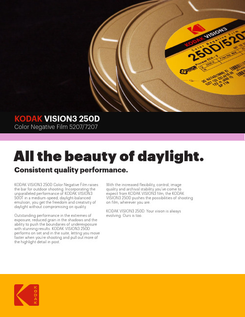
KODAK VISION3 250DAll the beauty of daylight. Consistent quality performance.KODAK VISION3 250D Color Negative Film raises the bar for outdoor shooting. Incorporating the unparalleled performance of KODAK VISION3 500T in a medium-speed, daylight-balanced emulsion, you get the freedom and creativity of daylight without compromising on quality. Outstanding performance in the extremes of exposure, reduced grain in the shadows and the ability to push the boundaries of underexposure with stunning results. KODAK VISION3 250D performs on set and in the suite, letting you move faster when you’re shooting and pull out more of the highlight detail in post.With the increased flexibility, control, image quality and archival stability you’ve come to expect from KODAK VISION3 film, the KODAK VISION3 250D pushes the possibilities of shooting on film, wherever you are.KODAK VISION3 250D. Your vision is always evolving. Ours is too.Daylight(5500 K)None250 Metal Halide None250H.M.I.None250 KINO FLO KF55None250Tungsten (3000 K)WRATTEN2 OpticalNo. 80A64Tungsten (3200 K)WRATTEN2 OpticalNo. 80A64KINO FLO KF29WRATTEN2 OpticalNo. 80A64KINO FLO KF32WRATTEN2 OpticalNo. 80A64Fluorescent, Warm White †WRATTEN2 CC20M+ CC05R160Fluorescent,Cool White †WRATTEN2 CC40R160* These are approximate corrections only.† T hese are starting-point recommendations for trial exposures.If the kind of lamp is unknown, a KODAK WRATTEN2 ColorCompensating Filter CC20M + CC10B can be used with anexposure index (EI) of 160.BaseAcetate safety base with rem-jetbacking.Darkroom RecommendationsDo not use a safelight. Handleunprocessed film in total darkness.ProcessingECN-2StorageStore unexposed film at 13°C (55°F) orlower. For storage of unexposed filmlonger than 6 months, store at –18°C(0°F). Process film promptly.Exposure IndexDaylight (5500K)—250; Tungsten—64(with KODAK WRATTEN 2 Gelatin FilterNo. 80A)Laboratory Aim DensityTime negative originals relative toLaboratory Aim Density (LAD) Control Filmsupplied by Eastman Kodak Company.More information about LAD and DigitalLAD is available online at www.kodak.com/go/LADColor BalanceThis film is balanced for exposure withdaylight illumination (5500K). For otherlight sources, use the correction filtersin the table to the right.ReciprocityNo filter corrections or exposureadjustments for exposure times from1/1000 of a second to 1 second. Ifyour exposure is in the 10-secondrange, increase exposure 1 stop anduse a KODAK WRATTEN 2 Filter, ColorCompensating CC10R.IdentificationAfter processing, the Kodak internalproduct code symbol (EN), productcode number 5207, emulsion/rollnumber identification, and EASTMANKEYKODE Numbers are visible along thelength of the film.GrainThe perception of graininess of anyfilm depends on scene content,complexity, color, and density. InKODAK VISION3 250D Color NegativeFilm 5207/7207, the measuredgranularity is exceptionally low.SharpnessThe perceived sharpness of any filmdepends on various components ofthe motion picture production system.Camera and projector lenses, filmprinters, and other factors play a role,but the specific sharpness of a filmcan be measured and charted in theModulation Transfer Curve.KODAK VISION3 250DColor Negative Film 5207/7207STANDARD PRODUCTS AVAILABLE*CAT NO.Format andSpecification No. Length in meters(feet)Core DescriptionPerforations/PitchMetric (imperial)MOQ FTO**743718965 mm SP332122 (400)P Emulsion In KS-4740 (KS-1866)1 106512765 mm SP332152 (500)P Emulsion In KS-4740 (KS-1866)15Yes 122763665 mm SP332305 (1000)P Emulsion In KS-4740 (KS-1866)15Yes 100178335 mm SP71861 (200)U Emulsion In BH-4740 (BH-1866)30Yes 898690335 mm SP718122 (400)U Emulsion In BH-4740 (BH-1866)1 890393235 mm SP718305 (1000)U Emulsion In BH-4740 (BH-1866)1138268816 mm SP45530 (100)R-90 100-ft. spool Emulsion InWinding B1R-7605 (1R-2994)1867626416 mm SP457122 (400)T Emulsion InWinding B1R-7605 (1R-2994)1* Availability may vary by location. Contact your local Kodak representative for additional information.** This product is available as Finish-to-Order (FTO) in various other standard roll lengths and formats. Sold only in specific minimum order quantities or multiples of the minimum order quantities; non-returnable; US and Canada delivery time of 3 weeks from receipt of purchase order. Other restrictions may apply.Notice: While the data presented are typical of production coatings, they do not represent standards that must be met by Kodak.Varying storage, exposure, and processing conditions will affect results. The company reserves the right to change and improve product characteristics at any time.©Kodak, 2018. Kodak, Eastman, Keykode, and Vision, Wratten are trademarks. H-1-5207 180929For more information: /go/motion Sales offices: /go/salesoffices Lab directory: /go/findlab。
Arecont Vision SurroundVideo Omni安装说明书

Surround Video® OmniINSTALLATION MANUALAV12176DN-NLAV12176DN-28AV12176DN-08AV20175DN-NLAV20175DN-28AV20175DN-08SurroundVideo® Omni InstallationContentsPackage Contents (3)Warranty Information (4)Installation Overview (5)Installation Overview (with Adapter Plate) (6)Camera Setup (7)Camera Adjustment (8)Camera Alignment (10)Installation (11)Changing the Lens (13)Accessing the Digital Input and Output Connector (14)Digital Input and Output (15)Auxiliary Power (16)LED Indicators (17)Installation Best Practice (19)Wall Mount Accessory (AV-WMJB) (21)Pendant Mount Accessory (AV-PMJB) (22)Troubleshooting (24)Page|**************************Package ContentsItem DescriptionMegaPixel Camera SurroundVideo® OmniMounting Kit Ceiling template3x Mounting Screws (#6x1” for wood or sheetmetal)3x Drywall/Masonry Mounting AnchorsCeiling GasketNetwork Patch CableSecurity Torx ToolAdapter plate (for drop ceiling)3x Mounting Screws ((#6x2” for adapter plate) Power Cable Aux Power CordI/O Cable Digital Input and Output AdapterArecont Vision CD Manual, Warranty, Installation SoftwareNotes:1.Camera Operating Temperature : -40°C (-40°F) to +50°C (122°F)2.Wiring methods shall be in accordance with the National Electrical Code/NFPA 70/ANSI, andwith all local codes and authorities having jurisdiction. Wiring should be UL Listed and/orRecognized wire suitable for the application.3.Always use hardware e.g. screws, anchors, bolts, locking nuts etc. which are compatible withmounting surface and of sufficient length and construction to insure a secure mount.4.For use in ducts, plenums and other air-handling areas, replace Auxiliary Cable provided withCMP, CL2P or CL3P type wires.Page|**************************Warranty Information3 Year Limited WarrantyARECONT VISION warrants to Purchaser (and only Purchaser) (the “Limited Warranty”), that: (a) each Product shall be freefrom material defects in material and workmanship for a period of thirty-six (36) months from the date of shipment (the“Warranty Period”); (b) during the Warranty Period, the Products will materially conform with the specification in the applicable documentation; (c) all licensed programs accompanying the Product (the “Licensed Programs”) will materially conform withapplicable specifications. Notwithstanding the preceding provisions, ARECONT VISION shall have no obligation orresponsibility with respect to any Product that (i) has been modified or altered without ARECONT VISION’s writtenauthorization; (ii) has not been used in accordance with applicable documentation; (iii) has been subjected to unusual stress,neglect, misuse, abuse, improper storage, testing or connection; or unauthorized repair; or (iv) is no longer covered under the Warranty Period. ARECONT VISION MAKE NO WARRANTIES OR CONDITIONS, EXPRESS, IMPLIED, STATUTORY OROTHERWISE, OTHER THAN THE EXPRESS LIMITED WARRANTIES MADE BY ARECONT VISION ABOVE, ANDARECONT VISION HEREBY SPECIFICALLY DISCLAIMS ALL OTHER EXPRESS, STATUTORY AND IMPLIEDWARRANTIES AND CONDITIONS, INCLUDING THE IMPLIED WARRANTIES OF MERCHANTABILITY, FITNESS FOR APARTICULAR PURPOSE, NON-INFRINGEMENT AND THE IMPLIED CONDITION OF SATISFACTORY QUALITY. ALLLICENSED PROGRAMS ARE LICENSED ON AN “AS IS” BASIS WITHOUT WARRANTY. ARECONT VISION DOES NOTWARRANT THAT (I) THE OPERATION OF THE PRODUCTS OR PARTS WILL BE UNINTERRUPTED OR ERROR FREE;(II) THE PRODUCTS OR PARTS AND DOCUMENTATION WILL MEET THE END USERS’ REQUIREMENTS; (III) THEPRODUCTS OR PARTS WILL OPERATE IN COMBINATIONS AND CONFIGURATIONS SELECTED BY THE END USER;OTHER THAN COMBINATIONS AND CONFIGURATIONS WITH PARTS OR OTHER PRODUCTS AUTHORIZED BYARECONT VISION OR (IV) THAT ALL LICENSED PROGRAM ERRORS WILL BE CORRECTED.For RMA and Advance Replacement information visit Page|**************************Page|**************************Installation OverviewGasket(Not required for indoor)CeilingDome CoverCaptive FastenersCamera HousingMounting ScrewsNPT Port GasketCamera Gimbals (4X)Page|**************************Installation Overview (with Adapter Plate)Drop CeilingDome CoverCaptive FastenersCamera HousingMounting ScrewsNPT Port GasketCamera Gimbals (4X)Adapter Plate** Need to bend tethering eyelet before usingGasket(Not required for indoor)Tethering Eyelet (Bend by hand)Page|**************************Camera SetupThe SurroundVideo® Omni is user configurable. Each individual sensor can be positioned in a variety of ways.Below are some example configurations (top left to bottom right) 1. 270° 2. Straight Line 3. 360° or Hallway 4.180° or Panoramic 5. Random Example 6. Random Example.Prior to installing the camera, thought should be given to the sensor positions. It is always easier to makeadjustments before the camera is installed.TechTipPage|**************************Camera AdjustmentTo position a sensor simply loosen the captive fastener to release the camera assembly from the track plate.Next, position the camera in the desired location on the track plate. Screw holes around the circumference are spaced in 5 degree increments. Note the arrows marked at 45 degrees as reference points.Captive FastenerTrack Plate5° 0°10° 45° Reference Mark#4-40 ScrewPage|**************************Sensor numbering is indicated on the track plate. The number on the track plate corresponds to the sensor number in the camera software.Sensor positioning and alignment should be considered before camera installation. It is easier to adjust the individual camera positions before the camera is installed into a ceiling. The three slots in the track plate provide additional adjustment of the camera after installation. Simply loosen the three screws to rotate the plate then tighten the three screws after alignment. This feature is most useful for repositioning the cameras mounted to the center locations after camera installation.Tech TipPage|***************************Camera AlignmentAlignment of the individual cameras is critical to setup. The individual cameras when placed on thecircumference of the track must be in a counterclockwise sequence to create proper alignment when viewing the camera.Sensor 1Sensor 2Sensor 3Sensor 4Sensor 1Sensor 2Sensor 3Sensor 4CounterclockwiseCounterclockwiseTech TipInstallation1.Wiring methods shall be in accordance with the National Electrical Code/NFPA 70/ANSI, and with alllocal codes and authorities having jurisdiction. Wiring should be UL Listed and/or Recognized wiresuitable for the application.2.Operating Temperature -40°C (-40°F) to +50°C (122°F)3.Always use hardware e.g. screws, anchors, bolts, locking nuts etc. which are compatible with mountingsurface and of sufficient length and construction to insure a secure mount4.Visit / and check to ensure your camera has the most current firmware.5.If using the NPT port always use Teflon tape around threads to ensure proper sealing.6.If using adapter plate, bend tethering eyelet up 90° by hand.7.After plugging in the network cable check that the indicator LED’s are indicating the desired conditions(see LED Indicator table).e Arecont Vision software AV200 located on the CD or available for download at our website() for camera discovery and setup (see Instruction Manual located on CD oravailable on our website).9.Adjust the individual cameras to obtain the desired fields of view (see Focusing Instructions).10.Lens may be further secured by tightening the lens lock screw using Phillips head screwdriver.11.Install the Dome Cover by aligning the captive fasteners with the mating threaded holes on the camerahousing.12.When mounting the Dome Cover to the Camera Housing ensure that the gasket is properly seating andnot folded. Failure to do so may result in water and dust ingress.Best Practice TipsWhen mounting to vertical surface it is best to use the Wall Mount Accessory which includes a Junction Box.For outdoor use it is always best to properly seal the product using caulk around the edges to prevent water ingress from mounting to porous or uneven surfaces.Use Teflon tape on threaded interfaces.Page|***************************Page|***************************Focusing the Cameras1. Open a live view of the camera from your web browser or the AV Software provided (AV200).2. Loosen the lens lock screw using a phillips head screwdriver (if necessary). Only do so if lens seems verytight when turning. Lock screw should be tightened enough to provide some friction against the lens to avoid focusing problems.3. Manually rotate the lens to adjust the focus until the desired image is obtained.4. For some lenses a focus shift will occur once the bubble is in place. Hold the bubble up to the lens whenfocusing to account for the focus shift or see the “Focusing Alternate Lenses” section below for further instruction.5. Retighten the lock screw if necessary.6. Install the Dome Cover by aligning the captive fasteners with the mating threaded holes on the camerahousing.7. When mounting the Dome Cover to the Camera Housing ensure that the gasket is properly seating andnot folded. Failure to do so may result in water and dust ingress.Tech TipPage|***************************Changing the Lens1. Remove the Dome Cover by loosening the captive fasteners as shown in Image 1.2. Loosen the lens lock screw using a phillips head screwdriver (if necessary) as shown in Image 2. Only doso if lens seems very tight when turning.3. Manually unscrew the lens, this may take several seconds as shown in Image 3.4. Replace lens as shown in Image 4.5. Retighten the lock screw if necessary as shown in Image 5.6. Reinstall Dome Cover per instructions outlined above as shown in Image 6.Image 1 Image 2 Image 3Image 4 Image 5 Image 6Page|***************************Focusing Alternate LensesWhen focusing the 6mm, 8mm, 12mm or 16mm lens options you will encounter a focus shift when using the bubble. To account for this follow these steps:1. Focus the camera without the bubble.2. Rotate the lens per the chart below. The rotation will account for most of the focus shift.3. Put cover with bubble on. You should be close to being focused.4. Remove cover and rotate a couple degrees at a time in either direction until you gain the desired image.Example: Using a 16mm lens you will focus the lens without the bubble until you get the desired image. Rotate the lens almost ¾ of a turn (250°). Put the bubble on and view the image. It should be almost in focus. Remove the bubble and rotate a degree or two in one direction and view the image with the bubble on. Depending on the image you may need to adjust in the opposite direction or continue in the same direction until the desired image is obtained.Accessing the Digital Input and Output ConnectorThe 4 position connector inside camera housing located on the main circuit board used for I/O can be accessed by removing the track plate. Simply loosen the three screws indicated in the image below, lift the track plate and find the connector. The approximate connector position is indicated by the red circle below.LensRotation MPM16.0 16mm <3/4 CCW 250° MPM12.0 12mm 1/4 CCW 90° MPM8.0 8mm >1/8 CCW 60° MPM6.06mm1/8 CCW45°Tech TipDigital Input and OutputUse 4 position connector inside camera housing to interface with Digital I/O.DIGITAL I/OBLACK IN -WHITE IN +YELLOW OUT -ORANGE OUT + Electrical Characteristics MIN MAXInput Voltage (V) (Measured between + and – terminals) ON 2.9 6.3 OFF 0 1.3Output Current (mA) (Measured between + and – terminals) Applied Voltage Range :0-80V ON - 50 OFF - 0.1NOTE: Both the input and the output are electrically isolated from the rest of the camera’s electricalcircuitry via general-purpose photo couplers. The input is additionally protected with a serial 250 Ohmresistor and a debouncing circuit. Duration of any input signal should be at least 5ms to comply with the requirements of the debouncing circuit.Page|***************************Auxiliary PowerIf the camera is powered by a separate outside AC or DC power source, run the supplied power cable throughthe access hole on the camera housing and connect the power cable to the 2-position connector on the maincamera board. The approximate location of the 2-position connector is circled in red below.NOTE: Wiring methods shall be in accordance with the National Electrical Code/NFPA 70/ANSI, and with alllocal codes and authorities having jurisdiction. Wiring should be UL Listed and/or Recognized wire suitable for the application.For use in ducts, plenums and other air-handling areas, replace Auxiliary Cable provided with CMP, CL2P orCL3P type wires.Page|***************************LED IndicatorsLED Status DescriptionYellow Flashing Link has beenestablished.Solid Normal Operation.None No connection.Green Flashing Camera has beenaccessed. Normaloperation.Solid N/ANone No Connection. Page|***************************SupportArecont Vision FAQ Page Located at Check the following before you call:Restore camera to factory default with AV100, AV200 or the camera webpage.Upgrade to the latest firmware by visiting .Isolate the camera on a dedicated network and test with AV100 or AV200.Swap the “troubled” camera with a known good camera to see if the problem follows the camera or stays at the location.Contact Arecont Vision Technical Support one of three ways:Online Portal : Phone : 1.818.937.0700 (option #1)Email:*************************Page|***************************Surround Video® OmniInstallation Best PracticeNoBegin InstallationWind Vinyl electricaltape on all cablesconnectionsAdding Teflon thread sealingtape to all male threadsDoes conduit pipe gothrough the wall?Make sure position of conduit hole is at the lower sideforming a “drip loop” below the camera using ¾”galvanized or flex conduit and appropriate fittingsConnect ¾” NPT conduitpipe to junction box adapterYesTighten all camerascrews and ¾”NPT plugsCaulk the perimeter ofthe mounting areaConduct periodic inspections of the installation.Rust on the metal parts or screws may result indamage to cameraEnd Installation Not Recommended!Not Recommended!Recommended!Recommended!Arecont Vision Surround Video ® Omni Installation ManualPage|***************************Surround Video ® OmniCamera Discovery, Setup, and ConfigurationFor camera discovery and setup please use Arecont Vision software AV200 which you can find on the CD included with your camera or at:/softwares.phpThe user manual for the AV200 software is included on the CD and is also located on our website.To configure the camera use either the AV200 software or the web interface utility. The web interface can be accessed by typing the camera IP address into your web browser or by clicking on the web interface button in AV200. The user manual for our web interface is included on the CD and is also located on our website.Wall Mount Accessory (AV-WMJB)Gasket-1.5” NPTGasketInstallation Notes:1.4x mounting screws are #10x1” wood or she et metal screws (4x mount anchorsalso included).2.Always ensure gaskets are properly seated.e Teflon tape on threaded interfaces.Page|***************************Page|***************************Pendant Mount Accessory (AV-PMJB)Installation Notes:1. 4x mounting screws are #10x1” wood or sheet metal screws (4x mount anchors also included).2. Always ensure gaskets are properly seated.3. Use Teflon tape on threaded interfaces.GasketGasket-1.5” NPTMount Template Page|***************************TroubleshootingBefore troubleshooting, please visit / and check to ensure your camera has the most current and correct firmware version.Problem Possible Cause SolutionReflections on the image Lenses face the bubble crease,and the angle between Lensesand bubble is not perpendicular.X:Make lenses face bubbleperpendicularly and avoidfacing the bubble creaseO:Lens facing down the bubble isnot tilted up 90°.X:Ensure lens is tilted up 90°when facing down the bubble.O:Page|***************************Image quality problemsorDay/Night switch failure Day/Night switch failure causedby turning lenses backwardX:Ensure lens is orientedcorrectlyO:Captive FastenerPage|***************************Contact Arecont Vision Technical Support one of three ways:Online Portal : Phone : 1.818.937.0700 (option #1)Email:*************************Page|***************************。
安防监控产品分类汇总-中英文
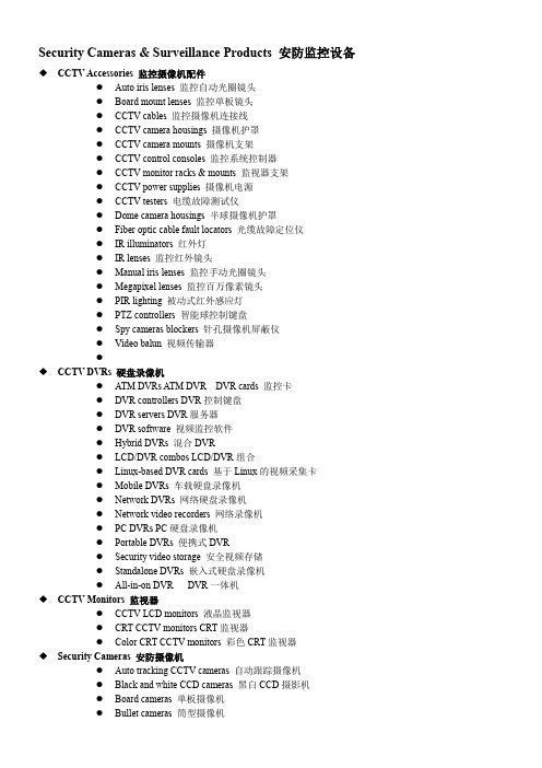
Security Cameras & Surveillance Products 安防监控设备◆CCTV Accessories 监控摄像机配件●Auto iris lenses 监控自动光圈镜头●Board mount lenses 监控单板镜头●CCTV cables 监控摄像机连接线●CCTV camera housings 摄像机护罩●CCTV camera mounts 摄像机支架●CCTV control consoles 监控系统控制器●CCTV monitor racks & mounts 监视器支架●CCTV power supplies 摄像机电源●CCTV testers 电缆故障测试仪●Dome camera housings 半球摄像机护罩●Fiber optic cable fault locators 光缆故障定位仪●IR illuminators 红外灯●IR lenses 监控红外镜头●Manual iris lenses 监控手动光圈镜头●Megapixel lenses 监控百万像素镜头●PIR lighting 被动式红外感应灯●PTZ controllers 智能球控制键盘●Spy cameras blockers 针孔摄像机屏蔽仪●Video balun 视频传输器●◆CCTV DVRs 硬盘录像机●ATM DVRs A TM DVR DVR cards 监控卡●DVR controllers DVR控制键盘●DVR servers DVR服务器●DVR software 视频监控软件●Hybrid DVRs 混合DVR●LCD/DVR combos LCD/DVR组合●Linux-based DVR cards 基于Linux的视频采集卡●Mobile DVRs 车载硬盘录像机●Network DVRs 网络硬盘录像机●Network video recorders 网络录像机●PC DVRs PC硬盘录像机●Portable DVRs 便携式DVR●Security video storage 安全视频存储●Standalone DVRs 嵌入式硬盘录像机●All-in-on DVR DVR一体机◆CCTV Monitors 监视器●CCTV LCD monitors 液晶监视器●CRT CCTV monitors CRT监视器●Color CRT CCTV monitors 彩色CRT监视器◆Security Cameras 安防摄像机●Auto tracking CCTV cameras 自动跟踪摄像机●Black and white CCD cameras 黑白CCD摄影机●Board cameras 单板摄像机●Bullet cameras 筒型摄像机●CCD dome cameras CCD摄像机●CCTV CMOS cameras CMOS监控摄像机●CCTV box cameras 枪式摄像机●CCTV digital CCD cameras 数码CCD摄像机●CCTV water-resistant cameras 防水监控摄像机●CCTV zoom cameras 变焦摄像机(All-in-one Camera 一体机)●Color CCD cameras 彩色CCD摄像机●Color IR day/night cameras 日夜两用彩色半球摄像机●Dummy cameras 仿真监控摄像机●Dynamic noise reduction cameras 动态降噪相机●Fixed dome cameras 固定半球摄像机●Hidden cameras 隐蔽摄像机●IP box cameras 网络超低照度摄像机●IP speed dome cameras 网络高速球摄像机●IR and day/night cameras 日夜两用半球摄像机●IR speed dome cameras 红外高速球摄像机●Long-range IR cameras 长距离红外摄像机●Megapixel surveillance cameras 百万像素监视摄像机●Metal dome cameras 金属半球摄像机●Mini cameras 迷你摄像机●Network cameras 网络摄像机●Night-vision cameras 夜视摄像机●Outdoor speed dome cameras 室外智能高速球●PTZ cameras 智能球●Pin-hole cameras 针孔摄影机●Speed dome cameras 智能高速球●Thermal imaging cameras 热成像摄像机●Vandal-proof CCTV cameras 防爆监控摄像机●Vandal-proof IR cameras 防爆红外摄像机●Vandal-proof speed cameras 防爆高速摄像机●Varifocal dome cameras 变焦半球摄像机●Weatherproof IR cameras 防水红外摄像机●Wide dynamic range cameras 超宽动态摄像机●Wired IP cameras 有线网络摄像机●Wireless CCTV cameras 无线监控摄像机●Wireless IP cameras 无线网络摄像机◆Spy Security Cameras 针孔摄像机●Camera sunglasses 眼镜摄像机●Hidden camera clocks 钟表式摄像机●Smoke detector cameras 烟感型摄像机●Spy camera pens 针孔录像笔●Spy camera watches 手表针孔摄像机◆Surveillance Systems 监控系统●3GPP surveillance systems 3GPP流媒体监控系统●Automatic number plate recognition 车牌自动识别系统●CCTV camera modules 监控摄像机模块●CCTV monitors with integrated quad/switcher 集成监视器●CCTV receivers & transmitters 监控收发器●CCTV switchers & multiplexers 画面处理器●Counter surveillance equipment 反监控设备●Integrated CCTV monitor/camera systems 集成监控系统●Quad processors 四画面分割器●Remote video monitoring systems 视频远程监控系统●Security management software 安全管理软件●Security matrix systems 安全矩阵系统●Surveillance servers 监控服务器●Traffic surveillance systems 交通监控系统●Video analytics 影像分析●Video enhancement equipment 影像控制设备Safety & Emergency Systems 防盗安全系统◆Emergency Alert Systems 紧急警报系统●Emergency broadcast systems 紧急广播系统●Emergency phones 紧急电话●Freeze & temperature alarms 温度报警器●Panic buttons 紧急按钮◆Safety & Environmental Monitoring Products 安防监控产品●Earthquake detectors 地震仪●Explosives detectors 炸药探测器●Flame detectors 火焰探测器●Ground search metal detectors 地下金属探测仪●Handheld metal detectors 手持金属探测器Access Control Products 门禁产品●Access Control Readers & Input Devices 门禁读卡器/输入设备◆Access control keypads 门禁机◆IC card readers IC读卡器◆Magnetic card readers 磁卡读卡器◆Magnetic cards 磁卡◆Proximity-card readers 感应读卡器◆Security smart cards 安全智能卡◆Smart card readers 智能卡读卡器◆Time recorders 考勤机◆USB smart card readers USB智能卡读卡器◆Wiegand card readers 韦根读卡器●Biometric Products 生物识别产品◆Combination biometric access control products 生物识别门禁系统◆Facial recognition systems 人脸识别系统◆Fingerprint access control 指纹门禁◆Fingerprint door locks 指纹门锁◆Hand geometry recognition systems 手几何识别系统◆Iris recognition systems 虹膜识别系统◆Signature verification devices 确认签字设备◆Vein recognition systems 静脉识别系统◆V oice recognition systems 声音识别系统Solar & Energy Saving Products 太阳能及节能产品●Energy-efficient Lighting & Accessories 节能灯具及附件◆Energy-efficient Light Bulbs & Tubes 节能灯泡及灯管◆CFLs 节能灯◆Candle CFLs 烛形节能灯◆Dimmable CFLs 调光节能灯◆Electrodeless discharge lamps 无极灯◆Fluorescent tubes 荧光灯管◆Globe CFLs 球形节能灯◆Halogen bulbs 卤素灯泡◆Metal halide bulbs 金卤灯◆Reflector CFLs 反射节能灯◆Sodium bulbs 钠灯◆Spiral CFLs 螺旋节能灯◆U-shaped CFLs U 型节能灯●Energy-efficient Lighting Fixtures & Accessories 节能型照明器材及配件◆Dimmers 调光器◆Fluorescent lights 荧光灯◆Industrial HID light fixtures 工业氙气灯◆LED lighting controllers LED灯控制器◆Motion sensor light switches 感应开关◆Motion sensor lights 感应灯◆Power savers 节电设备◆Programmable timers 可编程定时器●LED Bulbs & Tubes LED灯泡及灯管◆Dimmable LED bulbs 可调光LED灯泡◆Dimmable LED tubes 可调光LED灯管◆E14 LED bulbs E14 LED灯◆E27 LED bulbs E27 LED灯◆GU10 LED bulbs GU10 LED灯◆LED bulbs LED灯泡◆ED candle bulbs LED蜡烛灯◆LED globe bulbs LED球泡◆LED spotlight bulbs LED聚光灯◆LED tubes LED灯管◆MR11 LED bulbs MR11 LED灯◆MR16 LED bulbs LED灯杯◆T10 LED tubes T10 LED灯管◆T5 LED tubes T5 LED灯管◆T8 LED tubes T8 LED灯管●LED Lighting Fixtures LED照明器材◆LED cabinet lights LED橱柜灯◆LED ceiling lights LED吸顶灯◆LED ceiling spotlights LED吸顶射灯◆LED column lights LED柱灯◆LED downlights LED筒灯◆LED emergency lights LED 应急灯◆LED exit signs LED出口指示灯◆LED floodlights LED泛光灯◆LED grid lights LED格栅灯◆LED ground lights LED埋地灯◆LED grow lights LED植物生长灯◆LED high bay lights LED工矿灯◆LED light fixtures LED灯具◆LED mirror lights LED镜灯◆LED mood lights 情境灯◆LED panel lights LED面板灯◆LED recessed lights LED嵌灯◆LED rope lights LED灯带◆LED street lights LED路灯◆LED string lights LED灯串◆LED tunnel lights LED隧道灯◆LED underwater lights LED水底灯◆LED wall washers LED洗墙灯◆LED work lights LED工作灯◆。
Mitutoyo QV Active Vision测量系统说明书
V i s i o n M e a s u r i n g S y s t e mA fully featured, automated vision measurement system featuring a space saving ergonomic designHigh SpeedHigh AccuracyHigh ThroughputAim Higher with Mitutoyo's QV ActiveVision Measurement SystemsHigh EfficiencyAutomatic edge detectionThe "automatic edge detection" function provides superiorreproducibility of measurements regardless of the skill level ofthe operator.Image auto focusMultiple methods of "image auto focus" allows high-speed /high-accuracy height measurements of 3D featuresPattern searchThe "pattern search" function automatically recognizes imagepatterns to create part alignment and feature measurement.Manual toolBy applying a"manual tool" sequence to a CNC measurementroutine, automatic measurement sequencing can be performed.This "One-Click" method reduces the need for fixtures as thezero point is created anywhere on the part, fixture or stage.Easy to use measurement for multiplework p ieces and repetitive feature arraysAutomatic measurement routines areavailable with either a click of a button orwith image recognitionBox tool Circle tool Arc toolSurface focus tool Multipoint auto focus toolNormal position Position is automatically compensated Intelligent and Automated FeatureProcess i ng Tools allow unattendedinspectionSuperior Flexibility with Color Zoom Optical System Interchangeable objective lens zoom unitThe newly designed 7:1 ratio zoom unit and interchangeable objectives provide 13x – 183x on-screen optical magnification.From wide field of view measurement to micro-measurement0.5X2X3.5X0.75X3X5.25X1X4X7XObjective 1X(option)Objective 1.5X(Standard accessory)Objective 2X(option)Exceptional objective working distance handlesthe tallest part measurement requirementsBest in class working distanceA working distance of 74mm* reduces the risk of damaging the objectiveor workpiece by accidental collision.* Using the 1X objective.Z-objective 1.5xZ-objective 2xMaster ball (option)MCR20 (option)One-click tool for feature measurementsSelect the element type, and with just one click on an edge, a high-accuracy measurement is taken regardless of the proficiency level of the operator. The embedded outlier removal filter automatically excludes bad data caused by burrs and dust.QVNavigatorALL skill levels can easily run and repeat identical measurement routines. An image or diagram of the workpiece can be registered as an icon in an automatic measurement program, enabling the tar g et program to be quickly executed. QVEasyEditorA teaching method is adopted in which programs are automatically recorded while measurement is performed. The insertion, revision, addition, and deletion of the part program can be performed easily using the tree-structure display. Also, execution of only a certain portion of the program after editing can be performed for the purpose of confirmation. Power-user-oriented QVBasicEditor is also available.QVGraphicsA simple operation, just clicking a measurement graphic element shown in the graphic window, enables coordinate creation/ change, combination arithmetic operations, and geometric deviation illustration of roundness, flatness, and more.A useful function is automatic creation of a measurement program just by dragging a pitch measurement element.Easy-to-operate across all skill levels Easily created measuring macros with walk through vitalization The embedded intelligence of Easy Editor makes programing and editing simplerFull featured 2D and 3D graphical results moduleallows the operator to perform visual analysisUser-specific macro creation functionRegistration example of an automaticmeasurement programMove the mouse to the edge and click once.Geometric deviation of a plane surfaceMeasurement result graphicGeometric deviation of a circular featureEasy-to-read tree-structure viewExecutes high-accuracy multi-point measurementand removes the outlierSoftware that is simple to use, yet advanced when you need itZoom lensUsing Mitutoyo's proprietary high-quality zoom system andobjective lenses the feature field of view is expanded. Multipleobjectives allow increased operator image viewing flexibility. High-definition color cameraMeasurement and observation is performed using high-qualityand high-definition images which prevents operator fatigueeven over long periods of observation.Superior Lighting with automated feature illuminationTransmitted, co-axial and 4-quadrant ring lighting is provided soworkpiece illumination can be set independently from thefront, rear, right and left directions. This enables more reliablemeasurement by enhancing the sharpness of the edge of thefeature to be measured.Wide Field of view allows more imageview, ensuring easier feature locating Large screen format with high-definitioncolor images reduces eye fatigueClear edges ensure reliable measurementStandard layout Manual-measurement-preferential layoutMagnification of 0.5x10.8mmOptional Software Tools2D Profile Analysis Software FORMTRACEPAK-APThis is contour analysis software that can perform sophisticated analyses such as design value verification (Toleranced Data Sets from Feature Creation) and shape analysis (2-D Profile) with data obtained via QVPAK measurement tools.Contour tolerancing functionShape analysis• Creating design dataCAD data conversion, master work conversion, function assignment, text file conversion, creating spherical surface design data • Verification of design dataVerification of normal line direction, axial direction, and best fit• Result displayResult list, error diagram, error development diagram, error coordinatevalues, analysis results• Analysis items: Point measurement, line measurement, circle measure-ment, distance measurement, intersection point measurement, angle measurement, origin point setting, axis rotation• Arithmetic operation items: Maximum value, minimum value, mean value, standard deviation, areaReport creation functionOther functions• Measurement results, error diagram, error development diagram• Record/execution of analysis procedure• CSV format output, text output, DXF/IGES format output • Fairing• Quadratic curve approximating function • Pseudo roughness analysis functionExample of design value verificationMeasurement example of lines, space, and thick-ness of conductive portion on PCBTwo-dimensional CAD drawings (DXF or IGES format) can be imported to QV Graphics.The measurement results can also be converted to CAD drawings. The design value of each measurement item will be automatically entered. Because the current position can be easily found using graphics, the stage can be quickly moved to an arbitrary position on a CAD drawing which results in im-proving operability during the measurement. (Refer to QV Graphics on P6.)CAD Program Software Modules QV-CAD I/F, EASYPAG, QV 3DCAD onlineWorkpieces aligned on a jig.QV Parts manager windowIt is possible to measure It is possible to measure various types of Part Program Management Software QVPartManagerQV PartManager is part program execution management software for multiple workpieces arranged on the measuring stage. A part program can be executed and managed for various kinds of workpieces and workpieces not arranged in an orderly manner.Integrated solutions modules QVEioQVEio is a client application software for external control. It provides three functions: QVEio-PLC, QVEio-PC, and QVEio-Signal. QVEio-PLC is a software package that can inform a user of the state of an external execution command via a PLC. As an example, this can be used to control robots. QVEio-PC allows control of the Quick Vision machine though an external PC connected via RS-232C, and it also exports results and error states. QVEio-Signal outputs the operating status of the Quick Vision machine. This is best suited for displaying the operating status to a signal tower, for example.Data collection/statistics MeasurLink ®This is a process management program that can perform statistical processing control (SPC) based on measurement results.Display of the control chart in real time enables early detection of machining abnormality which is effective in preventing the generation of defective products.*2 Does not apply for unbalanced or concentrated loads.each magnification, and correct optical axis offset.External dimensionsQuick Vision Active 202Unit: Inch(mm)Unit: Inch(mm)30.19”(767)12%space savingspace saving30%Quick Vision Active 202Our conventional model (ELF )Quick Vision Active 404Our conventional model (QV404)World's top level of global networkExcellent reliabilityMitutoyo has expanded its market all over the world since the establishment of the first overseas sales company, MTI Corporation (currently Mitutoyo America Corporation) in the USA in 1963.At present, we have R&D, manufacturing, sales, and technical service bases in 29 countries with an agency network connecting over 80 countries.Mitutoyo Europe GmbH Mitutoyo (UK) L.td.Mitutoyo France S.A.R.L Mitutoyo Italiana S.R.L.Mitutoyo Asia Pacific Pte.Ltd. Regional Headquarters Mitutoyo Measuring Instru-ments (Suzhou) Co., Ltd.Mitutoyo America Corpo-ration Head OfficeMITUTOYO SUL AMERICANALtda. Factory (Suzano)Headquarters■Local Sales Office■Research andCompany Headquartersin Kawasaki, Japan National Institute ofStandards and Technology(NIST)Working standardSecondary standardSecondary standardPrimary National StandardMitutoyo America CorporationA2LA AccreditedScope of Accreditation to ISO/IEC17025:2005 & ANSI/NCSL Z540-1-1994 &ANSI/NCSL Z540.3-2006Mitutoyo Utsunomiya Measurement StandardsCalibration Center633nm Practical Stabilized He-Ne LaserInterferometer (for standard scale)Vision Measuring System (measuring accuracy)Mitutoyo Kawasaki plantWorking standardSensor Systems Test Equipmentand Seismometers Digital Scale and DRO SystemsSmall Tool Instrumentsand Data Managementbasis.Mitutoyo America CorporationOne Number to Serve You Better1-888-MITUTOYO (1-888-648-8869)M3 Solution Centers:Aurora, Illinois (Headquarters)Boston, MassachusettsCharlotte, North CarolinaCincinnati, OhioDetroit, MichiganLos Angeles, CaliforniaBirmingham, AlabamaSeattle, WashingtonHouston, Texas5M 0418-02 • Printed in USA • April 2018©218MitutoyoAmericaCorporationFind additional product literatureand our product catalogNote: All inform ation regarding our products, and in particular the illustrations, drawings, dim ensional and performancedata contained in this printed matter as well as other technical data are to be regarded as approximate average values. Wetherefore reserve the right to make changes to the corresponding designs. The stated standards, similar technical regulations,descriptions and illustrations of the products were valid at the time of printing. In addition, the latest applicable version of ourGeneral Trading Conditions will apply. Only quotations submitted by ourselves may be regarded as definitive. Specificationsare subject to change without notice.Mitutoyo products are subject to US Export Administration Regulations (EAR). Re-export or relocation of our products mayrequire prior approval by an appropriate governing authority.Trademarks and RegistrationsDesignations used by companies to distinguish their products are often claimed as trademarks. In all instances where MitutoyoAm erica Corporation is aware of a claim, the product nam es appear in initial capital or all capital letters. The appropriatecompanies should be contacted for more complete trademark and registration information.。
DS-2CD6D44G1H-IZS 4方向多传感器网络摄像头说明书
DS-2CD6D44G1H-IZS 4-Directional Multisensor Network Camera
4 adjustable lenses in one camera cover up to 360° field of view, ensuring no blind area monitoring and the monitoring tilt angle can be adjusted Each lens up to 4 MP, capturing clear images, and more details can be displayed on video wall
Clear imaging against strong back light due to 120 dB true WDR technology Water and dust resistant (IP67) and vandal proof (IK10) 3D DNR technology delivers clean and sharp images Audio and alarm interface available Specification Camera Image Sensor 1/3" Progressive Scan CMOS Max. Resolution 2688 × 1520
Min. Illumination Color: 0.005 Lux @ (F1.2, AGC ON),B/W: 0.002 Lux @ (F1.2, AGC ON),B/W: 0 Lux with IR Shutter Time 1 s to 1/100,000 s Day & Night IR cut filter Angle Adjustment Pan: -60° to 60°,tilt: 10° to 90°,rotate: 0° to 350° Lens Lens Type Varifocal lens, motorized lens, 2.8 to 12 mm
camera学习入门指南
camera学习⼊门指南等待补充。
1.背景介绍近年来,随着消费电⼦领域市场的快速增长,如安防、图像等领域,camera市场得到了快速发展。
智能⼿机这⼏年以拍照作为主打卖点,带动了camera(CCM)出货。
具体可以看电⼦⾏业分析或者券商研报⾏业分析,⽐如下⾯两份。
在招聘⽹站上搜索camera,可以看到,多为⼿机⼚商、智能硬件和汽车安防相关⾏业,包括tuning、效果、系统、性能功耗、测试等,其中camera tuning的岗位是最多的。
绝⼤多数产品⽅案系统都是使⽤Android操作系统⽅案,所以需要对Android有⼀定了解。
以前camera tuning⼯作是由算法⼯程师完成,后⾯随着⽤户对图像质量要求越来越⾼。
ISP处理器出现和流⾏催⽣很多tuning的⼯作。
基础知识:光学基本概念、camera基础知识:涉及硬件模组、软件架构等,linux驱动开发基本知识。
2.camera基础篇camera和光学知识和摄影知识密切相关。
2.1.光学知识成像原理:视场⾓FOV(Field of View):包括HFOV(⽔平), VFOV(垂直),DFOV(对⾓)Focal Length:焦距EFL(Effective Focal Length)有效焦距、Fno(Aperture Value对应的Focal number)光圈数值,如F2.8,为光圈“系数”,简称为F值。
Fno = EFL/D(光圈直径)RGB(red green blue),光学三原⾊。
⾃然界中⾁眼所能看到的任何⾊彩都可以由这三种⾊彩混合叠加⽽成,因此也称为加⾊模式。
YUV(全称英⽂真没找到),是编译true-color颜⾊空间(color space)的种类,Y'UV, YUV, YCbCr,YPbPr等专有名词都可以称为YUV,彼此有重叠。
Y”表⽰明亮度(Luminance或Luma),也就是灰阶值,“U”和“V”表⽰的则是⾊度(Chrominance或Chroma)。
KONICA AUTO-REFLEX 35mm 电子眼相机说明书
P7
PRINTED IN u, s .....
PRICE 702-120 Auto -Reflex with f/l.4 Hexanon lens, camera strap and shoulder
pad, and flash shoe . .
. . . . . . . . . . . . . . . . . . . . . . .. $299.95
705-127 Extension Bellows /I high-quality single'rail bellows for extreme close-ups
VIEWING Through the lens, with extremely brilliant viewing illumination. Viewfinder shows f/stop, as well as full -and half-frame formats. Preview button closes down diaphragm to f/stop at which exposure is being made, for checking depth -of-field , when aperture is set manually.
SHUTTER Copal·S square, all·metal focal plane shutter, 1 sec. to 1/1000 and B. Mirror i nstantly reo turns after exposure. Built·in self·timer. Shutter release has cable release socket su itable for time .exposures. .
- 1、下载文档前请自行甄别文档内容的完整性,平台不提供额外的编辑、内容补充、找答案等附加服务。
- 2、"仅部分预览"的文档,不可在线预览部分如存在完整性等问题,可反馈申请退款(可完整预览的文档不适用该条件!)。
- 3、如文档侵犯您的权益,请联系客服反馈,我们会尽快为您处理(人工客服工作时间:9:00-18:30)。
Beijing Camera Vision Optoelectronic Co.,Ltd www.camera-vision.com Lenses Index Lenses for Uncooled Cameras(8~12μm) Focal Length F/# Spectral Range Focus type Model 5mm 1.0 8-12μm Manual C-V LIR 5/1.0-MA 8mm 0.8 8-12μm Manual C-V LIR 8/0.8-MA 8mm 1.0 8-12μm Manual C-V LIR 8/1.0-MA 10mm 0.8 8-12μm Manual C-V LIR 10/0.8-MA 10mm 1.0 8-12μm Manual C-V LIR 10/1.0-MA 12mm 0.8 8-12μm Manual C-V LIR 12/0.8-MA 12mm 1.0 8-12μm Manual C-V LIR 12/1.0-MA 15mm 1.0 8-12μm Manual C-V LIR 15/1.0-MA 18mm 1.0 8-12μm Manual C-V LIR 18/1.0-MA 20mm 0.8 8-12μm Manual C-V LIR 20/0.8-MA 20mm 1.0 8-12μm Manual C-V LIR 20/1.0-MA 20mm 1.0 8-12μm Motorized C-V LIR 20/1.0-MO 25mm 0.8 8-12μm Manual C-V LIR 25/0.8-MA 25mm 1.0 8-12μm Manual C-V LIR 25/1.0-MA 25mm 1.0 8-12μm Motorized C-V LIR 25/1.0-MO 30mm 0.8 8-12μm Manual C-V LIR 30/0.8-MA 30mm 1.0 8-12μm Manual C-V LIR 30/1.0-MA 30mm 1.0 8-12μm Motorized C-V LIR 30/1.0-MO 35mm 1.0 8-12μm Manual C-V LIR 35/1.0-MA 35mm 1.0 8-12μm Motorized C-V LIR 35/1.0-MO 40mm 0.8 8-12μm Manual C-V LIR 40/0.8-MA 40mm 1.0 8-12μm Manual C-V LIR 40/1.0-MA 40mm 1.0 8-12μm Motorized C-V LIR 40/1.0-MO Beijing Camera Vision Optoelectronic Co.,Ltd www.camera-vision.com 45mm 1.0 8-12μm Manual C-V LIR 45/1.0-MA 45mm 1.0 8-12μm Motorized C-V LIR 45/1.0-MO 50mm 1.0 8-12μm Manual C-V LIR 50/1.0-MA 50mm 1.0 8-12μm Motorized C-V LIR 50/1.0-MO 55mm 1.0 8-12μm Manual C-V LIR 55/1.0-MA 55mm 1.0 8-12μm Motorized C-V LIR 55/1.0-MO 60mm 1.0 8-12μm Manual C-V LIR 60/1.0-MA 60mm 1.0 8-12μm Motorized C-V LIR 60/1.0-MO 65mm 1.0 8-12μm Manual C-V LIR 65/1.0-MA 65mm 1.0 8-12μm Motorized C-V LIR 65/1.0-MO 75mm 0.8 8-12μm Manual C-V LIR 75/0.8-MA 75mm 1.0 8-12μm Manual C-V LIR 75/1.0-MA 75mm 1.0 8-12μm Motorized C-V LIR 75/1.0-MO 80mm 0.8 8-12μm Motorized C-V LIR 80/0.8-MO 90mm 1.0 8-12μm Manual C-V LIR 90/1.0-MA 90mm 1.0 8-12μm Motorized C-V LIR 90/1.0-MO 100mm 1.0 8-12μm Manual C-V LIR 100/1.0-MA 100mm 1.0 8-12μm Motorized C-V LIR 100/1.0-MO 120mm 1.0 8-12μm Motorized C-V LIR 120/1.0-MO 125mm 1.0 8-12μm Motorized C-V LIR 125/1.0-MO 150mm 1.0 8-12μm Motorized C-V LIR 150/1.0-MO 180mm 1.0 8-12μm Motorized C-V LIR 180/1.0-MO
Athermalized Lenses for Uncooled Camera Focal Length F/# Spectral Range Model 14mm 1.2 8-12μm C-V LIR14 /1.2-ATH 17 mm 1.0 8-12μm C-V LIR 17 /1.0- ATH 20 mm 1.0 8-12μm C-V LIR 20 /1.0- ATH Beijing Camera Vision Optoelectronic Co.,Ltd www.camera-vision.com 25 mm 1.2 8-12μm C-V LIR 25 /1.2- ATH 35 mm 1.2 8-12μm C-V LIR 35 /1.2- ATH 65 mm 1.0 8-12μm C-V LIR 65 /1.0- ATH
2-Fov Lenses for Uncooled Cameras(8~12μm) Focal Length F/# Spectral Range Focus/Zoom type Model 25mm/85mm 1.2 8-12μm Motorized C-V LIR 25-85 /1.2-SZ 30mm/120mm 1.1 8-12μm Motorized C-V LIR 30-120 /1.1-SZ 44mm/132mm 1.1 8-12μm Motorized C-V LIR 44-132 /1.1-SZ 45mm/180mm 1.2 8-12μm Motorized C-V LIR 45-180 /1.2-SZ 30mm/210mm 1.1 8-12μm Motorized C-V LIR 30-210 /1.1-SZ
Continual Zoom Lenses for Uncooled Cameras(8~12μm) Focal Length F/# Spectral Range Focus/Zoom type Model 20~120 mm 1.0 8-12μm Motorized C-V LIR 20-120 /1.0-CZ 20~160 mm 1.4 8-12μm Motorized C-V LIR 20-160 /1.4-CZ
Lenses for cooled Cameras(8~12μm) Focal Length F/# Spectral Range Focus/Zoom type Model 40mm 2 8-12μm Manual/Motorized C-V CLIR 40 /2.0-MA/MO 100mm 2 8-12μm Manual/Motorized C-V CLIR100 /2.0--MA/MO 120 mm 2 8-12μm Manual/Motorized C-V CLIR120 /2.0--MA/MO
Lenses for cooled Cameras(3~5μm) Focal Length F/# Spectral Range Focus/Zoom type Model 25mm 2 3-5μm Manual/Motorized C-V CMIR 25 /2.0- MA/MO 40mm 2 3-5μm Manual/Motorized C-V CMIR 40 /2.0- MA/MO Beijing Camera Vision Optoelectronic Co.,Ltd www.camera-vision.com 50 mm 2 3-5μm Manual/Motorized C-V CMIR 50 /2.0- MA/MO 75 mm 2 3-5μm Manual/Motorized C-V CMIR 75 /2.0- MA/MO 100mm 2 3-5μm Manual/Motorized C-V CMIR100 /2.0- MA/MO 120 mm 2 3-5μm Manual/Motorized C-V CMIR 120/2.0- MA/MO 150 mm 2 3-5μm Manual/Motorized C-V CMIR 150/2.0- MA/MO
2-Fov Lenses for Uncooled Cameras(3~5μm) Focal Length F/# Spectral Range Focus/Zoom type Model 37.5/150mm 2.0 3-5μm Motorized C-V CMIR 37.5-150 /2.0-SZ 50/250mm 4.0 3-5μm Motorized C-V CMIR50-250 /4.0-SZ 75/300mm 4.0 3-5μm Motorized C-V CMIR 75-300 /4.0-SZ
Continual Zoom Lenses for cooled Cameras(3~5μm) Focal Length F/# Spectral Range Focus/Zoom type Model 20~400mm 4.0 3-5μm Motorized C-V CMIR 20-400 /4.0-CZ 25~625mm 4.0 3-5μm Motorized C-V CMIR 25-625 /4.0-CZ
Extender Lenses & Microscope Extender Lenses or Microscope for different thermal imager. 0.5X 2X 4X OR 25μm 50μm 100μm etc.