新品冷固纸 彰显斯道拉恩索集团新内刊品质(PDF X页)
A new model for predicting the depth of cut in abrasive

R
profile curvature radius (mm)
Sd
standoff distance (mm)
u
nozzle traverse speed (mm/s)
v
particle velocity (m/s)
vj
waterjet velocity (m/s)
Vs
volume of material removal by a particle (m3)
© 2008 Elsevier B.V. All rights reserved.
1. Introduction
Machining performance, including depth of cut (or depth of jet penetration) and cut quality, is a major technological challenge to the abrasive waterjet (AWJ) machining technology. This challenge becomes more intensified as the technology is more widely used in industry. A continual research and development effort has been made to explore its underlying science with an aim to increase its machining performance and application domain, as documented by Kovacevic et al. (1997), Momber and Kovacevic (1998) and Wang (2003a). Liu et al. (2004) carried out a computational fluid dynamics (CFD) study to understand the jet and particle dynamic characteristics so as to optimize the jetting and process parameters for enhancing the cutting performance. Wang and Liu (2008) later developed a jet characteristic model that enabled to evaluate the particle velocity distribution along and across an
卷首图说
关 度 ★ ★ ★ ★ ☆ 注
主角 :沃尔沃
时间:21年1 0 00 2 日 月2
地点 广州
关 度 ★ ★ ★ ★ ★ 注
主角 :中兴通讯
时间: O 年l 4 20 2 日 1 月1 地点: 东京
类别:品牌国际化 事件:中兴通讯和日本软银在东京召开新闻发布会,宣布双方合作的首款
猫电子的员工正在给沙特顾客介绍产品。
新华社发 ( 李晓林摄)
2 塞 2】 l/w _ p n。 恩 。O t w . ab r J_h:wc t r g / n l p h 。a
关 度 ★ ★ ★ ★ ☆ 注
主角 :四川绵竹
时间 : 0O 2 9 21年1月l日 地点 : 绵竹市
类别:区域品牌营销 事 件: 川剑南 由四 春集团 有限责 任公司投 .乙 元建设的 资1 1多 5 剑南古 酒老街正 式开 始迎客。该老街位于绵竹市区剑南镇春溢街至胜利街,全长5O 按照明清建筑 0米, 风貌建设而成。酒文化是剑南老街的主线,而剑南春酒庄则将成为整个景区未来
的文化亮点。 “ 名酒、名镇、名街、名庄”将成为酒乡绵竹最重要的旅游品牌。
P o Re w t ve h o i
关 注度
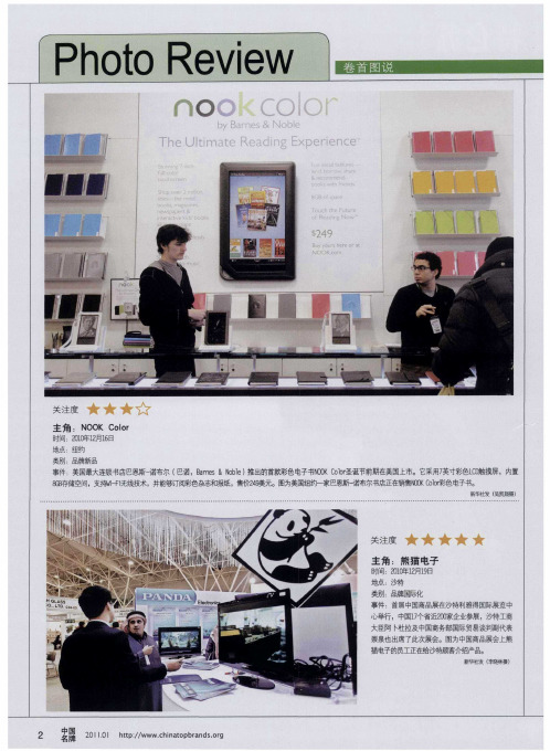
主 角 :N O oo O 6 ] 0
地点 : 纽约
类别:品牌嘶品 事件: 美国最大 连锁书 店巴 恩斯一 诺布尔 ( 诺, a e 巴 Bn r s&N l ) 的首款彩色电 o e 推出 b 子 ̄N KCl 圣诞节前期在 O o r O o 美国上 市。它采用7 英寸彩色L 触 c 摸屏,内 0 置 8B 6存储空间,支持 一{ F 无线技术, 并能够订阅彩色杂志和报纸, 售价 9 美元。图为美国纽约一家巴恩斯赫 尔书店正在销售NO l  ̄色m - OKC o or j 书。
品质系统三阶文件
系统名称: Quality Name:
品质管理系统 Quality management system
主题: Obje c t:
人员上岗 考核作 业办法
编号: NO.
QW-Q-041
版次: REV.: G
页数: Page:
2 /9
1 目的
为了激励基层员工踊跃学习生产技术、积极提升个人效率及技能,提升产品的品质,特制定
工培训/考核记录表中。 6.7 技术岗位员工之选拔,培训与考核:
6.7.1 人员选拔:线长必须选择合适的人选(如:新进人员不得从事技术岗位,从事该岗 位必须为入职一个星期以上或有同类工作经验人员。),先对其进行上岗前的理论 相关培训 2-4 小时。
6.7.2 技术工站人员还须在培训线进行实践操作,焊锡工站实践操作时间不得少于 4 小 时;成型、铆端、不良品维修实践操作时间不得少于 2 小时;其余工站实践操作 时间不得少于 1 小时。培训线进行实践操作的产品采取报废处理,不得用于正常 出货。
6.7.5 综合考核:现由 IPQC 对其进行实践考核,考试合格后方可进行理论考核。PQE 进行理论考试,且将考核结果填写于表单上,考核 OK 后给此员工发放技术人员 合格证,技术岗位员工必须考核 OK 后方可上岗作业。上岗作业前 4 小时须由品 质监控工站作业员重点统计及监控品质状况,若无对应品质监控工站则安排老员 工或线长进行全检 4 小时,确保实际操作效果。
系统名称: Quality Name:
品质管理系统 Quality management system
主题: Obje c t:
人员上岗 考核作 业办法
编号: NO.
QW-Q-041
版次: REV.: G
页数: Page:
saej2260v002
SURFACEVEHICLESTANDARD SAE Technical Standards Board Rules provide that: “This report is published by SAE to advance the state of technical and engineering sciences. The use of this report isentirely voluntary, and its applicability and suitability for any particular use, including any patent infringement arising therefrom, is the sole responsibility of the user.”SAE reviews each technical report at least every five years at which time it may be reaffirmed, revised, or cancelled. SAE invites your written comments and suggestions. Copyright © 2004 SAE InternationalAll rights reserved. No part of this publication may be reproduced, stored in a retrieval system or transmitted, in any form or by any means, electronic, mechanical, photocopying, recording, or otherwise, without the prior written permission of SAE.TO PLACE A DOCUMENT ORDER: Tel: 877-606-7323 (inside USA and Canada)Tel: 724-776-4970 (outside USA)2.2Related PublicationsThe following publications are for information purposes only and are not a required part of this document.2.2.1ASTM P UBLICATIONSAvailable from ASTM, 100 Barr Harbor Drive, West Conshohocken, PA 19428-2959.ASTM D 412—Test Methods for Rubber Properties in TensionASTM D 4000—Classification System for Specifying Plastic MaterialsASTM D 4066—Specification for Nylon Injection and Extrusion Materials3.Installation, Assembly, and Handling Recommendation3.1End FittingsEnd fittings can be assembled to the tubing providing that they do not cause mechanical damage to the tubing that results in decreased performance. Assemblies manufactured with tubing described in this document and end fittings must meet all of the requirements of SAE J2045.3.2Support and RoutingWhen installed in a vehicle this tubing shall be routed and supported so as to:a. Prevent chafing, abrasion, kinking, or other mechanical damage.b. Be protected against road hazards by installation in a protected location or by providing adequateshielding in vulnerable areas.c. Be protected from heat by proper clearance or the addition of insulation and/or heat shielding (refer toSAE J2027), for use in applications where temperatures exceed the upper limits of 115 °C.3.3HandlingTubing ends should be protected during handling and storage to prevent internal contamination.4.ConstructionTubing shall consist of an extrudate of one or more layers within the body of the wall. The dimensions and tolerances of the one or various layers shall be expressed in millimeters and the material name should be called out on the drawing.4.1MaterialsThe requirements of this document apply to the tubing as a whole and not necessarily to the individual materials used in the construction of the tubingF or monowall tubing, the material used must meet all applicable exposure criteria described in this document.4.2.2.3 A single construction of multilayer tubing in which one layer is regrind must be qualified. Oncequalified, the thickness and position of the regrind layer is fixed but any blend of regrind less than the amount qualified may be used in the regrind layer.4.2.2.4Qualification of a regrind/virgin resin blend applies only to the manufacturer who developed theregrind blend and tubing construction and obtained the qualification.4.2.3R EGRIND G UIDELINES4.2.3.1If single resin regrind is used to produce monowall tubing or the inner or outer wall of multilayerconstructions the amount of regrind in the blend shall be limited to 10% max.4.2.3.2Use of regrind might have an effect on the long term capability of tubing to resist exposure tolong term heat aging or zinc chloride. The end user should be consulted to determine if moreaggressive testing is necessary than listed in this document.4.3ColorThe outside layer of the tubing constructions is usually black although, alternative colors are permissible, if necessary, for purposes of color-coding. The following criteria must be met:a. The tubing color and the label color must be such that there is sufficient contrast to achieve easyreadability.b. Material used in outside layer of the MLT or as the material of the monowall tubing should be U.V.stabilized to withstand expected exposure (either with an additive or by the inherent characteristics of the material). Requirements necessary to adequately resist sunlight exposure will depend strongly on the application. The end user must be consulted for specific standards to be met. As a general guideline, also refer to SAE J1960.4.4Identification4.4.1The following minimum information, in the order listed, is required. Additional information and/oranother lay line may be added: SAE J2260 – L-D-Type-XX/YY-P.a. L refers to the construction of the tubing: (S for single layer and M for more than one layer)b. D refers to the reference size in mm from Tables A1 located in the Appendix.c. TYPE refers to the type of tube as indicated by two descriptions.1. The first description (xx) refers to conductivity and has 2 options:C: This is a tubing that is conductive as defined by Section 7.9N: This is a tubing that is non-conductive (the requirements of section 7.9 do not have to bemet)2. The second description is (YY) refers to pressure application and has 3 options:HPF: This is a type of tubing described in the scope as high-pressure liquid fuel line.LPF: This is a type of tubing described in the scope as low-pressure liquid fuel line.V: This is a type of tubing described in the scope as one that handles fuel vapor orevaporative emissions.These two descriptions are included by printing them with a “slash” line separating them. Two examples of this “type” as printed on the tubing would be:C/HPF and N/Vd. P refers to the permeation category as determined by the procedures described in 7.10. It shall be asingle digit that is identified from 7.10.5.If it is not practical to print on the outside of the tubing (convoluted tubing or tubing with an outside surface that is not smooth, for example), then the labeling will be done by a tag or loop of tape permanently attached to the outside circumference of the tubing. Such labeling must be repeated every 500 mm or less along the entire length.For convoluted or corrugated tubing, the necessary printing can be done by the labeling or tagging procedure that is described. An acceptable alternative is to print the necessary wording only on each straight end section.4.4.2E XAMPLES OF IDENTIFICATIONThe following are examples of appropriate identification of a tubinga. SAE J2260 – M-8-C/HPF-2: This is a multilayer tubing construction with an 8mm nominal O.D. It isconductive and is targeted toward a high pressure liquid fuel application; permeation category is 2. b. SAE J2260 – M-28-C/LPF-1: This is a multilayer tubing construction with a 28mm nominal O.D. It isconductive and is targeted toward a low-pressure liquid fuel application; permeation category is 1.c. SAE J2260 – S-14-N/V-4: This is a monowall tubing with a 14mm nominal O.D. It is non-conductiveand is targeted toward a fuel vapor application; permeation category is 4.5.Dimensions5.1Tubing Sizes and Dimensions5.1.1D IAMETERSTubing diameters refer to outside diameter (O.D.); standard sizes and their tolerances are listed in Tables A1 and A2 in the Appendix.5.1.2W ALL T HICKNESSThere are numerous factors that can have an influence on the wall thickness that is selected; for example:a. The burst pressure of a given tube construction and diameter is a function of its wall thickness.b. As walls become thicker, the minimum bend radius increases for a given tube diameter (for a free-form bend).c. For MLT constructions with elastomeric covers, the critical dimension is the ID. The wall thickness isdetermined by the materials utilized and the requirements of the applicationd. Tubing wall thickness may differ for convoluted/corrugated wall (refer to Section 6.3)The result of all these factors is that the end user must be consulted to determine all requirements. The wall thickness is then determined by those requirements and the materials selected for the various layers of the multilayer tubing or for the monowall tubing.Details on available standard wall thicknesses and their tolerances are found in Tables A1 and A2.5.3.2C ONNECTORS,P LUGS,M ANDRELSFor the various tests that are done, there are a variety of connectors, plugs, and mandrels that are used for the various exposure testing. The material from which those are made shall be a type 300 stainless steel or equivalent (as agreed to by end user and producer).6.Convoluted or Corrugated Tubing (CVT)6.1CriteriaSome applications may require tubing with flexibility beyond the capability of straight wall tubing. Tubing with a wall that has a convoluted or corrugated configuration for all or portions of its length can resolve this concern. A CVT may not have the same performance level as the equivalent straight-wall tube but still it must meet the pertinent acceptance criteria for all sections of this specification appropriate to it’s end use.6.2Test ConsiderationsThe convoluted or corrugated shape of the wall can effect how the CVT is handled as the tests are conducted. Some of these are identified in section 6.4; some others are mentioned in the sections that discuss a particular test. They can have an effect on how specific tests are conducted or results are reported.6.3Dimensional Considerations for CVT6.3.1The CVT shall be identified by its nominal ID; this is the same as ID of the straight wall section ateach end (known as the cuff of the CVT), see Table A1). In most cases, the inner diameter of the straight-wall portion is not exactly the same as the inner diameter of the corrugated area. Due to the manner in which most CVT is produced (with the so called “over-pressure-technique”), the diameter of the corrugated area has an inner diameter which is a little bit smaller than the inner diameter of the cuff ends. If the diameter of the cuff ends and the corrugated area are exactly the same, the sealing plug can touch the inner surface of the cuff ends and causes scratches and core “smear-marks” which then can cause leaks (when the connectors are inserted). Therefore, the inner diameter of the convoluted area typically ends up being about 0.1 mm smaller than the inner diameter of the cuff ends. When the tubes are produced with the “vacuum-technique” the inner diameter of the straight-wall can be exactly the same as in the corrugated portion of the tube.6.3.2At each end of the convoluted or corrugated tubing, there will be a straight section (known as thecuff) used to join the tubing to connectors, nipples, and other attachment elements. The dimensions of this cuff will correspond to those identified on Tables A1and A2 unless a non standard size has been specified.6.3.3Wall thickness of the convoluted/corrugated portions of the tubing may differ from those indicatedin Table A1 due to the manufacturing process. Performance tests results will be used to establish that such “routinely occurring” variations in wall thickness are acceptable.NOTE—For dimensional considerations of sections 6.3 refer to tables A2-1 and A2-3 in Appendix.6.4Test Considerations for CVT6.4.1When a test is performed on CVT type tubing, the required procedure can be conducted on eitherthe convoluted portion of the tube or on the straight sections (cuff, for example). These tests are identified in each test description where it is appropriate.6.4.2Wherever possible, tests should focus on the convoluted sections of the tubing. This can be anapplication of the procedure directly to the convoluted or corrugated wall (example is cold impact and kink test). F or layer adhesion, the procedure of 7.13.2 should be followed using the CVT section for all testing after fuel exposures. F or determination of initial layer adhesion, the cuff section should be used. (Section 7.13.1)6.5Consideration for Liquid Fuel Line ApplicationsAny CVT used in liquid fuel applications must meet the conductivity requirements called for in 7.9. In addition, the end user must have the final application carefully tested to determine that unacceptable electrostatic charging is avoided (refer to SAE J1645) during usage and when it’s being tested (such as during fuel recirculation or during permeation measurements (SAE J1737).7.Performance Requirementsa. All tests described in this standard are to be performed on the completed product (tubing) that hasnot been formed (all tests are done on straight tubing). Differences in performance criteria between high pressure liquid fuel, low pressure liquid fuel, and fuel vapor applications are indicated in the procedure or acceptance criteria of each section. If no distinction is made, all types of tubing must meet the entire requirement as written.b. The dimensions and configurations of test specimens used must conform to the guidelines ofsections 5.3 and 6.3, unless there are specific length or other criteria identified for a specific test.c. Tubing shall be allowed to equilibrate at 23 °C and 50% Relative Humidity for a minimum of 24 h afterproduction before it is subjected to any tests.d. For all testing in this section, there shall be a quantity of test specimens used as shown in Table 1.The result of testing each specimen must meet the acceptance criteria. When comparison are made from one section to another, the numeric value used in those comparisons shall be the average of the values obtained for the number of specimens of the specific test procedure.e. All test temperatures specified may vary by ± 2 °C, unless otherwise specified. All times are minimumunless otherwise specified.f. For testing that is done involving flowing fuel (fuel exposure-testing and permeation measurements),there is a possibility of electrostatic charge build up. This is more likely when the wall of the tubing is corrugated or convoluted and/or the material used in the innermost layer is not conductive. Steps should be taken to minimize the occurrence of electrostatic charges. These steps can include (but are not limited to) the following:• reduce flow of fuel to a very low rate• substitute weight loss procedures where such alternative test methods are acceptable• use conductive fittings for the testing and bond them to the appropriate ground plane It is recommended that pertinent sections of the Recommended Practice SAE J1645 be consulted.7.1Room Temperature Burst Test7.1.1I NITIAL B URST T EST M EASUREMENTThe tubing specimens shall be stabilized for ½ to 3 hrs at 23 °C and tested by increasing pressure of a suitable liquid fluid inside the tubing at a rate of 7 MPa/min ± 1 MPa/min. Continue at that rate until tubing bursts. Any type of fitting can be used during this burst test as long as it does not effect the burst capability of the tubing and meets the criteria of 5.3. If the connectors blow out of the tubing before the required level of burst pressure is reached, the data from that particular sample should be discarded. Additional clamps over the existing connectors or fittings may be utilized, if necessary, to ensure that the tubing sample fails by bursting.The initial value for room temperature burst for 5 test specimens must be recorded. The average of those test results will be used as the baseline for comparison of burst tests done on tubing that has been subjected to certain procedures and test fluid exposures (see 7.1.2).7.1.2B URST T EST M EASUREMENTS A FTER E XPOSURESThere are 5 sections of the performance requirements that include a subsequent burst test measurement (7.4, 7.5, 7.7, 7.8, and 7.14). After each of the steps described in each section, the tubing specimen subjected to the particular procedure/exposure is tested by the room temperature burst procedure described in section 7.1.1.NOTE—If the connectors blow out of the “exposed” tubing before the required level of pressure is reached, the result of that particular test should be discarded. The sample can be used again (another connector inserted) to avoid having to conduct the exposure test all over again.7.1.3A CCEPTANCE C RITERIA7.1.3.1For all test specimens that are exposed under the 5 identified sections, the measured burst testresult shall not be less than 75% of the measured initial burst test result on unexposed tubing(initial value obtained in section 7.1.1.).7.1.3.2It is possible for a tube to have a decrease greater than the level indicated in section 7.1.3.1and still be acceptable. For that to be the case, the following criteria must to met:a. After the initial drop off of greater than 25%, the performance of the tube can be proven to level offand to not drop below the minimum burst pressure of section 7.2.1.1 for the expected life of the application.b. Acceptance of such a construction shall be by a specific end user and for a specific producer.(Acceptance by one end user does not imply acceptance by any other end user and acceptance for one producer does not imply acceptance for any other producer).7.2High Temperature Burst Test7.2.1The test procedure described in 7.1.1 shall be performed at a temperature of 115 °C. The tubingshall be stablized at the test temperature for 2 hours prior to conducting the test. A minimum of 5 test specimens are to be used; test results of those 5 will be averaged.FIGURE 3—COLD IMPACT TEST FIXTURE7.5.1P REFERRED P ROCEDUREExpose the test samples and the impact test apparatus to –40 °C for 4 h. Place each sample in the supporting platform of the apparatus and allow the impact head to fall on it. Impact should occur with both apparatus and specimens inside the cold chamber.7.5.2O PTIONAL P ROCEDUREIf the impact test cannot be done inside the cold chamber, the apparatus and the specimens can be removed from the chamber by the following procedure:a. The apparatus is removed from the chamber for up to a 3 min period. During that period, impacttests of several tubing specimens can be completed. At the end of the 3 min period, the apparatus is returned to the chamber for additional temperature soak (–40 °C) of at least 25 min duration. After the additional soak at temperature, the apparatus can be removed again for an additional set of cold impact of tubing specimens (within a 3 min period). This procedure is repeated until all testspecimens have been impacted properly.b. All test specimens are kept in the cold chamber until immediately before impact in the apparatus.When a tubing specimen is removed, it must be impacted in the apparatus within 5 s of its removal from the cold temperature environment.NOTE—The temperature of the ambient air where these impacts occur shall not be higher than 23 °C.7.5.3A CCEPTANCE C RITERIASeveral types of specimens are tested by this impact procedure (after exposures of sections 7.6, 7.7, 7.8, 7.12 and 7.14). In each case, after impact of a tubing specimen, it is allowed to return to 23 °C. The tubing specimen is then subjected to Room Temperature Burst per (see 7.1). All criteria of that section must be met. The sample must be free of visible cracks and fractures (after impact and before burst test).7.6Fuel Exposure-PreconditioningThis is a long-term fuel exposure procedure designed to provide a pre-conditioning step to test specimens that are used in sections 7.5 (cold impact), 7.13 (layer adhesion) and the “C” test fluid exposure for section 7.9 (electrical resistance).This procedure is not intended as a routinely required test because it takes too much time. It is for the initial qualification for each particular wall configuration of a given type of tubing.7.6.1The two test fluids for this procedure shall be “C” and “CE-10”, as described in SAE J1681.7.6.1.1For test fluid C, its composition should remain constant during the full time of exposure. Theimportant consideration is to maintain appropriate fluid levels.7.6.1.2F or test fluid CE-10, the composition of the fluid can change with time (especially alcoholcontent). Besides maintaining the appropriate fluid levels, the alcohol content must be maintained as described in sections 7.6.4.1 (recirculation method) and sections 7.6.4.2 (reservoir/tubing method).7.6.2The temperature of test fluid used in the exposure shall be 60 °C.7.6.3T EST S PECIMENS7.6.3.1For the recirculation method of 7.6.4.1, the tubing can be exposed to the test fluids before it iscut to length (as specified in 5.3.1) for the subsequent tests.7.6.3.2F or the reservoir method of 7.6.4.2, the length of test specimens being exposed to the testfluids shall be as specified in 5.3.1.7.6.3.3F or each specific, defined configuration of layers in the wall construction, only one diametershould be tested for a given wall thickness. Separate tests must be done on tubes having thesame ID, but wall thicknesses or layer configurations that are different.7.6.4P ROCEDURESThere are two procedures described here for exposing the test specimens to each of the two test fluids: Recirculation method (7.6.4.1) and Reservoir/tubing method (7.6.4.2) The procedure of section 7.6.4.1 shall be followed for tubing intended for high pressure liquid fuel applications. For tubing intended for low pressure liquid fuel applications and fuel vapor applications, the procedure of 7.6.4.1 is recommended; however, the optional procedure of section 7.6.4.2 may be followed.7.6.4.1Recirculation Method7.6.4.1.1For test fluid C, follow the recirculation procedure of SAE J1737.7.6.4.1.2For test fluid CE-10, the same procedure of SAE J1737 is followed; however steps must betaken to maintain the alcohol content as described in the following paragraph.Composition of the fuel should be measured and adjusted periodically to ensure that thealcohol content of the fuel is maintained at 10% ± 2% (frequency of the checking of thecomposition is determined primarily by the size of the liquid fuel reservoir used in therecirculation process). Alcohol content shall be measured every day after the start of testuntil it is established that the rate of alcohol content change is less than + 2% over a longerperiod of time. The frequency of checking alcohol content can then be decreased. If thesetests are done frequently and a history of how often the alcohol should be checked can besubstantiated from previous test specimens, then that established schedule can be utilized.Alcohol content shall always be checked at least once per week. If the alcohol content of thefuel goes outside of the limits, the test fuel must be replaced with a new mixture with thecorrect level or alcohol.7.6.4.2Reservoir/Tubing Method7.6.4.2.1For test fluid “C”, follow the procedure as described in SAE J2663.7.6.4.2.2For test fluid CE-10, follow the procedure as described in SAE J2663. Steps must be takento maintain the alcohol content of the test fluid (7.6.4.1.2 procedure can be followed).7.6.5P ROCEDURES7.6.5.1For “C” Test Fluid7.6.5.1.1Using recirculation method continuously expose a length of tubing (1.0 meters or more) toASTM fuel C for 1000 hrs @ 60 °C. At the end of the exposure, five (5) specimens are cut tolength (200mm minimum) and used in the procedure of section 7.9.7.6.5.1.2Using reservoir method, continuously expose a minimum of 5 test specimens to ASTM fuel Cfor 1000 hrs @ 60 °C. At the end of that period, the other 5 specimens (200 mm minimumlength) are used in the procedures of section 7.9 (electrostatic charge procedures).7.8Resistance to Auto-Oxidized Fuel7.8.1The fuel exposure and preconditioning steps of section 7.6 shall be followed for the followingconditions:Test temperature 40 °CTest exposure time 1000 hrs.Test fluid Auto oxidized test fluid uses a base fuel of ASTM Fuel C and has a concentration of 50 millimols/1 of tertiary-butyl-hydroperoxide (TBHP) (using copper additive)as described in SAE J1681. The concentration must be maintained ±millimols/liter throughout the entire exposure. A technique similar to themaintenance of alcohol percentage in 7.6.4.1.2 or 7.6.4.2.2 (whichever ispertinent) should be followed.Test specimens Quantity needed depends number of layer interfaces that are in the MLT being tested (refer to section 5.3 as well as 7.6.3 for details). The specimens can beexposed individually or in a full- length, then cut-to-size as needed.Subsequent procedures on tubing that have been exposed to auto-oxidized test fluid for the full 1000 hrs @ 40 °C.•Five (5) test specimens are needed to test for cold impact resistance per 7.5 (including the burst test).The cold soak must be started immediately after emptying the tubing of the sour gas fuel (to avoid any drying out of the tubing).•Test for layer adhesion per section 7.13.2 (need 5 test specimens for each layer interface).7.8.2A CCEPTANCE C RITERIAAll criteria of sections 7.5 and 7.13 shall be met for all tubing tested.7.9Conductive TubingLiquid carrying fuel tubes (both high pressure and low pressure) designated as conductive per section 4.4 of this document shall have a conductive inner layer and meet the conductivity requirements of this test method. For monowall tubing, the whole tubing all meet those conductivity requirements.For tubing used in fuel vapor and evaporative emissions systems, electrostatic charge is not an issue, so section 7.9 is not required for those applications. (Refer to SAE J1645 for details about this).7.9.1R EFERENCE D OCUMENT FROM SAESAE J1645 is a Recommended Practice that addresses the issue of electrostatic charge that may develop in a flowing liquid fuel system. It gives guidelines that should be followed on liquid tube and how it should be integrated into a fuel system to minimize the adverse effects that can develop from an electrostatic charging condition. These guidelines include such matters as configuration of the tube, assembly issues, and bonding to the vehicle ground. When developing a system to carry liquid fuel, care must be taken to consider all aspects of the system from an electrostatic charge perspective7.9.4T ESTING A FTER E XPOSURES7.9.4.1There are 3 sections in this specification where tubing samples have been subjected to othertests or preconditioning and then are to be tested to determine if they maintain their performance levels adequately.Section 7.4—Kink Procedure: After two kinking steps are done, the surface resistivity is determined. (No subsequent burst test is done in this particular case)Section 7.5—Cold Temperature Impact: After the tubing specimen has been impacted per section 7.5, it is allowed to return to 23 °C. (No subsequent burst test is done in thisparticular case)Section 7.6—F uel Exposure: After exposure to ASTM fuel C for 1000 hrs @ 60 °C as described in section 7.6.5, the surface resistivity of the 5 exposed test specimens isdetermined. NOTE: The test fluid used in this fuel exposure part of the testing does notcontain any alcohol for reasons described in SAE J1645 (sections 5.3 and Appendix A1.7).7.9.4.2Test ProcedureFor testing after exposures, the procedure of section 7.9.3. is used. For the fuel exposed specimens of section 7.6.5, the measurements shall be taken within 2 hours after the exposure fuel has been removed from the exposed test specimens. Acceptance criteria of section 7.9.5 applies to both procedures.7.9.5A CCEPTANCE C RITERIASurface Resistivity Level—The surface resistivity determined from measured resistance values measured on test specimens both before and after exposure testing shall not be greater than 106Ω/square.7.10Permeation Test Procedure7.10.1T EST C ONDITIONSThe test fluid shall be CE-10 as described in SAE J1681. For that test fluid, the temperature the test shall be 60 °C and the pressure of the circulating test fluid shall be 2 bar.7.10.2T EST S PECIMENSThe tubing used in this procedure shall conform to the requirements of SAE J1737 and the criteria of section 5.3 of this document.7.10.3P ROCEDUREThe permeation measurement shall be done using the recirculation method of SAE J1737 and refer to section 7.6.4.4.2 for the reservoir tube method). The test shall be until steady state is achieved (as described in SAE J1737).7.10.4R EPORTING R ESULTSThe steady state permeation measurement results shall be recorded; all measurements are to be recorded in grams/meter2·day of tubing.。