操作手册PDM820-800BT
Moxa UC-8200 Series计算平台说明书

P/N: 1802082000011 *1802082000011*UC-8200 Series Quick Installation GuideVersion 2.0, March 2020Technical Support Contact Information/supportMoxa Americas:Toll-free: 1-888-669-2872 Tel: 1-714-528-6777 Fax: 1-714-528-6778 Moxa China (Shanghai office): Toll-free: 800-820-5036 Tel: +86-21-5258-9955 Fax: +86-21-5258-5505 Moxa Europe:Tel: +49-89-3 70 03 99-0 Fax: +49-89-3 70 03 99-99 Moxa Asia-Pacific:Tel: +886-2-8919-1230 Fax: +886-2-8919-1231 Moxa India:Tel: +91-80-4172-9088 Fax: +91-80-4132-10452020 Moxa Inc. All rights reserved.OverviewThe UC-8200 Series computing platform is designed for embedded data acquisition applications. The UC-8200 Series computer comes with two RS-232/422/485 serial ports and dual 10/100/1000 Mbps Ethernet LAN ports, as well as two Mini PCIe sockets to support cellular and Wi-Fi modules. These versatile communication capabilities let users efficiently adapt the UC-8200 Series to a variety of complex communications solutions.Package ChecklistBefore installing the UC-8200 Series, verify that the package contains the following items:•UC-8200 Series embedded computer•Power jack•Console cable•DIN-rail mounting kit•Quick installation guide (printed)•Warranty cardUC-8200 Series Panel LayoutThe following figures show the panel layouts of the UC-8200 Series: UC-8210Top Panel ViewFront Panel ViewUC-8220Top Panel ViewFront Panel ViewLED IndicatorLED Name Status FunctionPWR1/PWR2 Green Power is onOff No powerSIM Green SIM2 in useYellow SIM1 in useUSR Green/Yellow User programmableL1/L2/L3 Yellow Cellular signal strengthL1+L2+L3: StrongL2+L3: NormalL3:WeakW1/W2/W3 Yellow WLAN signal strengthL1+L2+L3: strongL2+L3: normalL3: weakLED Name Status FunctionLAN1/LAN 2 (RJ45 connector)Green Steady on 1000 Mbps Ethernet link BlinkingData is being transmittedYellowSteady on 100 Mbps Ethernet link Blinking Data is being transmitted OffNo Ethernet connectionInstalling the UC-8200 SeriesDIN-rail MountingThe aluminum DIN-rail attachment plate is already attached to the product’s casing. To mount the UC-8200 Series on to a DIN rail, make sure that the stiff metal spring is facing upwards and follow these steps.1. Pull down the bottom slider of the DIN-rail bracket located at the back of the unit2. Insert the top of the DINrail into the slot just below the upper hook of the DIN-rail bracket.3. Latch the unit firmly on tothe DIN rail as shown in the illustrations below.4. Push the slider back intoplace.UC-8210 UC-8220Wall Mounting (optional)The UC-8200 Series can be mounted on to a wall using a wall-mounting kit. The optional wall-mounting kit should be purchased separately. Follow these steps to mount the computer on to a wall:Step 1Use four screws to fasten the wall-mounting brackets on the left panel of the computer. Step 2Use another four screws to mount the computer on to a wall or in a cabinet.NOTE •Test the screw head and shank size by inserting the screws into one of the keyhole shaped apertures of the wall-mounting plates before attaching the plate to the wall. •Do not drive the screws in all the way—leave a space of about 2 mm to allow room for sliding the wall mount panel between the wall and the screws.Connector DescriptionPower ConnectorConnect the power jack (in the package) to the UC-8200 Series’ DC terminal block (located on the top panel), andthen connect the power adapter. It takes about 30 seconds for the system to boot up. Once the system is ready, the Power LED will light up. Both models support dual power inputs for redundancy.Use wires with 16 to 24 AWG (1.318 to 0.205 mm 2) to connect to V+,V-, and GND. The wire size of the power input and the earthing conductor should be the same.Grounding the ComputerThere is a grounding connector located on the top panel of thecomputer. Grounding and wire routing help limit the effects of noise due to electromagnetic interference (EMI). Connect to an appropriate grounded metal surface. Ethernet PortsThe two 10/100/1000 Mbps Ethernet ports (LAN 1 and LAN 2) use RJ45 connectors.Pin 10/100 Mbps1000 Mbps 1 Tx+ TRD(0)+ 2 Tx- TRD(0)- 3 Rx+ TRD(1)+ 4 – TRD(2)+ 5 – TRD(2)- 6 Rx- TRD(1)- 7 – TRD(3)+ 8–TRD(3)-Serial PortsThe two serial ports (P1 and P2) use DB9 interface. Each port can be configured by software for RS-232, RS-422, or RS-485. The pin assignments for the ports are shown in the following table:PinRS-232RS-422/ RS-485 4w RS-485 2w1 – TxD-(A) –2 RxD TxD+(B) –3 TxD RxD+(B) Data+(B)4 DTR RxD-(A) Data-(A) 5GND GND GND 6 DSR – – 7 RTS – – 8CTS––microSD Card SocketsThe UC-8200 Series comes with a micro SD socket for storageexpansion. The microSD socket is located at the lower part on the front panel. To install the card, remove the screw and the protection cover to access the socket, and then insert the microSD card into the socket directly. You will hear a click when the card is in place. To remove the card, push the card in before releasing it.Console PortThe console port is an RS-232 port located on the top panel, and can be connected to a 4-pin pin header cable. You can use this port for debugging or firmware upgrade.Pin Signal 1 TxD 2 RxD 3 NC 4GNDUSB PortThe USB 2.0 port is located at the lower part of the front panel and supports a USB storage device driver. By default, the USB storage is mounted at /mnt/usbstorage. CAN PortA CAN port with a DB9 interface is located on the bottom panel. Refer to the figure below for detailed pin definitions.PinDefinition1 –2 CAN_L3 CAN_GND4 –5 (CAN_SHLD)6 (GND)7 CAN_H8 – 9(CAN_V+)Digital Inputs/OutputsThere are four digital inputs and four digital outputs on the top panel. Refer to the figure on the left for detailed pin definitions.SIM Card SocketThe UC-8220 computer comes with a SIM card socket that allows users to install two SIM card for the cellular communication. Step 1Remove the screw on the SIM card holder cover located on the bottom panel of the UC-8220 computer.Step 2Insert the SIM card into the socket. Make sure you insert in the right direction. To remove the SIM card, press the SIM card in to release and then you can pull out the SIM card.Real-time ClockThe real-time clock in the UC-8200 Series is powered by a lithium battery. We strongly recommend that you do not replace the lithium battery without the help of a Moxa support engineer. If you need to change the battery, contact the Moxa RMA service team.Accessing the UC-8200 Series Using a PCYou can use a PC to access the UC-8200 Series by one of the following methods:A. Through the serial console port with the following settings:Baudrate =115200 bps, Parity =None, Data bits =8, Stop bits =1, Flow Control =NoneRefer to the following IP addresses and login information:Default IP Address NetmaskLAN 1 192.168.3.127 255.255.255.0 LAN 2192.168.4.127 255.255.255.0Login: moxaPassword:moxaInstalling the Cellular ModuleThe UC-8220 Series comes with two PCIe sockets, allowing users to install a cellular and a Wi-Fi module. Some models have been shipped with a built-in cellular module inside the computer. However, if you purchase the UC-8200 series without a cellular module, follow these steps to install the cellular module.1. Remove the four screwson the side panel of the computer.2. Remove two screws on theother side panel to open the side cover of the computer.3.The socket is located on the main board of the computer.4.Install the cellular module onto the socket and fasten the twoscrews on the module.5.Connect the antenna cables to the antenna connectors.6.The UC-8220 Series supports two cellular antennas and a GPSantenna. Connect the cable to the correct antenna connectors. 7.When finished, place the side cover back on the computer andsecure it.Installing the Wi-Fi ModuleThe Wi-Fi module is not included in the package, you need to purchase separately. The Wi-Fi module package includes the following items:Follow these steps to install the Wi-Fi module.1.Remove the side cover of the computer to expose the Wi-Fimodule socket.The Wi-Fi socket is located beside the cellular module socket.2.Remove the two silverscrews on the socket. 3.Install the Wi-Fi modulein the socket and fastentwo black screws on themodule. Also, fasten thetwo bronze screws onthe board.4.Remove the plastic protection covers on the antenna connectors.5.Connect the antenna cables to the antenna connectors.The Wi-Fi module supports two antenna connectors, connect the cables to the correct antenna connectors.6.Install the heat sink pad on the module and then fasten two silverscrews.7.Replace the side cover.Connecting AntennasThere are two cellular antenna connectors (C1 and C2) on the front panel of the UC-8220 Series. In addition, a GPS connector is provided for the GPS module. All three connectors are of SMA type. Connect the antennas to these connectors as shown below. There are two Wi-Fi antenna connectors (W1 and W2) on the top panel of the UC-8220 Series. Connect the antennas on the connectors as shown below. Both W1 and W2 connectors are of RP-SMA type.ATEX, IECEx, and C1D2 SpecificationsModel UC-8210-T-LX, UC-8210-T-LX-S, UC-8220-T-LX Rating Input: 12 to 48 VDC; 1.0 to 0.25 AATEX InformationII 3 GCertificate Number: DEMKO 19 ATEX 2302XCertification String: Ex nA IIC T4 GcAmbient Range: -40°C ≦Tamb ≦70°C (withLTE module for model UC-8220-T-LX)Rated Cable Temp ≧100°CIECEx Certificate No. IECEx UL 19.0111XC1D2 Information Temperature Code (T-code): T4Manufacturer’s Address Flr. 4, No.135, Lane 235, Baoqiao Rd. Xindian Dist., New Taipei City, TaiwanHazardous Location Certification EN 60079-0:2012+A11:2013/IEC 60079-0 Ed.6 EN 60079-15:2010/IEC 60079-15 Ed.4。
BT Manual for NXT

BarTector 操作手冊Layout注意事項★ 請維持網路連線。
★ 請勿關閉BarTector Server 及 Flexa Server。
★ 請勿更改Flexa中Line、Machine、Group設定。
若有無法抗拒之因素,請通知Bartector 原廠人員。
★ 務必要求作業員上料、接料、下料均落實輸入資料(掃描條碼)。
開機程序1. 確認BarTector Server及Flexa Server開機。
2. 開啟線上BarTector PC。
3. 確認Open Interface啟動。
開始(Start)Æ設定(Settings)Æ控制台(Control Panel)Æ系統管理工具(Administrative tools)Æ服務(Service),確認Fuji Central Server已啟動。
4. 點選桌面上捷徑5. 輸入User Name及Password →按下OK6. 開啟NXT主電源。
(若NXT開啟時,Bartector電腦尚未開機,設備將無法連線,也無法生產。
)7. NXT電源開啟後,會自動Download置件程式,此時Bartector也同時自動下載料表資料,請確認程式名稱與NXT相同。
8. 若設備上有正確料號之Feeder,LED將自動變綠,完成開機。
BarTector視窗說明1. Title Bar公司名稱 :: 機器名稱 :: 程式名稱母視窗顯示之機器名稱為接收指令的機器。
同時監控兩台以上機器時,可點選子視窗切換。
2. 工具列3. 即時生產情報排序方式依據剩餘PCB數量,剩5片變黃色,剩3片變紅色。
(可更改)4. 訊息視窗顯示各項訊息,包含上料、接料、下料、換程式等。
Fuji Flexa程式編輯注意事項 (For BarTector)1. 字元限制★ Job name 不可超過50字元。
★ Revision 不可含有底線”_”,不可超過20字元。
BT200使用手册

BT200使用手册——用于PROFIBUS-DP的总线测试诊断工具1 概述BT200的使用功能它可以提供用于PROFIBUS-DP系统的诊断而不需要再使用额外的测量器件(如,PC 或示波器)BT200-版本2BT200的第二个版本可以提供如下的附加功能:●登录操作●6种可选用户语言●DP主站接口测试●主站地址显示●从站接口测试●新型廉价紧凑型充电装置操作控制面板及显示1)DP接口2)LC显示3) 开/关键4)线充电接口5)测试键(开始测试)6)方向键7) Ok键(各种功能)8)取消键(终止)9)座充电接口2 设定在初始化设定之前,要检查并更换电池。
打开电池端盖,检查电池是否已经装好,如果需要的话安装好电池。
在更换电池期间,不能进行测试。
3 常规模式BT200由开关键打开。
保持其按下直到在屏幕上出现反应为止。
标准显示在开机后将显示下面图画然后显示电池情况电池状况显示过后,BT200默认进入常规模式并显示用于写测试的开机屏幕在常规模式下只能进行写测试。
当在登录模式下(指针看起来是不一样的),在每次测试之后会再出现如下画面电能节省模式如果3分钟内没有进行任何操作,那么BT200将会自动关闭3.1 写测试测量原则总线段的写测试在BT200与测试连接器之间进行。
在安装阶段,可以在连接器之间进行一个测试,如下图所示,测试连接器通常安装在总线段的另一端。
在测试路径之外也会造成短路。
总线段必须要在两端设置终端电阻。
进行测试可以在连接站点或断开的情况下进行测试。
在按下测试键之后,测试就开始了。
如果测试成功的话,将会显示下述两幅画面之一。
只有一个终端电阻(只要安装没有完成,只会显示一个终端电阻)当安装完成之后,会出现两个终端电阻。
按下OK键,测试即结束。
接下来也可以进行新的测试。
测试也可以在按下ESC键之后被终止。
3.2 写测试的错误信息站测试检测是否将所有站点以及电能部件的能量已经断掉。
线混合在相应的连接插头之间交换电缆线芯短路定位并纠正短路故障。
GDS-820 840 数字存储示波器使用手册
目录页数1.安全术语和符号 (2)2.产品介绍 (3)3.首次操作 (5)4.面板介绍 (8)5.操作说明 (14)6 方框图 (49)7. RS-232配置 (50)8.产品规格 (53)9.使用标准 (60)121.安全术语与符号以下各种安全符号可能会出现在这本操作手册或本产品上:警告﹕表示产品在某一确认情况下或是在实际应用上之结果可能会对人体产生伤害甚至于造成生命之损失。
注意﹕表示产品在某一确认情况下或是在实际应用上之结果可能会对本产品或是其它产品造成损坏。
以下各种安全符号可能会出现在这本操作手册或本产品上:危险高电压 注意 内容参考本手册 保护性导电端子 接地端 接地端2.产品介绍GDS-820/840是一种好用的,双通道数字存储示波器,特征如下:l频宽150MHz(GDS-840系列为250MHz),每一通道取样率100Msa/s (每通道25GSa/s E.T取样率)。
l可侦测到10ns的短时脉冲。
l 5.7”单色或彩色LCD显示(GDS-820,GDS-820S和GDS-840S为单色显示,GDS-820C和GDS-840C为彩色显示)。
l两个输入通道,每一通道的记录长度为125k点和8个字节的垂直分辨率,每个通道可同时采集波形。
l时基:1ns/div~10s/div。
l6位触发计频器。
l自动快速调整和手动操作。
l四种采集模式:取样,峰值侦测,平均,累加。
l游标和15种连续可调,自动量测:Vhi,Vio,Vmax,Vmin,Vpp,Vaverage,Vrms,Vamp,上升时间,下降时间,工作周期,频率,周期,。
l15组储存器用于前面板设置存取。
l2组存储器可用于波形轨迹记录。
l FFT频谱分析。
l具有“program mode”和“Go-No Go”功能。
l视频和脉冲宽度触发。
l8×12格波形显示(关闭菜单)。
l具有打印机接口,RS-232和USB输出接口,GPIB界面模块(所有的界面模块只有GDS-820S,GDS-820C,GDS-840S,GDS-840C 可用)。
AC800M选项手册
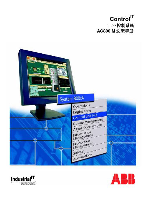
ControlIT工业控制系统 AC800 M 选型手册Control ITAC800M 控制器与 I/OAC 800M 控制器AC800M控制器是导轨安装式模块化 控制器家族,其中包括CPU、通讯模 块、电源模块和各种附件。
可供选择 的CPU根据其处理能力、内存大小及 是否支持冗余分成几类。
每个 CPU 模块配备有两个以太网端口,用于连 接操作员站、工程师站、管理站及更 高层次的应用。
这两个以太网端口可 配置成冗余,用于提高系统的可利用 性。
另外还配备了两个RS-232C端口, 可供 CPU 与编程 / 调试工具以及第 三方系统和设备之间进行通讯。
基于在现场各层次的冗余选择,AC 800M 系统确保满足您生产上的全部功能需求该模块上可以添加若干通讯和I/O 模块,例如: 另加的RS-232C 端口,可以使系统连接更多的第三方系统和设备。
Profibus DP、DP/V1 接口,使S200、S800及S900 I/O系统以远程I/O的集成,同时可 支持市场上的符合 Profibus 通讯协议的产品和设备, Foundation Field bus 接口,提供基金会现场总线的HSE,可直接连接FF总线H1适配 器 ABB INSUM 接口, 直接支持对电气开关柜控制和监视。
MasterBus 300 接口,支持Advant OCS 和ABB Master 系统。
S100I/O 接口,支持从现有的 Advant 410/450 及 MasterPiece 200系统升级到AC 800M 系统。
I/O模块,S800 I/O作为AC800M本地I/O模块。
以上这些连接方式和扩展选择使 AC800M 无比的开放和可扩展。
非常容易与现有应用的各种系 统、设备、接口相连接,用户可以根据不同需求,选择基本系统,或今后扩展以适应各种变化 需求。
1Control ITAC800M 控制器与 I/OAC800M 控制系统2Control ITAC800M 控制器与 I/OCPU 概述PM8518MB 24 MHz 用于中等性能范围,经济型项目 适用于中等性能范围的小型和中型系统 (Modulebus最大支持24块I/O模块(12个传动单元), CEX总线只能扩展一个通讯模块;只有一个标准以 太网口有效)PM8568MB 24 MHz适用于中等性能范围的需要更高要求的场合 适用于中、大型系统 Modulebus最大支持96块I/O模块(84个传动单元), CEX总线扩展12个通讯模块PM8608MB 48 MHzPM86116MB 48 MHz适用于高性能级别范围 适用于大型系统 Modulebus最大支持96块I/O模块(84个传动单元), CEX总线扩展12个通讯模块PM86432MB 96 MHzPM86532MB 96 MHz适用于高性能级别范围,控制器中整合安全和对系 统有重要意义的过程控制 适用于从小到大、所有那些对安全和业务具有重要 意义的过程自动化系统。
DMG80480C070_15WTR 数据手册说明书

DMG80480C070_15WTR产品特点:●基于T5L0芯片,运行DGUS II系统,商业级。
●7.0寸,800*480分辨率,262K色,TV-TN屏。
●电阻触摸屏。
●带外壳。
Features:●Based on T5L0,running DGUS II system,commercial grade.●7.0-inch,800*480pixels resolution,262K colors,TV-TN-TFT-LCD.●Resistive touch screen.●With shell.1、硬件及接口Hardware and interface1.1硬件接口图Hardware interface硬件接口图Hardware interface1.2接口说明Interface description序号No.名称Name说明Description1T5L0芯片T5L0ASIC迪文自主研发,2020年量产,1MBytes片内Nor Flash,其中512KBytes用于存储用户数据库,擦写次数>100,000次Developed by DWIN.Mass production in2020,1MBytes Nor Flash on thechip,512KBytes used to store the user database.Rewrite cycle:over100,000times2液晶屏接口LCM interfaceFPC50_0.5mm,RGB接口FPC50_0.5mm,RGB interface3电阻触摸屏接口RTP interface4Pin_1.0mm接口4Pin_1.0mm interface4用户接口User interface用于供电和串口通讯,8Pin_3.81mm座子。
串口下载速率(典型值):12KByte/s8Pin_3.81mm socket for power supply and serial communication.Download rate(typical value):12KByte/s5Flash 8MBytes NOR Flash,存放字库、图片、音乐文件,擦写次数>100,000次8MBytes NOR Flash,for fonts,pictures and audio files.Rewrite cycle:over100,000times6扩展Flash接口Expand Flash可以扩展到56Mbytes NOR Flash或40Mbytes NOR Flash+512MbytesNAND FlashExpandable to56Mbytes NOR Flash or40Mbytes NOR Flash+512MbytesNAND Flash7蜂鸣器Buzzer3V无源蜂鸣器,功率:<1W3V passive buzzer.Power:<1W8RTC 纽扣电池供电,精度:±20ppm@25℃Button cell for power supply.Accuracy:±20ppm@25℃9SD卡接口SD interfaceFAT32格式,下载文件,文件可在屏幕统计显示,下载速率:4Mb/sFAT32.Download files by SD interface can be displayed in statistics.Download rate:4Mb/s10PGT05接口PGT05interface当产品因意外无法正常运行时,可通过PGT05更新DGUS底层,使产品重新恢复正常When product crashes by accident,you can use PGT05to update DGUSkernel and make the product return to normal2、规格参数Specification parameters 2.1显示参数Display parameters显示屏类型LCD TypeTV-TN,TFT LCD视角Viewing Angle TV视角,典型值70°/70°/40°/30°(L/R/U/D)TV viewing angle,70°/70°/40°/30°(L/R/U/D)分辨率Resolution 800×480(支持0°/90°/180°/270°显示模式)800×480pixels(support0°/90°/180°/270°)色彩Color 18位6R6G6B 18-bit6R6G6BAA区Active Area(A.A.)154.1mm(W)×85.9mm(H) VA区View Area(V.A.)-背光模式Backlight ModeLED背光寿命Backlight Service Life >10000小时(以最高亮度连续工作,亮度减半时间)>10000hours(Time of the brightness decaying to50%on the condition of continuous working with the maximum brightness)背光亮度Brightness200nit背光调节Brightness Control 100级亮度调节(当亮度调节至最高亮度的1%~30%时,可能出现闪烁现象,不建议在此范围使用)0~100grade(When the brightness is adjusted to1%~30%of the maximum brightness,flickering may occur and is not recommended to use in this range)注:超过30分钟长时间显示高对比度静止画面可能导致显示残影,请增加屏保避免该问题。
罗克韦尔自动化 Trusted T8200 高可靠电源系统 使用手册说明书
PD_T8200 Trusted Trusted High Integrity Power Supply System (110-240 Vac and 24 Vdc)Product OverviewThe Trusted® power supply assembly converts redundant main line voltages of either 110 Vac / 240 Vac or 24 Vdc, to +15 Vdc or +24 Vdc output power for system and field power requirements.Features:•Redundant power inputs.•250 W.•Hot replaceable.•Current sharing.•Power factor correction.•Front panel indicators for input, output voltage status and output current level on each module.•External status signals.•TϋV Certified IEC 61508 SIL 3.Trusted PD_T8200Page intentionally left blankPREFACEIn no event will Rockwell Automation be responsible or liable for indirect or consequential damages resulting from the use or application of this equipment. The examples given in this manual are included solely for illustrative purposes. Because of the many variables and requirements related to any particular installation, Rockwell Automation does not assume responsibility or reliability for actual use based on the examples and diagrams.No patent liability is assumed by Rockwell Automation, with respect to use of information, circuits, equipment, or software described in this manual.All trademarks are acknowledged.DISCLAIMERIt is not intended that the information in this publication covers every possible detail about the construction, operation, or maintenance of a control system installation. You should also refer to your own local (or supplied) system safety manual, installation and operator/maintenance manuals. REVISION AND UPDATING POLICYThis document is based on information available at the time of its publication. The document contents are subject to change from time to time. The latest versions of the manuals are available at the Rockwell Automation Literature Library under "Product Information" information "Critical Process Control & Safety Systems".TRUSTED RELEASEThis technical manual applies to Trusted Release: 3.6.1.LATEST PRODUCT INFORMATIONFor the latest information about this product review the Product Notifications and Technical Notes issued by technical support. Product Notifications and product support are available at the Rockwell Automation Support Centre atAt the Search Knowledgebase tab select the option "By Product" then scroll down and select the Trusted product.Some of the Answer ID’s in the Knowledge Base require a TechConnect Support Contract. For more information about TechConnect Support Contract Access Level and Features please click on the following link:https:///app/answers/detail/a_id/50871This will get you to the login page where you must enter your login details.IMPORTANT A login is required to access the link. If you do not have an account then you can create one using the "Sign Up" link at the top right of the web page.DOCUMENTATION FEEDBACKYour comments help us to write better user documentation. If you discover an error, or have a suggestion on how to make this publication better, send your comment to our technical support group at SCOPEThis manual specifies the maintenance requirements and describes the procedures to assist troubleshooting and maintenance of a Trusted system. WHO SHOULD USE THIS MANUALThis manual is for plant maintenance personnel who are experienced in the operation and maintenance of electronic equipment and are trained to work with safety systems. SYMBOLSIn this manual we will use these notices to tell you about safety considerations.SHOCK HAZARD: Identifies an electrical shock hazard. If a warning label is fitted, it can be on or inside the equipment.WARNING: Identifies information about practices or circumstances that can cause an explosion in a hazardous environment, which can cause injury or death, property damage or economic loss.ATTENTION: Identifies information about practices or circumstances that can cause injury or death.CAUTION: Identifies information about practices or circumstances that can cause property damage or economic loss.BURN HAZARD: Identifies where a surface can reach dangerous temperatures. If a warning label is fitted, it can be on or inside the equipment.This symbol identifies items which must be thought about and put in place when designing and assembling a Trusted controller for use in a Safety Instrumented Function (SIF). It appears extensively in the Trusted Safety Manual.IMPORTANT Identifies information that is critical for successful application and understanding of the product.NOTE Provides key information about the product or service.TIP Tips give helpful information about using or setting up the equipment.WARNINGS AND CAUTIONSWARNING: EXPLOSION RISKDo not connect or disconnect equipment while the circuit is live or unless the area is known to be free of ignitable concentrations or equivalentAVERTISSEMENT - RISQUE D’EXPLOSIONNe pas connecter ou déconnecter l’équipement alors qu’il est sous tension, sauf si l’environnement est exempt de concentrations inflammables ou équivalenteMAINTENANCEMaintenance must be carried out only by qualified personnel. Failure to follow these instructions may result in personal injury.CAUTION: RADIO FREQUENCY INTERFERENCEMost electronic equipment is influenced by Radio Frequency Interference. Caution should be exercised with regard to the use of portable communications equipment around such equipment. Signs should be posted in the vicinity of the equipment cautioning against the use of portable communications equipment.CAUTION:The module PCBs contains static sensitive components. Static handling precautions must be observed. DO NOT touch exposed connector pins or attempt to dismantle a module.ISSUE RECORDIssue Date Comments8 Sep 05 Format9 Mar 06 Removed hidden characters10 Sep 15 Rebranded and reformatted11 Apr 16 Standardisation of Operating Temperature and Relative Humidity RangeStatements in the Specification sectionPage intentionally left blankTrusted High Integrity Power Supply System Table of Contents Table of Contents1.Description (3)1.1. Power Supply Chassis (3)1.2. Power Supply Modules (4)1.3. Input Power Regulation (4)1.4. Front Panel Indicators (7)1.4.1. Input Power Voltage Indicator (7)1.4.2. Output Power Display (7)1.4.3. Output Power Indicator (7)2.Installation (9)2.1. Chassis Mounting (9)2.2.Backplane Versions and Module Keying (10)2.2.1. Input Power Terminals: TB1, TB2 (#8 Screw Terminals) (10)2.2.2. Output Power Terminals: TB3, TB4 (#6 Screw Terminals) (11)2.2.3. Status Connectors: J14, J15 (11)2.2.4. Monitor Connector: J13 (12)3.Configuration (13)3.1. Current Sharing (13)3.2. REGENT Power Supply Load Units (13)3.3. Regent I/O Triplicated Power Distribution (13)4.Maintenance (15)5.Specifications (17)Table of Contents Trusted High Integrity Power Supply SystemPage intentionally left blank1.DescriptionThe Power Supply Assembly consists of a Power Supply Chassis containing up to six Power Supply Modules. The Chassis may be configured to distribute power in various combinations. For example, a Chassis containing six Power Supply Modules may be set up with three Modules providing triplicated power for Regent+Plus Input/Output (I/O) assemblies and three Modules providing field power in a N+1 configuration. Alternatively, the Chassis may be set up to provide separate dual 24 Vdc supplies for both a Trusted System and associated field devices.Figure 1 Power Supply Assembly1.1.Power Supply ChassisThe Power Supply Chassis houses a maximum of six Power Supply Modules. It may be mounted in a 19-inch rack or flush mounted on a panel. Table 1 identifies the available types of Chassis.Catalogue No. Chassis Unit Input Power Voltage Configuration T8200 I/O Power Supply Chassis 110-240 Vac, 50/60 Hz Straight BussedT8201 I/O Power Supply Chassis 110-240 Vac, 50/60 Hz Cross BussedT8202 I/O Power Supply Chassis 24 VdcTable 1 Chassis Types1.2.Power Supply ModulesThe Power Supply Assembly Modules are single (if redundant inputs are not required) and dual input, hot swap, user-replaceable ac and dc units. Table 2 identifies the available types of Modules.Catalogue No. Input Type Input Power Voltage Output Power Voltage T8220 Dual 110-240 Vac 15 VdcT8222 Dual 24 Vdc 15 VdcT8223 Single 110-240 Vac 24 VdcT8224 Single 110-240 Vac 15 VdcT8225 Dual 110-240 Vac 24 VdcT8226 Dual 24 Vdc 24 VdcTable 2 Module TypesThe dual inputs on the ac Modules are galvanically isolated from each other. The inputs on the dc Modules are diode isolated and share a common return.1.3.Input Power RegulationA block diagram of a typical dual ac input I/O Power Supply Module is shown in Figure 2. A block diagram of a typical dual dc input I/O Power Supply Module is shown in Figure 3. ArrayFigure 2 Block Diagram of a Dual ac I/O Power Supply ModuleFigure 3 Block Diagram of a Dual dc I/O Power Supply ModuleEach primary power input is individually fused and filtered with both standard line filters and metal oxide varistors (MOVs). The filters attenuate any high frequency common mode and normal mode noise present in the power distribution system. The MOVs clamp high voltage transients.Filter, rectifier, and power factor correction circuits convert primary ac input power to bulk dc voltage. The switching regulator converts bulk dc power to regulated dc output voltage. Sensing, status, control and timing circuits provide for the following:•Input power failure - Active low status output. Indicates when the input voltage is below 85 Vac or 18 Vdc. There is a separate signal for each input.•Bulk power failure - Active high status output on ac input modules only. Indicates the dc bulk voltage (power factor correction (PFC output)) is outside the specifiedrange. There is a separate signal for each input.•High temperature warning alarm - Both an active high and active low status output are provided. Indicates when the module temperature exceeds 75 °C. Thetemperature is sensed near the air inlet (bottom) of the module.•High temperature shutdown - Internal signal that will shut down the switching regulator if module temperature is above 85 °C. The temperature is sensed near the air inlet (bottom) of the module.•Output over-voltage - Internal signal that will shut down the switching regulator if the output voltage exceeds +18 Vdc for the 15 volt module and +28 Vdc for the24 volt module. Over-voltage protection circuitry activation is a permanent errorcondition, requiring manual intervention to return module to normal operation.•dc output fail - Active high status output indicates the dc output voltage has gone out of regulation. The dc output fail threshold is 13.75 Vdc (±0.25 Vdc) for the 15 volt module, and 21.75 Vdc (±0.25 Vdc) for the 24 volt module.•Output current limiting - Internal signal limits output current in excessive current demand situations.•POWER FAIL - Active high status signal that indicates impending loss of output power due to one of the following:o Both inputs have indicated power failure.o Remote off control signal activated.o Thermal shutdown.o Output over-voltage.•RESET - Active high status signal that is generated a minimum of 10 ms (ac input module) or 0.5 ms (dc input module) after a POWER FAIL signal. RESET remainsasserted for 200 ms (minimum) after module power-up.•PFC off - Active low input that turns off the power factor correction of an individual input. This signal provides the capability to test the input circuitry of a module byturning off each input independently while monitoring the module fail signal.•Remote off - Active low input that turns off the output power of a module.Note: Bulk Power Fail, PFC Off and Remote Off are accessed through the Monitor Module Connector on the chassis backplane. The Monitor Module Connector allows for a future development of a monitor card that would provide remote control and enhanced monitoring of the Power Supply Chassis.Active low signals are not maintained while RESET is active. All status signals are open collector and require external pull-up resistors.RESET is used in the Regent I/O Transceivers for power system interlocking within the I/O system. A power failure (either input power or module fault) activates RESET and turns off the dc output Front Panel Indicator.The POWER FAIL and RESET signals are required for proper operation of Regent I/O Transceivers and I/O modules during power-up, power down, and loss of power. Refer to Assembly Installation in the associated Regent Product Description for details of connecting these signals to a Regent I/O Chassis.1.4.Front Panel IndicatorsThe Front Panel of each I/O Power Supply Module supports three Light Emitting Diode (LED) indicators detailed in the following sub-paragraphs1.4.1.Input Power Voltage IndicatorEach green INPUT POWER indicator is lit when the associated input (Input A, Input B) is above the lower input voltage threshold.1.4.2.Output Power DisplayThe 10-segment LED indicator bar displays the approximate output current level percentage(0 % - 100 %)1.4.3.Output Power IndicatorThe DC Output indicator is lit when the I/O Power Supply Module's dc output is within tolerance. Out-of-tolerance conditions, loss of input power or brown-out, and module failures turn off this indicator.Page intentionally left blank2.Installation2.1.Chassis MountingFigure 4 and Figure 5 show the front and rear views of the Power Supply Chassis.Figure 4 Power Supply Chassis Front ViewFigure 5 Power Supply Chassis Rear ViewMounting flanges can be attached to either the rear or the front of the Chassis. This allows flush mounting the Chassis to a panel or mounting in a 19-inch rack. The Input Crossover Patch is on the T8200 chassis only.2.2. Backplane Versions and Module KeyingConnector placement on ac Input Modules and backplanes differ from dc modules and backplanes. This prohibits insertion of the wrong Input Module type into a backplane. Module slots in a chassis can be individually keyed to only accept a Module of a particular output voltage.2.2.1. Input Power Terminals: TB1, TB2 (#8 Screw Terminals)Terminal No.T8200 T8202 Source 1 N DC- B 2 L DC+ 3 N DC- A 4LDC+Table 3 Input Power Terminals6E6 6E5 6E7 6E86E3 6E4 6E16E22.2.2. Output Power Terminals: TB3, TB4 (#6 Screw Terminals)Terminal No.Module SlotT8200, T820212 6 + DC Output 11 5 10 4 9 3 8 2 7 1 6 5 4 1-6 DC Return (terminals 1-6 are connected together onBackplane)3 2 1Table 4 Output Power Terminals2.2.3. Status Connectors: J14, J15• Type: 10 pin shrouded header, double row, 0.100 x 0.100 Centres • Manufacturer:AMP• Manufacturer Part No: 102618-3 • Mating Connector: AMP 87631-5• Pin Out:Pin J14J15Slot Signal Slot Signal 1 2 All Input ‘A’ Fail 3AllInput ‘B’ FailPin J14 J15Slot Signal Slot Signal4 All Hi Temperature5 1 Reset 4 Reset6 1 Power Fail 6 Reset7 2 Reset 4 Power Fail8 3 Power Fail 6 Power Fail9 2 Power Fail 5 Power Fail10 3 Reset 5 ResetTable 5 Status Connectors2.2.4.Monitor Connector: J13•Type: 72 pin Edge Connector, 0.125 in centreline •Manufacture: AMP•Manufacturer Part No: 1-530844-9•Pin-out: Not Configured3.Configuration3.1.Current SharingThe Modules are capable of current sharing by connecting their outputs together in parallel. This can be done external to the Chassis or by using a shorting bar that mounts directly to the output terminals on the Chassis backplane. This allows separate groups of Modules from within a single Chassis to have their outputs configured as Single, Dual or N+1. The Module uses a passive ‘droop’ method of current sharing and will share to within 25 % of the rated load.3.2.REGENT Power Supply Load UnitsWhen using the Power Supply System with Regent and Regent+Plus , power supply loading is based on the number of I/O Modules in the I/O Chassis and the load imposed by each I/O Module. Load units for each I/O Module are shown in that Module’s product description and specification sheet under the Safetybus Power heading. A set of three Power Supply Modules will provide the following load units:Number of I/O Units (Chassis): 1 2 3 4Load Unit Capacity: 82 78 74 70Table 6 Available Load Units (for a set of three power supplies) Calculating the number of load units in the system helps determine the number of I/O Power Supplies required by the system. For economic power distribution, and to avoid overloading individual Power Supply Units, calculate power supply loading when configuring systems.3.3.Regent I/O Triplicated Power DistributionA Chassis can contain two sets of triple-redundant Power supplies for Regent I/O. Each of the triple-redundant I/O Power Supply Modules within the I/O Power Supply Chassis provides power for one leg of the three redundant legs of the I/O Safetybus Transceivers, and provides power to all the I/O Modules within its associated I/O Chassis. Each I/O Module contains a diode OR power-sharing circuit that receives power from all three I/O Power Supply Modules.Should any I/O Power Supply Module fail, only one leg of the transceiver modules loses power: the two remaining legs maintain proper Regent operation. In addition, all the I/O Modules continue to operate properly by drawing their current from the two remaining Power Supplies within the I/O Power supply assembly.I/O Transceivers and I/O Modules require power fail and reset status signals for proper operation.4.MaintenanceNo periodic maintenance or calibration is required for I/O Power Supply Modules. There are no user-replaceable parts.A failed I/O Power Supply Module can be hot-replaced without disrupting system operations. Main power wiring and I/O power cables (connected to the Chassis) are not disturbed during Module replacement.Page intentionally left blank5.SpecificationsVoltage RangeT8220, T8223, T8224, T8225 85 Vac to 264 VacT8222, T8226 20 Vdc to 32 VdcFrequency RangeT8220, T8223, T8224, T8225 47 Hz to 63 HzInrush Current (120/260 Vac)T8220, T8223, T8224, T8225 20/4 0A (peak) Cold, 35/65 A (peak)HotPower Factor 0.95 min.Efficiency 70 %Use with ChassisT8220, T8223, T8224, T8225 T8200T8222, T8226 T8202Fusing (Internal to module)T8220, T8223, T8224, T8225 6 A, 250 V, 3AG Slow BlowT8222, T8226 20 A, 250 V, 3AB Slow Blow Output VoltageT8220, T8222, T8224 +15 VdcT8223, T8225, T8226 +24 VdcOutput Power 250 W, per modulePower Hold-up TimeT8220, T8223, T8224, T8225 20 ms, minimumT8222, T8226 1 ms, minimumOperating Temperature 0 °C to +60 °C (+32 °F to +140 °F)Non-operating Temperature -25 °C to +70 °C (-25 °F to +158 °F) Relative Humidity range(operating, storage & transport) 10 % – 95 %, non-condensing Environmental Specifications Refer to document 552517 Module DimensionsHeight 266 mm (10.47 in)Width 61 mm (2.38 in)Depth 318 mm (2.5 in)Chassis DimensionsHeight 266 mm (10.47 in)Width 483 mm (19 in)Depth 343 mm (13.5 in)Module Weight 3.25 kg (7.2 lb)Chassis Weight 7 kg (15.4 lb)。
SUPMAX800系统软件手册
SUPMAX800系统软件手册1 IECll31.3图形组态工具1.1综述IECll31.3图形组态工具包括所购买的法国CJ INTERNATIONAL公司的ISAGRAF软件包和上海自动化仪表股份有限公司DCS分公司对其所做的扩展。
IECll31.3图形化组态工具提供了5种IECll31.3描述的编程语言的图形化组态,5种编程方式为:顺控图(SFC)、阶梯图(LD)、功能块(FBD)、结构文本(ST)年指令表(IL)。
图形化组态工具同时提供了对主控卡组态的仿真和调试工具,用户可以在WINDOWS NT操作系统下对组态进行仿真和调试,同时可以将编译好的程序下载到SUPMAX500系统主控卡。
上海自动化仪表股份有限公司。
DCS分公司对IECll31—3组态工具又做了以下的扩展:·重新设计了IO卡件的输入和输出。
SUPMAX500系统没有使用ISAGRAF 的IO系统包括IO卡件定义和IO点的定义,而是自己定义了一系列的输入输出缓冲,连接IO卡件和运行在主控卡中的ISAGRAF核心。
输入输出程序直接嵌入ISAGRAF的程序流程,无须组态调用。
·通过SUPTOOLS组态软件可以定义整个项目的输入输出系统,通过SUPTOOLS的编译命令,可以在使用ISAGRAF工具之前自动在ISAGRAF中生成相应的输入输出点定义(PTID)和相应输入输出缓冲的属性定义(ATTR)。
·自定义的大型控制块,在一块主控卡中允许定义128个10种类型的控制块,以实现复杂的控制功能。
控制块算法用ISAGRAF的C函数来实现,通过ISAGRAF调用。
·自定义的数据接收缓冲和数据终端来实现主控卡之间的数据交换(另一种类型的数据输入输出)·白定义的ISAGRAF的C函数去读取和写入输入输出缓冲的数据·自定义的ISAGRAF的C函数去读取和写入控制块的数据·自定义的ISAGRAF的C函数去读取和写入数据接收缓冲的数据·自定义的ISAGRAF的C函数去读耿和写入数据终端的数据·自定义的ISAGRAF的C函数完成一些特殊的功能,如二选一等SUPTOOLS组态软件生产、维护和下载系统的组态数据库,ISAGRAF的IECll31-3组态工具在SUPTOOLS软件包的控制下运行。
Nady SCM 800用户手册说明书
Your SCM 800 microphone was carefully packed at the factory, and the shipping carton that was designed toprotect the unit during shipping. Please retain this container for subsequent transport and in the highly unlikely event that you ever need to return your microphone for servicing. The optional SMCC-2 aluminum carrying case is highly recommended for the most convenient and safe transport or permanent storage. It has roomy compartments for yourSCM 800 microphone and all available accessories, plus XLR cables.Congratulations on purchasing a Nady SCM 800 FET Condenser Microphone. These superior microphones are perfect for recording studio vocals, acoustic instruments, orchestras and choral groups, ambient instrument audio,and many live sound applications. Powerful and versatile, the SCM 800 microphones meet the stringent requirements of even the most demanding digital recording and live broadcasting applications.UNPACKING, INSPECTION, STORAGE AND TRANSPORTSCM 800 microphone User guide Warranty card 48V phantom power supply (SMPS-1)Aluminum flight case (SMCC-2)Shockmount (SSM-3)Foam windscreen (FW-2)STANDARD ITEMS SUPPLIED OPTIONAL ACCESSORIESFEATURESThis user guide covers the operation of the SCM 800 microphone and the available optional accessories.To take full advantage of the superb features of your microphone, and to enjoy long and trouble-free use, please read this user's guide carefully.• Perfect for all recording and broadcasting applications—featuring large-diaphragm true condenser design,transformerless low-noise/high-dynamic-range output, high SPL capacity, cardioid polar pattern pickup, FET preamps, and rugged internal shock mounts• Provides the accurate, no-compromise sound reproduction of a high end studio mic at a fraction of the cost • Compact and durable, with a precision turned brass housing The capsule is the heart of your condenser microphone. If it become s dirty or wet , the sound will be degraded.Never spray any liquid on the microphone head. Always use a foam windscreen if you talk or sing close to the microphone grill screen.WARNINGYour SCM 800 microphone can be used with the optional Nady SSM-3 spider shock mount (or equivalent), which uses an elastic suspension to isolate the microphone from vibration, thereby lowering noise transmitted to the micro-phone from the stand. This is a useful tool in many situations, such as when the performer is tapping his or her feet,or when there is noise pickup from the rumbling of traffic outside of the building. The disadvantage of using the shock mount is that the weight of the microphone may make it drift in the elastic suspension, so mic placement may take a little longer.To insert your SCM 800 microphone into the SSM-3 shock mount, pinch close the levers on the sides of the mount to the open position, then slide the microphone into place.The FW-2 optional foam windscreen can also be used with your SCM 800. This windscreen fits over the grill portion of the microphone and is designed primarily to decrease bass rumble (from wind noise pickup during outdoor live or recording use. It is also useful in keeping mouth spray out of the microphone head. The FW-2 or some otherwindscreen should be used whenever someone is close miked to both protect the microphone and to also eliminate "popping" from percussive breath sounds.(Note: Be aware that the foam windscreen will slightly attenuate the high frequency response of the microphone.)The SCM 800 can be used in live sound reinforcement and broadcasting and in studio or live recording. It must be powered by 48V phantom power (such as supplied by the optional Nady SMPS-1 phantom power supply or a mixing console with phantom powering), and amplified by a microphone pre-amp (such as built into a mixer, or a stand-alone unit). (Note: Make sure to set the pre-amp to the proper gain level —too much gain may distort subse-quent amplifiers and too little may result in a noisy signal)The SCM 800 can be connected to your mixer or phantom power supply using a standard balanced 3-pin XLR microphone cable. Before connecting to a mixer directly, turn the channel to which you ’re connecting to its lowest gain setting. If you are using the Nady SMPS-1 Phantom Power Supply, connect in the following order:1.Connect the SCM 800 to the SMPS-12.Connect the SMPS-1 Signal Output to your mixer3.Connect the SMPS-1 to the AC power supply (115—230VAC)4.Turn on the SMPS-1 Power ON/OFF switch5.Slowly turn up the channel gain in your mixer to the desired level USING THE FOAM WINDSCREENCONNECTING THE SCM 800Type : True condenser pressure-gradient microphone with 25mm cartridge and FET preamplifier. Polar pattern : Cardioid Sensitivity : -40dB +/- 2dBFrequency range : 30 to 20,000Hz Impedance : < 250 OhmsRecommended load impedance : ≥1000 Ohms Max. SPL (1% THD @1000Hz): 128dBSpecifications subject to change for improvement purposesSERVICE(U.S.) Should your Nady microphone require service, please contact the Nady Service Department via phone at (510)**********************************(INTERNATIONAL) For service, please contact the Nady distributor in your country through the dealer from whom you purchased this product.Do not attempt to service this unit yourself as it will void your warrantyUSING THE OPTIONAL MICROPHONE SHOCK MOUNTEquivalent noise level to IEC 268-4(A weighted): 20dB-A S/N ratio re 1Pa : 70dBPower requirement : +48VDC phantom power Current consumption : <5mAConnector : 3-pin XLR (gold plated)Mic cable : 3-pin XLR standard cable (not supplied)Size : Diameter: 2.0" (50.5mm), Length: 5.94" (151mm)Net weight : 11.8oz。
GTS-800系列运动控制器用户手册说明书
GTS-800系列运动控制器用户手册RB.D2019.07版权申明版权申明固高科技有限公司 保留所有权力固高科技有限公司(以下简称固高科技)保留在不事先通知的情况下,修改本手册中的产品和产品规格等文件的权力。
固高科技不承担由于使用本手册或本产品不当,所造成直接的、间接的、特殊的、附带的或相应产生的损失或责任。
固高科技具有本产品及其软件的专利权、版权和其它知识产权。
未经授权,不得直接或者间接地复制、制造、加工、使用本产品及其相关部分。
运动中的机器有危险!使用者有责任在机器中设计有效的出错处理和安全保护机制,固高科技没有义务或责任对由此造成的附带的或相应产生的损失负责。
联系我们固高科技(深圳)有限公司地 址:深圳市高新技术产业园南区深港产学研基地西座二楼W211室电 话:************* 26737236 26970824 传 真:*************电子邮件:********************** 网 址:固高科技(香港)有限公司地 址:香港九龍觀塘偉業街108號絲寶國際大廈10樓1008-09室電 話:+(852) 2358-1033 傳 真:+(852) 2719-8399 電子郵件:******************* 網 址:臺灣固高科技股份有限公司地 址:台中市西屯區工業區三十二路86號3楼 電 話:+886-4-23588245 傳 真:+886-4-23586495 電子郵件:*********************前言前言感谢选用固高运动控制器为回报客户,我们将以品质一流的运动控制器、完善的售后服务、高效的技术支持,帮助您建立自己的控制系统。
固高产品的更多信息固高科技的网址是。
在我们的网页上可以得到更多关于公司和产品的信息,包括:公司简介、产品介绍、技术支持、产品最新发布等等。
您也可以通过电话(0755-26970817)咨询关于公司和产品的更多信息。
技术支持和售后服务您可以通过以下途径获得我们的技术支持和售后服务:电子邮件:**********************;电话:0755-26970843发函至:深圳市高新技术产业园南区园深港产学研基地西座二楼W211室固高科技(深圳)有限公司邮编:518057用户手册的用途用户通过阅读本手册,能够了解GTS系列运动控制器的基本结构,正确安装运动控制器,连接控制器与电机控制系统,完成运动控制系统的基本调试。
- 1、下载文档前请自行甄别文档内容的完整性,平台不提供额外的编辑、内容补充、找答案等附加服务。
- 2、"仅部分预览"的文档,不可在线预览部分如存在完整性等问题,可反馈申请退款(可完整预览的文档不适用该条件!)。
- 3、如文档侵犯您的权益,请联系客服反馈,我们会尽快为您处理(人工客服工作时间:9:00-18:30)。
说明书仅针对 PDM-820/800 产品,如果以后相关功能变更,恕不另行通知,请用户及 时浏览丹东华通测控公司 网站。 2、本手册仅限于 系列产品的使用及 800 显示操作单无的使用,如果用于其它设 备造成的一切损失,丹东华通测控有限公司不承担任何经济责任,特此声明。
PDM 操作按键的定义
本仪表在进行参数设定时只用到前面板五个按键中的三个:需量、电压、电流键。
按键名称 SEL
VOL AMP
按键功能 改变参数组
修改设定值 存贮设定值
描述 参数组切换,功能码和状态码及从一个参 数组到另一个组及功能码之间的切换 设定状态码的状态位等 在退出参数组前按下后,可存贮新的数值
步骤 1:按“POW”键;
→ 此时仪表所有显示数值瞬时 消失,电量 7 只 LED 指示灯亮。
步骤 2:按“SET”键,选择下一组电量;
→ 此时仪表显示电量数值通过按“SET”来循环显示。 在 PF、KW、KVA、KVAR 显示时可通过连续按“POW” 键来循环查单相单电量,单相的 LED 指示为电流窗的 A、 B、C 分别表示相应的 A、B、C 单相电量;
步骤 1:按“POW”键;
→ 此时仪表所有显示 数值瞬时消失,电量 7 只 LED 指示灯亮。
步骤 2:连续按“SET”键;
→ 直到仪表电量 LED 指示 灯“KW”亮。
步骤 3:按“SEL”键 5 次;
→ 需量 LED 灯“MAX”亮。 此时仪表电量窗口显示 负向有功的最大值。
1.6 复位操作
要复位电量的最大/最小值,其操作分为以下两种模式: 1、非保护模式:允许快速复位非电能量的最大/最小值; 2、保护模式: 必须先键入操作密码(操作密码为:005),才能清除电
参数的设定格式:
PDM 在进行参数设置时,要求数字输入以 4 位数为标准,从 0000 到 9999,例如: 输入数字 25,则要输入 0025,前面的 0 代表一位。
-3-
PDM-820 系列/800 系列显示单元操作手册
第一章 PDM 的使用与操作
PDM 三相多功能数字式电量表具有三行大屏幕 LED 数码显示窗口,第一行显示 6 种电 压参数,中间行显示 4 种电流参数,最下行显示 19 种电量参数,需要显示的电量参数可以 通过仪表前面板按键开关设置(参见图 1.1)
→ 此时仪表所有显示数值瞬时 消失,电流 4 只 LED 指示灯亮。
步骤 2:按“SET”键,选择下一组电流;
→ 此时仪表显示电流数值通过按 “SET”键及 LED 指示来循环显示。
1.3 电量参数显示
PDM 可以实时显示 7 种电量参数(KW、KVAR、KVA、PF、FREQ、KWH、KVARH)。 另通过再次按“POW”键可选择其相应的单相电量;选择显示参数的操作步骤如下:
显示“PF”的最大值。
步骤 3:按“SET”键;
→ 此时仪表显示上图状 态,并将正向功率因数 的最大值清零。
1.6.2 保护模式复位(用于清除电能量)
本功能主要用于将“有功电能”及“无功电能”的表底值清零。 例 1:将正向“无功电能”的表底值清零,具体操作步骤如下:
步骤 1:
a、按“POW”键; b、按“SET”键选择
● 操作步骤如下:
移动到待查看的电量上 a. 按下“SEL”键三次,LM1 LED 灯亮,则显示为相应的上限值;
PDM-800ACM/ACR); ● 标准 RS-485/422 通讯接口;ModBus RTU 通讯协议; ● 所有的测量数据及越限报警信号均可经由通讯口读出; ● 各种参数可通过前面板设定(密码保护)或软件设定; ● 电源电压:AC/DC85~260V;功耗:<4W; ● PDM-820 系列外型尺寸:120 X 120 X 130mm;开孔尺寸:112 X112 mm;
步骤 3:当电压窗口显示数值分别等于
密码百位、十位及个位时,分 别按“SET”键确认。 → 如果选择密码正确,仪表按上 图右侧所示;并将负向“有功 电能”表底值清零。
-7-
PDM-820 系列/800 系列显示单元操作手册
1.7 查看上限/下限的极限值
PDM-820 有两个上、下限极限值,用于设定报警输出,若测量值超过上、下限的设定 值时则发出报警信号。
★ 注: 要观察负向有功电能量(或负向无功电能),先按上述步骤选择“有功电能”,然后按“SEL”键
3 次,电量 POW 窗口显示反向“有功电能”。
1.4 谐波分量参数显示
PDM 可以测量及实时显示 A、B、C 相电流及电压的谐波分量(THD),最高可达 31 次谐波。其选择显示参数的操作步骤如下:
步骤 1:按“AMP”或“VOL”键;
1.5 需量参数显示
PDM 可以实时显示一段时间间隔内(间隔周期为:1 秒~2 小时,通过本仪表参数设定) 以下 15 种电量参数的最大/最小值(UAB、UBC、UCA、UA、UB、UC、IA、IB、IC、IN、 KW、KVAR、KVA、PF、FREQ)。
1.5.1 正向电量的需量显示
其具体操作步骤如下: 1、按 1.1/1.2/1.3 操作步骤选择需要观察的电量参数; 2、按“SEL”键 1 次显示该电量对应的最大值; 3、按“SEL”键 2 次显示该电量对应的最小值;
VOL
A-N B-N C-N A-B B-C C-A
AMP
A B C N
POW
±KW 及 A、B、C 单相 ±KVAR 及 A、B、C 单相
KVA 及 A、B、C 单相 ±PF 及 A、B、C 单相
FREQ ±KWH ±KVARH
有功功率 无功功率 视在功率 功率因数 周波 有功电能 无功电能
需量状态指示
→ 此时仪表所有显示数值瞬时 消失,相应的 LED 指示灯亮。
步骤 2:按“SET”键;
→选择需要观察的“谐波分量” 对应的电流或电压。
步骤 3:按“AMP”或“VOL”键;
→此时仪表“AC AMPS”或“AC VOLTS”窗口显示该电量对应 的“谐波分量”。
-5-
PDM-820 系列/800 系列显示单元操作手册
电压显示窗口 电流显示窗口
电量显示窗口
操作按键
图 1.1 PDM-820 前面板显示窗口及按键 1.1 电压参数显示
PDM 可以实时显示 6 种电压参数(线电压 UAB、UBC、UCA 及相电压 UA、UB、UC)。 其选择显示参数的操作步骤如下:
步骤 1:按“VOL”键;
→ 此时仪表所有显示数值瞬时 消失,电压 6 只 LED 指示灯亮。
例 2:将负向“有功电能”的表底值清零,具体操作步骤如下:
步骤 1:a、按“POW”
键; b、按“SET”键选择 有功电能“KWH”。 c、按“SEL”键 1 次; → 此时仪表电量窗口 显示如上图。
步骤 2:按“SET”键;
● 1 次为正向电能; ● 3 次为负向电能; →仪表进入密码输 入状态。操作密 码为:“005”。
无功电能“KVARH”。 c、按“SEL”键 1 次; → 此时仪表电量窗口
显示如上图。
步骤 2:按“SET”键;
→仪表进入输入操 作密码状态。
→仪表操作密码 为:“005”。
步骤 3:当电压窗口显示数值分别
等于密码百位、十位及个位时,分 别按“SET”键确认。
→ 如果选择密码正确,仪表按上 图右侧所示;并将“无功电能” 表底值清零。
PDM-820 系列/800 系列显示单元操作手册
目录
第一章 PDM 的使用与操作
-----------------------04
第二章 如何进行仪表参数设置
-----------------------08
第三章 仪表系统参数的设定
-----------------------09
第四章 电压、电流和功率的量程设定 -----------------------18
步骤 2:按“SET”键,选择下一组电压;
→ 此时仪表显示电压数值通过按 “SET”键来循环显示。
1.2 电流参数显示
PDM 可以实时显示 4 种电流参数(IA、IB、IC 相电流及零序电流 IN)。 其选择显示参数的操作步骤如下:
-4-
PDM-820 系列/800 系列显示单元操作手册
步骤 1:、按“AMP”键;
压的最小值。
1.5.2 负向电量的需量显示
要读取负向有功、负向无功和负向功率因数等电量的需量,操作步骤如下:
1、按 1.3 操作步骤选择需要观察的电量参数; 2、按“SEL”键 5 次显示该电量对应的负向最大值; 3、按“需量”键 6 次显示该电量对应的负向最小值; 例如:需要观察负向有功的最大值,具体操作步骤如下:
能量的表底值;
1.6.1 非保护模式复位
例如:需要清除正向功率因数“PF”的最小值,具体操作步骤如下:
-6-
PDM-820 系列/800 系列显示单元操作手册
步骤 1:a、按“POW”键;
b、连续按“SET”键; →直到仪表电量 LED
指示灯“PF”亮。
步骤 2:按“SEL”键 1 次;
→需量 LED 灯“MAX” 亮。此时仪表电量窗口
PDM-800 系列操作面板尺寸为:75 X 75 X35mm;开孔尺寸:66 X66 mm; ● 工作温度:-10℃~+50℃;存储温度:-20℃~+70℃。
-2-
PDM-820 系列/800 系列显示单元操作手册
如何使用本手册
这本手册包括 PDM-820AC/ACM/ACR,PDM-800AC/ACM/ACR 的基本操作过程、功 能选项和系统参数设置等,系统参数被放置在仪表的 9 个参数组内,在每个参数组内又由若 干个功能码组成。