高层建筑剪力墙结构中英文对照外文翻译文献

中英文资料翻译
一.英文原文
A NEW STAGGERED SHEAR WALL STRUCTURE FOR HIGH-RISE BUILDING
ABSTRACT
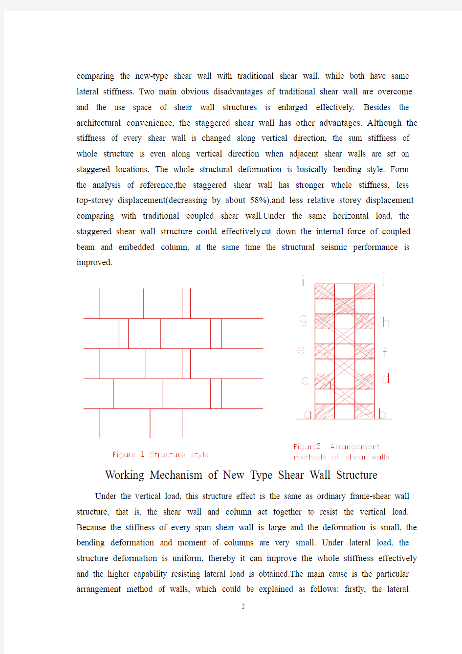
Shear wall structure has been widely used in tall buildings. However, there are still two obvious disadvantages in this structure: first of all, space between two shear wall could not too big and the plane layout is not flexible, so that serviceability requirements are dissatisfied for public buildings; secondly, the bigger dead weight will lead to the increase of constructional materials and seismic force which cause desigh difficulty of super-structures and foundations. In this paper, a new type tall building structure-staggered shear wall structure-is presented in order to overcome above disadvantages of traditional shear wall, which not only provide big space for architectural design but also has lighter dead weight and high capacity of resistance to horizontal load. REINFORCEMENT CONCRETE STAGGERED SHEAR WALL STRUCTURAL SYSTEM IN TALL BUILDINGS Structure Style and Features of New Type Shear Wall Structural System:In this new-type shear wall structural system,every shear wall is at staggered location on adjacent floor, as well as adjacent shear walls are staggered with each other.One end of floor slab is supported on top edge of one shear wall; the other end of floor slab is supported on bottom edge of adjacent shear wall. The edge column and beam are set beside every shear wall. The embedded column and connected beam are set on every floor. The advantage of this structural system is its big use space with small span floor slab.The shear wall arrangement can be staggered or not according to use requirement, shown in Figure 1. As a result, the width of one bay is increased from L to 2L or 3L. In addition, the dead weigh of staggered shear wall is smaller than that of traditional down-to-ground shear wall, so the material cost is reduced. The structural analysis result indicates the wall amount decreases by 25% and the dead weigh decreased by 20%
comparing the new-type shear wall with traditional shear wall, while both have same lateral stiffness. Two main obvious disadvantages of traditional shear wall are overcome and the use space of shear wall structures is enlarged effectively. Besides the architectural convenience, the staggered shear wall has other advantages. Although the stiffness of every shear wall is changed along vertical direction, the sum stiffness of whole structure is even along vertical direction when adjacent shear walls are set on staggered locations. The whole structural deformation is basically bending style. Form the analysis of reference,the staggered shear wall has stronger whole stiffness, less top-storey displacement(decreasing by about 58%),and less relative storey displacement comparing with traditional coupled shear wall.Under the same horizontal load, the staggered shear wall structure could effectively cut down the internal force of coupled beam and embedded column, at the same time the structural seismic performance is improved.
1 2
Working Mechanism of New Type Shear Wall Structure
Under the vertical load, this structure effect is the same as ordinary frame-shear wall structure, that is, the shear wall and column act together to resist the vertical load. Because the stiffness of every span shear wall is large and the deformation is small, the bending deformation and moment of columns are very small. Under lateral load, the structure deformation is uniform, thereby it can improve the whole stiffness effectively and the higher capability resisting lateral load is obtained.The main cause is the particular arrangement method of walls, which could be explained as follows: firstly, the lateral
shearing force transfer mechanism is different from traditional shear wall. The lateral shearing force on top edge of shear wall is transferred to under layer floor slab though the bottom edge of wall, then to under storey adjacent shear wall through the under storey floor slab. At last, the lateral shearing force is transferred to ground floor shear wall and foundation.By this way,the lateral shearing force transfer mechanism is special, in which every floor slab transfer the lateral shearing force of itself floor and above floor.But in traditional shear wall directly. This structure makes the best use of the peculiarity that the slab stiffness is very strong to transfer and resist lateral shear. Although the shear walls are not up bottom in sequence, the slabs which has larger stiffness participate in the work transferring and resisting lateral shear force from the top to the down,from the floor middle part to edge, and from the edge to middle part in whole structure.It corresponds to a space integer structure with large lateral stiffness connected all shear walls by slabs, which have been cut in every story and span. It has been proved in author’s paper that the whole structure will occur integer-bending deformation under lateral force action,while every storey shear walls will occur integer bending without local bending. Secondly, in every piece of staggered shear wall (shown in Figure 2),the shear wall arrangement forms four large X diagonal brace along adcb,cfed, ehgf, gjih (dashed as shown in Figure 2).Because the shear walls forming X diagonal brace have large stiffness and strength, the X diagonal brace stiffness is strong. In addition, both the edge beams and columns around the boundary form bracing ‘frame”with large lateral stiffness. Hence, the structural integer stiffness is greatly improved.
Due to the above main reasons, this structure is considered to have particular advantages compared with traditional shear wall structure in improving structural lateral stiffness. It can provide larger using space, and reduce the material, earthquake action as well as dead weight.Also, it can provide larger lateral stiffness, which will benefit the structural lateral capability. In author’s paper and in this paper the example calculating results indicates that lateral stiffness of this structure are double of coupled shear wall structure ,and nearly equal to integer shear wall structure (light small than the latter).
Aseismic analysis and construction measures in a building
example
In order to study dynamic characteristics and aseismic performances in this structural system, the staggered shear wall will be used as all cross walls in the large bay shear wall structure without internal longitudinal walls.
Example. Thereis a nine-storey reinforcement concrete building, which is large bay shear wall struvture, shown in figure3. here,walls columns, beams, and slabs are all cast-in-situ. The thickness t=240mm is used for shear walls from 1 to 3 stories, while thickness t=200mm is used for shear walls from 4 to 9 stories. Given the section of columns of width b=500mm and depth h=600mm . Given the section of beams of width b=300mm and depth h=700mm . The modulus of elasticity is assumed to be E=2.1*10E7
kN/2m and G=1.05*10E7 kN /2m . The external longitudinal walls are cast-in-situ wall frame, and the cross walls are staggered shear walls , showm in Figure 3 (a) (scheme I) ,intensity 8 zones near earthquake, 2type site ground 。The aseismic analysis is given by using the computer program FWD with wallboard element based on modal ayalysis response spectrum method 。 In order to compare ,the aseismic analysis of others are given at the same time , which are the cross walls used integer walls (scheme 2)and coupled walls (scheme3), shown in Figure 3 (a) and (b) ,respectively. The related results are listed in Table 1 and Table 2, where the seismic shear and displacement are all adopt from the SRSS result of formal three modal shapes.
3
Table1PeriodT(s) top-storey displancement △(cm) bottom seismic shearV(KN)
Wall layout
T1 T2 T3 △ V G V G α= Scheme Ⅰ
0.417 0.128 0.089 0.89 4088.3 56610 0.071 Scheme Ⅱ
0.376 0.110 0.057 0.78 6181.3 67500 0.092 Scheme Ⅲ 0.811 0.205 0.092
1.94 2519.9 60660 0.042
Table 2 Every-story displancement △(cm)
Number of stories SchemeⅠSchemeⅡSchemeⅢ
9 0.890 0.780 1.940
8 0.812 0.695 1.647
7 0.686 0.605 1.381
6 0.604 0.512 1.143
5 0.472 0.415 0.909
4 0.372 0.31
5 0.658
3 0.239 0.220 0.426
2 0.161 0.13
3 0.233
1 0.056 0.059 0.074
From the abve calculated results , it can be observed, firstly , that the building bay increased from 7.2m(scheme 2,3) to 7.2*2=14.4m (scheme 1 ) .Therefore, the useable floor area is increased greatly while dead weight is decreased 2093kN, and concrete of shear walls is saved (40% compared with scheme 2 or about 25% compared with scheme 3). Because the structural stiffness based on the arrangement method of shear walls is uniform, the whole lateral stiffness is increased a lot than that of schene 3 and close to scheme 2 , however, the seismic force is decreased greatly due to the decrease of dead weight ,which reduce the bottom shear coefficient a from 0.092 (scheme 2) to 0.071, thereby it can solve problems in traditional shear wall structures with light increase of the top-storey displancement ( scheme 1 only increases 0.11 cm than scheme 2 ), such as larger bottom shear seismic coefficient . Compared with coupled wall (scheme 3), this structure obviously advances lateral stiffness that the top-storey displancement ?=0.89cm is about 45% of the coupled wall ?=1.94cm .However, the concrete amount and dead weight reduce 25 % than that of coupled wall. This result shows that the new type struvture can adjust the structural stiffness and reduce eigher dead weight or seismic force when the solid shear wall with small opening, which has large stiffness , dead weight , seismic force , and material amount , is dissatisfied because the section of shear
walls and height of coupied beams are limited in design .In this structure, the lateral shear force cannot be transferred to bottom directly but though slabs because the shear walls are cut in ecery storey. Due to the large shear force transferred to the bottom slabs , as a result , the slabs in first storey should be strengthened to ensure that the adequate strength and stiffness would be obtained to transfer the lateral shear force the structure need .
In general, the slabs are cast-in-situ. The concrete used for slabs normally should have grade strength of no less than C20 .The thickness of slabs should not less than 180mm , especially in bottom stories in which the distribution bars are two-way reinforcement ф8 @200. It is emphasized that the shear constructions should be strengthened at the joints-shear walls and slabs . In order to ensure shear strength between walls and slabs ,the wall bars should extend into the above and below spans for a distance according to related Code avout development length .Furthermore, the joint stresses of above and below shear walls are so complex that the shear failure or the lailure caused by the used except the embedded column and connected beam to ensure the joint strength and stiffness. At the above and below walls intersects the fillet measure must be used . Other aseismic constructional details should be carried out in accordance with the Code involved in shear wall structure.
Conclusions
From the above analysis and research, the following conclusions can be drawn : (1) Compare with traditional shear wall structures , the staggered shear wall structure has many advantages, such as providing bigger space and lateral stiffness ,reducing dead weight and seismic force , and saving constructional materials . therefore, this structural system has good economic benefits .
(2) the structural stiffness and deformation is uniform, thereby it can improve the whole stiffness effectively and enable it to appear wholly bending state, which are beneficial to increase the capacity of resistance to horizontal force and ductility.
(3) This structure can reduce the bottom shear seismic coefficient of shear wall structures, thereby it can solve many problems in ordinary shear wall structures , such as bigger space and lateral stiffness , and higher seismic force which will lead to bigger bottom shear seismic coefficient . It also can be a efficient method adjusting structural stiffness and dead weigh in design .
(4)This structure can be used in longitudinal wall of big-space shear wall structure
without inner longitudinal wall, cross shear wall and longitudinal frame structure, and fishy bone big space shear wall structure , because it can provide bigger space and reduce superstructure dead weigh and seismic action without reducing stiffness, which benefit resistance either ground floor frame-supported shear wall or whole structure.
(5) This structure can be used in non-seismic regions and has good effect because it can provide bigger lateral stiffness than ordinary shear wall structures, which have the same amount of shear walls. So it is beneficial to resist wind loads. Where specific aseismic design and construction measure are taken, it can be used in intensity 7 or 8 seismic zones.
(6) Alternate-floor shear wall structure has been used overseas in practical engineering and has good effect. However, it can only be used in the single-span structures. The staggered shear wall structure presented in this paper can be used in the multi-span structures, which has better behaviors of stiffness uniformity along the height and deformation than the former.
This new type structural system of tall buildings needs further research, especially need to be checked by model experiments and engineering practices.
新型高层建筑物结构交错排列剪力墙结构
引言
剪力墙结构在高层建筑用途广泛。然而,在这个结构中仍然有二个明显的缺点:首先,二个剪力墙之间的空间不可能太大,并且平面布局不灵活,因此不满足公共建筑的操作性能要求; 第二,更大的自重将导致建设材料和地震力的增大从而造成结构和基础设计困难。在本文,为了克服普通剪力墙的缺点介绍一个新型高层建筑结构交错排列的剪力墙结构,不仅为建筑设计提供大空间,而且对水平作用力的抵抗有更轻自重和抵抗力。
交错排列剪力墙结构系统在高层建筑中的具体优点新型剪力墙结构系统样式和特点:在这个新型剪力墙结构系统,每个剪力墙的交错排列地点设在毗邻地板上,并且毗邻剪力墙相互交错排列. 一剪力墙上缘支撑地面板的一个末端; 毗邻剪力墙下缘支撑地面板的另一个末端。在每个剪力墙旁边设置边柱和梁。在每个地面板上设置嵌入柱和连系梁。这个结构系统的好处是它的空间用途大和板的间距小。剪力墙可以交错排列或不符合使用要求,见图1。结果,间隔宽度从L被增加到2L或3L。. . 另外,交错排列的剪力墙自重小于普通剪力墙,因此减少物质费用。结构分析结果表明新型剪力墙与普通剪力墙相比,在两者有同样侧向刚度时,墙壁数减退25%和自重减少20%。不仅克服了普通剪力墙的二个主要明显的缺点,并且有效地扩大剪力墙结构用途空间。除了建筑便利以外,交错排列的剪力墙还有其他好处。虽然每个剪力墙的刚度变形沿垂直的方向,当毗邻剪力墙在交错排列地点受力时,整体结构的总刚度变形沿垂直的方向。整体结构变形基本上弯曲形式。以上分析表明,交错排列的剪力墙和普通剪力墙相比有更强的整体刚度、较少的上面层位移(减少大约58%)和较少的相对楼层位移。在同一水平力之下,交错排列剪力墙结构能有效地减少梁和柱的内力,并且在地震时提高结构的性能。
新型剪力墙结构工作方法
在垂直力作用下,这个结构作用和普通框架结构一样,剪力墙和柱一起抵抗垂直力。由于每个剪力墙的刚度大,并且变形小,柱的弯曲的变形和弯曲时间是非常小的。在侧向力作用下,结构变形是一致的,从而它可能有效地改进整体刚度,
并且能更好的抵抗侧向力。主要原因是剪力墙的特殊布置方法,可以解释如下:首先,侧向剪切力传递方法是与传统剪力墙不同。侧向剪切力通过墙壁下缘从剪力墙上缘转移到下层楼板,然后通过下面楼板到下面楼层毗邻剪力墙。最后,侧向剪切力转移到基层剪力墙和基础。由此可知,侧向剪切力传递方法是特别的,每个楼板通过楼板和上层楼板传递侧向剪切力。但在传统剪力墙结构中,每个楼板只传递自身的侧向剪力。横向剪切力通过剪力墙直接传递给基础。这个结构充分利用板的大刚度来传递并且抵抗横向剪力。虽然剪力墙底部排列不规则,但在整体结构中,楼板有更大的刚度,它传递和抵抗从上到下的侧向剪力,从地板中间渐近或从边缘到中间的侧向剪力。它相当于空间整体结构有了大侧向刚度,它通过楼板连接被楼层和跨度隔开的所有剪力墙。在作者的文章中证明了在侧向力作用下整体结构将发生整体弯曲变形,而每个楼层剪力墙将发生弯曲,不会发生局部弯曲。
图2 剪力墙的布置方法
图1 结构形式
第二,在交错排列的剪力墙每个部分(如图2所示),剪力墙沿对角线adcb,cfed,ehgf,gjih排列成四个X形(如图2所示)。由于形成X对角线,剪力墙有大刚度和强度,X对角线具有教大的刚度。另外,边柱和梁形成了具有教大侧向刚度的支撑--`框架”。因此,很大地增强结构整体刚度。由于上述主要原因,这个结构与普通剪力墙结构相比,在增强结构侧向刚度方面有特殊的意义。它可以扩大使用空间,并且减少材料,在地震作用时减轻自重。并且,它可能提供更大的侧向刚度,有益于增强结构侧向能力。在作者的想法和本文例子的计算的结果表明这个结构通过连接两个剪力墙产生的侧向刚度几乎和整体剪力墙结构相同(比后者轻)。
在大厦这个例子中的抗震分析和建筑措施
为了学习这个结构系统的力学性能和抗震能力,交错排列的剪力墙在结构不使用内纵墙的情况下将被用于大跨度结构的横墙。
例子。有一个九层的混凝土建筑,是跨度剪力墙结构,如上图3所示。这里,墙、柱、梁和楼板全部采用现浇。从1到3层使用厚度t=240mm的剪力墙,从4到9层使用厚度t=200mm剪力墙。假如柱的宽度b=500mm,高度h=600mm。假如梁的宽度b=300mm,高度h=700mm。假设弹性模量E=2.110E7 kN/㎡和G=1.05×10E7 kN/㎡。如上图3 (a) 所示(方案Ⅰ),8度震区,2类地面附近,外纵墙被浇注框架中,并且横墙是交错排列的剪力墙。在分析反应光谱方法分析墙板元素的基础上,使用计算机程序FWD计算抗震的分析。为了比较,在上图3 (a)和(b)同时给出了其它的抗震的分析,分别显示横墙使用的整体墙(方案2)和联肢墙(方案3)。
相关结果在表1和表2中列出,地震作用力和位移全部从SRSS结果中采取。
图3 墙的布置
表一周期T(s),顶点位移△(cm),底部剪力V(KN)
墙的布置T1 T2 T3 △V G V
α=
G
方案Ⅰ0.417 0.128 0.089 0.89 4088.3 56610 0.071
方案Ⅱ0.376 0.110 0.057 0.78 6181.3 67500 0.092
方案Ⅲ0.811 0.205 0.092 1.94 2519.9 60660 0.042
表二各层位移
层号方案Ⅰ方案Ⅱ方案Ⅲ
9 0.890 0.780 1.940
8 0.812 0.695 1.647
7 0.686 0.605 1.381
建筑结构设计中英文对照外文翻译文献
中英文对照外文翻译 (文档含英文原文和中文翻译) Create and comprehensive technology in the structure global design of the building The 21st century will be the era that many kinds of disciplines technology coexists , it will form the enormous motive force of promoting the development of building , the building is more and more important too in global design, the architect must seize the opportunity , give full play to the architect's leading role, preside over every building engineering design well. Building there is the global design concept not new of architectural design,characteristic of it for in an all-round way each element not correlated with building- there aren't external environment condition, building , technical equipment,etc. work in coordination with, and create the premium building with the comprehensive new technology to combine together. The premium building is created, must consider sustainable development , namely future requirement , in other words, how save natural resources as much as possible, how about protect the environment that the mankind depends on for existence, how construct through high-quality between architectural design and building, in order to reduce building equipment use quantity and
中英文参考文献格式
中文参考文献格式 参考文献(即引文出处)的类型以单字母方式标识: M——专著,C——论文集,N——报纸文章,J——期刊文章,D——学位论文,R——报告,S——标准,P——专利;对于不属于上述的文献类型,采用字母“Z”标识。 参考文献一律置于文末。其格式为: (一)专著 示例 [1] 张志建.严复思想研究[M]. 桂林:广西师范大学出版社,1989. [2] 马克思恩格斯全集:第1卷[M]. 北京:人民出版社,1956. [3] [英]蔼理士.性心理学[M]. 潘光旦译注.北京:商务印书馆,1997. (二)论文集 示例 [1] 伍蠡甫.西方文论选[C]. 上海:上海译文出版社,1979. [2] 别林斯基.论俄国中篇小说和果戈里君的中篇小说[A]. 伍蠡甫.西方文论选:下册[C]. 上海:上海译文出版社,1979. 凡引专著的页码,加圆括号置于文中序号之后。 (三)报纸文章 示例 [1] 李大伦.经济全球化的重要性[N]. 光明日报,1998-12-27,(3) (四)期刊文章 示例 [1] 郭英德.元明文学史观散论[J]. 北京师范大学学报(社会科学版),1995(3). (五)学位论文 示例 [1] 刘伟.汉字不同视觉识别方式的理论和实证研究[D]. 北京:北京师范大学心理系,1998. (六)报告 示例 [1] 白秀水,刘敢,任保平. 西安金融、人才、技术三大要素市场培育与发展研究[R]. 西安:陕西师范大学西北经济发展研究中心,1998. (七)、对论文正文中某一特定内容的进一步解释或补充说明性的注释,置于本页地脚,前面用圈码标识。 参考文献的类型 根据GB3469-83《文献类型与文献载体代码》规定,以单字母标识: M——专著(含古籍中的史、志论著) C——论文集 N——报纸文章 J——期刊文章 D——学位论文 R——研究报告 S——标准 P——专利 A——专著、论文集中的析出文献 Z——其他未说明的文献类型 电子文献类型以双字母作为标识: DB——数据库 CP——计算机程序 EB——电子公告
信息与计算科学中英文对照外文翻译文献
(文档含英文原文和中文翻译) 中英文对照外文翻译 基于拉格朗日乘数法的框架结构合理线刚度比的研究 【摘要】框架结构是一种常见的多层高层建筑结构;列的合理线刚度比研究是框架结构优化设计中的一个重要方面。本论文研究合理线刚度比时,框架梁、柱的
侧移刚度根据拉格朗日乘数法结构优化的理论和在框架梁、柱的总物质的量一定的前提下,取得最高值。与传统的估计方法和试算梁柱截面尺寸不同,梁、柱的合理的截面尺寸可以在初步设计阶段由派生的公式计算。这种方法不仅作为计算框架梁、柱的截面尺寸基础,确认初步设计阶,而且也被用做类似的结构梁柱合理线刚度比研究的参考。此外,在调整帧梁、柱的截面尺寸的方法的基础上,降低柱的轴向的压缩比,从而达到剪切压缩比和提高结构的延展性。 【关键词】拉格朗日数乘法框架结构刚度比截面尺寸 1 引言 在混凝土框架结构初步设计的期间,通常,框架梁截面高度通过跨度来估算,和截面宽度根据高宽比估算; 框架柱的截面尺寸是根据柱轴压缩的支持柱的面积的比率估算[1]。然而,在估计过程中,初步设计阶段中的一个重要的链,未考虑到柱侧移刚度的影响[2]。列侧移刚度越大,结构层间位的刚度越大,剪切型框架结构的层间位移将越较小。所以,总结构越小的侧向位移将减少地震灾害[3] 所造成的损失。论文的核心是如何得到列侧移刚度的最大值。 同时,列侧移刚度的值与框架梁-柱线刚度直接相关。本论文的目的是为了得到一个合理的框架梁 - 柱的线刚度比,在某个控制范围内获得列侧移刚度的最大值。 计算列横向位移的方法有两种方法:刚度拐点点法和修改拐点法。拐点的方法假定关节的旋转角度为0(当梁柱线性刚度比是大于或等于3时,柱的上端和下端的关节的旋转角度可以取为0,因为它实际上是相当小),即梁的弯曲刚性被视为无穷大。拐点的方法主要是应用于具有比较少层的框架结构。但对于多层、高层框架结构,增加柱截面会导致梁柱线刚度比小于3,在水平荷载作用下,框架结构的所有关节的旋转角度的横向位移会发生不可忽视。因此,一位日本教授武藤提出修改拐点法[4],即D-值方法。本文采用D-值列侧移刚度的计算法,因为它着重于多层、高层框架结构。 少数在国内外对框架梁柱合理线刚度比的研究,只有梁七黹,源于列侧移刚度的计算方法,比D-值法更加应用广泛;申得氏指出在多层、高层框架结构的柱侧向刚度计算中存在的问题,补充和修改底部和顶部层的列侧向刚度计算公式;
毕业设计外文翻译资料
外文出处: 《Exploiting Software How to Break Code》By Greg Hoglund, Gary McGraw Publisher : Addison Wesley Pub Date : February 17, 2004 ISBN : 0-201-78695-8 译文标题: JDBC接口技术 译文: JDBC是一种可用于执行SQL语句的JavaAPI(ApplicationProgrammingInterface应用程序设计接口)。它由一些Java语言编写的类和界面组成。JDBC为数据库应用开发人员、数据库前台工具开发人员提供了一种标准的应用程序设计接口,使开发人员可以用纯Java语言编写完整的数据库应用程序。 一、ODBC到JDBC的发展历程 说到JDBC,很容易让人联想到另一个十分熟悉的字眼“ODBC”。它们之间有没有联系呢?如果有,那么它们之间又是怎样的关系呢? ODBC是OpenDatabaseConnectivity的英文简写。它是一种用来在相关或不相关的数据库管理系统(DBMS)中存取数据的,用C语言实现的,标准应用程序数据接口。通过ODBCAPI,应用程序可以存取保存在多种不同数据库管理系统(DBMS)中的数据,而不论每个DBMS使用了何种数据存储格式和编程接口。 1.ODBC的结构模型 ODBC的结构包括四个主要部分:应用程序接口、驱动器管理器、数据库驱动器和数据源。应用程序接口:屏蔽不同的ODBC数据库驱动器之间函数调用的差别,为用户提供统一的SQL编程接口。 驱动器管理器:为应用程序装载数据库驱动器。 数据库驱动器:实现ODBC的函数调用,提供对特定数据源的SQL请求。如果需要,数据库驱动器将修改应用程序的请求,使得请求符合相关的DBMS所支持的文法。 数据源:由用户想要存取的数据以及与它相关的操作系统、DBMS和用于访问DBMS的网络平台组成。 虽然ODBC驱动器管理器的主要目的是加载数据库驱动器,以便ODBC函数调用,但是数据库驱动器本身也执行ODBC函数调用,并与数据库相互配合。因此当应用系统发出调用与数据源进行连接时,数据库驱动器能管理通信协议。当建立起与数据源的连接时,数据库驱动器便能处理应用系统向DBMS发出的请求,对分析或发自数据源的设计进行必要的翻译,并将结果返回给应用系统。 2.JDBC的诞生 自从Java语言于1995年5月正式公布以来,Java风靡全球。出现大量的用java语言编写的程序,其中也包括数据库应用程序。由于没有一个Java语言的API,编程人员不得不在Java程序中加入C语言的ODBC函数调用。这就使很多Java的优秀特性无法充分发挥,比如平台无关性、面向对象特性等。随着越来越多的编程人员对Java语言的日益喜爱,越来越多的公司在Java程序开发上投入的精力日益增加,对java语言接口的访问数据库的API 的要求越来越强烈。也由于ODBC的有其不足之处,比如它并不容易使用,没有面向对象的特性等等,SUN公司决定开发一Java语言为接口的数据库应用程序开发接口。在JDK1.x 版本中,JDBC只是一个可选部件,到了JDK1.1公布时,SQL类包(也就是JDBCAPI)
土木工程外文文献翻译
专业资料 学院: 专业:土木工程 姓名: 学号: 外文出处:Structural Systems to resist (用外文写) Lateral loads 附件:1.外文资料翻译译文;2.外文原文。
附件1:外文资料翻译译文 抗侧向荷载的结构体系 常用的结构体系 若已测出荷载量达数千万磅重,那么在高层建筑设计中就没有多少可以进行极其复杂的构思余地了。确实,较好的高层建筑普遍具有构思简单、表现明晰的特点。 这并不是说没有进行宏观构思的余地。实际上,正是因为有了这种宏观的构思,新奇的高层建筑体系才得以发展,可能更重要的是:几年以前才出现的一些新概念在今天的技术中已经变得平常了。 如果忽略一些与建筑材料密切相关的概念不谈,高层建筑里最为常用的结构体系便可分为如下几类: 1.抗弯矩框架。 2.支撑框架,包括偏心支撑框架。 3.剪力墙,包括钢板剪力墙。 4.筒中框架。 5.筒中筒结构。 6.核心交互结构。 7. 框格体系或束筒体系。 特别是由于最近趋向于更复杂的建筑形式,同时也需要增加刚度以抵抗几力和地震力,大多数高层建筑都具有由框架、支撑构架、剪力墙和相关体系相结合而构成的体系。而且,就较高的建筑物而言,大多数都是由交互式构件组成三维陈列。 将这些构件结合起来的方法正是高层建筑设计方法的本质。其结合方式需要在考虑环境、功能和费用后再发展,以便提供促使建筑发展达到新高度的有效结构。这并
不是说富于想象力的结构设计就能够创造出伟大建筑。正相反,有许多例优美的建筑仅得到结构工程师适当的支持就被创造出来了,然而,如果没有天赋甚厚的建筑师的创造力的指导,那么,得以发展的就只能是好的结构,并非是伟大的建筑。无论如何,要想创造出高层建筑真正非凡的设计,两者都需要最好的。 虽然在文献中通常可以见到有关这七种体系的全面性讨论,但是在这里还值得进一步讨论。设计方法的本质贯穿于整个讨论。设计方法的本质贯穿于整个讨论中。 抗弯矩框架 抗弯矩框架也许是低,中高度的建筑中常用的体系,它具有线性水平构件和垂直构件在接头处基本刚接之特点。这种框架用作独立的体系,或者和其他体系结合起来使用,以便提供所需要水平荷载抵抗力。对于较高的高层建筑,可能会发现该本系不宜作为独立体系,这是因为在侧向力的作用下难以调动足够的刚度。 我们可以利用STRESS,STRUDL 或者其他大量合适的计算机程序进行结构分析。所谓的门架法分析或悬臂法分析在当今的技术中无一席之地,由于柱梁节点固有柔性,并且由于初步设计应该力求突出体系的弱点,所以在初析中使用框架的中心距尺寸设计是司空惯的。当然,在设计的后期阶段,实际地评价结点的变形很有必要。 支撑框架 支撑框架实际上刚度比抗弯矩框架强,在高层建筑中也得到更广泛的应用。这种体系以其结点处铰接或则接的线性水平构件、垂直构件和斜撑构件而具特色,它通常与其他体系共同用于较高的建筑,并且作为一种独立的体系用在低、中高度的建筑中。
中英文论文参考文献标准格式 超详细
超详细中英文论文参考文献标准格式 1、参考文献和注释。按论文中所引用文献或注释编号的顺序列在论文正文之后,参考文献之前。图表或数据必须注明来源和出处。 (参考文献是期刊时,书写格式为: [编号]、作者、文章题目、期刊名(外文可缩写)、年份、卷号、期数、页码。参考文献是图书时,书写格式为: [编号]、作者、书名、出版单位、年份、版次、页码。) 2、附录。包括放在正文内过份冗长的公式推导,以备他人阅读方便所需的辅助性数学工具、重复性数据图表、论文使用的符号意义、单位缩写、程序全文及有关说明等。 参考文献(即引文出处)的类型以单字母方式标识,具体如下: [M]--专著,著作 [C]--论文集(一般指会议发表的论文续集,及一些专题论文集,如《***大学研究生学术论文集》[N]-- 报纸文章 [J]--期刊文章:发表在期刊上的论文,尽管有时我们看到的是从网上下载的(如知网),但它也是发表在期刊上的,你看到的电子期刊仅是其电子版 [D]--学位论文:不区分硕士还是博士论文 [R]--报告:一般在标题中会有"关于****的报告"字样 [S]-- 标准 [P]--专利 [A]--文章:很少用,主要是不属于以上类型的文章 [Z]--对于不属于上述的文献类型,可用字母"Z"标识,但这种情况非常少见 常用的电子文献及载体类型标识: [DB/OL] --联机网上数据(database online) [DB/MT] --磁带数据库(database on magnetic tape) [M/CD] --光盘图书(monograph on CDROM) [CP/DK] --磁盘软件(computer program on disk) [J/OL] --网上期刊(serial online) [EB/OL] --网上电子公告(electronic bulletin board online) 很显然,标识的就是该资源的英文缩写,/前面表示类型,/后面表示资源的载体,如OL表示在线资源 二、参考文献的格式及举例 1.期刊类 【格式】[序号]作者.篇名[J].刊名,出版年份,卷号(期号)起止页码. 【举例】 [1] 周融,任志国,杨尚雷,厉星星.对新形势下毕业设计管理工作的思考与实践[J].电气电子教学学报,2003(6):107-109. [2] 夏鲁惠.高等学校毕业设计(论文)教学情况调研报告[J].高等理科教育,2004(1):46-52. [3] Heider, E.R.& D.C.Oliver. The structure of color space in naming and memory of two languages [J]. Foreign Language Teaching and Research, 1999, (3): 62 67. 2.专著类
毕业设计外文翻译附原文
外文翻译 专业机械设计制造及其自动化学生姓名刘链柱 班级机制111 学号1110101102 指导教师葛友华
外文资料名称: Design and performance evaluation of vacuum cleaners using cyclone technology 外文资料出处:Korean J. Chem. Eng., 23(6), (用外文写) 925-930 (2006) 附件: 1.外文资料翻译译文 2.外文原文
应用旋风技术真空吸尘器的设计和性能介绍 吉尔泰金,洪城铱昌,宰瑾李, 刘链柱译 摘要:旋风型分离器技术用于真空吸尘器 - 轴向进流旋风和切向进气道流旋风有效地收集粉尘和降低压力降已被实验研究。优化设计等因素作为集尘效率,压降,并切成尺寸被粒度对应于分级收集的50%的效率进行了研究。颗粒切成大小降低入口面积,体直径,减小涡取景器直径的旋风。切向入口的双流量气旋具有良好的性能考虑的350毫米汞柱的低压降和为1.5μm的质量中位直径在1米3的流量的截止尺寸。一使用切向入口的双流量旋风吸尘器示出了势是一种有效的方法,用于收集在家庭中产生的粉尘。 摘要及关键词:吸尘器; 粉尘; 旋风分离器 引言 我们这个时代的很大一部分都花在了房子,工作场所,或其他建筑,因此,室内空间应该是既舒适情绪和卫生。但室内空气中含有超过室外空气因气密性的二次污染物,毒物,食品气味。这是通过使用产生在建筑中的新材料和设备。真空吸尘器为代表的家电去除有害物质从地板到地毯所用的商用真空吸尘器房子由纸过滤,预过滤器和排气过滤器通过洁净的空气排放到大气中。虽然真空吸尘器是方便在使用中,吸入压力下降说唱空转成比例地清洗的时间,以及纸过滤器也应定期更换,由于压力下降,气味和细菌通过纸过滤器内的残留粉尘。 图1示出了大气气溶胶的粒度分布通常是双峰形,在粗颗粒(>2.0微米)模式为主要的外部来源,如风吹尘,海盐喷雾,火山,从工厂直接排放和车辆废气排放,以及那些在细颗粒模式包括燃烧或光化学反应。表1显示模式,典型的大气航空的直径和质量浓度溶胶被许多研究者测量。精细模式在0.18?0.36 在5.7到25微米尺寸范围微米尺寸范围。质量浓度为2?205微克,可直接在大气气溶胶和 3.85至36.3μg/m3柴油气溶胶。
框架结构设计外文翻译
毕业设计(论文)外文资料翻译 系:机械工程系 专业:土木工程 姓名: 学号: 外文出处:Design of prestressed (用外文写) concrete structures 附件: 1.外文资料翻译译文;2.外文原文。
附件1:外文资料翻译译文 8-2简支梁布局 一个简单的预应力混凝土梁由两个危险截面控制:最大弯矩截面和端截面。这两部分设计好之后,中间截面一定要单独检查,必要时其他部位也要单独调查。最大弯矩截面在以下两种荷载阶段为控制情况,即传递时梁受最小弯矩M G的初始阶段和最大设计弯矩M T时的工作荷载阶段。而端截面则由抗剪强度、支承垫板、锚头间距和千斤顶净空所需要的面积来决定。所有的中间截面是由一个或多个上述要求,根它们与上述两种危险截面的距离来控制。对于后张构件的一种常见的布置方式是在最大弯矩截面采用诸如I形或T形的截面,而在接近梁端处逐渐过渡到简单的矩形截面。这就是人们通常所说的后张构件的端块。对于用长线法生产的先张构件,为了便于生产,全部只用一种等截面,其截面形状则可以为I形、双T形或空心的。在第5 、 6 和7章节中已经阐明了个别截面的设计,下面论述简支梁钢索的总布置。 梁的布置可以用变化混凝土和钢筋的办法来调整。混凝土的截面在高度、宽度、形状和梁底面或者顶面的曲率方面都可以有变化。而钢筋只在面积方面有所变化,不过在相对于混凝土重心轴线的位置方面却多半可以有变化。通过调整这些变化因素,布置方案可能有许多组合,以适应不同的荷载情况。这一点是与钢筋混凝土梁是完全不同的,在钢筋混凝土梁的通常布置中,不是一个统一的矩形截面便是一个统一的T形,而钢筋的位置总是布置得尽量靠底面纤维。 首先考虑先张梁,如图 8-7,这里最好采用直线钢索,因为它们在两个台座之间加力比较容易。我们先从图(a)的等截面直梁的直线钢索开始讨论。这样的布置都很简单,但这样一来,就不是很经济的设计了,因为跨中和梁端的要求会产生冲突。通常发生在跨度中央的最大弯矩截面中的钢索,最好尽量放低,以便尽可能提供最大力臂而提供最大的内部抵制力矩。当跨度中央的梁自重弯矩M G相当大时,就可以把c.g.s布置在截面核心范围以下很远的地方,而不致在传递时在顶部纤维中引起拉应力。然而对于梁端截面却有一套完全不同的要求。由于在梁端没有外力矩,因为在最后的时刻,安排钢索要以c.g.s与 c.g.c在结束区段一致,如此同样地获得克服压力分配的方法。无论如何,如果张应力在最后不能承受,放置 c.g.s.
中英文参考文献格式
中英文参考文献格式! (細節也很重要啊。。)来源:李菲玥的日志 规范的参考文献格式 一、参考文献的类型 参考文献(即引文出处)的类型以单字母方式标识,具体如下: M——专著C——论文集N——报纸文章J——期刊文章 D——学位论文R——报告S——标准P——专利 A——文章 对于不属于上述的文献类型,采用字母“Z”标识。 常用的电子文献及载体类型标识: [DB/OL]——联机网上数据(database online) [DB/MT]——磁带数据库(database on magnetic tape) [M/CD]——光盘图书(monograph on CD ROM) [CP/DK]——磁盘软件(computer program on disk) [J/OL]——网上期刊(serial online) [EB/OL]——网上电子公告(electronic bulletin board online) 对于英文参考文献,还应注意以下两点: ①作者姓名采用“姓在前名在后”原则,具体格式是:姓,名字的首字母. 如:Malcolm R ichard Cowley 应为:Cowley, M.R.,如果有两位作者,第一位作者方式不变,&之后第二位作者名字的首字母放在前面,姓放在后面,如:Frank Norris 与Irving Gordon应为:Norri s, F. & I.Gordon.; ②书名、报刊名使用斜体字,如:Mastering English Literature,English Weekly。二、参考文献的格式及举例 1.期刊类 【格式】[序号]作者.篇名[J].刊名,出版年份,卷号(期号):起止页码. 【举例】 [1] 周融,任志国,杨尚雷,厉星星.对新形势下毕业设计管理工作的思考与实践[J].电气电子教学学报,2003(6):107-109.
毕业设计外文翻译
毕业设计(论文) 外文翻译 题目西安市水源工程中的 水电站设计 专业水利水电工程 班级 学生 指导教师 2016年
研究钢弧形闸门的动态稳定性 牛志国 河海大学水利水电工程学院,中国南京,邮编210098 nzg_197901@https://www.360docs.net/doc/ed14097592.html,,niuzhiguo@https://www.360docs.net/doc/ed14097592.html, 李同春 河海大学水利水电工程学院,中国南京,邮编210098 ltchhu@https://www.360docs.net/doc/ed14097592.html, 摘要 由于钢弧形闸门的结构特征和弹力,调查对参数共振的弧形闸门的臂一直是研究领域的热点话题弧形弧形闸门的动力稳定性。在这个论文中,简化空间框架作为分析模型,根据弹性体薄壁结构的扰动方程和梁单元模型和薄壁结构的梁单元模型,动态不稳定区域的弧形闸门可以通过有限元的方法,应用有限元的方法计算动态不稳定性的主要区域的弧形弧形闸门工作。此外,结合物理和数值模型,对识别新方法的参数共振钢弧形闸门提出了调查,本文不仅是重要的改进弧形闸门的参数振动的计算方法,但也为进一步研究弧形弧形闸门结构的动态稳定性打下了坚实的基础。 简介 低举升力,没有门槽,好流型,和操作方便等优点,使钢弧形闸门已经广泛应用于水工建筑物。弧形闸门的结构特点是液压完全作用于弧形闸门,通过门叶和主大梁,所以弧形闸门臂是主要的组件确保弧形闸门安全操作。如果周期性轴向载荷作用于手臂,手臂的不稳定是在一定条件下可能发生。调查指出:在弧形闸门的20次事故中,除了极特殊的破坏情况下,弧形闸门的破坏的原因是弧形闸门臂的不稳定;此外,明显的动态作用下发生破坏。例如:张山闸,位于中国的江苏省,包括36个弧形闸门。当一个弧形闸门打开放水时,门被破坏了,而其他弧形闸门则关闭,受到静态静水压力仍然是一样的,很明显,一个动态的加载是造成的弧形闸门破坏一个主要因素。因此弧形闸门臂的动态不稳定是造成弧形闸门(特别是低水头的弧形闸门)破坏的主要原是毫无疑问。
英文引用及参考文献格式要求
英文引用及参考文献格式要求 一、参考文献的类型 参考文献(即引文出处)的类型以单字母方式标识,具体如下: M——专著C——论文集N——报纸文章 J——期刊文章D——学位论文R——报告 对于不属于上述的文献类型,采用字母“Z”标识。 对于英文参考文献,还应注意以下两点: ①作者姓名采用“姓在前名在后”原则,具体格式是:姓,名字的首字母.如:MalcolmRichardCowley应为:Cowley,M.R.,如果有两位作者,第一位作者方式不变,&之后第二位作者名字的首字母放在前面,姓放在后面,如:FrankNorris与IrvingGordon应为:Norris,F.&I.Gordon.; ②书名、报刊名使用斜体字,如:MasteringEnglishLiterature,EnglishWeekly。 二、参考文献的格式及举例 1.期刊类 【格式】[序号]作者.篇名[J].刊名,出版年份,卷号(期号):起止页码. 【举例】 [1]王海粟.浅议会计信息披露模式[J].财政研究,2004,21(1):56-58. [2]夏鲁惠.高等学校毕业论文教学情况调研报告[J].高等理科教育,2004(1):46-52. [3]Heider,E.R.&D.C.Oliver.Thestructureofcolorspaceinnamingandmemo ryoftwolanguages[J].ForeignLanguageTeachingandResearch,1999,(3):62–6 7. 2.专著类 【格式】[序号]作者.书名[M].出版地:出版社,出版年份:起止页码. 【举例】[4]葛家澍,林志军.现代西方财务会计理论[M].厦门:厦门大学出版社,2001:42. [5]Gill,R.MasteringEnglishLiterature[M].London:Macmillan,1985:42-45. 3.报纸类 【格式】[序号]作者.篇名[N].报纸名,出版日期(版次). 【举例】 [6]李大伦.经济全球化的重要性[N].光明日报,1998-12-27(3). [7]French,W.BetweenSilences:AVoicefromChina[N].AtlanticWeekly,198 715(33). 4.论文集 【格式】[序号]作者.篇名[C].出版地:出版者,出版年份:起始页码. 【举例】 [8]伍蠡甫.西方文论选[C].上海:上海译文出版社,1979:12-17. [9]Spivak,G.“CantheSubalternSpeak?”[A].InC.Nelson&L.Grossberg(e ds.).VictoryinLimbo:Imigism[C].Urbana:UniversityofIllinoisPress,1988, pp.271-313.
毕业设计外文翻译
毕业设计(论文) 外文文献翻译 题目:A new constructing auxiliary function method for global optimization 学院: 专业名称: 学号: 学生姓名: 指导教师: 2014年2月14日
一个新的辅助函数的构造方法的全局优化 Jiang-She Zhang,Yong-Jun Wang https://www.360docs.net/doc/ed14097592.html,/10.1016/j.mcm.2007.08.007 非线性函数优化问题中具有许多局部极小,在他们的搜索空间中的应用,如工程设计,分子生物学是广泛的,和神经网络训练.虽然现有的传统的方法,如最速下降方法,牛顿法,拟牛顿方法,信赖域方法,共轭梯度法,收敛迅速,可以找到解决方案,为高精度的连续可微函数,这在很大程度上依赖于初始点和最终的全局解的质量很难保证.在全局优化中存在的困难阻碍了许多学科的进一步发展.因此,全局优化通常成为一个具有挑战性的计算任务的研究. 一般来说,设计一个全局优化算法是由两个原因造成的困难:一是如何确定所得到的最小是全球性的(当时全球最小的是事先不知道),和其他的是,如何从中获得一个更好的最小跳.对第一个问题,一个停止规则称为贝叶斯终止条件已被报道.许多最近提出的算法的目标是在处理第二个问题.一般来说,这些方法可以被类?主要分两大类,即:(一)确定的方法,及(ii)的随机方法.随机的方法是基于生物或统计物理学,它跳到当地的最低使用基于概率的方法.这些方法包括遗传算法(GA),模拟退火法(SA)和粒子群优化算法(PSO).虽然这些方法有其用途,它们往往收敛速度慢和寻找更高精度的解决方案是耗费时间.他们更容易实现和解决组合优化问题.然而,确定性方法如填充函数法,盾构法,等,收敛迅速,具有较高的精度,通常可以找到一个解决方案.这些方法往往依赖于修改目标函数的函数“少”或“低”局部极小,比原来的目标函数,并设计算法来减少该?ED功能逃离局部极小更好的发现. 引用确定性算法中,扩散方程法,有效能量的方法,和积分变换方法近似的原始目标函数的粗结构由一组平滑函数的极小的“少”.这些方法通过修改目标函数的原始目标函数的积分.这样的集成是实现太贵,和辅助功能的最终解决必须追溯到
框架结构外文翻译
南京工程学院毕业设计 外文资料翻译 学生姓名:顾建祥 学号: 240095319 班级名称: K建工ZB093 所在院系:康尼学院
Underground Space Utilization The rapid growth of world civilization will have a significant impact on the way humans live in the future. As the global population increases and more countries demand a higher standard of living, the difficulty of doing this is compounded by three broad trends: the conversion of agricultural land to development uses; the increasing urbanization of the world`s population; and growing concern for the maintenance and improvement of the environment, especially regarding global warming and the impact of population growth. Underground space utilization, as this chapter describes, offers opportunities for helping address these trends. By moving certain facilities and function underground, surface land in urban areas can be used more effectively , thus freeing space for agricultural and recreational purpose. Similarly, the use of terraced earth sheltered housing. Using underground space also enables humans to live more comfortably in densely populated areas while improving the quality of live. On an urban or local level, the use of underground facilities is rising to accommodate the complex demands of today`s society while improving the environment . For example, both urban and rural areas are requiring improved transportation, utility, and recreational services. The state of traffic congestion in many urban areas of the world is at a critical level for the support of basic human living, and it is difficult if not impossible to add new infrastructure at ground level without causing an unacceptable deterioration of the surface environment or an unacceptable relocation of existing land uses and neighborhoods. On a national level in countries around the world, global trends are causing the creation and extension of mining developments and oil or gas recovery at greater depths and in more inaccessible or sensitive locations. Three trends have also led to the developments of improved designs for
毕业设计外文翻译格式实例.
理工学院毕业设计(论文)外文资料翻译 专业:热能与动力工程 姓名:赵海潮 学号:09L0504133 外文出处:Applied Acoustics, 2010(71):701~707 附件: 1.外文资料翻译译文;2.外文原文。
附件1:外文资料翻译译文 基于一维CFD模型下汽车排气消声器的实验研究与预测Takeshi Yasuda, Chaoqun Wua, Noritoshi Nakagawa, Kazuteru Nagamura 摘要目前,利用实验和数值分析法对商用汽车消声器在宽开口喉部加速状态下的排气噪声进行了研究。在加热工况下发动机转速从1000转/分钟加速到6000转/分钟需要30秒。假定其排气消声器的瞬时声学特性符合一维计算流体力学模型。为了验证模拟仿真的结果,我们在符合日本工业标准(JIS D 1616)的消声室内测量了排气消声器的瞬态声学特性,结果发现在二阶发动机转速频率下仿真结果和实验结果非常吻合。但在发动机高阶转速下(从5000到6000转每分钟的四阶转速,从4200到6000转每分钟的六阶转速这样的高转速范围内),计算结果和实验结果出现了较大差异。根据结果分析,差异的产生是由于在模拟仿真中忽略了流动噪声的影响。为了满足市场需求,研究者在一维计算流体力学模型的基础上提出了一个具有可靠准确度的简化模型,相对标准化模型而言该模型能节省超过90%的执行时间。 关键字消声器排气噪声优化设计瞬态声学性能 1 引言 汽车排气消声器广泛用于减小汽车发动机及汽车其他主要部位产生的噪声。一般而言,消声器的设计应该满足以下两个条件:(1)能够衰减高频噪声,这是消声器的最基本要求。排气消声器应该有特定的消声频率范围,尤其是低频率范围,因为我们都知道大部分的噪声被限制在发动机的转动频率和它的前几阶范围内。(2)最小背压,背压代表施加在发动机排气消声器上额外的静压力。最小背压应该保持在最低限度内,因为大的背压会降低容积效率和提高耗油量。对消声器而言,这两个重要的设计要求往往是互相冲突的。对于给定的消声器,利用实验的方法,根据距离尾管500毫米且与尾管轴向成45°处声压等级相近的排气噪声来评估其噪声衰减性能,利用压力传感器可以很容易地检测背压。 近几十年来,在预测排气噪声方面广泛应用的方法有:传递矩阵法、有限元法、边界元法和计算流体力学法。其中最常用的方法是传递矩阵法(也叫四端网络法)。该方
外文翻译(结构设计背景)
第三部分:外文翻译 结构设计背景 Background for Structural Design 1. Practice versus Theory We hear much of the conflict between theory and practice. Actually, of course, there will be no conflict between good theory and good practice, although the two frequently seem at cross-purposes, particularly when both are bad. Bad theory develops from unjustifiably crude assumptions, while bad practice follows unjustifiably crude methods. When theory can be based upon correct premises and practice can be controlled by one who understands the theory involved, the two will agree. Nevertheless, there are certain considerations of practice that must be allowed to control design, particularly to facilitate construction. A few of the many problems that should influence the thinking of the designer and of the construction engineer will be discussed. 2. Analytical Calculations Since analysis precedes design, it will be useful to think over the process of analysis from the point of view of the practical designer. Analysis, to serve a useful purpose, must finally reach expression in terms of tons of steel, cubic yards of concrete, and board feet of structural timber. It is useless for the analyst or the designer to expect the construction engineer to worry about increasing the unit stress in a steel beam by a few hundred pounds per square inch above the allowable stress by the shifting of a partition. The field man knows that there are decisions he will have to make during erection that may influence the stress to a greater extent than the amount mentioned. For the same reason, he is not likely to be sympathetic when the blueprint carries a statement that a field connection is to be welded at a distance of 5 j ^ in. from a sheared edge.
中英文论文参考文献范例
https://www.360docs.net/doc/ed14097592.html, 中英文论文参考文献 一、中英文论文期刊参考文献 [1].面向中英文混合环境的多模式匹配算法. 《软件学报》.被中信所《中国科技期刊引证报告》收录ISTIC.被EI收录EI.被北京大学《中文核心期刊要目总览》收录PKU.2008年3期.孙钦东.黄新波.王倩. [2].基于自适应特征与多级反馈模型的中英文混排文档分割. 《自动化学报》.被中信所《中国科技期刊引证报告》收录ISTIC.被EI收录EI.被北京大学《中文核心期刊要目总览》收录PKU.2006年3期.夏勇.王春恒.戴汝为. [3].基于最大熵方法的中英文基本名词短语识别. 《计算机研究与发展》.被中信所《中国科技期刊引证报告》收录ISTIC.被EI 收录EI.被北京大学《中文核心期刊要目总览》收录PKU.2003年3期.周雅倩.郭以昆.黄萱菁.吴立德. [4].中英文指代消解中待消解项识别的研究. 《计算机研究与发展》.被中信所《中国科技期刊引证报告》收录ISTIC.被EI 收录EI.被北京大学《中文核心期刊要目总览》收录PKU.2012年5期.孔芳.朱巧明.周国栋. [5].基于树核函数的中英文代词消解?. 《软件学报》.被中信所《中国科技期刊引证报告》收录ISTIC.被EI收录EI.被北京大学《中文核心期刊要目总览》收录PKU.2013年5期.孔芳.周国栋. [6].基于树核函数的中英文代词消解. 《软件学报》.被中信所《中国科技期刊引证报告》收录ISTIC.被EI收录EI.被北京大学《中文核心期刊要目总览》收录PKU.2012年5期.孔芳.周国栋. [7].一种并行中英文混合多模式匹配算法. 《计算机工程》.被中信所《中国科技期刊引证报告》收录ISTIC.被北京大学《中文核心期刊要目总览》收录PKU.2014年4期.王震.李仁发.李彦彪.田峥. [8].中英文混合文章识别问题. 《软件学报》.被中信所《中国科技期刊引证报告》收录ISTIC.被EI收录EI.被北京大学《中文核心期刊要目总览》收录PKU.2005年5期.王恺.王庆人.