风速传感器 说明书
慧传科技 AFS1100 气体流速传感器说明书
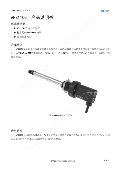
AFS1100 产品说明书风速传感器12~24V 直流工作电压 标准的Modbus-RTU 协议 超长使用寿命产品综述AFS1100是为测量气体流速而设计的传感器。
该传感器基于热膜式原理测量气体的流速。
产品使用了标准Modbus-RTU 数据输出信号格式。
每一个传感器的出厂都经过校准和严格的测试,满足客户的使用需求。
图1 AFS1100风速传感器应用范围AFS1100风速传感器对环境、气体及安装条件等的要求较为严苛,所以不适合在室外使用。
传感器主要应用于医疗及工业上通风管道内的风速测量。
慧传科技135377847慧传科技135377847081.传感器性能参数表1 传感器性能参数标定温度和气压 20℃,标准大气压 测量目标气体 空气、氮气(其它气体测量请咨询)测量范围 0~30m/s 检测下限 0.6m/s精度 量程小于10m/s 时,±(实际风速×3%+0.3m/s ) 量程大于等于10m/s 时,±(实际风速×5%+0.3m/s ) 重复性 ±(测定值×1.5%) 响应时间 1.5s (90%响应时间) 工作温度 -10℃~+45℃湿度范围 5~95%相对湿度 (RH),不结露 工作电压DC 12~24V 工作环境压力700~1300mbar2.产品尺寸图和零部件图2.1 AFS1100尺寸图图2 AFS1100尺寸图(单位:mm 标公差:±0.2mm )慧传科技135377847慧传科技135377847082.2 AFS1100零部件图1、传感器支撑外壳;2、金属管;3、金属针;4、 螺纹法兰;5、 法兰螺母;6、AFS1100上盖;7、扣线帽;8、Error 信号灯;9、Power 信号灯; 10、拨码开关;11、气流方向; 12、螺丝图3 AFS1100零部件示意图3.安装说明3.1 安装条件传感器在AFS1100上盖上标有箭头指示安装需要的气流方向,如图3中11所示。
欧门氏MAVT风速变送器,风速传感器说明书
● 输 出 有 过 压 及 反 接 保 护 措 施 ,高 可 靠 性 和抗干扰能力
● 多种输出方式可选,可选继电器输出实 现报警或控制
●现场跳线选择风速量程 0-5/10/15/20m/s
● 通过 MMI 可有多种参数设定、修改、校 正功能
可 选 MMI 操 作 面 板 :包 含 了 LCD,
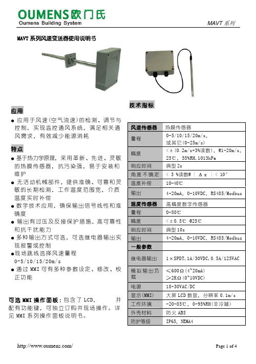
MAVT 系列风速变送器使用说明书
MAVT 系列
应用
● 应 用 于 风 速 (空 气 流 速 )的 检 测 、调 节 与 控制,实现监控通风系统,满足相关通 风需求,有效减少能源消耗
特点
● 基于热力学原理,采 用 革 新 、先 进 、灵 敏 的热膜传感器,抗污染强,易于安装和 维护
● 无 活 动 机 械部 件 ,提 供 准 确 、可 靠 和 灵 敏的长期检测,工作温度范围宽,介质 温度实时补偿
电源 显示(MMI) 工作环境 外壳材料 防护等级
≤600Ω(4~20mA) ≥2KΩ(0~10VDC) 18-30VAC/DC 大屏 LCD 数显,分辨率 0.1m/s -20-85℃,0-95%RH(非冷凝) 防火 ABS IP65,NEMA4
/
Page 1 of 4
/
Page 2 of 4
安装图(mm)
(参考安装说明)
前盖
图1
底盒
索头
探头应安装在较长直管段的中间 位置,建议前10D和后5D,且探头 应尽可能靠近风管截面中心。
AVT4
墙 螺丝
MAVT 系列
安装孔
103 60
底盒
螺丝
索头
探头/线缆
前盖
图2
图3
德州电子TV-114风速传感器用户手册说明书

Texas Electronics, Inc. Dallas, TX 75237 Fax.214.631.42184230 Shilling Way Tel.214-631-2490 TV-114TV-114-AWind Speed SensorUser’s Manual“Relied on Worldwide in the Most Extreme Conditions”Model TV-114 Wind Speed SensorDESCRIPTIONThe Texas Electronics, Inc. TV-114 Wind Speed Sensor is a mechanical style anemometer that measures the horizontal velocity of wind. The sensor is intended for long-term, maintenance-free operation.The TV-114 wind speed sensor is a freestanding device for measuring air velocity. The sensor consists of a lightweight 3-cup anemometer, which is mechanically coupled to an AC generator. As the cup mechanism rotates the AC generator produces an AC sine wave where the amplitude and frequency are proportional to wind speed.FEATURES & BENEFITS• Non-contacting, brushless AC generator for long-term maintenance free operation• No plastic parts for extremely long life• Precision stainless steel bearings for stability and repeatability• Crossarm included with purchase of matching wind direction sensor• Easy installation and maintenance• Over 25 years in production• Lightweight and rugged anodized aluminum exteriorINSTALLATION & MAINTENANCEInstallation consists of attaching the unit to a mast via the supplied mounting pole. If a crossarm is used, the entire unit can be bolted to a mast or attached via U-bolts.The sensor is dynamically calibrated at the factory and due to the nature of its operation should not require field calibration. Field maintenance should include occasional cleaning of the cup assembly and inspection of the internal mechanism to make sure it is free from insects and debris. In some applications, users may need to occasionally verify and document sensor accuracy with a synchronous test motor. Other possible routine maintenance involves replacing the bearing housing assembly every three to five years to maintain low starting threshold.ORDERING INFORMATIONModel # DescriptionTV-114 Wind Speed Sensor, Heavy IndustrialTV-114A Wind Speed Sensor, 4-20mA* Sensor is designed to work with TD-104-5D wind direction sensor.Optional Parts / AccessoriesT-8011M Synchronous motor for calibrationTV-114 WIND SENSORG-114 GENERATORThe chart below shows the maximum output obtainable from this generator, under a no load condition. This signal may be scaled down to fit many customer requirements.NOTES:l. Calibration may be checked by rotating the anemometer head at a known RPM. The above table shows the value that should be displayed on the indicator.2. The AC Volts column shows the output directly out of the transmitter.3. The DC Volts column shows the open circuit voltage out of the AC to DC adaptor.PROPER EXPOSURE OF METEOROLOGICAL INSTRUMENTSThe following generally recognized guidelines depict ideal sensor mounting locations. These guidelines are only suggestions to aid the user in selecting optimum representative sampling locations for a particular sensor. Reference was made to US Weather Bureau Installation criteria in preparing this data (See Reference 1).WIND EQUIPMENT:So far as available sites permit, wind sensors should be placed above the ground on a freely-exposed tower (20 feet or higher) and over terrain that is relatively level and free from obstructions to wind flow. When a compromise must be made, sensing units should be exposed at least 12 feet above any obstruction within 100 feet and at least as high as any obstruction within 100 to 200 feet of the wind equipment. Support towers or masts should not be of such bulk or shape as to create an appreciable obstruction to wind flow. Avoid sites where local obstructions may create up-or-down drafts, eddy currents or jet-flow effects. When sensors are roof-mounted, they should be installed at least 10 feet (or more) from the roof surface, depending upon the particular installation site. Turbulence and other local effects can be reduced somewhat by mounting sensors on the upwind end of the building (the end of the building exposed to the most common local prevailing winds). Horizontal-mount booms that extend from existing towers should be fabricated so that sensors will extend a distance of 5 to 10 feet from the tower assembly (dependent on tower thickness).Wind direction sensors are oriented upon installation in reference to either true north or magnetic north. True north is obtained by applying a local magnetic variation correction factor to a magnetic north compass indication (magnetic variation for a particular locality is obtainable from the nearest Weather Bureau Branch Office). Indicator readings for a true north sensor orientation will then be in terms of true geographic compass points. All U.S. Weather Bureau surface wind data used for observational network reporting purposes and general public use is given in reference to this true north format. Indicator readings for a magnetic north sensor orientation will be in terms of actual readings as would be obtained from directly viewing a magnetic compass instrument. Wind direction data at Federal Aviation Agency and other aircraft reporting facilities (for direct control tower-to-pilot utilization) is always made in reference to this magnetic north format.WarrantyTexas Electronics, Inc. (hereafter TEI) warrants the equipment manufactured by it to be free from defects in material and workmanship. Upon return, transportation charges prepaid to TEI, within three (3) years of original shipment of sensors and one (1) year of original shipment of electronics, recorders and indicators, TEI will repair or replace, at its option, any equipment which it determines to contain defective material or workmanship, and will return said equipment to purchaser, F.O.B., TEI. Texas Electronics shall not be obligated however to repair or replace equipment which has been repaired by others, abused, improperly installed, altered or otherwise misused or damaged in any way. TEI will not be responsible for any dismantling, re-assembly, or reinstallation charges.This warranty is in lieu of all other warranties, expressed or implied. TEI shall not be liable for any special, indirect, incidental or consequential damages claimed in connection with any rescission of this agreement by purchaser.。
南华机电 FA121 风速传感器 说明书

FA121传感器测量原理示意图传感器接线图接头 图1图2图3图4附:风级、风速、风压对照表 (机构与结构设计参考)风级 名称 风速 风压陆地地面物体征象 海面状态 km/h m/s W0=V2/16(kg/m²),10N/m²0 无风 <1 0~0.2 0~0.0025 静 静1 软风 1~5 0.3~1.5 0.0056~0.014 烟能表示方向,但风标不动微波2 轻风 6~11 1.6~3.3 0.016~0.68 人面感觉有风,风向标转动小波3 微风 12~19 3.4~5.4 0.72~1.82 树叶及微枝摇动不息,旌旗展开小波4 和风 20~28 5.5~7.9 1.89~3.9 能吹起地面纸张与灰尘 轻浪5 清风 29~38 8.0~10.7 4~7.16 有叶的小树摇摆 中浪6 强风 39~49 10.8~13.8 7.29~11.9 小树枝摇动,电线呼呼响 大浪7 嫉风 50~61 13.9~17.1 12.08~18.28 全树摇动,迎风步行不便 巨浪8 大风 62~74 17.2~20.7 18.49~26.78 微枝折毁,人向前行阻力甚大狂浪9 烈风 75~88 20.8~24.4 27.04~37.21 建筑物有小损 狂涛10 狂风 89~102 24.5~28.4 37.52~50.41 可拔起树来,损坏建筑物 狂涛11 暴风 103~117 28.5~32.6 50.77~66.42 陆上少见,有则必有广泛破坏狂涛12 飓风 >117 32.7~36.9 66.42~85.1 陆上极少见,摧毁力极大 海浪涛天13 37.0~41.414 41.5~46.115 46.2~50.916 51.0~56.017 56.1~61.2。
SD3788B 显示型热式管道型风速传感器产品使用手册说明书

SD3788B显示型热式管道型风速传感器产品使用手册文件版本: V23.6.20SD3788B采用工业通用标准接口,方便接入PLC,DCS等各种仪表或系统,用于监测热式风速等状态量。
内部使用了较高精度的传感内核及相关器件,确保产品具有较高的可靠性与卓越的长期稳定性, 可定制RS232、RS485、CAN、4-20mA、DC0~5V\10V、ZIGBEE、Lora、WIFI、GPRS、NB-IOT等多种输出方式。
技术参数产品设计了RS485,4-20mA,DC0-5V,DC0-10V多种输出方式,根据输出方式的不同,产品分外形尺寸请在断电线的情况下,按图示方法进行接线,如果产品本身无引线,线芯颜色供参考。
典型应用应用方案发货清单RS485型:通讯协议产品使用RS485 MODBUS-RTU标准协议格式,所有操作或回复命令都为16进制数据。
设备出厂时默认设备地址为1,默认波特率为模块及非记录仪表:9600,8,n,1 或记录仪:115200,8,n,1 。
1. 读取数据( 功能码0x03)问询帧(十六进制),发送举例:查询1#设备1个数据,上位机发送命令:01 03 00 00 00倍率为100,则真实值为121/100=1.21,其它以此类推。
2. 常用数据地址表3 读取与修改设备地址(1)读取或查询设备地址若不知道当前设备地址、且总线上只有一个设备时,可以通过命令FA 03 00 66 00 01 71为设备地址的寄存器。
对于正确的查询命令,设备会响应,比如响应数据为:01 03 02 00 01 79 84,其格式解(2)更改设备地址效,此时用户需要同时将自己软件的查询命令做相应更改。
4 读取与修改波特率(1)读取波特率设备默认出厂波特率为9600,若需要更改,可根据下表及相应通讯协议进行更改操作。
比如读取当前设备的波特率ID,命令为:01 03 00 67 00 01 35 D5 ,其格式解析如下。
风速仪使用说明书
风速仪使用说明书
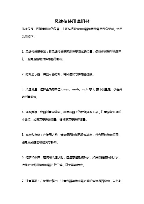
风速仪是一种测量风速的仪器,主要包括风速传感器和显示器两部分组成。
使用说明如下:
1. 风速传感器安装:将风速传感器固定在要测试的位置,保持传感器与地面平行,避免遮挡物对传感器的影响。
2. 打开显示器:将显示器打开,将风速仪与传感器连接。
3. 风速测量:选择正确的单位(m/s、km/h、mph等),按下测量键,仪器开始测量风速。
4. 读取数据:仪器测量完毕后,将显示器上的数据读取下来,注意保留正确的小数位。
如果需要连续测量,请根据需要进行设置。
5. 充电和存储:在使用之前,请确保风速仪已经充满电,并合理地储存仪器,避免受到撞击或湿润等影响。
6. 维护和保养:在使用风速仪时,应注意避免接触水,如果仪器接触到了水,请及时拆卸风速传感器进行干燥,以免影响精度。
7. 注意事项:在使用过程中,注意仪器与传感器之间的连接是否松动,以免影
响测量精度。
此外,还要避免仪器接触到强电磁场、辐射场等,以减少干扰。
FST200-205A 加热型风速风向一体传感器 产品说明书
加热型风速风向一体传感器产品说明书(V1.1)湖南菲尔斯特传感器有限公司Hunan Firstrate Sensor Co.,Ltd●重要声明非常感谢您购买菲尔斯特产品,我们为您真诚服务到永远。
菲尔斯特追求卓越的品质,更注重优良的售后服务,如有需要请拔打:400-607-8500(7×24h)。
操作错误会缩短产品的寿命,降低其性能,严重时可能引起意外事故。
请您将本说明书交到最终用户手中,在产品使用前务必仔细熟读。
并请妥善保管好,以备需要时查阅。
本说明书仅供参考所用,具体产品外形以实物为准。
●产品概述本风速风向一体传感器用于测量风速及风的方向值,并转换为电信号,此信号可直传送到记录设备上进行处理。
传感器壳体采用铝合金材料,使用特种模具精密压铸工艺,尺寸公差甚小表面精度甚高,同时具用高耐候性、高强度、防腐蚀和防水性;内部电路均经过防护处理,整个传感器具有很好的耐恶劣环境的适应性。
电缆接插件为军工插头,具有良好的防腐、防侵蚀性能,能够保证仪器长期使用,同时配合内部进口轴承系统,确保了风速及风向采集的精确性。
电路模块PCB采用军工级A级材料,确保了参数的稳定和电气性能的品质;电子元件均采用进口工业级芯片,使得整体具有极可靠的抗电磁干扰能力,能保证主机在-20℃~+85℃范围内均能正常工作。
●功能特点1、体积小,携带方便、安装简捷、外观精美;2、有较强的防腐蚀性和耐候性;3、测量精度高,量程范围宽,稳定性好;4、功耗低,较强的抗干扰能力,能长期稳定工作;5、电源适应范围宽,数据信息线性度好,信号传输距离长。
●适用范围本品可测量室内外环境中东、西、南、北、东南、西南、东北,西北等十六个方向,可广泛用于工程机械(起重机、履带吊、门吊、塔吊等)领域,铁路、港口、码头、电厂、气象、索道、环境、温室、养殖、空气调节、节能监控、农业、医疗、洁净空间等领域的风速及风向测量。
●技术参数数字型RS485(Modbus RTU)电源DC10~30V量程风速:0-50m/s风向:16个方向(0-360度)精度风速:±0.5m/s(<5m/s);±3%FS(≥5m/s)风向:±3度分辨率22.5°最大功耗(DC24V)RS485型MAX≤300mW启动风力≥1级风加热功率60W工作温度-20~85℃防护等级IP65如有特殊规格要求请另行告知●结构尺寸注意:安装时箭头方向指北,出线请参考上图向法兰盘弯折,避免影响风向标转动。
Flow Sensor Series 641RM 风速传感器的安装和操作说明说明书
Series 641RM Air Velocity TransmitterSpecifications - Installation and Operating InstructionsBulletin E-66-RMThe Series 641RM Air Velocity Transmitter uses a heated mass flow sensortechnology. It has 8 user selectable ranges from 250 FPM to 15000 FPM withcorresponding metric ranges of 1.25 MPS to 75 MPS. The Series 641RM Air VelocityTransmitter provides an isolated 4-20 mA out-put proportional to the velocity. With theoptional 1/2˝ 4-1/2 digit LED display, the Series 641RM Air Velocity Transmitter willprovide a highly visible local readout of the velocity.INSTALLATIONLocation: Select a location where the temperature will be within 32 to 140°F (0 to60°C) to mount the enclosure. The transmitter may be located any distance from thereceiver provided that the total loop resistance does not exceed 600 Ω. The probeshould be located where conditions are representative of the overall environmentbeing monitored. Avoid locations where turbulence, stagnation, or rapidly fluctuatingvelocities or temperatures are present as these conditions may affect the readings.The filter setting may be used to average velocity readings in turbulent conditions.Position: The transmitter is not position sensitive and may be mounted in anyorientation.Probe Orientation: Dots on the probe indicate the direc-tion of the calibrated airflow.Align these dots toward the source of the process air.Airflow: The Series 641RM Air Velocity Transmitter is intended for use with clean dryair. Particulates in the air may cause sensor damage. Dust accumulation may impairthe velocity measurement and will require probe cleaning.TO READ DISPLAY UNIT MUST BE MOUNTED HORIZONTALLY AS SHOWNABOVE. DISPLAY CAN BE TURNED 180 SO CONDUIT OPENING CAN BEPOSITIONED TO THE RIGHT OR LEFT.Note: Where conduit connections are not made, a 1/2˝ NPT cable seal should be used to prevent contaminants from entering the case. Where conduit connections are made, make sure that any possible condensation within the conduit will not flow into the transmitter housing.ELECTRICAL CONNECTIONThe Series 641RM Air Velocity Transmitter has been designed for easy and flexible connection to power and loop receivers. Electrical connection is made inside thebody of the device with a “Euro” style terminal block. The device features a current loop that is fully isolated from the power source. The current loop has an internal 24 V isolated supply so no external loop power is required. With full isolation, loop grounding is not a concern. The input power requirements are also very flexible. The device may be powered from either an AC or DC power source.Receiver-Transmitter Connection — The Series 641RM Air Velocity Transmitter is designed as a three or four wire 4-20 mA device. The current loop output is isolated from the power supply input and provides an internal 24-volt loop supply. With a DC power supply, a three or four-wire connection may be used. Do not use a three-wire connection with an AC power source. In a three-wire connection either power supply wire may be used as the common. The total loop resistance should not exceed 600 Ω.Power Supply Connection — The power supply may be either AC or DC. The DC power may be from 12-35 V. The power connection is not polarity sensitive so the positive and negative connections may be made to either power terminal. The AC connection may be from 10-16 VAC RMS. Do not exceed 20 VAC. When selecting a transformer please note that the specified output for transformers is at some specified current. With a load current less than the specified current transformer output may be significantly higher than the specified voltage. Transformers with secondary voltages of 10-16 VAC are recommended.Do not exceed the specified supply voltage rating. Permanent damage not covered by the warranty may result. Do not use anexternal power source on the current loop connection.Do not use a receiver with an internal power supply or use an external supply in the current loop. The current loop is poweredfrom within the Series 641RM Air Velocity Transmitter. Connecting an external supply to the current loop may destroy the transmitter. Using an external supply voids thewarranty.Do not use transformers with a secondary voltage rating greaterthan 16 VAC RMS.Interior label diagramPOWER SUPPLY AC OR DC RECEIVER4-WIRE 3-WIRERECEIVER NEGATIVECOMMONRECEIVERDC SUPPLY ONLY (EITHER POLARITY)3-WIRERECEIVER POSITIVECOMMONRECEIVERDC SUPPLY ONLY (EITHER POLARITY)3 or 4-wire connectionWire Type and Length — The wire selection for an installation is often overlooked or neglected and may contribute to improper or even intermittent operation. In all cases ensure that the connection meets all applicable national and local electrical codes. Although the 4-20 mA current loop systems are relatively immune to wire or wiring related problems, selection of the wire for some installations will be an important factor in ensuring satisfactory system operation. Twisted conductors will usually be immune to most stray electric and magnetic fields and to some extent electromagnetic fields, such as interference from RF transmitters. With twisted pair wiring the current loop and the power connections should be separate pairs. Avoid using flat or ribbon cable that has no regular conductor twist. Where interference is possible, it is recommended that shielded wire be used. The shield must not be used as one of the conductors and should be connected to ground at only one end, generally at the power supply. Similarly, if the installation uses conduit, the conduit should be connected to protective ground as specified by the applicable code and the signal wiring must not be connected to the conduit at more than one point or as specified by the code. The maximum length of wire connecting the transmitter and receiver is a function of the wire resistance and receiver resistance. The total loop resistance must not exceed 600 Ω, including the receiver resistance and wire resistance. The power supply connection must be designed so that the worst case voltage drop due to wire resistance will not cause the power supply voltage at the transmitter to drop below the specified value. Provided the power supply voltage is maintained within the specified voltage range, the Series 641RM Air Velocity Transmitter is not affected by variations in power supply voltage.TRANSMITTER SETUPThe Series 641RM Air Velocity Transmitter has been designed for easy setup. It has five configuration parameters that may be adjusted by the user. These parameters are Output Filter, Range (in English or Metric), span, 4 mA set-point and 20 mA set-point. All of these may be adjusted at any time in the field. These adjustments may also be easily returned to factory default.A set of controls and indicators are provided within the unit consisting of the select button, enter button, adjustment control, and six LED indicators. When operating normally, only the RUN LED indicator will be illuminated. During the setup operation the LED indicators will indicate the parameter selected, when it is being adjusted, and status of the adjustment process. If the unit is left in the setup mode for several minutes without any activity it will return to the normal operating mode.Two buttons and a potentiometer control the setup process.The SELECT button is used to scroll between the setup parameters. The ENTER button allows access to each parameter for adjustment.The ADJUST potentiometer is used to change the value of the parameters. Holding the ENTER button for 2.5 seconds saves the new parameter value.Making AdjustmentsThe adjustment process has three steps: select the para-meter, adjust the parameter, save the new value. These are described in the following steps.1. Select the parameter: Each time the SELECT but-ton is pressed the LED indicator will advance to the next parameter. When the last parameter, SPAN, is selected, the next time the SELECT is pressed the unit will return to RUN mode. Pressthe SELECT button until the LED indicator illuminates the desired parameter. Press ENTER. The selected indicator will begin to blink, show-ing the parameter may now be adjusted. If the unit is left in the setup mode, after several minutes it will reset to the operate mode.2. Adjust the parameter: Turn the ADJUST poten-tiometer until the desired setting is made. This may be adjusted using a small screwdriver or similar tool. Be careful not to force the control past its stops or damage will result.3. Save the parameter: To save the new parameter press and hold the ENTERbutton. The LED indicator will begin to flash at a faster rate. After about 2.5 seconds all of the LED indicators will flash when the parameter is saved. If you do not want to save the parameter press the SELECT button without entering the parameter.The adjusted value will be discarded and next LED indicator will be illuminated.Adjusting the Output FilterThe output filter may be adjusted to smooth the readings when measuring turbulent flow. The time constant may be adjusted from 0.5 seconds to 15 seconds. To adjust the fil-ter time constant, select the FILTER indicator. Press ENTER to enable adjustment. Turn the ADJUST until the desired amount of damping is achieved. To save the value press and hold the ENTER button until the LED indicators all flash, indi-cating the value was saved. To discard the adjustment press SELECT before pressing the ENTER button.1: Indicator on0: Indicator offRange SelectionThe range selection allows you to select one of eight ranges in either feet per minute (FPM) or meters per second (MPS).Ranges:FPM: 250, 500, 1000, 2000, 3000, 5000, 10000, 15000 MPS: 1.25, 2.5, 5, 10, 15, 25, 50, 75Select the RANGE indicator by pressing ENTER when the RANGE LED indicator is illuminated. The A,B,C LED indi-cators will display which range setting is currently active. Press ENTER to enable adjustment. Turn the ADJUST until the desired range indication is achieved. If you want to dis-card the adjustment press SELECT. If you want to save the range press and hold ENTER. The RANGE LED will blink at a faster rate for about 2.5 seconds then all of the LEDs will flash indicating the value was saved.The range setting is displayed with the LED indicators. The function of these indicators is summarized on the control label inside the unit. The following table summarizes the indicator status for each range settingPrinted in U.S.A. 7/21FR# 443309-00 Rev. 2©Copyright 2021 Dwyer Instruments, Inc.Span SettingThe Series 641RM Air Velocity Transmitter has been cali-brated for standard sea level conditions. As a mass flow device it will always read the air velocity for standard condi-tions. Density changes due to barometric or absolute pres-sure are not corrected automatically. The span setting allows correction for altitude or other static pressure condi-tions that affect the density of the process air. This parame-ter allows for a ±50% adjustment in the span value.To make the span adjustment you will need to know either the absolute static pressure or the corrected velocity of the process air. Set the air velocity to a known value, ideally about 3/4 of the full-scale range value. Press SELECT until the SPAN LED indicator is illuminated then press ENTER. The SPAN LED will begin to blink. Adjust the control for the desired velocity then press and hold the ENTER button until all of the LED’s flash, indicating the new value was saved. If you know the absolute static pressure you can compute the corrected velocity using the following equation:Where:P0 is the standard pressure of 29.9 in. Hg. or 760 mm Hg PA is the absolute pressure readingVrdg is the indicated velocity Vcor is the corrected velocity4 mA SettingTo make this setting you will need a milliammeter connect-ed in the current loop. It is not required to use a known air flow velocity to make this calibration setting. The calibration settings of the velocity and mA outputs are independent of each other. Press SELECT until the 4 mA LED indicator is illuminated then press ENTER. The milliammeter will now read approximately 4.0 mA. Adjust the control for a 4.0 mA reading on the milliammeter. Press and hold ENTER to save the new setting. Pressing SELECT before pressing ENTER will restore the previous calibration value.20 mA SettingIt is not required to use a known air flow velocity to make this calibration setting. The calibration settings of the veloc-ity and mA outputs are independent of each other. With the milliammeter connected in the current loop, press SELECT until the 20 mA LED indicator is illuminated. Press ENTER to begin adjustment of the 20 mA set point. The 20 mA LED will now be blinking. Adjust the control until the milliamme-ter reads 20.0 mA. Press and hold ENTER to save the new setting. Pressing SELECT before pressing ENTER will restore the previous calibration value.Restoring Factory Default SettingsThe 4 mA, 20 mA, and Range settings override factory default values. To restore these to the factory default set-tings, start with the unit in the RUN mode. Press and hold the ENTER button. The RUN LED indicator will begin to blink. After about 2.5 seconds all LED indicators will flash indicating the factory settings have been restored. Range and Filter settings are not affected by this operation. If you are unsure whether any have been altered, press the SELECT button six times to sequence through all settings. When you return to the RUN mode, the RUN LED indicator will blink several times if either the 4 mA, 20 mA, or span settings have been changed. The RUN LED will otherwise remain on.MAINTENANCEIn general the Series 641RM Air Velocity Transmitter should require very little maintenance. In some installations dust may accumulate on the sensor over time. This can be removed by carefully brushing the probe with a small camel hairbrush. If too much force is applied during cleaning, the sensor of the Series 641RM Air Velocity Transmitter may be damaged. Therefore, a trained technician should perform the cleaning operation. A jet of air may also dislodge the accumulated buildup. However, the sensor is delicate and this operation should be done carefully with clean regulated air. Using a shop air supply may exert enough force to dam-age the sensor. Most air supplies of this sort will also con-tain water or oil that could damage the sensor. Technical grade denatured or isopropyl alcohol may be used where the dust accumulation does not respond to brushing. Do not use water. Always disconnect the power when perform-ing a cleaning operation.Aside from field calibrations for span, 4 mA and 20 mA set-ting as described above, the Series 641RM Air Velocity Transmitter cannot be fully factory calibrated in the field. Because of specialized computer instrumentation required, these units must be returned to Dwyer Instruments for fac-tory calibration. Contact customer service to receive a return goods authorization number before shipping.V cor = V rdgP OP A。
PHWS系列风速传感器使用说明书
产品介绍PHWS风速传感器(变送器)采取传统三风杯风速传感器结构, 风杯选择碳纤维材料, 强度高, 开启好; 杯体内置信号处理单元能依据用户需求输出对应风速信号, 可广泛用于气象、海洋、环境、机场、港口、试验室、工农业及交通等领域。
技术参数测量范围: □ 0~45m/s□ 0~70m/s准确度: ±(0.3+0.03V)m/s(V:风速)分辨率: 0.1m/s开启风速: ≤0.3m/s供电方法: □DC 5V□DC 12V□DC 24V□其她输出形式: □脉冲: 脉冲信号□电流: 4~20mA□电压: 0~5V□电压: 0~2.5V□RS232□RS485□TTL信号□其她负载能力: 电流型输出阻抗≤600Ω电压型输出阻抗≥1KΩ工作环境: 温度-40℃~50℃湿度≤100%RH防护等级: IP45线缆等级: 额定电压: 300V 温度等级: 80℃产品重量: 130 g产品功耗: 50 mW计算公式脉冲型:W =0; (f = 0)W =0.3+0.0877×f(f≠ 0)(W: 风速示值(m/s); f: 脉冲信号频率)电流型(4~20mA):W = (i-4)×45/16(W: 风速示值(m/s); i: 电流信号(4-20mA))电压型(0~5V):W =V/5×45(W: 风速示值(m/s); V: 电压信号(4-20mA))接线方法传感器底部有一个5芯航空插头, 其针脚对应管脚定义如图所表示。
(1)若配置本企业生产气象站, 直接使用传感器线将传感器与气象站上对应接口相连即可。
(2)若单独购置变送器, 变送器配套线线序分别为:红色: 电源+黄色: 输出信号绿色: 电源—(3)脉冲电压、电流两种输出接线方法:(电压、脉冲方法接线)(电流输出方法接线)结构尺寸风速传感器底座安装尺寸图:安装孔径: 4mm分布直径: 62.5mm航插直径: 15mm(提议预留25mm便于布线)注意事项1、请检验包装是否完好, 并查对产品型号是否与选型一致;2、切勿带电接线, 接线完成检验无误后方可通电;3、使用时不要随意改动产品出厂时已焊接好元器件或导线;4、传感器属于精密器件, 用户在使用时请不要自行拆卸、用尖锐物品或腐蚀性液体接触传感器表面, 以免损坏产品;5、请保留好检定证书和合格证, 维修时随同产品一同返回。
测试科技 010C 风速传感器和 020C 风向传感器产品说明书
The 010C Wind Speed Sensor provides accurate and detailed information on horizontal wind speed. The lightweight three-cup anemometer is used in virtually all applications where fast response and low starting threshold(s) are of paramount importance.The 020C Wind Direction Sensor provides azimuth data for use in micrometeorological measurements related to operational studies and research. The lightweight airfoil vane is directly coupled to a single precision potentiometer. These sensors are especially useful when a low starting threshold, a high damping ratio, or a short delay distance is required.Both wind speed and wind direction sensors are used inenvironments ranging from Antarctic cold to arid desert heat. The 01OC, 010C-1, and 020C instruments meet U.S. EPA and NRC performance specifications for critical regulatory, research or scientific measurement applications.ReliabilityThe 010C and 020C are made of stainless steel and anodized aluminum components and are functionally more reliable than any other sensors of their kind:• Built-in electrical field surge protection greatly reduces problems associated with static fields, near-miss lightning hits and poor grounding systems• Inclusion of Met One Instruments’ internal heater (AC use only) provides positive clean aspiration through the bearings, thereby greatly increasing sensor bearing life• Optional, external de-icing heater sleeve for applicationswhere freezing rain, ice and low wind speeds may be encounteredFeatures• Low starting threshold• Internal heater for long bearing life• Low profile to minimize “sensor turbulence”• High damping ratio • Short delay distance• Quick-disconnect connector• Field-replaceable electronic components • Ingress Protection Level 65 (IP65)010C Wind Speed Sensor020C Wind Direction SensorCable Assembly; specify length in feet or meters PN 191 Crossarm AssemblyCable Assembly; specify length in feet or meters PN 191 Crossarm Assembly15 ft. (4.6 m) aluminum cup assembly (meets EPA specifications) 0.25 (aluminum tail)Cable & MountingPN 1953Mounting:Cable & MountingPN 1957Mounting:Alternate Wind Sensors010C-1Distance Constant: 020C-1Damping Ratio:Specifications are subject to change at any time.020C Wind Directon Sensor Specifications0-135mph (0-60m/s)0.5 mph (0.22 m/s) 0 -l/0 mph (0 -50 m/s)±1% or 0.15 mph (0.07 m/s) Resolution <0.1 mph or m/s-50°C to +65°C (-58°F to +149°F)less than 5 It (1.5m) of flow (meets EPA specifications)Electrical 0° -357° Mechanical 0° -360° 0.5 mph (0.22 m/s) ±1/2% of full scale ±3°Resolution <0.1 °Standard 0.6 (magnesium tail) (meets EPA specifications) Less than 3 It (91 cm)-50°C to +65°C (-58°F to +149°F1.5 Ibs (.68 kg)Clear anodized aluminum; Lexan cup assembly1.5 Ibs (.68 kg)Clear anodized aluminum12 VDC at 10 mA, 12 VDC at 350 mA for internal heater 11 volt (pulse frequency equivalent to speed) 100 Ω maximum12 VDC at 10 mA, 12 VDC at 350 mA for internal heater a. 0 -5 V for 0° -360° b. 0 -2.5 V for 0° -360° 100 Ω maximum Performance CharacteristicsMaximum Operating Range: Starting Speed: Calibrated Range: Accuracy:Temperature Range: Distance Constant:Performance CharacteristicsAzimuth:Threshold: Linearity: Accuracy:Damping Ratio: Delay Distance: Temperature Range:Physical CharacteristicsWeight: Finish:Physical CharacteristicsWeight: Finish:Electrical CharacteristicsPower Requirements: Output Signal:Output Impedance:Electrical CharacteristicsPower ReqUirements: Output Signal: Output Impedance:010C Wind Speed Sensor REV JULY 20181600 Washington Blvd. • Grants Pass, Oregon 97526 • 541.471.7111 • Technical Drawings020C Wind Direction Sensor191-1 Mounting Arm & 010C-020C010C Wind Speed SensorREV MAR. 20181.05 (27 mm) DSHOWN WITH 5315 ICE SKIRT (Optional)MS CONNECTOR1553 MOUNTING ADAPTER 1686 ALIGNMENT ADAPTER1552 MOUNTING ADAPTERDIAMETER TO FIT3/4” IPS PIPE1552 MOUNTINGADAPTER3/4” IPS PIPE 1” DIAMETER191-1 CROSS ARM ASSEMBLYCABLE 19571.05 (27 mm)SHOWN WITH 5315 ICE SKIRT (Optional)CABLE 1953DIAMETER8.00” (203 mm)60.00” (1524 mm)16.92” (430 m m )16.92” (430 m m )C LC L。
- 1、下载文档前请自行甄别文档内容的完整性,平台不提供额外的编辑、内容补充、找答案等附加服务。
- 2、"仅部分预览"的文档,不可在线预览部分如存在完整性等问题,可反馈申请退款(可完整预览的文档不适用该条件!)。
- 3、如文档侵犯您的权益,请联系客服反馈,我们会尽快为您处理(人工客服工作时间:9:00-18:30)。
目 录 一、产品概述 .............................................. 二、应用范围 .............................................. 三、技术参数 .............................................. 四、功能特点 .............................................. 五、结构尺寸图 ............................................ 六、固定方式 .............................................. 七、信号输出定义 .......................................... 八、线色定义 .............................................. 九、脉冲型风速输出电路图 .................................. 十、脉冲输出型计算 ........................................ 十一、RS485/232通讯协议 .................................. 十二、风力等级划分表 ...................................... 十三、风速与输出信号对应表 ................................ 一、产品概述 该三杯式风速传感器是我公司自主研发、生产的一款风速测量仪器,本品由壳体、风杯和电路模块组成,内部集成光电转换机构、工业微电脑处理器、标准电流发生器、电流驱动器等。 传感器壳体和风杯采用铝合金材料,使用特种模具精密压铸工艺,尺寸公差甚小表面精度甚高,内部电路均经过防护处理,整个传感器具有很高的强度、耐候性、防腐蚀和防水性。电缆接插件为军工插头,具有良好的防腐、防侵蚀性能,能够保证仪器长期使用,同时配合使用风速传感器内部进口轴承系统说明书,确保了风速采集的精确性。 电路PCB采用军工级A级材料,确保了参数的稳定和电气性能的品质;电子元件均采用进口工业级芯片,使得整体具有极可靠的抗电磁干扰能力,能保证主机在-20℃~+50℃,湿度35%~85%(不结露)范围内均能正常工作。
二、应用范围 本产品可广泛运用于工程机械(起重机、履带吊、门吊、塔吊等)领域,铁路、港口、码头、电厂、气象、索道、环境、温室、养殖、空气调节、节能监控、农业、医疗、洁净空间等领域风速的测量,并输出相应的信号。 三、技术参数 □脉冲输出型:□ NPN输出 □ PNP输出 □ NPN输出带内部上拉(Ω) □RS485通讯型 □电压输出型:□ 0-2VDC □ 0-5VDC □ 0-10VDC □电流输出型: 4-20mA 电源:根据输出类型不同所需的电压源范围不同 电流输出型: 12~24V 电压输出型:输出0-2VDC:6~24V 输出0-5VDC:6~24V 输出0-10VDC:12~24V 脉冲输出型:5~24V 量程:□0-30m/s □0-60m/s 负载能力: □其他 □<500Ω □>2kΩ 最大功耗(DC24V): 脉冲型MAX≤200mW; 电压型MAX≤300mW; 电流型MAX≤700mW; 启动风力:~s 重量:≤
四、功能特点 该产品自投入市场以来,以其优异的质量,卓越的性能赢得广大用户的好评,具备以下特点: ◆ 外观结构设计合理、美观大方,体积小,便于携带,安装简便。 ◆ 测量精度高,量程范围宽,稳定性好。 ◆ 有较强的防腐蚀性和耐候性。 ◆ 动态特性好,抗外界干扰能力强,测量精度高。 ◆ 功耗低,电路寿命长,能长期稳定工作; ◆ 电源适应范围宽,数据信息线性度好,信号传输距离长。
五、结构尺寸图 六、固定方式 传感器应水平安装,确保风向数据的准确性;采用法兰安装方式, 传感器下方安装法兰直径Ф60mm,四个安装孔为Ф,四个安装孔均匀分布再Ф47mm的圆周上,安装使用法兰固定安装,安装尺寸如下:
七、信号输出定义 电压型和电流型输出定义如下 RS485输出定义
八、线色定义 线 型 常用颜色 备用颜色 电源线色 红色 地线线色 黑色 信号线色 蓝色--------A+ 黄色---------B-
九、脉冲型风速输出电路图 PNP输出电路图如下:(最大输出电流Icmax=100mA) 当用电压信号时, 需要连接电阻RL NPN输出电路图如下:(最大灌电流Icmax=20mA) 当用电压信号时, 需要连接电阻RL 内部带上拉电阻NPN输出电路图如下:(R=Ω)
十、脉冲输出型计算 风速=单位时间内的脉冲数X系数; 公式中:单位时间内指的是1S; 型号尾缀为4CM,则系数为 型号尾缀为8CM,则系数为 型号尾缀为12CM,则系数为 型号尾缀为16CM,则系数为
十一、RS485/232通讯协议 采用了MODBUS-RTU协议的命令子集,使用读寄存器命令(03)(06)。 1、数据传输方式: 8位数据位,1位停止位,无校验位。
2、数据传输速率: 缺省波特率为9600bps,不可修改,用户希望使用其他波特率时,请在定货时声明。支持波特率:9600bps,4800bps,2400bps,1200bps。 3、数据报文格式 ⑴功能码0x03---查询从设备寄存器内容
主设备报文 从设备正确报文 从设备地址 (0x01-0xFE 1字节) 从设备地址 (0x01-0xFE 1字节) 功能码 (0x03 1字节) 功能码 (0x03 1字节) 起始寄存器地址 (2字节) 数据区字节数 (2*寄存器个数1字节) 寄存器个数 (2字数据区 (寄存器内容2*寄存器⑵功能码0x06---对从设备寄存器置数 注:1、CRC检验码低位在前、高位在后,寄存器地址, 寄存器个数,数据均为高位在前、低位在后; 2、寄存器字长为16bit(两个字节); 4、寄存器说明与命令格式 (1)参量数据寄存器定义表 寄存器地址(Hex) 寄存器内容 寄存器个数 寄存器状态 数据范围(Hex)
节) 个数1字节) CRC校验码 (2字节) CRC校验码 (2字节)
主设备报文 从设备正确报文 从设备地址 (0x01-0xFE 1字节) 从设备地址 (0x01-0xFE 1字节)
功能码 (0x06 1字节) 功能码 (0x06 1字节) 起始寄存器地址 (2字节) 数据区字节数 (2*寄存器个数1字节) 写入寄存器的数据 (2* 寄存器个数1字节) 数据区 (寄存器 内容 2* 寄存器个数1字节) CRC校验码 (2字节) CRC校验码 (2字节) 0x002A 风速 1 只读 0~3000(0x00-0x0BB8) 提示:自2013年12月20日起所有485风速传感器风速值寄存器地址全部修改为0x002A,老客户使用过的风速值寄存器地址0x0010、0x0002、0x0000,修改后的协议仍然支持上述地址,客户无需做修改。 数据范围0x0000-0x0BB8代表米/秒风速。 寄存器地址(Hex) 寄存器内容 寄存器个数 寄存器状态 数据范围(Hex)
0x4000 设备地址 1 读写 1~254(0x01~0xFE) (2)命令举例: 命令中所有寄存器地址字节、寄存器个数字节、数据字节高位在前,低位在后;CRC校验码低位字节在前,高位字节在后; 读取风速值: (从设备地址02号,波特率为9600,N,8,1)
从设备地址 功能码 起始寄存器地址 寄存器个数 CRC-L CRC-H 0x02 0x03 0x00 0x2A 0x00 0x01 0XA5 0xF1 从设备回应:
从设备地址 功能码 数据区字节数 寄存器数据 CRC-L CRC-H 0x02 0x03 0x02 0x00 0x00 0xFC 0x44 修改设备地址: (从设备地址02号,修改为03号)
从设备地址 功能码 起始寄存器地址 修改后数据 CRC-L CRC-H 0x02 0x06 0x40 0x00 0x00 0x03 0XDC 0x38 从设备回应:
从设备地址 功能码 起始寄存器地址 修改后数据 CRC-L CRC-H 0x03 0x06 0x40 0x00 0x00 0x03 0XDD 0xE9 十二、风力等级划分表 十三、风速与输出信号对应表 风速(m/s) 电流输出4-20mA 电压输出(0-5V) 电压输出(1-5V) 电压输出(0-2V)
1 2 3 4 5 6 1 7 8 9 10 11 12 2 13 14 15 12 3 1 16 17 18 3 19 20 21 22 23 24 4 25 26 27 28 29 30 20 5 5 2 十四、维护和保养