505简易操作说明书
505系统的的操作

505系统的的操作一.开机操作:1.机组应满足所有的启动条件2.将1个速关阀打开后,方可到“505控制系统”进行开机操作。
3.按“Clear”键(清屏)和“Reset”键(复位),进入“Push Run/program”状态下,按“Run”键(运行)开始冲转,转速自动升至600r/min。
4.暖机结束后开始升速。
如果画面中只有一运行转速时,按方向键中的向下键,就可以看到二运行转速(“@speed”为实际转速,“setpt”为设定转速)。
5.如果再其他界面里,按数字键“7”进入转速画面。
6.在转速画面中进行升速:首先按“ENTER”键(确认)进入“new speed(设定新转速):”界面,提示输入新的转速;再用数字键输入新的转速后,再次按“ENTER”键,确认两运行转速都在上升。
7.如果再输入转速时设定错误,可以按“Clear”键消除,然后重复上面操作重新设定新的转速。
二.停机操作:在降速停机前先将机组负荷降至最低进入505操作盘的转速画面中,按下“Stop”键,再按确认键“1/yes”,确认汽轮机转速下降,调节气门开始关闭。
等到505设定转速为零,发出汽机跳闸信号。
三.注意:设定转速不能为临界转速范围内区域内(1500—2440)的任一速值。
注意:505显示屏出现以下英文…….ALARM……为报警信息…….TRIRS………为跳闸信息…….FUNCTION KEYS……为功能键…….OPERATIRNG PARAMETERS……为运行参数……..SPEED SETPOINT VALUES…..为转速给定……..SPEED CONTROL…….为转速控制……..TURBINE START………为汽轮机启动。
卡萨帝冰箱 BCD-505WGCFDA4ARU1说明书

冰箱使用说明书型号BCD-505WGCFDA4ARU1• 本说明书为通用手册• 本公司保留说明书解释权• 产品外观请以实物为准• 阅后请与发票一并妥善保存• 如遇产品技术或软件升级,恕不另行通知• 本产品只适合在中国大陆销售和使用1. 产品介绍1 1.1. 产品部件1 1.1.1. 部件介绍1 1.1.2. 装箱单1 1.2. 技术规格2 1.2.1. 技术数据21.2.2. 产品尺寸及安装要求32. 使用说明7 2.1. 安全注意事项7 2.1.1. 符号含义7 2.1.2. 电气7 2.1.3. 使用7 2.1.4. 维护7 2.2. 冰箱安装8 2.2.1. 安装步骤8 2.2.2. 首次使用步骤8 2.3. 冰箱操作9 2.3.1. 显示屏9 2.3.2. 通电/断电9 2.3.3. 制冰机9 2.3.4. 特色功能13 2.3.5. 温度调节15 2.3.6. 互联功能16 2.4. 食品贮存注意事项16 2.4.1. 贮存建议区间16 2.4.2. 冷藏室的使用17 2.4.3. 冷冻室的使用18 2.4.4. 婴爱空间的使用18 2.4.5. 节能使用注意事项19 2.5. 清洁保养19 2.5.1. 冰箱清洁19 2.5.2. 部件清洁192.5.3. 搬运/停用253. 售后服务26 3.1. 疑难解答26 3.1.1. 结露26 3.1.1.1. 冰箱外部的水珠?26 3.1.1.2. 冰箱内部的水珠?263.1.1.3. 抽屉前盖凝霜?26 3.1.2. 制冷26 3.1.2.1. 冰箱不工作26 3.1.2.2. 冰箱的制冷效果差?26 3.1.2.3. 冰箱的冷藏室、抽屉的食品冻住了?27 3.1.2.4. 冰箱压缩机的工作时间?27 3.1.3. 发热27 3.1.3.1. 冰箱外壳的温度?27 3.1.4. 异声27 3.1.4.1. 冰箱启动时发出较大的声音?27 3.1.4.2. 工作的声音经常提高27 3.1.4.3. 冰箱在开停机时发出“嗒嗒”声?27 3.1.4.4. 冰箱有水流声和水煮沸声27 3.1.4.5. 冰箱在工作时发出“啪啪”声?28 3.1.4.6. 冰箱在工作时有轻微吹风声?28 3.1.4.7. 冰箱在工作时有“咝咝”声或“嗤嗤”声?28 3.1.4.8. 冰箱在工作时噪音大?28 3.1.4.9. 冰箱有运转声和冰块下落声28 3.1.4.10. 冰箱有突突的声音28 3.1.5. 异味28 3.1.5.1. 冰箱内有异味28 3.1.6. 制冰机29 3.1.6.1. 制冰机不制冰?29 3.1.6.2. 制冰量少,冰块小或融化?29 3.1.6.3. 制出的冰块有混浊?29 3.1.6.4. 制出的冰块有异味?29 3.1.6.5. 冰块的形状奇怪?29 3.1.7. 其他30 3.1.7.1. 开关门力大?30 3.2. 环保清单30 3.3. 保修说明311. 产品介绍1.1. 产品部件1.1.1. 部件介绍部件介绍1.1.2. 装箱单可拆卸部件部件名称部件名称私享空间制冰机悬臂搁物架上冷冻抽屉MSA保鲜抽屉下冷冻抽屉托盘水盒空间抽屉下冷冻抽屉储水盒装饰件(自由式)婴爱空间抽屉踢脚线(嵌装)接冰盒装箱单本产品因不断研究改进,保留冰箱各部件的变更权利,恕不另行通知,敬请谅解。
第二章505中文说明书1
串级控制能被组态成用于控制与汽轮机转速或负荷有关或受其影响的任何系 统过程参数 通常 该控制回路用于控制汽轮机的进汽或排汽压力
串级控制是一个 PID 控制回路 它将 4 20mA 的过程信号与串级给定值相比 较 PID 控制回路调整转速控制回路的给定值直到过程信号与给定值达到一致
可以通过调速器面板键盘 远程触点输入或通信线路的升或降指令来调整串
满足现场特定应用的要求
调速器概述
505 调速器具有两个独立的控制通道 转速 负荷和辅助控制回路 这两个 回路的输出与另外一个通道 阀位限制器信号低选 LSS LSS 的输出将直接 设定执行机构驱动器的输出 除了这两个通道外 转速 负荷回路还能受控于另 一个控制回路 即串级控制回路 串级控制回路 串接 在转速回路中 因此由 串级控制回路的输出将直接改变转速控制回路的给定值 辅助控制回路既可作为 控制通道也可作为限制通道 所有这三个 PID控制回路都可以选择模拟输入信号 来远程调整它们的给定值 505 调速器的附加功能包括频率控制 同步负荷分配
图 2-1 505 功能概述 2-4
图 2-1 505 功能概述 2-5
辅助控制
辅助控制通道能用来控制或者限制一个参数 辅助 PID控制回路能用来控制 或限制机组的负荷 功率 电厂的输入 输出值 进口压力 排汽压力 温度或 其它与汽轮机负荷直接相关的过程参数
辅助输入是一个 4 20mA 的电流信号 辅助 PID控制放大器将这个输入信号 与给定值相比较 并产生一个控制输出信号至 LSS 信号低选总线 LSS 总线将 最小的信号送至执行机构驱动器回路
通信
505 调速器能够通过两个 ModBus® 通信口直接与工厂的集散控制系统和 或
以 CRT 为基础的操作人员控制屏进行通信 这两个通信口支持采用 ASC 或 RTU MODBUS传输协议的 RS-232 RS-422 或 RS-485 通信 505 与工厂集散控制系统之 间的通信也能够通过硬接线连接进行 因为所有的 505 PID 给定值都能通过模拟 输入信号来控制而不会削弱接口分辨率和控制精度
MOTOROKR T505 说明书
MOTOROLAMOTO ROKR TM T505 用户手册MOTO ROKR TM T505 User's Guide威c a r c欢迎使用使用前请仔细阅读本手册。
摩托罗拉T505,自由实现可靠连接。
它非常先进且使用简单。
摩托罗拉一直在积极努力,为世界各地的人们能更好地工作、娱乐、生活创造全新的Bluetooth TM 解决方案。
非常感谢您选择摩托罗拉T505!威c a r c出口法律保证本产品受美国、加拿大出口管理法规制约。
美国、加拿大政府可能会限制本产品出口或再出口到某些目的地。
详情请垂询美国商务部或加拿大外交与国际贸易部。
一些地区可能禁止或限制使用无线设备及其配件设备。
请遵守有关法律法规使用本设备。
MOTOROLA 及Stylized M 标识已经在美国专利商标局进行注册。
蓝牙商标的所有权归其所有者,摩托罗拉公司经批准可以使用。
所有其它产品和服务名称均为各自所属公司所有。
© 007 摩托罗拉公司版权所有。
威c a r c欢迎使用使用前请仔细阅读本手册。
摩托罗拉T505,自由实现可靠连接。
它非常先进且使用简单。
摩托罗拉一直在积极努力,为世界各地的人们能更好地工作、娱乐、生活创造全新的Bluetooth TM 解决方案。
非常感谢您选择摩托罗拉T505!威c a r c出口法律保证本产品受美国、加拿大出口管理法规制约。
美国、加拿大政府可能会限制本产品出口或再出口到某些目的地。
详情请垂询美国商务部或加拿大外交与国际贸易部。
一些地区可能禁止或限制使用无线装置及其配件装置。
请遵守有关法律法规使用本装置。
MOTOROLA 及Stylized M 标识已经在美国专利商标局进行注册。
蓝牙商标的所有权归其所有者,摩托罗拉公司经批准可以使用。
所有其它产品和服务名称均为各自所属公司所有。
© 007 摩托罗拉公司版权所有。
威c a r cBEFORE YOU BEGIN0① PAIR Your MOTOROKR T505 ② TEST AND USE YOU’RE FINISHED! 7TIPS8CONFIGURE Your MOTOROKR T505 0TURNING ON AND OFF INSTALLING IN CARUSING WITH YOUR FM CAR RADIOSETTING FM STATION Using StationFinder™ 5CHARGING BATTERY 7LISTENING TO MUSIC 8MAKING CALLS9USING FM BROADCAST FM INDICATOR LIGHT MAIN INDICATOR LIGHT AUDIO TONESADVANCED FEATURES 5Contents威c a r c准备工作① 匹配您的MOTOROKR T505② 测试和使用设置成功提示配置您的MOTOROKR T505开机和关机 在车内安装T505使用调频汽车收音机设置调频频率 使用StationFinder™为T505充电收听音乐进行通话使用调频广播调频指示灯主指示灯声音提示先进功能疑难问题解答5 8 9505 5 555 5759 0 7 9目录威c a r c準備工作① 配對您的MOTOROKR T505② 測試和使用設定成功提示配置您的MOTOROKR T505開機和關機在車內安裝T505使用FM 汽車收音機設定FM 頻率 使用StationFinder™為T505充電收聽音樂進行通話使用FM 廣播FM 指示燈主指示燈聲音提示進階功能疑難問題解答75788 8 8 85878889909 9 9 9 979799 00 0威c a r cYOU’RE FINISHED!After you have successfully set up your MOTO ROKR T505, you don’t need to repeat these steps.For daily use, ensure that your T505 is turned ON and your phone and/or music device’s Bluetooth feature is ON.To use the T505 with your FM car radio, see “Using With Your FM Car Radio” on the reverse side.To configure T505 settings, see “Configure Your MOTO ROKR T505”.威c a r c步骤B-开启设备上的蓝牙功能使用MOTO ROKR T505前,您需要启动手机或音乐设备上的蓝牙功能。
Zoom505-2效果Zoom505-2效果器使用说明书
Zoom505-2效果Zoom505-2效果器使用说明书Zoom505-2效果Zoom505-2效果器使用说明书一、原厂的24种音色尽管鲜有人使用,但还是有必要说明一下,这是你进行各类音色设置的最直接参照,在此基础上修改会事半功倍。
A组:1-适合于SOLO的失真2-带延迟效果的原音3-适合于节奏的失真4-极度失真的重金属B组:1-适合SOLO的浅失真2-带哇音的过载失真3-带飘忽效果的原音4-带和声效果的原音C组:1-适合节奏的浅失真2-带和唱效果的原音3-重金属效果的失真4-略带飘忽的电原音D组:1-另外一种过载失真2-带飘忽效果的FUNK3-闪烁回音的浅失真4-木吉他的仿真效果E组:F组:(因进行了复杂设置,原厂音色记不清了,懒的再恢复,呵呵,大伙多原谅。
)二、演奏中变换音色的方法:1、基本的:连接好以后,接通电源(或装电池,接上吉他即开。
505没有电源开关。
)根据需要踩(踩一下即可)踏板1或踏板2,你将看到组、号的逐次变换,这时,就出现了相应的音色。
非演奏中,比如分段录音时,还可以使用图1中的“组的更换键”,这样,每次按一下,将变换一个组,而组号不变。
2、锁定音色A、锁定一组:进入该组,按住“编辑键”,1秒钟后进入锁定组的状态,再次按住,1秒钟后自动解锁。
B、缩定单一音色:同上,所不同的是按住“存储键”。
三、直通和调弦功能将踏板1和踏板2同时踩下后,进入直通状态,此状态中可以调弦。
弹响一个音后,505将自动显示该音的首调唱名,同时,有一个闪烁的小灯,这是该音的标准位置指示灯,其他闪动的灯与此平齐时,显示的唱名和你的弹奏音音高一致。
我个人通常使用12品泛音+7品音调弦。
结束直通:随意踩下踏板1或踏板2(无须同时踩下)。
四、外接踏板的使用(图2-3的插孔说明)这是一个很容易被忽视的地方,大伙普遍都认为505不值得外接踏板,其实,它在这方面的性能还是很不凡的。
因我的条件有限,只借了个踏板简单的玩了一次,可能说的有错漏。
505E操作说明书(简明本)
10rpm,使发电机带上一定初负荷。 并网后,功率的调节直接通过升降键调节 (转速▲or▼)。调节时可能的情况是,转速
设定升至 5830 附近达到最大功率,降至 5500 附近达到零功率。 此时 DCS 也可通过速度升/降触点控制增减负荷。
JPR10
74-75-77 排汽压力
JPR12
AO: 85-86-87
实际转速
88-89-90 转速设定
97-98-99 抽汽压力设定
100-101-102 排汽压力设定
6
77715
说明书
广州广重企业集团有限公司
505E 控制器操作
3. 505E 的运行 3.1 启动
根据 505E 程序组态的不同,控制器启动汽轮机有三种方式:分别为手动启动方式、半 自动启动方式、全自动启动方式。这三种方式只能选择其中的一种启动方式来运行,要改变 启动方式,则需要修改 505E 的组态程序。 3.1.1 手动启动方式
+/-
*在组态模式下,上述键钮仅作为数字键、小数点、正负数。
*在运行模式下,除 0
1 外,上述各键均根据当时运行工况显示相关屏幕,
以F换sd屏f sd键f 转换内部题目,直接按键显示其它键钮屏幕,内部条目的增减、赋值,确认与否
用调节键、 ENTER 、 1
、0
操作。
1.3 运行模式下的功能模块说明
2
11115
说明书
广州广重企业集团有限公司
505E 控制器操作
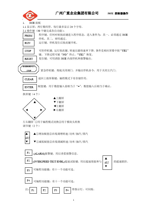
1. 505E 面板
1.1 显示屏:两行数码管,每行最多显示 24 个字母。
Statox 505 传感头操作手册说明书
Statox 505 Sensor HeadOperations ManualStatox 505 Sensor HeadOperations Manual1SAFETY INSTRUCTIONS 32STATOX 505 CONSTRUCTION 43INSTALLATION AND CONNECTION 5 3.1Warning 5 3.2Installation 5 3.3Electrical connection 63.3.1Statox 505 cable connection 73.3.2Connection diagram with Statox 501 Control Module in the 2-wire mode 83.3.3Connection diagram with Statox 501 Control Module in the 3-wire mode 103.3.4Connection diagram with Statox 502/503 Control Module in the 2-wire mode 123.3.5Connection diagram with Statox 502/503 Control Module in the 3-wire mode 134START –UP AND SERVICE 14 4.1Start - up and measuring mode 15 4.2Setting the realtime clock 16 4.3Setting the “service mode“ ou tput signal 17 4.4Calibrating the sensor 18 4.5Prooftest 20 4.6Info menu 21 4.7Test menu 225SENSOR REPLACEMENT 236MAINTENANCE 247SPARE PARTS AND ACCESSORIES 248STATUS- AND ERROR MESSAGES 25 8.1Status messages 25 8.2Error messages 26 9TECHNICAL DATA 27 9.1General transmitter data 27 9.2Sensor specific data 28 10CE-DECLARATION OF CONFORMITY 2921 Safety InstructionsThe Statox 505 sensor head is certified as explosion-proof safety equipment for group II category 2.The intended use is the measurement of toxic gas and oxygen concentration. Due to its intrinsically safe design it is safe to install and operate this product in zone 1 and zone 2.All relevant sensor parameters will be set automatically as soon as the sensor is connected.The following safety guidelines must be observed in particular:∙When installing and connecting the transmitter, the safety relevant electrical parameters and the protection class of the sensor head must comply with local standards (e.g. IEC 60079-14).∙If installed in a hazardous area, the power supply of the sensor heads must be intrinsically safe.Recommended products see connection diagrams in chapter 3.3 and in chapter 7 (accessories).∙The sensor head may only be operated within the specified environmental conditions.∙Damaged or not tightly closed housings may cause malfunction or loss of accuracy.All of the above warnings must be observed. Incorrect installation or connection will void the explosion proof rating and thus be dangerous to life and assets.34 2 Statox 505 constructionThe housing cover is attached with 4 bayonet screws. To open it, just turn these screws 90° counter - clockwise. The cover is secured to the housing with a steel strap.1 Mounting plate with 4 holes φ 10 mm2 Push buttons3 Display4 LED5 Programming interface (not for customer use)6 Cable terminal X17 Ground terminal8 Clamp for cable shield 9 cable gland M16x1,510 Sensor cover including filter support 11Securing strap for sensor cover167113 Installation and connection3.1 WarningIf the sensor head is installed in hazardous areas, the power supply must be intrinsically safe. Observe the safety - relevant specifications of sensor head, cable and barrier respectively intrinsically safe repeater.Caution:Do not install the sensor unless the sensor head has been connected to the power supply.The following specifications must be observed:U o, I o, C o, L o :certified repeater specificationsU i, I i, C i, L i : sensor head specifications (→ technical data)C L = cable capacity in pF/mL L = cable inductivity in nH/ml = cable length in mThe allowable cable length is defined in most cases by the cable capacity:l max = C o / C L (C i is negligible).Recommended cable type: see chapter 3.3.3.2 InstallationInstall the sensor head sensor downwards. Use stainless steel screws or insulate screws from mounting plate to avoid corrosion. In case of potential static voltage, ground the sensor head.The sensor head can be mounted to a wall with2 or 4 screws without opening the housing:Alternatively it can be mounted to a horizontalor vertical pipe. Statox 505 pipe mounting kitsare listed in chapter 7 accessories.5Statox 505 drilling plan and dimensions3.3 Electrical connection∙Use cable with 2 or 3 x ≥ 0,75 mm² with close - mashed shield, outer diameter ca. 6 mm(e.g. type Oelflex 415 CP3 X 0,75).∙Advantage of 3 - wire operation:In the two wire mode, the output signal for service and system failure is the same (2 mA).In the 3 - wire mode you can differentiate between “service” (non - critical = 2 mA) and “failure”(critical = 0 mA).∙If connecting the Statox 505 sensor head to a Statox 501 control module, follow the connecting diagrams in the chapters 3.3.2 and 3.3.3.If connecting the Statox 505 sensor head to a Statox 502/503 control module, follow the connecting diagrams in the chapters 3.3.4 and 3.3.5.If connecting the Statox 505 sensor head directly to a PCS, observe the following connecting diagram.In case of 2-wire-mode use only terminals 1 and 2.Statox 505 PCS63.3.1 Statox 505 cable connection∙Use cable with 2 or 3 x ≥ 0,75 mm² with close – mashed shield, outer diameter ca. 6 mm(e.g. type Oelflex 415 CP3 X 0,75).∙Do not install the sensor unless the sensor head is connected to the power supply.∙Run 20 cm (8 in) of cable through the cable gland.∙Strip the cable down to the shield. (A)∙Shorten the shield to 10 mm (0,4 in) and bend it backward. Make sure it does not touch the housing. (B)∙Connect the wires as shown in the schematics. The terminal is plugged in. Remove it for easy installation.∙Draw the cable back until the shield matches the clamp∙Fasten the cable gland.∙Secure the shield with the clamp. Good contact provides best protection from electromagnetic interference.∙Plug the terminal in.∙When the sensor head is connected to the power supply, the LED starts flashing for a short time and the display shows the software index.∙Now install the sensor (see chapter 4).A B C123Ø 5 - 7 mmX173.3.2 Connection diagram with Statox 501 Control Module in the 2-wire modeBefore connecting the sensor head, select the appropriate program. Refer to the Statox 501 operations manual and the program overview.3.3.2.1 2-wire mode installation in non hazardous areas83.3.2.2 2-wire mode installation in hazardous areasCaution: Incorrect connection of the intrinsically safe repeater might destroy it. Please take care for correct polarity and avoid short circuits.Repeater forms a current source: the terminal numbers on the drawing below refer to repeater type 9160/13-11-11s from manufacturer R.Stahl Schaltgeräte GmbH (or Siemens type 7NG4124-0AA00).It requires an extra power supply and forms a current source at clamps 1 and 2.A1 A2 SF 4-20mA A1 A2 Horn SFRepeater forms a current sink: the terminal numbers on the drawing below refer to repeater type9160/13-10-11s from manufacturer R.Stahl Schaltgeräte GmbH. It requires an extra power supply and forms a current sink at clamps 1 and 2.A1 A2 SF 4-20mA A1 A2 Horn SF93.3.3 Connection diagram with Statox 501 Control Module in the 3-wire modeBefore connecting the sensor head select the appropriate program. Refer to the Statox 501 operations manual and the program overview.3.3.3.1 3-wire mode installation in non – hazardous areasA1 A2 SF 4-20mA A1 A2 Horn SF103.3.3.2 3-wire mode installation in hazardous areasCaution: Incorrect connection of the intrinsically safe repeater might destroy it. Please take care for correct polarity and avoid short circuits.Repeater forms a current source: the terminal numbers on the drawing below refer to repeater type 9160/13-11-11s from manufacturer R.Stahl Schaltgeräte GmbH (or Siemens type 7NG4124-0AA00). It requires an extra power supply and forms a current source at clamps 1 and 2.Repeater forms a current sink: the terminal numbers on the drawing below refer to repeater type 9160/13-10-11s from manufacturer R.Stahl Schaltgeräte GmbH. It requires an extra power supply and forms a current sink at clamps 1 and 2.operations manual and the program overview.3.3.4.1 2-wire mode installation in non-hazardous areas3.3.4.2 2-wire mode installation in hazardous areasCaution : Incorrect connection of the intrinsically safe repeater might destroy it. Please take care for correct polarity and avoid short circuits. The terminal numbers on the drawing refer to repeater type 9160/13-11-11s from manufacturer R.Stahl Schaltgeräte GmbH (or Siemens type 7NG4124-0AA00). It requires an extra power supply and forms a current source at clamps 1 and 2. Plant = hazardous area Non hazardous area Power supply X1 Power supply X1 RepeaterStatox 502/503 Statox 502/503operations manual and the program overview.3.3.5.1 3-wire mode installation in non-hazardous areas3.3.5.2 3-wire mode installation in hazardous areasCaution : Incorrect connection of the intrinsically safe repeater might destroy it. Please take care for correct polarity and avoid short circuits.The terminal numbers on the drawing refer to repeater type 9160/13-11-11s from manufacturer R.Stahl Schaltgeräte GmbH (or Siemens type 7NG4124-0AA00). It requires an extra power supply and forms a current source at clamps 1 and 2. Plant = hazardous area Non hazardous area Power supply X1 Power supply Repeater X1 Statox 502/503 Statox 502/5034 Start –up and serviceSensor head keyboard:Press UP and DOWN at the same time to enter the menu.Increase / decrease the displayed parameter.Press and hold button for fast forward.RESET: One level up in the menu.ENTERTimeout: The sensor head returns automatically into the measuring mode if no key is pressed for more than 5 minutes.4.1 Start - up and measuring mode∙As soon as the sensor head is connected to the power supply, it starts a self test and shows the software index.∙Now install the sensor and filter. Please observe the handling instructions in chapter 5 !∙Remove the yellow protection cap from the sensor cover!∙As soon as the sensor is connected, the sensor head displays the parameter version, the gas to be detected, the measuring range and the best before date of the sensor. As soon as zero has stabilized, the instrument goes into the measuring mode. The green LED starts flashing.As long as the sensor head is not ready, the output signal is in the system fail mode, i. e. 2 mA when operated in the 2 wire mode, 0 mA when operated in the 3 wire mode.∙When the sensor head has completed the start – up sequence, you can start setting the real time clock (see chapter 4.2) and the service mode output signal (see chapter 4.3).4.2 Setting the realtime clock∙The clock is set ex works to CET. Please set it to your local time to make sure you get correct protocols of calibration and alarms.∙The clock has a back-up battery to save the time setting when power is disconnected.∙The segments flashing can be set with the up / down buttons.∙You can leave the time set menu by pushing the reset button.4.3 Setting the “service mode“ output signal∙The following table shows the potential modes and outputs.Notice: During the sensor replacement in the REPLACE menu, the sensor head remains in the service mode - even if no sensor is connected!∙If the sensor head is operated as a safety relevant device according to EN 50402 (Functional Safety) the output in the service mode must be 2 mA !4.4 Calibrating the sensor∙ Sensor head and sensor must have the same temperature!∙ You need a Statox 505 calibration adapter (art.no. 570505), a gas tubing 4x1 mm (art.no. 556710) and span gas (acceptable gas concentrations see chapter 9.2). If the environment is not clean, you need synthetic air for zeroing.∙ In case the calibration fails for whatever reason, the sensor head will continue to operate with the existing parameters, but the display will alternate showing the measured value and ZERO ADJ or CALIB until a calibration procedure has been completed.∙ O 2-sensors do not require a zero adjustment, as their output in pure nitrogen is nearly 0 nA. The span calibration can be done with clean ambient air or synthetic air.Procedure∙ Affix the adapter on the sensor cover until it catches (clockwise rotation). ∙ Connect the calibration adapter to the span gas cylinder.∙ Enter the service menu and select code 11 to enter the calibration routine. Set Zero.∙ Push ENTER button. As soon as the display shows GAS ON, open the valve. The gas flow should be ca. 20 l/h (300 ml/min). If you want to avoid span gas to be released into the environment, you can connect an active carbon filter art.no. 806488 to the exhaust of the gas adapter. Make sure there is no pressure building up in the adapter!∙ The display will show GAS.IS.ON until the reading is stable. Then it will show CONCENT? Now press ENTER . The display will now show the concentration of the recently used span gas. If you have used a gas with different concentration, adjust with the up / down buttons and confirm with ENTER .∙ When the display shows DONE , press ENTER to display the present concentration. Now close the regulator and remove the calibration adapter (clockwise rotation).∙ To return to the measuring mode, press ENTER again. The green LED starts flashing. If you fail to press ENTER , the sensor head will return to the measuring mode automatically after a timeout of 5 minutes. Calibration adapter4.5 Prooftest∙ A prooftest provides a verification of the transmitter performance under field conditions. It must be performed in regular intervals, if the transmitter is used as a safety relevant device. As long as the menu “Prooftest” is active, the output signal is set to 2 or 4 mA. In case the entire alarm chain must be tested, this must be done in the measuring mode.∙You need the Statox 505 calibration adapter art.no. 570505, a gas tubing 4x1 mm , art.no. 556710 and span gas with a concentration within the measuring range, preferably close to the alarm threshold.∙Affix the adapter on the sensor cover until it catches (clockwise rotation).∙Connect the gas adapter to the span gas cylinder.∙Enter the service menu and choose code 99 to enter the proof test routine.∙As soon as the display shows PROOF, open the valve and press ENTER. The gas flow should be ca.20 l/h (300 ml/min). If you want to avoid span gas to be released into the environment, you canconnect an active carbon filter art.no. 806488 to the exhaust of the gas adapter. Make sure there is no pressure building up in the adapter!∙The display will show the present concentration. Wait until the signal is stable before reading.∙Close the gas regulator and remove the calibration adapter (clockwise rotation).∙Return to the measuring mode by pushing the RESET button, stepping upward in the menu until you reach the measuring mode.∙If a new calibration is necessary proceed according chapter 4.4.∙Special timeout: If you do not push a button for 30 minutes, the transmitter returns automatically to the measuring mode.∙ A 2- or 3-time LED flashing during the proof test signalizes a periodical hardware test.∙This menu provides information about alarm history and sensor parameters.∙The exposure recording starts as soon as the end of the measuring range is exceeded.You can access the most recent 3 alarm events (start, end of range and end). The alarm events are not listed chronologically. For oxygen sensors only: the exposure recording starts as soon as the measured value drops below the detectable limit (see chapter 9.2).∙The total exposure information (DOSIS) is not updated permanently. Exposure by calibration is neglected. The maximum exposure reading depends on the measuring range. It is either 9,99 or 99,9 or 999 ppm * min.∙The total exposure recording is inactive for oxygen sensors.∙The calibration factor is a parameter used by the microprocessor. It cannot be used to obtain information about the sensor signal.∙In order to check the signal loop, the sensor head can generate 4, 12 and 20 mA.Caution: this might trigger an external alarm!∙The display can be tested by displaying a sequence of fonts and patterns.∙The sensor head can also display temperature.5 Sensor replacementPlease observe the precautions to avoid electrostatic voltage, when handling electronic devices. To avoid the sensor from being removed, while exchanging data with the sensor head, enter the service menu before you remove it. In the menu REPLACE the sensor can be replaced without generating a system failure alarm (see chapter 4.3). During the sensor replacement the sensor head will remain in the service mode.Handling instructions:still remaining in the service mode. After pushing theENTER button, or after a timeout of 30 min the sensor6 Maintenance∙Clean the Statox 505 with a humid wipe. Do not use detergents, solvents or steam jet.∙Inspect the housing and the O-rings for damage and pollution so that gas can securely access the sensor.∙If the sensor head is used in extremely harsh environment, an extra spray shield can be installed.Calibrate the sensor with the spray shield installed. Contact Compur Monitors for technical support!∙If the Statox 505 sensor head is used as a safety relevant device in terms of functional safety standard (EN 50402, IEC 61508), a regular proof test is mandatory (see chapter 4.5).7 Spare parts and accessoriesSpare sensors and technical data see chapter 9.2 !8 Status- and Error messages 8.1 Status messages8.2 Error messagesIf there is no display at all, check fuse and polarity. Fuse replacement by authorised personnel only.Critical errors set the output signal to 2 mA in the 2 – wire mode or to 0 mA in the 3 – wire mode. Non critical errors normally occur during maintenance or calibration. They have no impact on the system status.9 Technical data9.1 General transmitter dataProduct name: Statox 505 TransmitterType: 5375Manufacturer: COMPUR Monitors GmbH & Co. KG, D-81539 München Measuring principle: electrochemicalOperating temperature: -30°C to +60°C / -22° F to 140° FStorage temperature: -30°C to +60°C / -22° F to 140° FHumidity: 0 to 99% r.h. (non condensing)Pressure: 900 to 1100 hPaAccuracy at calibration point: +/- 10%Power supply: 12 -28 VDC, max. 22mAConnection: 2- or 3-WireOutput signal: 4 - 20 mA, max. load 700 Ohm∙In service mode: 2 or 4 mA adjustable∙In system fail mode: 0 mA in 3 - wire mode, 2 mA in 2 - wire mode∙Overrange: 22 mADisplay: 8-digits, 14 segmentsDimensions (HxWxD): 225 x 180 x 90 mm / 8,9 x 7,1 x 3,5 in (incl. mounting plate) Weight: 1040 g / 36,7 ounce (incl. mounting plate)Housing material: ABS chromium plated / stainless steelProtection class EN 60529: IP 65Operation position: Sensor downwardsEMC: EN 50270ATEX: Ex ib IIC T4 (EN 60079-0 and EN 60079-11)Application: II 2 GEC type examination certificate: BVS 09 ATEX E 104Parameters: U i: max. 28 VDCI i:max. 93 mA , P i = 650 mWInternal capacity C i: neglectibleInternal inductance L i: neglectibleFunctional safety: SIL 2M ore detailed information with regards to functional safety seeStatox 505 functional safety document art.no. 570555.9.2 Sensor specific data10 CE-Declaration of conformitySpecifications are subject to change without notice, and are provided only for comparison of products. The conditions under which our products are used, are beyond our control. Therefore, the user must fully test our products and / or information to determine suitability for any intended use, application, condition or situation. All information is given without warranty or guarantee. Compur Monitors disclaims any liability, negligence or otherwise, incurred in connection with the use of the products and information. Any statement or recommendation not contained herein is unauthorized and shall not bind Compur Monitors. Nothing herein shall be construed as a recommendation to use any product in conflict with patents covering any material or device or its use. No licence is implied or in fact granted under the claims of any patent. Instruments are manufactured by Compur Monitors GmbH & Co. KG, Munich.The General Conditions of Supply and Service of Compur Monitors GmbH & Co. KG, Munich, are applicable.Compur Monitors GmbH & Co. KGWeißenseestraße 101D-81539 MünchenTel.: ++49/89/ 6 20 38 268Fax : ++49/89/ 6 20 38 184E-Mail:****************5375 000 998 07 09 / 02.19 570553。
505操作
一.505控制器常用键功能:PRGM——编程RUN——运行RESET——复位STOP——正常停机(需要按YES或NO键确认)F1——报警F2——超速实验[F2+ADJ(上升)]F3——串级控制(阀前压力控制,需要按YES或NO键确认)SELECT——选择SPEED——速度AUX——功率限制KW——功率(负荷)显示CLEAR——清除ENTER——回车(确认)EMERGENCY SHUTDOWN————紧急停车二.PRGM————编程键一般情况下用户不能动,一般由厂家和DCS设计单位联合来完成编程,编程时设计有密码。
三.通常模式下启动(505面板操作)通电——505控制器自检(约1分钟)——自动跳到CONTPOLLING PARAMETER——如果有报警(F1 PUSH RUN/PROGRAM键红灯亮),按F1键观察报警条目。
报警包括(MPUFAILED转速传感器故障。
KW INPUT FAILED功率传感器故障。
OVER SPEED超速等)启动前应按RESET键复位报警,当无报警存在时,F1红色灯熄灭,方可启动。
启动前保证主汽阀处于全关状态。
按RUN键运行,505转速设定值按照编制的程序上升500rpm,可按SPEED键观察。
此时调节阀门逐渐全部打开,可按ACTR键观察。
逐渐打开主汽阀冲转,当转速达到500rpm设定值时,调节阀门回缩到某一稳定位置,505接替控制。
当预先编制的低暖机时间(25分钟)达到时,505自动控制转速上升到1200rpm高暖机转速。
如果需要延长暖机时间,可通过按SPEED键找到STATUS后,按NO键终止自动顺序,从而人为延长暖机时间。
当按SPEED键找到STATUS偶,按YES键又可以恢复到自动顺序控制状态,505将按照编程制好的程序继续自动控制。
如果希望减短暖机时间,可通过按SPEED键找到STEPT后,按转速立刻上升或下降(注意:转速设定值不能设定在临界转速避开范围内1450~2250rpm)。
建伍csp505音箱说明书
建伍csp505音箱说明书
1定时设置。
按下菜单/确认按钮,按向下按钮,选择定时设置,按菜单/确认按钮进入子菜单。
2添加定时。
选择添加定时,按菜单/确认按钮进入子菜单。
3音乐定时。
选择音乐定时,按菜单/确认按钮进入选项设置。
4按向下或者向上按钮选择调整的选项,按向左或者向右按钮调整时间,选择播放的日期及分区。
5按向下或者向上按钮选择调整的选项,按向左或者向右按钮勾选选项,可以选择播放规定的曲目。
6按向下或者向上按钮选择调整的选项,按向左或者向右按钮勾选播放的模式,按菜单/确认按钮保存设置。
长虹冰箱 BCD-505WP9BH 使用说明书
使用说明书电冰箱★ ★ 使用前请仔细阅读说明书请妥善保存 以备查阅BCD-505WP9BH目录产品概述产品特点..................................................................................... 各部分构件名称..........................................................................使用须知安全注意事项......................................................................... 使用准备................................................................................使用说明功能介绍............................................................................. 食物储藏............................................................................ 食物储藏小常识.................................................................保养与服务保养与清洁....................................................................... 冰箱工作时的非故障现象、简单故障分析与排除...............技术数据、装箱单产品中有害物质的名称及含量表保修凭证技术数据................................................................................... ...........................................产品中有害物质的名称及含量表 保修凭证.................................................................................. 装箱单.. (1)23~67~910~1213~1417~1819~202123242215~16尊敬的用户:感谢您选择长虹电冰箱!★使用前请仔细阅读本说明书,并保存以供参考。
- 1、下载文档前请自行甄别文档内容的完整性,平台不提供额外的编辑、内容补充、找答案等附加服务。
- 2、"仅部分预览"的文档,不可在线预览部分如存在完整性等问题,可反馈申请退款(可完整预览的文档不适用该条件!)。
- 3、如文档侵犯您的权益,请联系客服反馈,我们会尽快为您处理(人工客服工作时间:9:00-18:30)。
一、505控制器常用键功能:
PRGM——编程 RUN——运行 RESET——复位
STOP——停止(需要按YES或NO键确认)
F1——报警 F2——超速实验[F2+ADJ(上升)]
SELECT——选择 SPEED——速度
AUX——功率限制 KW——功率(负荷)显示
CLEAR——清除 ENTER——回车(确认)
EMERGENCY SHUTDOWN——紧急停机
二 、PRGM——编程键
一般情况下用户不能动,一般由厂家和DCS设计单
位联合来完成编程,编程时设计有密码。
三、通常模式下启动(505面板操作)
通电——505
控制器自检(约1分钟)——自动跳
到CONTROLLING PARAMETER——
PUSH RUN/PROGRAM 如果有报警(F1
键红灯亮),按
F1键观察报警条目。报警包括(Speed Probe
#1 Failed或Speed Probe #2 Failed转速传感器#1或传感
器#2故障、Cascade Input Failed阀前压力传感器故障、
Kw Input Failed功率传感器故障、OVER
SPEED超速等)
启动前应按RESET键复位报警,当无报警存在时,
F1红色灯熄灭,方可启动。启动前保证主汽阀处于全关
状态。
按RUN键运行,505转速设定值按照编制的程序上
升到600rpm,可按
SPEED键观察。此时调节阀门逐渐全
部打开,可按ACTR键观察。逐渐打开主汽阀冲转,当
转
速达到600rpm设定值时,调节
阀门回缩到某一稳定位置,
505接替控制。当预先编制的低暖机时间(30分)达到时,
505自动控制转速上升到1200
rpm高暖机转速。如果需要
延长暖机
时间,可通过按SPEED键找到STATUS后,按
NO键终止自动顺序,从而人为延长暖机时间。当按SPEED
键找到STATUS后,按YES键又可以恢复到自动顺序控制
状态,505将按照编制好的程序继续自动控制。如果希望减
短暖机时间,可通过按SPEED键找到STEPT后,按
键立刻提升降低转速,或按ENTER后,直接输入转速设定
值,转速立刻上升或下降(注意:转速设定值不能设定在临
界转速范围内1350~2250rpm)。转速达到3000 rpm后稳定
运行。
若需要紧急停机,可按EMERGENCY SHUTDOWN
紧急停机键,调节阀门立刻关闭停机。或按STOP键后再按
YES平稳停机,调节阀门缓慢关闭停机。
四、通常模式下启动(DCS操作)
根据DCS设计,从DCS画面上可完成报警复位
(RESET)、启动(RUN)、升速/降速
功能。
五、执行器标定测试(拉阀试验)
注意:A.拉阀试验一般在开机前进行,用来检验调速
器的调速性能。
B. 拉阀试验前主汽门必须关闭,即切断汽
源,这样才能保证在开启调节阀时蒸汽不
进入汽轮机。因在执行这一操作时,超速
检测及其继电器被屏蔽掉了。故必须切断
汽源,以防汽轮机超速。
C.进行拉阀试验过程如下:
1. 按505面板上RESET(复位)键,进行系
统RESET(
复位)指令。
2.
按505面板上EMERGENCY SHUTDOWN
(紧急停机)键,将505的紧急停机触点闭
合。
3.
按505面板上ACT键,然后按下翻键直到
出现Stroke Actuators-dsbld,Steam Must be
Off(确认主汽门已经切断了汽轮机的汽
源)。
4.按YES键确认,然后下翻箭头直到屏幕出
现Manually Adjust—Enabld,Stroke
ValveXXX. Xx 在该屏幕显示下按上
升、下降键将以5%/秒的速率在0-100%之
间改变阀门的输出电流。这样就能进行执
行机构(油动机)和调节汽阀的动作实验。
任何时候按YES键将允许直接输入设
定值 。当允许ENTER方式输入时,将显
示信息Manual。在Manual方式下按
ENTER
键,输入要求的设值,再按一次
ENTER
键。这将使执行机构输出立即跃变
至指定位置。任何时候按上升、下降键或
NO键将返回到Enable(投入)方式。
当标定结束时,505所显示的0~100%
阀门位置必须等于0~100%的实际阀门行
程。按两次CLEAR键来保存更改值并退
出标定方式。
六、超速实验:
1.超速实验一般在各种静态实验合格的前提下,
初次并网前进行。
2. 进行超速实验时,同时按OSPD键和Adjust Up
(提升)键,转速给定值将升高,当转速给定值升高至
高于调速器上限转速设定值(3150rpm)时,OSPD键中
的投入超速实验LED(发光二极管)将亮起。如果此时
释放OSPD键,转速给定值将返回到调速器上限转速设
定值(3150rpm)。
一旦汽轮机转速达到505调速器的内部
OVERSPEED TRIP LEVEL(超速跳闸转速)设定值
(3250 rpm)。OSPD键的LED(发光二极管)就闪烁且
屏幕闪烁显示“Speed〉Trip”信息。当汽轮机机械超速
保护动作后,机组就将因超速而跳闸停机。
如果在超速实验LED闪烁时释放OSPD键,机组
因超速而跳闸停机。
七、发电机功率控制操作:
1.功率限制:按AUX键,上行显示的是实际发电机功率,
下行显示的是505设定功率限制值,实际
功率永远超不过设定功率。设定值可进行
调整,调整范围(6000~9000KW)
2. 功率控制:按KW键,上行显示的是实际发电机功率
的百分数,下行显示的是505转速设定值,
此转速设定值对应着功率的设定,设定值
可进行调整,每转对应60千瓦,最大转速
设定值为3150rpm,对应功率为9000KW。
注意:发电机并网瞬间,505设置了一个最小功率
(约为300KW左右)。即发电机并网后自
动带上300KW左右负荷,505转速设定值
自动上升5 rpm,防止逆功产生。
八、继电器检校
警告:此操作须在汽轮机停机条件下完成
1. 在Service模式下的Force Relay Outputs菜单可对505
继电器开关状态进行检校 。
1. 将Force Relays置为yes
2. Force Relays Enabled将显示检校允许状态
3. 依次用AD键将SHUDDOWN、ALARM、#1—
#6RELAY状态由NO改为YES,并用万用表检测其
开关状态
4. 检测完毕后,应将RELAY状态由YES改为NO。
洛阳发电设备厂研究所
2010年11月8日