日本费加罗FIGARO硫化氢传感器 TGS825
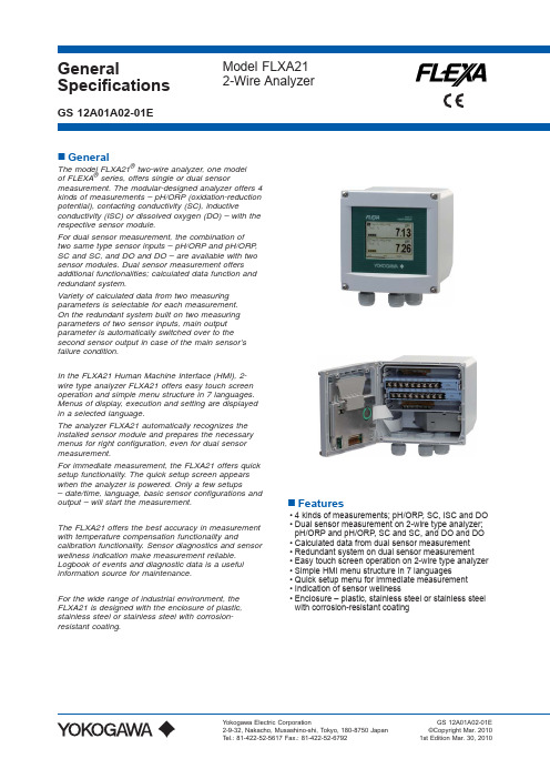
横河FLXA21新变送器说明书
All Rights Reserved. Copyright © 2010, Yokogawa Electric Corporation
2
with Pt100 Linearity: ±0.4 ºC Repeatability: ±0.1 ºC Accuracy: ±0.4 ºC
2-2. Conductivity (SC)
In the FLXA21 Human Machine Interface (HMI), 2wire type analyzer FLXA21 offers easy touch screen operation and simple menu structure in 7 languages. Menus of display, execution and setting are displayed in a selected language.
■ Input Range Conductivity: min.: 0 μS/cm max.: 200 mS x (Cell constant) (over range 2000 mS/cm) Resistivity: min.: 0.005 kΩ / (Cell constant) max.: 1000 MΩ x cm Temperature: Pt1000: -20 to 250 ºC Pt100: -20 to 200 ºC Ni100: -20 to 200 ºC NTC 8k55: -10 to 120 ºC Pb36(JIS NTC 6k): -20 to 120 ºC
神视传感器
SUNX全球网络
ƹ⌆Ͼ⚍ ƹ(8523( 3DQDVRQLF(OHFWULF:RUNV (XURSH $* ƹЁ ϰफѮഄऎϾ⚍ ƹ&+,1$ ($67$6,$ 3DQDVRQLF(OHFWULF:RUNV &KLQD &R/WG ᔙࢶᇷႂߔథᬌМՂ 3(:.5 ᭽
备有5m电缆长度型(标准:2m或3m)
·型号表
种 类
SUS安装支架型 PVC安装支架型 PFA安装支架型 PVC安装支架型 通用型 耐化学品型
标 准
EX-F71 EX-F71-PN EX-F72 EX-F72-PN EX-F61 EX-F61-PN EX-F62 EX-F62-PN
5m电缆长度
EX-F71-C5 EX-F71-PN-C5 EX-F72-C5 EX-F72-PN-C5 EX-F61-C5 EX-F61-PN-C5 EX-F62-C5 EX-F62-PN-C5
·MS-EX-F6-1 (PFA安装支架)
·MS-EX-F6-2 ·SL-CP1 ·SC-PK (吸附外连接器) (连接器底帽) (PVC安装支架) 每套8个 每套10个
·MS-SL-2 (部件安装基座)
4 3 2
FZ-10
·MS-EX-F7-3 (PVC安装支架)
1
规格
传感器 种 类 NPN输出型 PNP输出型 型号 通用型 SUS安装支架型 EX-F71 EX-F71-PN PVC安装支架型 EX-F72 EX-F72-PN EX-F61 EX-F61-PN 耐化学品型 PFA安装支架型 PVC安装支架型 EX-F62 EX-F62-PN
神视网页:/
1
特殊用途传感器篇产品目录
漏液/液面检测
SGX Infrared Single Gas Sensor for Hazardous Envir

___________________________________________________________________________________________Whilst SGX has taken care to ensure the accuracy of the information contained herein it accepts no responsibility for the consequences of any use thereof and also reserves the right to change the specification of goods without notice. SGX accepts no liability beyond the set out in its standard conditions of sale in respect of SGX Europe Sp. z o.o. Building 11Ligocka St. 103, 40-568 Katowice, PolandT: +48 (0) 32 438 4778E:**************************IR1 Single Gas Series DatasheetInfrared Single Gas Sensor for Hazardous Environments(Portable and Fixed Systems)The SGX infrared sensors use the proven Non-Dispersive Infrared (NDIR) principle to detect and monitor the presence of gases. With an infrared source and specific filtering on the pyroelectric detectors mounted inside the optical/gas cavity, individual gases or types of gas can be identified and their concentrations determined.These sensors are suitable for reliable monitoring of gas levels in general safety applications where the sensor size is restricted and require a flameproof enclosure for hazardous environments.APPLICATIONS∙ Oil & Gas∙ Petrochemical ∙ Biogas∙Wastewater ∙ Utilities ∙ Steelworks∙ Confined Space Entry ∙ Indoor Air QualityFEATURES∙For detection of the following gases:o Carbon Dioxide (IR11 Series),o Hydrocarbons (IR12 series, IR13 series) o Acetylene (IR14 series) ∙Gas concentration ranges:o 0 - 5% Carbon Dioxide(also suitable for 0 to 0.5%v/v) o 0 - 100% Carbon Dioxide(also suitable for 0 to 10%) o 0 - 100%v/v Hydrocarbons(also suitable for 0 to 100%LEL) o 0 - 100%v/v Acetylene(also suitable for 0 to 100%LEL)∙ 16.6mm or 19.0mm sensor heights available∙ Embedded temperature sensor in some versions for improved temperature compensation∙ Shock-resistant IR Source version available on certain types∙ Diffused gas sampling via mesh ∙ Low power∙ Reference channel for self-compensation∙ Special gold plated optical gas cavity for stable signal levels∙ Operational in varying temperature, pressure and humidity∙ Fast response∙ Rugged stainless steel construction ∙ No moving parts∙ Immunity from ‘poisoning’ ∙Reliable fail-safe operation∙Certified: ATEX, IECEx, CSA and ULOPERATIONTo operate, the sensors must be interfaced to a suitable circuit for power supply, output amplification and signal processing. Sensor outputs require linearisation and compensation for ambient temperature variation using algorithms in the system firmware. This is necessary for sensors to meet their full performance specification. An embedded temperature sensor facilitates this compensation on certain types. Further compensation for pressure changes can also be made in an algorithm, provided there is a suitable input from a pressure sensor.A set of Application Notes is available from the SGX Sensortech Ltd website, to explain more about NDIR gas sensing and provide advice for the end-user on interfacing the sensors and processing signals.TECHNICAL SPECIFICATIONCONFIGURATIONSsuitable. The use of the sensor beyond these ranges will affect the sensor’s perf ormance.** All sensors use temperature compensated pyroelectric detectors except for IR1nBD variants which are uncompensated. This refers to a change in the DC voltage output only. Further temperature compensation is required for all sensor variants.HANDLING PRECAUTIONS1. Do not allow sensors to fall on the floor. This could cause IR Source filament breakage, damage to the pins and the gasentrance aperture.2. Do not apply mechanical force against the gas entrance aperture.3. Do not immerse sensors in water or other fluids.4. Protect the gas entrance aperture against dust ingress and sprayed materials.5. Anti-static handling precautions must be taken.PERFORMANCEFor test purposes, all data taken using the following conditions:- Performance as tested in the SGX IR-EK2 Evaluation Kit directly after calibration.- SGX linearisation and temperature compensation algorithms applied; see Infrared Sensor Application Notes.- IR Source Voltage 5V, square wave, at 4 Hz and 50% duty cycle. Running the IR Source at 3V will decrease performance due to lower output signals.- Ambient temperature (20°C) and pressure (101 kPa).- All gases diluted in dry nitrogen.- Performance for the Hydrocarbons refers to Methane only. Most other hydrocarbons will have an improved performance.- Performance data is the same for the supported IR Source variants (“_1” variants).- Refer to Application Notes for more information.(2) Production Test Limits, using standard test gases of Dry Nitrogen, 2%v/v Carbon Dioxide, 5%v/v Methane and 1.15%v/v Acetylene, where appropriate .(3) A 0.30 absorbance is equivalent to a 30% decrease in the Active peak-to-peak output.(4) The minimum detection level is the smallest detectable change in concentration based upon a 2 sigma variantion. The best detectable change occurs at 0% gas concentration due to the non-linear output of the detector (see Fractional Absorbance Curves).(5) Performance for most hydrocarbons will be better than for methane for equiavlent concentrations, as methane is one of the lower sensitive gases compared to other hydocarbons.(6) After linearisation using the recommended method of linearisation and based upon a calibration gas with a concentration >75% of the full-scale. (7) Using average Alpha and Beta coefficients based upon test data from the instrument in which the sensor is being tested. Refer to Application Notes for information on calculating Alpha and Beta coefficients. Accuracy can be improved by measuring each sensor over temperature to define specific Alpha or Alpha & Beta coefficients.(8) After sensor stabilisation and over a period of 8 hours.(9) Difference in response when changed from 0 %RH to 90 %RH.(10)Sensors can be used over a greater ambient pressure using pressure compensation of the concentration. An external pressure sensor will be requred for this.FRACTIONAL ABSORBANCE CURVESThese show the typical sensitivity versus concentration before linearisation for the range of gases. For further explanation, refer to the Infrared Sensor Application Notes.Primary Target GasesIR11GM_1IR12BD IR12EM IR12GM IR12GM_1 IR13BDOther Target GasesIR12GM_1IR12GM_1 IR12GM_1IR12GM_1CERTIFICATIONSCSAULATEXIECEXINSTRUCTIONS SPECIFIC TO HAZARDOUS AREA INSTALLATIONS(Ref: EU ATEX Directive 2014/34/EU)1. The IR1xxx Series Gas Sensing Heads are component-approved only and may not be used as stand-alone items in ahazardous area without further protection.2. The IR1xxx Series Gas Sensing Heads shall be protected in service. The Sensing Head shall be mounted in a protectiveenclosure such that an impact of 7 J in accordance with IEC 60079-0:2007 clause 26.4.2 from any direction shall not cause the impact head to make contact with the Sensing Head.3. The thermal resistance of the IR1xxx Series Gas Sensing Heads does not exceed 25 K/W. This shall be taken into accountwhen considering its surface temperature and the temperature classification of the equipment into which it is to be incorporated. Tests indicated that an internal ignition raises the temperature of the mesh by a further 4.2 K (including a 1.2 safety factor).4. The IR1xxx Series Gas Sensing Heads have not been assessed as a safety device (EHSR 1.5).5. There are no user-serviceable parts in the component.6. The end-user/installer shall be aware that the certification of the IR1xxx Series Gas Sensing Heads relies on the followingmaterials used in its construction, which are suitable for most common applications:Enclosure .................................. Stainless steelMesh ......................................... Stainless steelBushing ..................................... Epoxy resinIn accordance with the Note in EN60079-0:2006 clause 6.1, the end-user/installer shall inform the manufacturer of any adverse conditions that the IR1xxx Series Gas Sensing Heads may encounter. This is to ensure that the IR1xxx Series Gas Sensing Heads are not subjected to conditions that may cause degradation of these materials.7. The IR1xxx Series Gas Sensing Head is only certified for use in ambient temperatures between -20°C and +55︒C andshould not be used outside this range.8. The maximum input power of the IR1xxx Series Gas Sensing Head shall not exceed 2.5 W.9.10. The IR1xxx Series Gas Sensing Heads are dust-proof (IP5x) but offers no protection against the ingress of water. Whereprotection in excess of IP50 is required, the apparatus into which the IR1xxx Series Head is installed shall provide the necessary ingress protection (for example by fitting an external semi-permeable membrane).OUTLINE(All dimensions in millimetres; dimensions without limits are nominal)6-Pin Devices (See Configuration Table)7-Pin Devices (See Configuration Table)ConnectionsPin Connection1 +V DC detector input2 IR Source3 IR Source return4 Active detector output5 Reference detector output6 0 V input7 Temperature sensor: Thermistor (code E); LM60 (code G) (7-Pin Devices Only)Outline Notes1. Body dimensional tolerances 0.1 mm. Pin dimensional tolerances as indicated.2. For code J devices, this length is 19.0 mm; for code M devices it is 16.6 mm.3. IR1xxx Series sensors are designed to press-fit into PCB sockets. The end-user should choose a socket to accommodatethe full sensor pin length. This will ensure a stable mechanical location as well as good electrical contact. SGX Sensortech Ltd recommend the Wearns Cambion type 450-1813-01-03-00 single-pole solder mount socket with through hole, or a suitable equivalent.ACCESSORIESDust Membrane (DPP702964BA)Material PTFEAir Flow ≥6.8 l/hr/cm2(∆p 10mbar) Water Intrusion Pressure ≥210 mbarLaminated PTFE Thickness 0.28 mm (nominal)。
关于自络清纱器问题及解决方法
关于自络清纱器问题及解决方法1、支偏,指的是不是电清突然间一直不停的切纱?或者是单锭长时间下来都发生支篇切纱?1、1如果是突然间发生,可以更换一根管纱试试。
如果支偏设置很严格的话,如 7%, 8%,支偏无法以肉眼辨识。
只能将管纱拿到试验室秤其格林数,不过得注意这根管纱,所含支偏细纱到底有多长。
1、2如果长时间下来,都是固定一锭(例如#12锭)发生支偏切纱数值高。
可以将检测头与相邻的正常锭(例如11锭)交换,看看问题是不是仍然发生在原来的第#12锭,如果是,问题可能发生在机械问题,看看退绕中的管纱,经过检查槽时是否稳定。
管纱退绕时的张力、气圈关系着细纱通过检测槽时的稳定度。
当然,也可以更换评价电路版。
以过滤方式,将问题找出来。
1、3如果支偏乱切现象还是发生在原来的那个检测头(就是原来支偏乱清的第12锭检测头,目前在第11锭运转),该检测头可能需要校正,或是清洁。
1、4交换过检测头或是评价电路版的两个锭子,不要忘了先执行『单锭微调』。
结:其实,严格说来,支偏叁数的设定是否恰当,也关系着切纱数的徒然增加或减少。
细纱机纺出来的每根管纱,从满管道管脚,毛羽相差约 10%。
多出来的毛羽,都会视为支偏。
有SFI, SFI/D 功能的系统就可以分辨出来,不过设定太严也是会被切除。
因此,支偏设定太过严苛,当发生支偏切纱时,不妨看看是不是该锭正在退绕毛羽高的管脚纱。
尤其是天气湿度的变化,也会左右管纱毛羽的增减。
根据我的经验,发生支偏切纱过多,大多数都是因为设定太过严苛。
当然,这要在络筒机退绕稳定情况的前提之下。
2、支偏设定与条干CV%、长粗节、长细节是什么关系?2、1洛菲对支偏的定义,共分长错支、短错支两个通道。
设定叁数的方法很简单,只要输入当前绕取的细纱是多少支数( Ne, Nm, Tex)如:Ne 40,然後输入想切除的偏粗、偏细细纱支数,例如:Ne 35, Ne 45,控制相就会自动算出直径偏差百分比,以这百分比当成错支清除门槛。
4PH CiTiceL

4PH CiTiceL ®Performance CharacteristicsNominal Range Maximum Overload Expected Operating Life Output Signal Resolution Temperature Range Pressure Range Pressure Coefficient T 90 Response Time Relative Humidity Range Typical Baseline Range (pure air)Maximum Zero Shift (+20°C to +40°C)Long Term Output Drift Recommended Load ResistorBias Voltage Repeatability Output Linearity 0-5ppm20ppmTwo years in air1.7±0.3 µA/ppm <0.05ppm-20°C to +50°CAtmospheric ± 10%No data <80 seconds15 to 90% non-condensing 0 to +0.2ppm equivalent<0.07 ppm equivalent<2% signal loss/month 10ΩNot required 2% of signal LinearDoc. Ref.:4ph.p65Issue 4.7Mar 12, 20015g (approx.)NoneSix months in CTL container0-20°C 12 months from date ofdespatchPhysical CharacteristicsWeight Position Sensitivity Storage Life Recommended Storage TemperatureWarranty Period N.B.All performance data is based on conditions at 20°C,50%RH, and 1013mBarAll dimensions in mmAll tolerances ±0.15mm unless othewise statedEvery effort has been made to ensure the accuracy of this document at the time of printing. In accordance with the company’s policy of continued product improvement City Technology Limited reserves the right to make product changes without notice. No liability is accepted for any consequential losses, injury or damage resulting from the use of this document or from any omissions or errors herein. The data is given for guidance only. It does not constitute a specification or an offer for sale.The products are always subject to a programme of improvement and testing which may result in some changes in the characteristics quoted. As the products may be used by the client in circumstances beyond the knowledge and control of City Technology Limited, we cannot give any warranty as to the relevance of these particulars to an application. It is the clients’ responsibility to carry out the necessary tests to determine the usefulness of the products and to ensure their safety of operation in Cross-sensitivity DataCiTiceLs may exhibit a response to certain gases in a sample other than the target gas. 4PH CiTiceLs have been tested with a number of commonly cross-interfering gases and the results are given below. The table shows the typical response to be expected from a sensor when exposed to a given test gas concentration (relevant to safety, e.g. TLV levels).4PH Phosphine CiTiceL - Output vs Temperature020406080100120-20-101020304050Temperature (°C)O u t p u t % o f s i g n a l @ 20°C4PH Phosphine CiTiceL - Baseline vs Temperature-0.10.00.10.20.30.40.5Temperature (°C)B a s e l i n e p p m e q u i v a l e n t (n u l l e d @20°C )英国CT气体传感器 CITY城市技术气体传感器常用型号选型样本 CITY公司/IT公司/SENSORIC公司气体传感器选购指南 英国CT气体传感器快速选型产品系列用途3系列种类齐全的毒气气体传感器4系列主要应用于便携式气体检测仪5系列排放气体传感器系列7系列用于一般气体检测的传感器医用系列氧气传感器是专为呼吸及麻醉应用而设计的产品汽车系列用于汽车尾气排放分析仪MICROceL微型气体传感器Sensoric毒气传感器Sixth Sense一氧化碳传感器工业安全监测气体类型产品名称 使用寿命 量程 产品描述一氧化碳C O MICROceL CF2CF2E/F3E3E/F3ME/F4CF4CO4COSH7E7E/F9CFA7EA7E/FCO 2E 300CO 3E 300CO 3E 500 SE ZT3E/F2年空气中2年空气中2年空气中3年空气中3年空气中3年空气中2年空气中2年空气中3年空气中3年空气中3年3个月空气中3年空气中3年>3 years>4 years>2 years空气中3年0-1500ppm0-1000ppm0-500ppm0-2000ppm0-2000ppm0-2000ppm0-1500ppm0-1500ppm0-1500ppm CO0-500ppmH2S0-2000ppm0-2000ppm0-200ppm0-2000ppm0-2000ppm0-300ppm0-500ppm0-500p三电极一氧化碳传感器带内置过滤器二电极微型传感器二电极,带H2S过滤器三电极三电极,带H2S过滤器三电极,带H2S过滤器和mV输出板三电极微型,带H2S和SO2过滤器三电极微型四电极微型二气(CO和H2S)三电极微型三电极微型,带H2S和SO2过滤器二电极,使用寿命三个月四电极,带氢气补偿四电极,带H2S、SO2过滤器,和H2补偿两电极,有4系和7系等三种尺寸.三电极,有4系和7系等三种尺寸.三电极传感器,有4系和7系等三种尺寸.三电极,带H2S过滤器和4-20mA传输板0-500p mp硫化氢H 2 S MICROceL HS3H3HH3HH/LM3MH4COSH4H4HS7H7HH7HH/LM9HHEZT3HH2S 2E 30H2S 2E 50H2S 2E 50 SH2S 3E 100H2S 3E 100 SH2S 3E 302年空气中2年空气中2年空气中2年空气中2年空气中3年空气中2年空气中2年空气中2年空气中2年空气中2年空气中3个月空气中2年>18 月>18 月>4 years>4 years>4 years>18 months0-1000ppm0-1000ppm0-500ppm0-500ppm0-500ppm0-1500ppm CO0-500ppmH2S0-500ppm0-500ppm0-1000ppm0-500ppm0-500ppm0-200ppm0-200ppm0-30ppm0-50ppm0-50ppm0-100ppm0-100pMICRO三电极硫化氢传感器三电极传感器三电极传感器,高量程三电极传感器,对甲烷交叉干扰低三电极传感器,带mV输出板四电极微型二气传感器(CO和H2S)三电极微型传感器,高干扰三电极微型传感器三电极微型传感器三电极微型传感器,高干扰三电极微型传感器,对甲烷交叉干扰低二电极传感器,使用寿命三个月三电极传感器带4-20mA传输板两电极,有机电极、有4系和7系等三种尺寸.两电极,有4系和7系等三种尺寸.三电极,有4系和7系等三种尺寸.三电极,有4系和7系等三种尺寸.三电极,有4系和7系等三种尺寸.0-30ppm氧气O 2 4OX-14OX-27OX-VC/2C/2PNC/NC/NLHC/NLLC/SC/YMICROceL OXT7OX-VI-05I-01I-02I-04I-06I-08P-10P-40P-40F OS-65空气中1年空气中2年空气中2年空气中18个月空气中1年空气中9个月平衡平衡空气中9个月空气中1年空气中2年空气中2年3年6年6年3年4年4年2年2年2年0-30%0-30%0-30%0-30%0-30%0-30%0-1000ppm0-1000ppm0-30%0-30%0-30%0-25%0-100%0-35%0-35%0-100%0-100%0-25%0-21%0-21%0-1%0-65%微型传感器,塑料容器微型传感器,塑料容器微型传感器–塑料罐。
理研计器株式会社便携式气体检测器GX-3R Pro使用说明书
PT0C-1775便携式气体检测器GX-3R Pro使用说明书(PT0-165)理研计器株式会社邮编:174-8744 日本东京都板桥区小豆泽2-7-6网页 https://www.rikenkeiki.co.jp/1 产品概述 (5)1-1. 前言 (5)1-2. 使用目的 (5)1-3. 检测对象气体的确认方法 (6)1-4. 危险、警告、注意、注记的定义 (7)1-5. 标准及防爆规格的确认方法 (7)2 安全重要事项 (8)2-1. Japan Ex规格相关的重要事项 (8)2-2. 警告事项 (10)2-3. 注意事项 (11)2-4. ATEX/IECEx规格相关的安全信息 (13)3 产品的构成 (14)3-1. 主机及标准附件 (14)主机 (14)标准附件 (15)3-2. 各部的名称和功能 (16)主机 (16)电池单元 (17)LCD显示部 (18)4 警报动作 (19)4-1. 气体警报动作 (19)4-2. 故障警报动作 (22)4-3. 混乱警报 (23)混乱警报的蜂鸣器鸣响和灯闪烁动作 (23)混乱警报的发报和警报模式 (23)4-4. MAN DOWN警报 (24)MAN DOWN警报的蜂鸣器鸣响和灯闪烁动作 (24)MAN DOWN警报的显示和警报模式 (24)5 使用方法 (25)5-1. 使用之前 (25)5-2. 起动准备 (25)5-2-1. 锂离子电池单元(BUL-3R)的充电和安装 (25)5-2-2. 电池单元(BUD-3R)的安装 (29)5-3. 起动方法 (31)接通电源 (31)从电源接通到测量画面的跳转 (32)5-4. AIR校正 (35)AIR校正步骤 (35)5-5. 检测 (36)5-5-1. 基本动作流程 (37)5-5-2.测量模式 (38)5-6. 切断电源 (40)6 设定方法 (41)6-1. DISP模式 (41)6-1-1. 显示DISP模式 (41)6-1-2. DISP模式的显示内容 (41)6-2. DISP模式的设定 (44)6-2-1. PEAK值显示的清除 (44)6-2-2. 可燃性替换气体的选择 (45)6-2-3. 长寿命电池的设定 (47)6-2-4. 校正记录的显示 (48)6-2-5. BUMP记录的显示 (49)6-2-7. 显示上下反转设定 (51)6-2-8. 显示黑白反转设定 (52)6-2-9. 蓝牙的设定 (52)6-2-10. 蜂鸣器音量的调节 (53)6-2-11. 显示语言的设定 (53)6-3. 用户模式 (55)6-3-1. 显示用户模式 (55)6-3-2. 用户模式的设定项目 (56)6-4. 用户模式的设定 (57)6-4-1. BUMP测试 (57)6-4-2. 气体校正 (57)6-4-3. 校正期限设定 (57)6-4-4. BUMP测试的设定 (60)6-4-5. MAN DOWN警报设定 (65)6-4-6. 警报点设定 (67)6-4-7. 休息时间的启动/关闭 (69)6-4-8. 确认蜂鸣设定 (69)6-4-9. 自动背光的启动/关闭 (72)6-4-10. 背光的亮灯时间设定 (72)6-4-11. 按键音的启动/关闭 (73)6-4-12. DISP模式项目显示的启动/关闭 (73)6-4-13. CO2传感器的单位切换 (74)6-4-14. CO2传感器AIR校正的启动/关闭 (74)6-4-15. 时间设定 (75)6-4-16. 日期的格式设定 (75)6-4-17. 语言设定 (76)6-4-18. 用户密码设定 (77)6-4-19. ROM/SUM的显示 (78)6-4-20. 蓝牙的认证显示 (78)7 保养检查 (79)7-1. 检查的频度和检查项目 (79)关于维护服务 (80)7-2. 气体校正 (81)7-2-1. 气体校正的准备 (81)7-2-2. 气体校正的设定菜单 (83)7-2-3. AIR校正 (84)7-2-4. CO2校零 (86)7-2-5. 自动校正 (87)7-2-6. 自动校正的气缸设定 (88)7-2-7. 自动校正的校正浓度选择 (89)7-3. BUMP测试 (90)7-4. 清扫方法 (91)7-5. 各部件的更换 (92)7-5-1. 定期更换部件 (92)7-5-2. 过滤器的更换 (94)8 关于储存及废弃 (96)8-1. 储存或长期不使用时的处理 (96)8-2. 重新使用时的处理 (97)8-3. 产品的废弃 (97)9 故障检修 (98)9-1. 仪器的异常 (98)9-2. 指示值的异常 (100)10 产品规格 (101)10-1. 规格一览 (101)11 附录 (107)数据记录功能 (107)100%LEL=ppm换算表 (109)改废记录 (110)CE符合性声明书 (111)1 产品概述1-1.前言1产品概述感谢您本次购买便携式气体检测器GX-3R Pro(以下称“本仪器”)。
温度传感器简介
(二)热电偶产品简介 1、热电偶材料按分度号分为 B、R、S、N、K、E、J、T、WRe3- Wre25、Wre5- Wre26 等 10 个标准形式,此外还有一些非标丝材
可供选择。不同分度号的热电偶测温范围、优缺点也不相同,根据需要选择合适分度号的测温产品。
标准化热电偶的主要性能列表如下:
热偶品种
引脚说明:GND:地 VDD:可供选用的外部电源,不用时接地
21.036 28.946
37.005
℃
700
800
900
1000
mV
53.112 61.017
68.787 76.373
参考端非 0℃时校正表
℃
0
10
20
30
40
(校正值+相应温度 mV 值) mV
0
0.591
1.192
1.801
2.420
600 45.093
50 3.048
(三)DS18B20 数字温度传感器简介
2012/13 工控产品手册 pure-china@ 3
九纯健科技-传感与测控专家
温度产品手册
单位 镍铬-镍铜(康铜)热电偶(E 型) 热电动势 mV 与温度值对照表(参考端 0℃时)
℃
-200
-100
0
100
200
300
400
500
mV
-8.825
-5.237
0
6.319
13.421
1180
190
168.48 172.17
280
290
204.90 208.48
700
750
345.28 360.64
罗斯蒙特3051s差压液位变送器-产品说明书-中文
产品说明书00813-0106-4016, Rev UC2023 年 3 月Rosemount™差压液位变送器和 1199 远传密封件应用■液位、流量、压力、界面、密度■极热和极冷环境■腐蚀、堵塞或粘滞过程■卫生要求■特殊过程连接件成熟、可靠和创新的技术使用资产位号随时获取信息新发运设备包含一个唯一的二维码资产位号,您可以通过它直接从设备访问序列化信息。
通过此功能,您可以:■在您的 MyEmerson 账号上访问设备图纸、图表、技术文档和故障排除信息■优化维修和保持效率的平均时间■确保您定位了正确的设备■省去耗时的先定位和抄录铭牌再查看资产信息的工作罗斯蒙特液位变送器此液位变送器将世界先进的罗斯蒙特压力仪表与直接安装密封件相结合,全部集成为一个型号。
Rosemount 3051SAL、3051L 和 2051L型液位变送器■全焊接系统具备突出的系统可靠性■无线组态提供新数据访问■使用全面的过程连接产品、灌充液、直接安装或毛细管连接件和材料可连接到几乎任何过程■利用 QZ 选件量化和优化整个系统的性能内容成熟、可靠和创新的技术 (2)Rosemount 3051S 电子远程传感器 (ERS™) 系统 (6)Rosemount 3051S Scalable™液位变送器 (26)用于 Rosemount 3051SAL 的法兰密封件 (40)Rosemount 3051L 液位变送器订购信息 (65)Rosemount 2051L 液位变送器 (77)直接安装式密封系统订购信息 (86)远传安装式密封系统订购信息 (92)法兰密封件 (98)螺纹密封件 (123)卫生型密封件 (129)专业密封件 (144)技术规格 (153)产品认证 (173)尺寸图 (216)2023 年 3 月/Rosemount罗斯蒙特 Tuned-System ™ 组件优化结果罗斯蒙特 Tuned-System 组件在高压连接件上采用直接安装密封件,在低压连接件上则采用远程安装(毛细管式)密封件。
UVM-30紫外模块
深 三:超声波感应模块类:
1:CLX-311 超声波感应模块(小体积 46*19mm)
四:煤气感应模块类:
1:CLX-310 煤气感应模块(小体积 38*26mm)
五:通用 315M/433M 高频收发模块类:
1: CLX-2082:(315M/433M 接收模块)
2: CLX-682:(315M/433M 带解码接收模块)
立D
UVM30A
B
C
诚 市
圳
深
FG
9.0 9.0 10.0 2.2 3.5 0.5 1.5
脚位 功能
1
电源地 GND
2
信号输出 Vout
3
电源正 VCC
123
■ 注意
本传感器对可见光不敏感,无需再加滤光片; 中心孔为紫外线透射感应窗,请勿用任何物质遮盖,包括透明玻璃、塑胶片等; 如需清洁窗口,不能用酒精等溶剂类液体,请用棉棒醮清水轻轻擦拭。 安装时,不同的光线入射角度会有不同强度的信号输出,光线垂直入射时信号最强(电压输出数据为此 条件测得)。 由于周围物体反射的原因,人体实际所受紫外线辐射的强度比传感器测得的强度要高。
▉
深圳市诚立信传感技术有限公司
输出电压 (mV)
Sensor
多年专注铸就优秀品质 持续创新只为客户需求
■典型响应曲线
UVM-30紫外线传感器模块
1200
1100 1000
紫外线指数 0
UV Index
900
800
700
Vout(mV) <50 227 318 408 503 606
Sensor
多年专注铸就优秀品质 持续创新只为客户需求
■ 特点
专为需要高可靠性和精确性测量紫外线指数(UVI) 的场合所设计; 适合测量太阳光紫外线强度总量; 对照世界卫生组织紫外线指数分级标准 检测 UV 波长:200-370nm; 响应极快、全互换性; 采用具有专利的固体聚合物构造、防水防尘易清洗; 线性电压信号输出; 小尺寸,适用于移动电话等便携产品;
BOSCH 氧传感器 LSF4.2 标准
During the condensation water phase the heater power must be limited (by heater power duty cycling), to rule out thermo shock damage of the sensor ceramic, see measuring method Y 258 E00 007.
12 V
Maximum permif,max
- continuous:
12 ... 14 V
- max. 1 % of total life time
≤ 15 V
(exhaust gas temperature ≤ 850°C)
Technische Kundenunterlage Technical Customer Information
Y 258 K01 009-000e
Seite/Page Datum/Date
4 von/of 22 27.5.2003
1.4 Heater supply
Nominal voltage:
Heater voltage during condensation water phase VH,eff ≤ 4 V
Heater power reduction in condensation water phase
max. 100% of continuous operating voltage V H,eff,max after dew point end
≤ 16.5 V ≤ 28 V
Test voltage: (for tests in section 3 an 4)
13±0.1 V
- 1、下载文档前请自行甄别文档内容的完整性,平台不提供额外的编辑、内容补充、找答案等附加服务。
- 2、"仅部分预览"的文档,不可在线预览部分如存在完整性等问题,可反馈申请退款(可完整预览的文档不适用该条件!)。
- 3、如文档侵犯您的权益,请联系客服反馈,我们会尽快为您处理(人工客服工作时间:9:00-18:30)。
Applications:Features:TGS 825 - Special Sensor for Hydrogen Sulfide
* Hydrogen sulfide detectors/alarms* High sensitivity to low concentration of
hydrogen sulfide* Good repeatability in measurement* Uses simple electrical circuit* Ceramic base resistant to severeenvironment
The sensing element of Figaro gas sensors is a tin dioxide (SnO2) semiconductorwhich has low conductivity in clean air. In the presence of a detectable gas,the sensor's conductivity increases depending on the gas concentration inthe air. A simple electrical circuit can convert the change in conductivity toan output signal which corresponds to the gas concentration.
The TGS 825 has high sensitivity to hydrogen sulfide. The sensor can detectconcentrations of hydrogen sulfide as low as 5ppm, making it ideal forapplication in gas leak detection.
The figure below represents typical sensitivity char-acteristics, all data having been gathered at standardtest conditions (see reverse side of this sheet). The Y-axisis indicated as sensor resistance ratio (Rs/Ro) which isdefined as follows:Rs = Sensor resistance of displayed gases atvariousconcentrationsRo = Sensor resistance at 50ppm of hydrogenThe figure below represents typical temperature andhumidity dependency characteristics. Again, the Y-axis isindicated as sensor resistance ratio (Rs/Ro), defined asfollows:Rs = Sensor resistance at 50ppm of hydrogensulfide at various temp./humiditiesRo = Sensor resistance at 50ppm of hydrogensulfide at 20°C and 65% R.H.
Temperature/Humidity Dependency:Sensitivity Characteristics:
0.1110
10100Rs/Ro
Concentration (ppm)520502
Air
Hydrogensulfide0.5
0.40.60.8
1
3
-200204060Rs/Ro
5
R.H.0%
Ambient Temperature (°C)65%100%
2
深圳市深国安电子科技有限公司地址:广东省深圳市龙华新区牛栏前大厦C507
网址:www.singoan.com www.singoan.com.cn www.shenguoan.com 蒋小姐:134 2876 2631 电话:86 755-85258900ItemSymbolConditionSpecificationSensor ResistanceHydrogen sulfide at 50ppm/Air3k ~ 30kChange Ratio of Sensor ResistanceRs (Hydrogen sulfide at 50ppm/Air) Rs (Hydrogen sulfide at 10ppm/Air)0.45 ± .15
Heater ResistanceRoom temperature38.0 ± 3.0Heater Power ConsumptionVH=5.0V660 ± 55mW
Structure and Dimensions:1 Sensing Element:SnO2 is sintered to form a thick film onthe surface of an alumina ceramic tubewhich contains an internal heater.2 Sensor Base:Alumina ceramic3 Flame Arrestor:100 mesh SUS 316 double gauze
ItemSymbolRated ValuesRemarksHeater VoltageVH5.0±0.2VAC or DCCircuit VoltageVCMax. 24VAC or DC *PS15mW
Load ResistanceRLVariable*PS15mW
Standard Circuit Conditions:VH
VC
RL
Pin Connection and Basic Measuring Circuit:The numbers shown around the sensor symbol in the circuit diagram at theright correspond with the pin numbers shown in the sensor's structure drawing(above). When the sensor is connected as shown in the basic circuit, outputacross the Load Resistor (VRL) increases as the sensor's resistance (Rs) de-creases, depending on gas concentration.
Sensor Resistance (Rs) is calculated bythe following formula:
Rs = (-1) x RL
VC
VRL
Power dissipation across sensor electrodes(Ps) is calculated by the following formula:
Ps = 2VC x Rs 2
(Rs + RL)
Standard Test Conditions:TGS 825 complies with the above electrical characteristicswhen the sensor is tested in standard conditions as speci-fied below:Test Gas Conditions:20°±2°C, 65±5%R.H.Circuit Conditions:VC = 10.0±0.1V (AC or DC),VH = 5.0±0.05V (AC or DC),RL = 10.0kΩ±1%Preheating period before testing: More than 7 days
Electrical Characteristics:RsRs/RoRH
PH
Basic Measuring Circuit:um : mm19.5 ± 0.51.0 ± 0.05
13.5+ 0.3- 0.2
9.5 ± 0.3
11.0 ± 0.223.0 ± 1.0
3.0 ±
0.2
6.5± 0.
2
634251
45˚
45˚
深圳市深国安电子科技有限公司地址:广东省深圳市龙华新区牛栏前大厦C507
网址:www.singoan.com www.singoan.com.cn www.shenguoan.com 蒋小姐:134 2876 2631 电话:86 755-85258900