Z400操作手册-2.0
Cutler-Hammer ATC-400 控制转移开关快速操作指南说明书
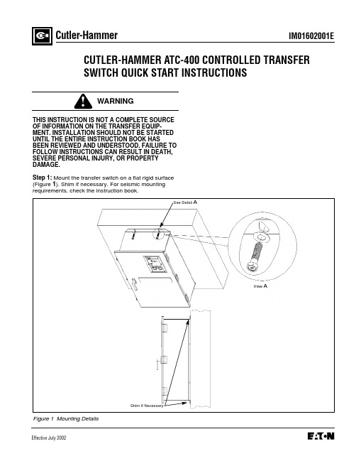
IM01602001EEffective July 2002Cutler-HammerCUTLER-HAMMER ATC-400 CONTROLLED TRANSFER SWITCH QUICK START INSTRUCTIONSTHIS INSTRUCTION IS NOT A COMPLETE SOURCE OF INFORMATION ON THE TRANSFER EQUIP-MENT. INSTALLATION SHOULD NOT BE STARTED UNTIL THE ENTIRE INSTRUCTION BOOK HASBEEN REVIEWED AND UNDERSTOOD. FAILURE TO FOLLOW INSTRUCTIONS CAN RESULT IN DEATH,SEVERE PERSONAL INJURY, OR PROPERTY DAMAGE.Step 1: Mount the transfer switch on a flat rigid surface (Figure 1). Shim if necessary. For seismic mountingrequirements, check the instruction book.Figure 1 Mounting DetailsShim If NecessaryView ASee Detail APage 2Effective 7/02Figure 2 300A, 3 Pole, Automatic Transfer Switch InteriorFuse Disconnect BlockEngine Start ContactsOptional Feature 37Fuse Disconnect BlockSource (S2) Power TerminalsPage 3Effective 7/02Tighten Cables Into TerminalsSee Detail BDetail BTypicalEngine Start Contacts(Red Terminals)Page 4Effective 7/02Figure 6 ATC-400 Logic (Utility Supplying Load)qqThe following lights must be ON:q Source 1 Available q Source 1 ConnectedPerform LED lamp test by depressing and holding. All LED’s should turn on.If not, contact factory for replacement.Page 5Effective 7/02Page 6Figure 7 ATC-400 (Rear View)Effective 7/02Page 7Effective 7/02qqqThe following lights must be ON:q Source 1 Availableq Source 1 Connectedq Source 2 AvailableThe following lights must be ON:q Source 1 Availableq Source 2 Availableq Source 2 ConnectedqqqIM01602001EPage 8Cutler-HammerPittsburgh, Pennsylvania U.S.A.Effective 7/02 (ISI)Style IM01602001E H01Printed in U.S.A.Step 10: ATH4/ATV4 Power Failure Test - Initiate a Load Test by simulating an actual power failure.(1) This should be done by opening the upstream breaker or fused disconnect switch.(2) If the ATS is Service Equipment Rated with no upstream disconnect, use the Normal Control Circuit Disconnect to simulate a power failure (Figure 10).This can be found in one of two places. The first would be located directly beside the normal breaker. The second would be located on the transformer panel/customer connection panel. The normal con- trol circuit disconnect is the disconnect markedNormal.The disconnect switch should be in the ON position for normal operation. Turning the switch to the OFF position will simulate a normal power out- age.Figure 10 Control Disconnect(3) The generator should start and the ATS should transfer to Emergency.(4) After transfer, close the upstream breaker, or close the Normal Control Circuit Disconnect. The TDEN timer should begin counting, and, when com- plete, the ATS should transfer to Normal. The En- gine Cooldown Timer should time out and shut the emergency power unit down.NOTICEWhile performing testing, if an undesired or undoc-umented result occurs, first contact the localGenset dealer. If the result is not corrected, contact the Cutler-Hammer Product Integrity Center at 1-800-210-6208.OFF PositionON Position。
AC伺服拧紧系统说明-Z40系列
时使用备份文件快速复制。
(14) 具有拧紧曲线显示功能。
(15) 系统自动识别功能:主控制器可自动识别所连接的各轴控制器和工具单元的型号和数量,不 匹配时以及和设定值不相符合时报警提示,并停止动作。对于各单元的设定不满足设定条件 和不相配合时,系统也不动作,报警并用代码提示。
(16) 数据通讯功能:以 ASCⅡ码方式通过串行通讯接口和 PC、PLC 和其它显示装置进行数据通 讯,可配置条形码扫描和 ID 读写接口,将工件编号和拧紧结果数值等对应用户网络情况灵 活配置上传方式。
C ontrolP ow er D C pow er cable
P rinter connection cable
C entronics printer ES C /P based)
LO C S tation
LO C S tation
C ontrolP ow er
A C pow er cable
D rive P ow er
Torque
PR0603:UPPER TRQ
PR0606:SNUG TRQ
PR0604:LOWER TRQ
PR0610:TARGET T/R (Selection unit/deg)
PR0605:ANG START TRQ
Yield point OK range
PR0611:T/R2 FILTER ANG
(2) 以菜单方式对拧紧程序、控制方式、目标值、数据输出以及其它各种功能进行设定。设定可 在控制器上进行,也可通过 PC 和其它专用显示器(DP40)来进行。
(3) 最大可进行 30 组×20 步骤的拧紧程序编程。通过主控制器可以实现各单元(轴)之间的同 步协调动作、分别动作以及分组动作等,满足各种复杂的多轴拧紧工艺要求。
林肯电子下灵200 400操作手册说明书
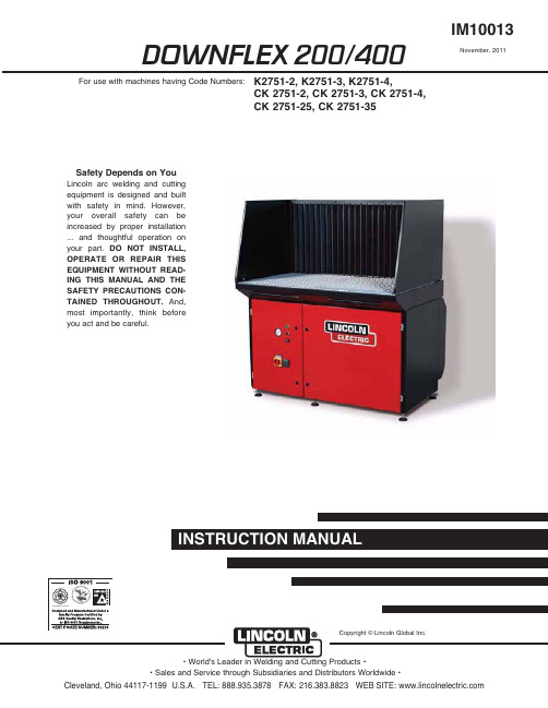
DOWNFLEX 200/400IM100131RYHPEHU , 2011Safety Depends on YouLincoln arc welding and cutting equipment is designed and built with safety in mind. H owever,your overall safety can be increased by proper installation ... and thoughtful operation on your part.DO NOT INSTALL,OPERATE OR REPAIR THIS EQUIPMENT WITHOUT READ-ING THIS MANUAL AND THE SAFETY PRECAUTIONS CON-TAINED THROUGHOUT.And,most importantly, think beforeyou act and be careful.For use with machines having Code Numbers:K2751-2, K2751-3, K2751-4,CK 2751-2, CK 2751-3, CK 2751-4,CK 2751-25, CK 2751-35Copyright © Lincoln Global Inc.vfor selecting a QUALITY product by Lincoln Electric. We want you to take pride in operating this Lincoln Electric Company product •••as much pride as we have in bringing this product to you!TECHNICAL SPECIFICATIONS - DOWNFLEX 200/400GENERAL DESCRIPTIONThe downdraft table is a workbench with an integrated extraction fan and filtration system that is used for welding, grinding and plasma cutting applications. Depending on the specific application, the use of cer-tain accessories is required and/or recommended. See Accessories section of this manual.The downdraft table features a work grid, a three-stage prefiltration system for optimum spark arresting and two oval main filter cartridges. Both pre and main filters have dust drawers underneath. The working height of the downdraft table is adjustable. The control panel contains a 120V power outlet for connection of any device, such as a vacuum cleaner or grinding machine (max. 1200W).INTENDED USEThe product has been designed as a workbench with integrated extraction and filtration facility for welding and grinding purposes, provided the appropriate options have been installed (See Accessories Section of this manual). Using the product for other purposes is considered contrary to its intended use. The manufacturer accepts no liability for any damage or injury resulting from such use. The product has been built in accordance with state-of-the-art standards and recognized safety regulations. Only use this product when in technically perfect condition in accordance with its intended use and the instructions explained in the user manual.COMPONENTSThe downdraft table consists of the following main components See Figures A.1 and A.2:A. Backdraft kitB. Side panels (left + right)C. Work grid (two-piece)D. Control panelE. Left door (controls/fan)F. Power outletG. Right door (filter compartment)H. Compressed air tank (DownFlex 400-MS andDownFlex 400-MS/A only)I. Prefilters (1st stage)J. Dust drawers (prefiltration)K. Dust drawer (main filter cartridges)L. Filter cleaning mechanism (DownFlex 400-MS and DownFlex 400-MS/A only)M. Filter cartridges (2)N. Prefilters (2nd stage)CFGDEBAORQ PIN MJKLINSTALLATIONTOOLS AND REQUIREMENTSThe following tools and requirements are needed to install the product:• Spanner M6 and M8• Hexagon wrench 10 and 13 ( in.)UNPACKINGCheck that the product is complete. The package should contain:• Downdraft table • Work grid (two-piece)• Cover strip with 8 bolts M6 (cover strip not included when backdraft kit and side panels are standard equipment; bolts packed with backdraft kit)• Square key 8 mm (to lock/unlock doors)• Square key 6 mm (to lock/unlock dust drawers and doors of electrics)If parts are missing or damaged, contact your supplier.OPTIONSMount optional side panels, back panel, backdraft kit,and/or plasma cutting work grid, if any. Otherwise,refer to Work Grid for mounting of work grid.SIDE PANELSSide panels are to be mounted to the back panel or backdraft kit. See Figure A.3.To mount the side panels, proceed as follows.1. Unscrew the bolts on the loose side of the hinges and remove the washers; keep the bolts and wash-ers.2. Put the pins through the holes on the sides of the back panel or backdraft panel.3. Place the washers and bolts over the pins.4. Tighten the bolts.FIGURE A.3 –SIDE PANELSABPLASMA CUTTING WORK GRIDThe plasma cutting work grid consists of:• 2 Grid frames 28.9 x 26.3 x 2.5 in. (735 x 669 x 64mm)• 2 x 13 Metal bars 28.54 x 2.36 x 0.16 in. (725 x 60 x 4 mm)A CB ABC (x 26)3. Unlock the H EPA filter cartridge by pressing a screwdriver or other tool at the position of the strips (B) on the top and bottom of unit. See Figure A.8.4. Take out the filter cartridge.5. Mount the adjustable feet underneath the HEPA kit.NOTE:Remove the outlet panel from the HEPA kit, aswell as the outlet grid inside the downdraft table, to facilitate mounting. Donʼt forget to replace them when mounting is complete.6. Place bolts halfway through the 2 upper holes (C) at the outlet of the downdraft table. See Figure A.8.7. Hang the HEPA box on the bolts.8. Place bolts through the 2 lower holes (D) in the HEPA box. See Figure A.8.9. Fasten the H EPA box by tightening the 4 bolts (C+D). See Figure A.8.10. Replace the filter cartridge.11. Lock the filter cartridge by pulling the two strapstightly. This is indicated by a “click” sound.NOTE:If a Silencer/Outlet duct has to be installed aswell, the outlet panel of the HEPA kit does not need to be mounted.12. Adjust the feet when the downdraft table is placedin place in its final position.NOTE:The outlet panel of the downdraft table is notused.SILENCER/OUTLET DUCT The Silencer/Outlet duct consists of:B(2x)AC(x2)D(x2)B AC (x2)DE(x4)A (x 6)B (x 3)A (x 2)B (x 3)-r e a r--r e a r-FIGURE A.11 –CONNECTIONSCA BThe wheel kit consists of:• 2 Swivel casters with brakes• 3 Swivel casters without brakesTo mount the wheel kit, proceed as follows.1. Carefully lift the downdraft table using a fork-lifttruck or pallet jack.2. Unscrew the 5 adjustable feet.3. Mount the swivel casters; mount the ones withbrakes at the left and right front corners.NOTE:Drive in the screw thread of the swivel casters as deep as possible.NOTE:By the use of the wheel set, the working height of the downdraft table is fixed to 37.4 in. (950mm).COMPRESSED AIR CONNECTION (DownFlex 400-MS and DownFlex 400-MS/A only) The downdraft table functions on compressed air with a recommended working pressure of 72-115 psi (5-8 bar). Always make sure that the working pressure is between these values (preferably at 72 psi/5 bar). If required, mount a pressure reducing valve to prevent overpressure. If the pressure is too high, the safety valve of the system will be opened, thus decreasing the pressure until the system pressure has reached an appropriate level.1. Connect the downdraft table to compressed air.See Figure A.11, item C. Connection ⅜in. POSITIONINGThe downdraft table can be positioned using:• A fork-lift truck (preferred way); or• A pallet jack (downdraft table has to be tilted); or • Cargo lashings lifted by a fork-lift truck. See FigureA.14.AA ABYELLOWcomYELLOWcomBAinjury. After switching off the fan,wait at least 20 seconds beforeopening the door(s) to carry out ser-vice, maintenance or repair jobs.• Industrial vacuum cleaner used during service and maintenance should meet OSHA guidelines for Cr6 housekeeping.• Always use the downdraft table with prefilters, filter cartridges and dust drawers properly installed.------------------------------------------------------------------------CAUTIONFILTER REPLACEMENT1. During use, regularly check the Magnehelic gauge(B). When the pressure reaches 0.25 psi (1700Pa), the filter cartridges need to be replaced. See Figure B.2.2. Refer to Filter Replacement for the filter replace-ment procedure.FILTER CLEANING1. During use, regularly check the Magnehelic gauge(B). When the pressure reaches 0.22 psi (1500Pa), the filter cartridges need to be cleaned. See Figure B.3.Filter cleaning procedure:The filter cleaning procedure takes place online.1. Make sure the downdraft table is switched on.2. Press button FILTER CLEANING (D) for 5 secondsto activate the filter cleaning system. See FigureB.3.The filter cleaning procedure takes 2 minutes, during which each filter cartridge is cleaned by 7 compressed air pulses.NOTE:To secure optimum filter efficiency, do not acti-vate the filter cleaning system within the first 20hours of operation or within 20 hours after filterreplacement.1. Check the pressure on the Magnehelic gauge (B). Ifthe pressure still exceeds 0.22 psi (1500 Pa), repeat the filter cleaning procedure (max. 5 times).See Figure B.3.FILTER REPLACEMENTIf the filter cleaning system is unable to get the pres-sure below 0.22 psi (1500 Pa) after 5 attempts, the fil-ter cartridges are probably saturated and need to be replaced.1. Push the ON/OFF button (C) to switch off the fan.See Figure B.3.2. Wait 20 seconds for fan to stop rotating.3. Turn switch (A) off to remove the main input power.4. Refer to Filter Replacement for the filter replace-ment procedure.AUTOMATIC FILTER CLEANINGEach time the downdraft table is switched off, the filter cartridges are automatically cleaned by a full cleaning cycle. This procedure takes approximately 7 minutes, during which each filter cartridge is cleaned by max. 10 compressed air blasts.NOTE:To secure optimum filter efficiency the filter cleaning system will not be activated during thefirst 20 hours of operation or within 20 hoursafter filter replacement.MANUAL FILTER CLEANINGIf desired, the filter cleaning system can be activated manually (online cleaning only).1. Push the ON/OFF button (C) to switch on the fan.See Figure B.4.2. Press button RESET ALARM/MANUAL CLEANING(D) during 5 seconds to activate the filter cleaningsystem. See Figure B.4.This procedure takes approximately 4 minutes, during which each filter cartridge is cleaned by 6 compressed air blasts.NOTE:To secure optimum filter efficiency the filter cleaning system cannot be activated during thefirst 20 hours of operation or within 20 hoursafter filter replacement.BUZZERThe buzzer may emit two different interrupted sounds:• 2 Seconds on - 2 seconds off: clogged filter• 2 Seconds on - 5 seconds off: compressed air miss-ingWhen the pressure over the filter cartridges reaches 0.22 psi (1500 Pa) during use, the buzzer will emit an interrupted sound (2 seconds on - 2 seconds off). In this case proceed as follows.1. Press button RESET ALARM/MANUAL CLEANING(D) to deactivate the buzzer. See Figure B.4.2. Push the ON/OFF button (C) to switch off the fan.See Figure B.4.After the fan has been switched off, the automatic filter cleaning procedure will be activated. See Automatic Filter Cleaning.NOTE:Buzzer sound is suppressed during one hour enabling the user to finish his job. If neces-sary/desired, buzzer can be suppressed(repeatedly), provided that the downdraft tableis switched off by ON/OFF button at the end ofthe day.NOTE:When welding/grinding and cleaning is finished turn switch (A) off to remove the main inputpower.FILTER REPLACEMENTWhen the filter cleaning system is unable to get the pressure below 0.22 psi (1500 Pa) after 5 attempts, the filter cartridges are probably saturated and need to be replaced. This is indicated by the buzzer emitting an interrupted sound (2 seconds on - 2 seconds off).1. Press button RESET ALARM/MANUAL CLEANING(D) to deactivate the buzzer (E). See Figure B.4.2. Push the ON/OFF button (C) to switch off the fan.See Figure B.4.3. Wait 20 seconds for fan to stop rotating.4. Refer to Filter Replacement for the filter replace-ment procedure.B E FH IL (x 5)C (x 2)This Troubleshooting Guide is provided to help you locate and repair possible machine malfunctions.Simply follow the three-step procedure listed below.Step 1.LOCATE PROBLEM (SYMPTOM).Look under the column labeled “PROBLEM (SYMP-TOMS)”. This column describes possible symptoms that the machine may exhibit. Find the listing that best describes the symptom that the machine is exhibiting. Step 2.POSSIBLE CAUSE.The second column labeled “POSSIBLE CAUSE” lists the obvious external possibilities that may contribute to the machine symptom.Step 3.RECOMMENDED COURSE OF ACTIONThis column provides a course of action for the Possible Cause, generally it states to contact your local Lincoln Authorized Field Service Facility.If you do not understand or are unable to perform the Recommended Course of Action safely, contact your local Lincoln Authorized Field Service Facility.HOW TO USE TROUBLESHOOTING GUIDEService and Repair should only be performed by Lincoln Electric Factory Trained Personnel.Unauthorized repairs performed on this equipment may result in danger to the technician and machine operator and will invalidate your factory warranty. For your safety and to avoid Electrical Shock, please observe all safety notes and precautions detailed throughout this manual.__________________________________________________________________________* Text printed in Bold refers to options and accessories.* Text printed in Bold refers to options and accessories.JapaneseChineseKoreanArabicREAD AND UNDERSTAND THE MANUFACTURERʼS INSTRUCTION FOR THIS EQUIPMENT AND THE CONSUMABLES TO BE USED AND FOLLOW YOUR EMPLOYERʼS SAFETY PRACTICES.SE RECOMIENDA LEER Y ENTENDER LAS INSTRUCCIONES DEL FABRICANTE PARA EL USO DE ESTE EQUIPO Y LOS CONSUMIBLES QUE VA A UTILIZAR, SIGA LAS MEDIDAS DE SEGURIDAD DE SU SUPERVISOR.LISEZ ET COMPRENEZ LES INSTRUCTIONS DU FABRICANT EN CE QUI REGARDE CET EQUIPMENT ET LES PRODUITS A ETRE EMPLOYES ET SUIVEZ LES PROCEDURES DE SECURITE DE VOTRE EMPLOYEUR.LESEN SIE UND BEFOLGEN SIE DIE BETRIEBSANLEITUNG DER ANLAGE UND DEN ELEKTRO-DENEINSATZ DES HERSTELLERS. DIE UNFALLVERHÜTUNGSVORSCHRIFTEN DES ARBEITGEBERS SIND EBENFALLS ZU BEACHTEN.JapaneseChineseKoreanArabicLEIA E COMPREENDA AS INSTRUÇÕES DO FABRICANTE PARA ESTE EQUIPAMENTO E AS PARTES DE USO, E SIGA AS PRÁTICAS DE SEGURANÇA DO EMPREGADOR.。
ZT40JE-V操作手册

ZT40JE-V操作手册对于其他种类的升降机而言,高空作业平台车是一种高风险的产品,就产品本身的安全性来说,需要科学技术、生产工艺和严格的生产管理来保证。
在使用的过程中,“人-机-环境”是高空作业安全中的重要环节,安全是保障高空作业平台施工的一个基础条件。
下面就是直臂系列高空作业平台车在使用过程中需要注意的事项:1、从事高处作业的人员必须身体健康。
患有精神病、癫痫病及经医师鉴定患有高血压、心脏病等不宜从事高空作业疾病的人员,不得参加高空作业。
若工作人员有饮酒、精神不振时,禁止登高作业。
2、进行高处作业前须搭建脚手架或采取其他防止坠落的措施,安装完之后方可进行作业。
3、在没有脚手架或者是在没有栏杆的脚手架上高空作业,高度超过1.5m时,必须使用安全带或采取其他可靠的安全措施。
4、在坝顶、陡坡、屋顶、悬崖、杆塔、吊桥以及其他危险的边沿进行高空作业时,临空一面应装设安全网或防护栏杆,否则,工作人员须使用安全带。
5、安全带的挂钩或绳子应挂在结实牢固的构件上,或专门为挂安全带设置的钢丝绳上。
高空作业时禁止挂钩挂在移动或不牢固的物件上。
6、安全带在使用前应进行检查,并应定期(每隔6个月)进行静荷重试验;试验荷重为225千克,试验时间为5分钟,试验后要检查安全带是否有变形、破裂等情况,并做好试验记录。
不合格的安全带应及时处理。
7、高空作业应一致使用工具袋,较大的工具应用绳拴在牢固的构件上,不得随意乱放,以防止发生高空坠落事故。
8、高空作业时不准将工具及材料上下投掷,要用绳系牢后往下或往上吊送,以免打伤下方工作人员或击毁脚手架。
9、在进行高空作业时,除有关人员外,不准他人在高空作业平台车附近通行或逗留,工作地点下面应有围栏或装设其他保护装置,防止物体落下伤人。
如在格栅式的平台上工作,为了防止工具和器材掉落,应铺设木板。
10、禁止登在不坚固的结构上(如石棉瓦屋顶)进行高空作业工作。
为了防止误登,应在这种结构的必要地点挂上警告牌。
NTC-400 Series Router 快速入门指南说明书

NTC-400 Series Router| I n d u s t r i a l I o T2This quick start guide is designed to get you up and running quickly and familiarise you with the NTC-400 Series router. More advanced set up instructions are provided in the user guide which can be downloaded from/product/m2m/ntc-400| I n d u s t r i a l I o T 3NTC-400 Series RouterPackage contentsThe NTC-400 Series package includes:1 x NTC-400 Series Router2 x Wall mountingbrackets1 x Quick Start Guide2 x 2.4GHz / 5GHz WiFi antennas 4 x Wall mountingbracket screws1 x 8-pin Terminal blockPre-requisitesTo complete the installation, you may require certain items such as screwdrivers and fasteners.2 x Cellular antennas| I n d u s t r i a l I o T4| I n d u s t r i a l I o T 5NTC-400 Series Router| I n d u s t r i a l I o T 6| I n d u s t r i a l I o T 7NTC-400 Series RouterConfiguring the routerThe web interface can be accessed via WiFi or Ethernet.Connecting via WiFi1. Connect and power up the NTC-400 Series router.2. On your client device (e.g. laptop, tablet), connect to the SSID labelled“NetComm_2.4GHz_XXXX” or “NetComm_5GHz_XXXX” where “XXXX” is four randomly generated digits. The unique SSID and password for the wireless networks are printed on the back cover of this Quick Start Guide and on the label affixed to the bottom of the device. Enter the WiFi password and then continue to the “Accessing the web interface” section.Connecting via Ethernet cable1. Connect and power up the NTC-400 Series router.2. Connect a standard straight-through Ethernet cable to your client PC and the other end to any of the LAN ports on the back of the NTC-400 Series router. Continue to the “Accessing the web interface” section.Accessing the web interface3. In a web browser on your client device, navigate to http://192.168.20.14. Enter the username and password printed on both the back cover of this Quick Start Guide and on the label affixed to the bottom of the device, then press Enter or the click the Login button. Refer to the User Guide for further configuration instructions.NOTE: We highly recommend that you secure the WiFi networks upon initial installation and change the password used to access the web interface.| I n d u s t r i a l I o T 8Unlocking the SIM cardIf the inserted SIM card is PIN locked, navigate to Basic Network >WAN & Uplink > WAN Interface IPv4 Network Status > WAN-1 > Edit > Internet Setup > WAN-1 > Edit > Connection with SIM-A / SIM B card > PIN Code to enter the PIN Code. Click the Savebutton to save your changes.NOTE: SIM B is disabled on units purchased through Telstra. On these units, configure the SIM card in slot A.| I n d u s t r i a l I o T 9NTC-400 Series RouterUpdating the APNThe default connection profiles for both SIM-A and SIM-B are configured for automatic configuration. If you wish to configure the APN manually, navigate to Basic Network > WAN & Uplink > WAN Interface IPv4 Network Status > WAN-1 > Edit > Internet Setup > WAN-1 > Edit > Connection with SIM-A / SIM B card , set Dial-Up Profile to “Manual-configuration” and enter the APN into the APN field. Click the Savebutton to save your changes.NOTE: SIM B is disabled on units purchased through Telstra. On these units, configure the SIM card in slot A.| I n d u s t r i a l I o T 10Verifying the connection statusWhen the NTC-400 Series router is connected to the Internet, the “HIGH” or “LOW”LED on the front of the device lights up to indicate the current signal strength.To check the connection status from the web interface, navigate to Status > Dashboard and confirm that there is a 3G/4G Interface displayed under the Network Interface Status table.| I n d u s t r i a l I o T11NTC-400 Series RouterProduct WarrantyFor warranty information please visithttps:///warranty-info Safety and product carePlease refer to the user guide for safety and product care information.NETCOMM WIRELESS LIMITED ABN 85 002 490 486Head Office , 18-20 Orion Road Lane Cove, Sydney, NSW 2066, Australia p: +61 2 8205 3888 f: +61 2 9424 2010e:**************************** Q S G -00108 r e v 13。
RKC CH402 中文操作手册

感謝您購買本系列溫控器,請事先詳細閱讀此“使用說明書”,本說明書中的資料如改動恕不通知,敬請諒解。
本溫控器的製造經過嚴格地品質管理,如遇有不正常的狀態或顯示,請即刻與北京四通股份公司工控部或您的供應商聯絡。
第1章準備篇 1.型號定義┄┄┄┄┄┄┄┄┄┄┄┄┄┄┄┄┄1-12.安裝┄┄┄┄┄┄┄┄┄┄┄┄┄┄┄┄┄1-22.1外形尺寸2.2安裝方法3.接線3.1端子構成3.2接線注意事項4.規格4.1輸入4.2設定4.3顯示4.4輸出第2章功能篇 1.控制1.1PID控制1.2加熱、冷卻控制1.3正動作、逆動作1.4自動演算(AT)功能1.5自主校正(ST)功能1.6設定資料鎖(LCK)功能2.報警2.1溫度報警2.2加熱器斷線報警(HBA)2.3控制環斷線報警(LBA)3.輸入異常時的動作第3章操作篇 1.設定前狀態2 S V設定模式3.參數設定模式4工程師參數設定模式第4篇通訊篇(僅限CD系列表)第5篇其它第1篇準備篇1.型號定義請參照下列代碼表確認產品是否與您指定的型號一致。
CD/CH □01/02□□□-□□*□□-□□①②③④⑤⑥⑦⑧⑨⑩①規格尺寸詳見第1篇2.1節②控制類型F:PID動作及自動演算(逆動作)D:PID動作及自動演算(正動作)W:加熱/冷卻PID動作及自動演算(水冷)*1A:加熱/冷卻PID動作及自動演算(風冷)*1③輸入類型:見輸入範圍表④範圍代碼:見輸入範圍表⑤第一控制輸出(OUT1)(加熱側)M:繼電器接點輸出8:電流輸出(DC4~20mA)V:電壓脈衝輸出G:閘流控制管驅動用觸發器輸出T:閘流控制管輸出⑥第二控制輸出(OUT2)(製冷側)*2無記號:當控制動作是F或D時M:繼電器接點輸出T:閘流控制管輸出V:電壓脈衝輸出8:電流輸出(DC4~20mA)⑦第一報警(ALM1),⑧第二報警(ALM2)*2N;未設報警J:下限輸入值報警A:上限偏差報警K:附待機上限輸入值報警B:下限偏差報警L:附待機下限輸入值報警C:上、下限偏差報警P:加熱器斷線報警(CTL-6)*3 D:範圍內報警S:加熱器斷線報警(CTL-12)*3 E:附待機上限偏差報警R:控制環斷線報警*4F:附待機下限偏差報警V:上限設定值報警G;附待機上下限偏差報警W:下限設定值報警H:上限輸入值報警⑨通信功能(僅限CD系列)N:無通信功能5:RS-485(雙線系統)⑩防水/防塵功能N:無防水/防塵功能1:有防水/防塵功能注:*1W或A型無自主校正功能*2第二控制輸出(OUT2)﹑第二報警(ALM2)為選項*3不能被定為第一報警(ALM1)*4控制環斷線報警只能在第一報警和第二報警中選擇其一2.安裝2.1外形尺寸2.2安裝方法⑴按照盤面開孔尺寸在盤面上打出用來安裝儀器的矩形孔。
VR-MSI450和VR-MSI400多速旋转机操作说明书

4)MULTISPEED Control Dial:The VR-MSI450 and VR-MSI400 multispeed rotary machines have 3 speed settings,each speed setting (used with the correct pad) is suited to a different cleaning application. When setting the speed it is recommended that the following guidelines are used 200 RPM – Scrubbing, Carpet Cleaning, Stripping. 400 RPM – Spray Cleaning 600 RPM – BurnishingTo select the required speed, rotate the speed selector knob until it points at the appropriate RPM.NOTE:To protect the motor from overload, the machine has a built in safety feature that will slow the motor down if the machine is being used for an application that it is not designed for. If this occurs, check that the speed setting, pad type and condition are suitable for the application that the machine is being used for.CAUTION:Operating the machine at either an incorrect speed for an application or theincorrect pad type can result in damage to floor covering.ROUTINE MAINTENANCEAlways remove plug from socket outlet before carrying out any routine maintenance.1)Wipe all surfaces of the machine after use, particularly after scrubbing or spray cleaning.2) Always wind the cable around the bottom cable hook and the handle.3) Wipe power cable clean after use, using a cloth. Check cable visually for signs of wear and damage. If any is detected, ensure that it is replaced immediately.This operation need not require a service call, as a new cable can be plugged in by unqualified Personnel.4) (Lynx Models) It is important that the dust collection bag is changed regularly.5)(Exhauster Models) Change dust bag when bag full indicator light comes on.6)(Lynx / Excel Models) The seal on the skirt can be removed and refitted the other way around to double the life.1. Safety Switch2. Power On Light3. On/Off Lever4. Height Adjustment Control5. Solution Dispenser C ontrol / Bottle6. Inlet Socket7. Exhauster On/Off Switch 8. Exhauster9. Bag Full Indicator Light 10. Socket Box11. Cable Inlet Moulding12. Dust Bag Cover (Lynx models)OPERATING INSTRUCTIONS1)Attach drive board and pad:• Tilt the machine back on its wheels until the machine is resting on the floor exposing the drive mechanism.• The brush or drive board should now be placed on the drive mechanism and locked in place by turning the brush or board anti clockwise.• If a drive board is used, you must select the appropriate size and grade of pad and fit to the drive board.• With the brush or drive board fitted, the machine can be returned to the upright position.• Reverse process to remove brush or drive board.Attach drive pad (LYNX / EXCEL Models):• Tilt the machine back on its wheels until the machine is resting on the floor exposing the drive mechanism.• Unscrew the central pad retainer by pushing it inwards and rotating it anti- clockwise.• Select grade and size of pad: Excel 16 = 16” pad, Lynx 17 = 17” pad, Lynx /Excel 20 = 20” pad.•Screw the central pad retainer clockwise through the pad and into the threaded location in the drive mechanism. The pad retainer should click when fully tightened .2)Operate the machine: (See graphic)• Plug into power supply and check that the green power on light is on. (fig 2)• The handle should be adjusted to a comfortable working height, when the pad or brush is flat on the floor.• The handle is adjusted by pulling the height adjustment lever (fig 4). This allows the handle to be adjusted. The handle will lock into position when this lever is released.EXCEL Models: Once lock is released, the handle is ‘free floating’ enabling the operator to work at a preferred handle height.• Lift the handle so that the machine base is parallel to the floor.•Operate the machine by sliding one of the safety switches (fig 1) outwards and lifting the corresponding on/off lever (fig 3). Once in operation, the safety switch can be released.•To start vacuum option, ensure exhauster power cable is connected to the inlet socket (fig 6), press switch located at the top of the exhauster unit (fig 7) to the on position.• A pply solution by lifting solution dispenser lever (fig 5 ). (If Applicable)3)Control machine movement:• When the brush or pad is flat on the floor, the machine will stay in the central position.• To move to the Right – slightly Raise the handle.•To move to the Left – slightly Lower the handle.Control machine movement (LYNX / EXCEL Models):• The machine is operated in a forward motion, do not use the machine in astationary position.High Visibility Cable Pack Replacement :1)Disconnect machine from mains supply.2) Unscrew 2 x 4mm screws (fig 11) that attach the cable inlet moulding to the socket box.3) Disconnect the straight connector (attached to the cable) from the inlet socket (attached to the socket box).4) To connect new Victor cable pack (Part No D1000), reverse the process.NOTE: In the interests of operator safety and to prevent the use of inferior replacement cables,VICTOR machines are fitted with Anti-Tamper(screw),High Visibility cable packs comprising of Cable Inlet Moulding, Straight Connector, High Visibility Cable and Moulded Plug. Replacement packs (Part No:D1000) are available from Victor direct or their agents.SAFETY INFORMATIONa) This machine should only be used by trained operators.b ) Do not use this machine unless it is in a safe condition. Check the cable and plug for damage before use, and if necessary, replace with a new cable pack.c)To stop the machine, release the on/off switches whilst holding on to the handle.d)Always pay attention to the cable and keep it away from the brush, drive board and pad. Hazard may occur if machine runs over power supply cord.e) Always work within the cable length to avoid cable stress or damage.f) When using a solution tank, always empty the tank after use into a safe,suitable, approved location.g) Never use dirty pads or allow pads to become over soiled before changing.h) This machine has been designed for use with the boards supplied by themanufacturer. The fitting of other Boards may effect its safety. For a guide to different Board types and their intended use, refer to the VICTOR Rotary Floor Machines brochure, available on request.i) Check that the voltage shown on the serial number plate is suitable for thesupply available.j) Only use the outlet socket for its intended purpose.(Exhauster Attachment)k) Machine ingress rating : IPX4l) The VICTOR Rotary Floor Machines maximum A-Weighted sound pressurelevel Lpa measured in dB(A) is less than 85dB(A).m) The maximum r.m.s. acceleration value of a VICTOR Rotary Floor Machinewhich operators arms are subjected to =1.5m/s².n) Always remove plug from mains socket outlet before carrying out anycleaning, routine maintenance, drive board or pad attachment.O) Always remove Drive Board or Brush from machine when not in use.CIRCUIT BREAKER (except Multispeed)If the machine is overloaded, the circuit breaker will trip out. The reset button can be depressed after 30 seconds to restart the machine.NOTE: BEFORE RE-SETTING CHECK:-1) The pad, if a drive board is used , is clean. (if not, turn or change)2)There are no cable or supply faults.© Dowding & Plummer Ltd. Issue Level 4, Mar 2010For an exploded parts listing for thismachine visit our web site:8971210116123534SAFETY INFORMATION (Cont’d)WARNING THIS APPLIANCE MUST BE EARTHED IMPORTANT:Wires in the mains lead are coloured in accordance with the following code:Green and Yellow = Earth (This is connected to terminal E)Blue = Neutral (This is connected to terminal N)Brown = Live (This is connected to terminal L)VICTOR STANDARD WARRANTY CONDITIONSWith the exception of Distributors, this warranty applies to the original purchaser of the product from Dowding & Plummer Ltd.,(The Company) for the following periods:Vacuum Cleaners – Motors 2 Years, all other components 1 YearRotary Floor Machines – Motors 2 Years, all other components 1 YearScrubber Driers – Control Unit and Tanks 2 Years, all other components 1 YearCarpet Extractors – 1YearBattery Burnishers – 1YearSpecialist Machines – 1 YearThis warranty excludes normal maintenance parts and consumables such as hoses, filters, drive belts, floor tools, cables, capacitors, relays, skirts and pads etc. that are considered replaceable during the normal working life of the machine. This list is not exhaustive.The warranty period commences from the date the goods are purchased by the user.All warranty claims must be processed through the Distributor from whom the equipment was purchased.The Distributor will be responsible for the service, maintenance and repairs during the warranty period.The Distributor will co-operate with the purchaser throughout the warranty claims procedure and will arrange any necessary repairs using genuine Victor parts.If the original Distributor is no longer available to fulfil his obligations, or if you did not make your original purchase through a distributor, the Company should be contacted and given details of proof of purchase and full details of the claim in order that the claim may be processed without delay.Any warranty claim can only relate to the specific part that is proven to be at fault and for which a replacement will be supplied but cannot be extended to constitute a claim against the complete appliance.The Company will supply the Distributor with any warranty parts required subject to the claim being validated after return of the faulty items in accordance with the Company's Conditions of Sale.All replacement parts are guaranteed for a period of 6 months.Claims will not be accepted if they are the result of fair wear and tear, misuse or abuse of any kind, acts of God, damage in transit other than original product delivery, failure due to lack of proper care or maintenance or failure to comply with safety guidance.No replacement will be given unless the appropriate evidence of the validity of the claim has been provided to the satisfaction of the Company.The Company reserves the right to charge for any unnecessary work carried out as a result of an invalid claim.No variation to this warranty may be made or implied by any member of the Company, its Distributors or representatives unless such variation is in writing and authorised by the Company.EXTENDED WARRANTIESExtended warranty packages are available on all our rotaries, please contact Dowding & Plummer Ltd Service Department for details.WEEE DIRECTIVEProducts bearing this symbol should not be disposed of in your general waste.Dowding & Plummer Ltd is a registered producer under the WEEE Directive -(number WEEE/AB0043SY/PRO) and has procedures in place for dealing withthe end of life treatment & disposal of obligated equipment. Please contact theCompany or visit our website for more details.Pro RangeLynx RangeEuropa RangeHeavy Duty TrojanSprite 300INSTRUCTION。
Lettuce King 400N, 401N, 402NC, 403N, 4400N 操作手册说明

Item No. 2350026-1 en Rev 07/14ENGLISHLettuce King ®I400N, 401N, 402NC, 403NLettuce King ® IV4400NThank you for purchasing this Vollrath Food Processing Equipment. Before operating the equipment, read and familiarize yourself with the following operating and safety instructions. SAVE THESE INSTRUCTIONS FOR FUTURE REFERENCE. Save the original box andpackaging. Use this packaging to ship the equipment if repairs are needed.R egisteR youR pRoduct on -line at www .V ollRath .comDrum Ring shown sold separately.O peratOr ’s Manual2E N G L I S HS afety P recautionSTo ensure safe operation, read the following statements and understand their meaning. This manual contains safety precautions which areexplained below. Please read carefully.WARNINGWarning is used to indicate the presence of a hazard that can cause severe personal injury, death, or substantial property damage if thewarning is ignored.CAUTIONCaution is used to indicate the presence of a hazard that will or can cause minor personal injury or property damage if the caution is ignored.NOTENote is used to notify people of installation, operation, or maintenance information that is important but not hazard-related.For Your Safety!These precautions should be followed at all times. Failure to follow these precautions could result in injury to yourself and others or damage the equipment.Check equipment before each use to insure the equipment is clean. Check for broken, nicked or dull blades and if found, replace the bladeassembly.Check to insure that the pusher head sits down completely on the rubberbumpers.If necessary, lubricate guide rods using a light coating of mineral oil, PetroGel, or food grade lubricant. DO NOT USE COOKING OIL AS IT WILL BECOME STICKY AND MAY PERMANENTLY DAMAGE THE PUSHER HEAD BEARINGSf unction and P urPoSeIntended for cutting, dicing and wedging vegetables and fruits.f eatureS and c ontrolSGDBHCEE Figure 1. Features and Controls Lettuce King I.A AHE E G J J D KCCIIBFigure 2. Features and Controls Lettuce King IV.3ENGLISHO peratOr ’s ManualLEGS. Supports the equipment.pusher head block (and the handle for tabletop models).in the up position.match the corresponding pusher head block.equipment.the handle assembly to the base. Secures the safety lock to thebase.the up position.u nPacking the e quiPment and i nitial S etuPCarefully remove crating or packaging materials from the equipment. Dispose of all packaging ,materials in an environmentally responsible manner. Leg installation Lettuce King I:1. Use the screws (A) and washers (B) to install legs (C) tightening withwrench (D). See Figure 3.Leg installation Lettuce King IV:1. Use the capscrews (A) and rubber washers (B) to install legs (C). See Figure 5.Figure 5. Legs and Hardware for the Lettuce King IV.2. Set legs (C) into the holes in the base assembly (D) so the angled part of the leg faces outward. See Figure 5.3. Secure legs (C) to base assembly (D) using capscrews (A) and rubber washers (B). See Figure 5.4. Tighten capscrews (A) slowly and rotate the legs slightly so that the end of the capscrew (A) enters the notch (E) in the leg (C). See Figure5.O peratOr ’s Manual4E N G L I S H4. Do not wipe across the blades or use scrub pads on this equipment. Wiping across the sharp edge of the blade can cause injury and will dull the blades.5. The blade assembly (G) is best cleaned by forcing water under pressure through the blades from the unsharpened side. If necessary, use a nylon bristle cleaning brush to push food particles out from the unsharpened side of the blade assembly (G).6. Do not put this equipment in a dishwasher or dish machine with soaps, detergents, or other alkaline chemicals that can harm the equipment.7. After cleaning, let the equipment air dry.8. Lubricate the sliding parts with mineral oil or Petro Gel after each use. Do not use cooking oil as it will become sticky and may permanently damage the equipment.P reventative m aintenance1. Clean equipment after every use.2. Use for intended purposes only.3. Change blades regularly - based on usage.r ePlacing B lade a SSemBlySharp Blade Hazard.Blades are sharp and can cause cuts. To avoid injury from sharp blades, handle with caution.Wash new blades with warm, soapy water and rinse thoroughly to remove the thin protective oil film. Keep the sharp edge away from you when handling blades.Lettuce King I :1. Familiarize yourself with the parts diagram for your equipment.See Figure 6 (Spare Parts for Lettuce King I) for parts to reference for this procedure.2. Allow ample room to work on a flat, dry surface.3. Raise the handle and pusher head as far up as it will go.4. Verify that the pusher head bumpers (R) are installed. If missing, clean the surface and install new pusher head bumpers(s).5. Remove the screws retaining the blade assembly (T). Carefully remove and dispose the blade assembly.6. Examine the pusher head (J) fingers. If they are nicked or burred, smooth the rough edges with a small flat file. The spaces between the fingers must be uniform. Straighten any bent fingers.7. Verify that blade shields (U) are installed on the blade assembly (T).8. Place the blade assembly (T) into the base assembly (P) so the it is seated correctly and the sharp side up.9. Install the screws into the rear side of the blade assembly (T). Tighten until contact is made with the base assembly (P). Turn the screw until tight, do not exceed 1/2 turn or 40 in. lbs.10. Place rubber washer between the base assembly (P) and the bladeassembly (T). Insert the screws through the frame, and rubber washer into the blade assembly. Turn the screw until tight, do not exceed 1/2 turn or 40 in. lbs.o PerationSharp Blade Hazard.Blades are sharp and can cause cuts. To avoid injury from sharp blades, handle with caution.Prior to first use, it is important to clean the equipment. Wash new blades with warm soapy water and rinse thoroughly to remove the thin protective oil film. 1. Before each use, check that the equipment is clean and the blades are in good condition. If loose or broken blades are found, blades must be serviced.2. Before each use, always check for proper blade alignment. Slowly set the pusher head (D) onto the blade assembly. See Figures 1 and 2. They should slide together with no obstructions. If there are obstructions, verify they are a matching set.3. Verify that the blade assembly and pusher head assembly are the desired size.4. Prepare the food product to be processed.5. Lift the handle (B) and place the food on the blade assembly (G) with the flat side down. See Figures 1 and 2.6. Lettuce King I : Remove hand from the blade assembly (G) area and place that hand on the leg (C). See Figure 1.Lettuce King IV : Hold the handle (B), remove hand from the bladeassembly area and place that hand on the lock lever (F). Push lock lever (F) in to release the lock arm from the locked position. See Figure 2.Using a strong, quick, downward thrust, force the food product through the blade assembly.Repeat this process until you have prepared enough food product for your daily needs.9. Clean and lubricate your equipment immediately after each use. See the CLEANING section of this manual for more information.c leaningSharp Blade Hazard.Blades are sharp and can cause cuts. To avoid injury from sharp blades, handle with caution.To maintain the appearance and increase the service life, clean your daily. NOTE:Food acids will make blades dull and corrode the metal. Always clean this food preparation equipment immediately after every use.1. Raise the handle to put the highest position. See Figures 1 and2.2. Clean large excess pieces of scrap with the special brush provided with this equipment.3. Wipe, rinse or spray off equipment, pusher head and blade assembly thoroughly with HOT water.5ENGLISHO peratOr ’s M anualfingers. Tighten the locking collar set screws.12. Lubricate the pusher head pivot rod with mineral oil or Petro Gel after each use. Do not use cooking oil as it will become sticky and may permanently damage the equipment.Lettuce King IV :1. Familiarize yourself with the parts diagram for your equipment.See Figure 7 (Spare Parts for Lettuce King IV) for parts to reference for this procedure.2. Allow ample room to work on a flat, dry surface.3. Raise the handle and pusher head as far up as it will go.4. Remove the screws retaining the blade assemblies (CC) and (DD). Carefully remove and dispose the blade assemblies.5. Examine the pusher head (K). If they are nicked or burred, smooth the rough edges with a small flat file.6. Verify that blade shields (BB) are installed on the blade assembly (CC) and (DD).7. Place the lower blade assembly (CC) into the frame (H) so the it is positioned correctly and the sharp side up.t rouBleShootingIf the equipment no longer processes food cleanly or without damage to the food product, the blades could be dull and be in need of replacement. Broken, bent, or nicked blades must be replaced.9. Place rubber washer between the right side frame (H) and the blade assembly (CC). Insert the screws through the frame, and rubber washer into the blade assembly. Turn the screw until tight, do not exceed 1/2 turn or 40 in. lbs.10. Place the upper blade assembly (DD) into the frame (H) so the it is positioned correctly and the sharp side up.11. Install the screws into the front side of the blade assembly (DD). Tighten until contact is made with the frame (H). Turn the screw until tight, do not exceed 1/2 turn or 40 in. lbs.12. Place rubber washer between the back side frame (H) and the blade assembly (DD). Insert the screws through the frame, and rubber washer into the blade assembly. Turn the screw until tight, do not exceed 1/2 turn or 40 in. lbs.13. Slowly bring the pusher head down to the blades.14. Lubricate the main frame guide rods with mineral oil or Petro Gel after each use. Do not use cooking oil as it will become sticky and may permanently damage the equipment.O peratOr ’s Manual6E N G L I SHSPare PartS liSt - l ettuce k ing i7ENGLISHO peratOr ’s M anualABC DEFG HMNOPIJK LQ RSTUCIO peratOr ’s Manual8E N G L I S HSPare PartS liSt - l ettuce k ingiv9ENGLISHO peratOr ’s M anualABD E FG HIJKL M N OP Q RSTU VW XYZAANNVNBBBCCDDPFigure 7. Spare Parts for Lettuce King IV.CEE The Vollrath Company, L.L.C.1236 North 18th StreetSheboygan, WI 53081-3201U.S.A.Main Tel: 800.628.0830Fax: 800.752.5620Technical Services: 800.628.0832Service Fax: 920.459.5462Canada Service: 800.695.8560© 2014 The Vollrath Company, L.L.C.Item No. 2350026-1 en Rev 07/14S ervice and r ePairPlease contact Vollrath Technical Service from the list below.VOLLRATH Technical Service • 1-800-628-0832 (USA)•Email:******************************When contacting Vollrath Technical Service, please be ready with the item number, model number (if applicable), serial number, and proof of purchase showing the date the equipment was purchased.W arranty S tatement for t he v ollrath c o. l.l.c.This warranty does not apply to products purchased for personal, family or household use, and The Vollrath Company LLC does not offer a written warranty to purchasers for such uses.The Vollrath Company LLC warrants each of its products listed below against defects in materials and workmanship for the applicable period provided below. All other products manufactured or distributed by The Vollrath Company LLC are warranted against defects in materials and workmanship for a period of one year. In all cases, the warranty runs from the date of the end user’s original purchase found on the receipt. Any damages from improper use, abuse, modification or damage resulting from improper packaging during return shipment for warranty repair will not be covered under warranty.Vollrath – Redco® products – The warranty period is 2 years.Replacement parts – The warranty period is 90 days.No remedy for normal use wear and tear or other causes not arising from defective material or workmanship. These components may be warranted if manufactured defective or due to material defect.For complete warranty information, product registration and new product announcement, visit .。
- 1、下载文档前请自行甄别文档内容的完整性,平台不提供额外的编辑、内容补充、找答案等附加服务。
- 2、"仅部分预览"的文档,不可在线预览部分如存在完整性等问题,可反馈申请退款(可完整预览的文档不适用该条件!)。
- 3、如文档侵犯您的权益,请联系客服反馈,我们会尽快为您处理(人工客服工作时间:9:00-18:30)。
智能技术
COTAO 利用最新驱动、电子、传感和智能控制技术,结合条码、RFID、机器视觉等自动识别 技术,不断研发高性能的打印贴标产品,简化用户操作,提高生产效率,降低人力成本。
六.设备图纸.................................................................................................................................56 七. 贴标部件的安装调试.....................................................................................................57
三.标签碳带...................................................................................................................................9 3.1 选择标签...........................................................................................................................10 3.2 选择色带...........................................................................................................................11 3.3 安装标签碳带...................................................................................................................12 3.31 安装标签.................................................................................................................12 3.3.2 安装色带................................................................................................................19
五.打印机设置............................................................................................................................. 42 5.1 控制面板...........................................................................................................................42 5.2 打印参数设置...................................................................................................................42
7.1 贴标机构与打印机出口之间的位置调整...............................................................57 7.2 辅助吹气管角度调整...............................................................................................59 八.设备常见故障处理及维护 ..................................................................................................... 60 8.1 打印机故障处理...............................................................................................................60 8.2 其他故障处理...................................................................................................................60 8.3 设备维护保养...................................................................................................................62 8.3.1 所需工具................................................................................................................62 8.3.2 打印机保养............................................................................................................62 8.3.3 贴标机维护............................................................................................................67
COTAO® 科道 Intelligent Labeling System
目录
Z400 紧凑型打印贴标机..................................................................................................................1 公司简介...................................................................................................................................3 部分行业客户........................................................................................................................... 3 合作伙伴...................................................................................................................................4
COTAO® 科道 Intelligent Labeling System
Z400 紧凑型打印贴标机
公 司 名 称: 文 件 名 称: 版 本 号:道物流科技有限公司 Z400 自动打印贴标机使用手册 2.0
2014‐02‐10
版权所有© COTAO®科道 保留所有权利。 1
版权所有© COTAO®科道 保留所有权利。 2
COTAO® 科道 Intelligent Labeling System
公司简介
上海科道物流科技有限公司(注册商标:COTAO)成立于 2002 年,是中国最大最专业的打印 贴标机生产厂家。COTAO 提供全系列的打印贴标机、贴标机械手和打印贴标工作站的设计开发、 生产制造、软件集成、安装调试和维护服务,广泛应用于汽车、电子、医药、食品、饮料、物流 和电子商务等行业。
二. 设备结构....................................................................................................................................5 2.1 设备整体结构介绍.............................................................................................................5 2.2 设备参数.............................................................................................................................7 2.3.电源,气源,环境.......................................................................................................... 8 2.3.1 电源要求..................................................................................................................8 2.3.2 气源要求..................................................................................................................8 2.3.3 使用环境..................................................................................................................8