Patrol central安装手册
Copeland 监督控制平台安装和操作手册说明书

Supervisory Control PlatformInstallation and Operation ManualFW 2.26026-1803 R9Copeland | Electronics and Controls 1065 Big Shanty Road NW, Suite 100Kennesaw, GA 30144 USA 770-425-2724 • 1-800-829-2724 Email: ****************************************FIRMWARE VERSION2.26For release notes and other product information, click here .FCC COMPLIANCE NOTICEThis device complies with Part 15 of the FCC Rules Class A. Operation is subject to the following two conditions: (1) this device may not cause harmful interference, and (2) this device must accept any interference received, including interference that may cause undesired operation.CE COMPLIANCE NOTICEClass A Product Information for Supervisory Controller:The Supervisory Controller are Class A products. In a domestic environment this product may cause radio interference in which case the user may be required to take adequate measures.ULE211299ELECTROSTATIC DISCHARGE CAUTION This integrated circuit can be damaged by ESD. Failure to observe proper handling and installation procedures can cause damage. ESD damage can range from subtle performance degradation to complete device failure. Precision integrated circuits may be more susceptible to damage because very smallparametric changes may cause the device to not meet its published specifications.iii026-1803 R9Contents1 INTRODUCTION......................................................................................................................................................................... 1-11.1 S UPPORTED B ROWSERS ....................................................................................................................................................................... 1-11.2 D IRECT C ONNECT I NSTRUCTIONS - C ONNECT YOUR LAPTOP TO S UPERVISORY C ONTROLLER ’S E THERNET P ORT ETH 1....... 1-11.3 L OGGING I NTO THE S UPERVISORY C ONTROLLER .............................................................................................................................. 1-31.4 H OW TO C HANGE THE IP A DDRESS .................................................................................................................................................... 1-41.4.1 Method 1: Direct Connect..................................................................................................................................................... 1-41.4.2 Method 2: USB Port.................................................................................................................................................................. 1-41.5 S ETUP W IZARD ...................................................................................................................................................................................... 1-52 E3 HARDWARE OVERVIEW ................................................................................................................................................... 2-12.1 E3 O RDERING I NFORMATION ............................................................................................................................................................... 2-12.2 T ECHNICAL S PECIFICATIONS .............................................................................................................................................................. 2-22.3 P LUG -I N D IGITAL I/O C ARD (P/N 537-4880).................................................................................................................................. 2-22.3.1 LED’s............................................................................................................................................................................................. 2-22.4 W IRING ................................................................................................................................................................................................... 2-32.5 E THERNET C ONNECTIONS ................................................................................................................................................................... 2-32.6 E3 RS485 W IRING G UIDE E XAMPLE .................................................................................................................................................. 2-42.7 E3 W IRING D IAGRAMS ......................................................................................................................................................................... 2-73 SITE SUPERVISOR HARDWARE OVERVIEW...................................................................................................................... 3-13.1 O RDERING INFORMATION .................................................................................................................................................................... 3-13.2 T ECHNICAL S PECIFICATIONS ............................................................................................................................................................... 3-23.3 S ITE S UPERVISOR H OUSING D IMENSIONS AND M OUNTING .............................................................................................................. 3-33.4 W IRING D IAGRAMS ................................................................................................................................................................................ 3-43.5 D EVICE W IRING ..................................................................................................................................................................................... 3-53.6 S ITE S UPERVISOR P OWER , S ERIAL , AND IO P OSITIONS ..................................................................................................................... 3-53.6.1 Termination Jumpers.............................................................................................................................................................. 3-53.6.2 Using a DC Volt Meter to Check Termination and Bias................................................................................................ 3-63.6.3 Removing The SD Card.......................................................................................................................................................... 3-63.6.4 LEDs.............................................................................................................................................................................................. 3-63.6.5 Dip Switch Termination and Biasing.................................................................................................................................. 3-73.7 S ERIAL C ONNECTIONS ......................................................................................................................................................................... 3-83.8 W IRING T ERMINAL D ETAIL .................................................................................................................................................................. 3-83.9 D IGITAL I NPUTS .................................................................................................................................................................................... 3-93.10 R ELAY O UTPUTS ................................................................................................................................................................................ 3-93.11 A NALOG I NPUTS .............................................................................................................................................................................. 3-103.12 S ITE S UPERVISOR W IRING E XAMPLES ........................................................................................................................................... 3-104 SUPERVISORY CONTROLLER BASIC NAVIGATION........................................................................................................ 4-14.1 M ENUS AND S UBMENUS ....................................................................................................................................................................... 4-14.2 COM P ORT B ANDWIDTH C OLOR S CHEME ........................................................................................................................................ 4-24.3 COM P ORT B ANDWIDTH C ALCULATOR ............................................................................................................................................. 4-34.4 O VERVIEW .............................................................................................................................................................................................. 4-44.4.1 Conditional Visibility............................................................................................................................................................... 4-44.4.1.1 User View Details ...................................................................................................................................................................................... 4-44.5 B ASIC S CREEN E LEMENTS ................................................................................................................................................................... 4-54.6 L ANGUAGE S ETTINGS ........................................................................................................................................................................... 4-6User Manualiv 4.7 L OCATING AND W ORKING W ITH A PPLICATIONS ............................................................................................................................... 4-74.8 A PPLICATION T ABS .............................................................................................................................................................................. 4-74.8.1 Performance Meter.................................................................................................................................................................. 4-74.8.2 Site Aggregation....................................................................................................................................................................... 4-84.8.3 Control Inventory...................................................................................................................................................................... 4-84.8.3.1 Adding Applications................................................................................................................................................................................. 4-94.9 ADF S ..................................................................................................................................................................................................... 4-94.10 C REATING A B ACKUP AND R ESTORE ................................................................................................................................................ 4-94.10.2 Encrypted Backup.............................................................................................................................................................. 4-104.10.3 Restore.................................................................................................................................................................................... 4-104.11 U SING THE H ELP M ENU .................................................................................................................................................................. 4-114.12 I CONS OR B UTTONS A PPEARING ON THE H OME S CREEN ............................................................................................................ 4-125 LOGGING GROUPS.................................................................................................................................................................... 5-15.1 S UPPORTED F UNCTIONS ...................................................................................................................................................................... 5-15.2 D ATA L OGGING T YPES ......................................................................................................................................................................... 5-15.3 L OGGING G ROUP F UNCTIONS ............................................................................................................................................................. 5-16 ALARM CONFIGURATION....................................................................................................................................................... 6-16.1 A LARM C ONFIGURATION ..................................................................................................................................................................... 6-26.2 A LARM C OMMUNICATIONS ................................................................................................................................................................. 6-26.2.1 Alarm Communications Setting........................................................................................................................................... 6-36.3 A LARM L OG AND V IEW H ISTORY ........................................................................................................................................................ 6-46.4 T EMPERATURE D IFFERENTIAL A LARMS ............................................................................................................................................. 6-56.5 L IGHTING C YCLE A LARMS .................................................................................................................................................................. 6-66.6 S MART A LARMING ................................................................................................................................................................................ 6-76.6.1 Accessing Smart Alarms......................................................................................................................................................... 6-76.7 P EER A LARMING ................................................................................................................................................................................... 6-86.8 G ENERIC A LARMS ................................................................................................................................................................................. 6-86.9 A LARM T YPES ....................................................................................................................................................................................... 6-87 RS485 I/O NETWORK BOARDS AND PERIPHERALS........................................................................................................ 7-17.1 T HE I/O N ETWORK ............................................................................................................................................................................... 7-17.2 I/O B OARD N AMES AND T ERMINOLOGY ............................................................................................................................................. 7-17.2.1 MultiFlex Boards....................................................................................................................................................................... 7-17.2.1.1 MultiFlex 16 Input Board......................................................................................................................................................................... 7-17.2.1.2 MultiFlex Combination Input/Output Boards.................................................................................................................................. 7-27.2.2 MultiFlex CUB Support........................................................................................................................................................... 7-37.2.3 MultiFlex RTU Support............................................................................................................................................................ 7-37.2.3.1 I/O Network and MultiFlex RTU Setup on Serial Port................................................................................................................... 7-37.2.3.2 Creating an Instance of RTU Application.......................................................................................................................................... 7-47.2.3.3 Deleting/Checking Status of RTU Board........................................................................................................................................... 7-47.2.3.4 Zone Management.................................................................................................................................................................................... 7-47.2.3.5 Scheduling................................................................................................................................................................................................... 7-47.2.3.6 Alarming........................................................................................................................................................................................................ 7-47.2.3.7 Real Time Clock Updates........................................................................................................................................................................ 7-57.2.3.8 Hand-Held Terminal Support................................................................................................................................................................ 7-57.2.4 MultiFlex RCB Support............................................................................................................................................................ 7-57.2.4.1 I/O Network and MultiFlex RCB Setup on Serial Port................................................................................................................... 7-57.2.4.2 Creating an Instance of RCB Application.......................................................................................................................................... 7-57.2.4.3 Deleting/Checking Status of RCB Board........................................................................................................................................... 7-57.2.4.4 Zone Management.................................................................................................................................................................................... 7-57.2.4.5 Scheduling................................................................................................................................................................................................... 7-67.2.4.6 Alarming........................................................................................................................................................................................................ 7-67.2.4.7 Real Time Clock Updates........................................................................................................................................................................ 7-6v026-1803 R97.2.4.8 Hand-Held Terminal Support................................................................................................................................................................ 7-67.2.5 MultiFlex RTU............................................................................................................................................................................ 7-67.2.6 MultiFlex Rooftop Control Board (RCB)............................................................................................................................ 7-67.2.7 The MultiFlex ESR Board....................................................................................................................................................... 7-77.2.8 Hand-held Terminal (P/N 814-3110)................................................................................................................................. 7-77.2.9 The 8RO and 8ROSMT Relay Boards................................................................................................................................. 7-87.2.10 4AO Analog Output Board.................................................................................................................................................. 7-97.2.11 8DO Digital Output Board................................................................................................................................................... 7-97.2.12 XM Series of Case Controllers........................................................................................................................................... 7-97.2.12.1 XM670K v3.4 ............................................................................................................................................................................................ 7-97.2.12.2 XM679K v3.4 and v4.2........................................................................................................................................................................... 7-97.2.12.3 XM678D v2.5 and v2.8....................................................................................................................................................................... 7-107.2.13 XEV22 v1.1 and v1.5.......................................................................................................................................................... 7-107.2.14 Wireless I/O............................................................................................................................................................................ 7-107.2.15 Site Supervisor Displays.................................................................................................................................................... 7-117.2.16 Emerson Programmable Touchscreen Thermostat................................................................................................ 7-127.2.17 Control Techniques Drive (VSD).................................................................................................................................... 7-127.2.18 DAC.......................................................................................................................................................................................... 7-127.2.19 Copeland Discus with CoreSense Diagnostics (ISD)............................................................................................... 7-137.2.20 Copeland Discus with CoreSense Protection............................................................................................................ 7-137.2.21 Copeland Scroll – K5 Refrigeration Compressor...................................................................................................... 7-138 SITE SUPERVISOR DISPLAYS................................................................................................................................................. 8-18.1 10.1-I NCH T OUCHSCREEN D ISPLAY ................................................................................................................................................... 8-18.1.1 Display Connections............................................................................................................................................................... 8-28.1.2 Specifications............................................................................................................................................................................ 8-28.1.3 Mounting Dimensions............................................................................................................................................................ 8-38.1.4 Direct Connect to Site Supervisor...................................................................................................................................... 8-38.2 15.6-I NCH T OUCHSCREEN D ISPLAY ................................................................................................................................................... 8-48.2.1 Display Connections............................................................................................................................................................... 8-48.2.2 Specifications............................................................................................................................................................................ 8-58.2.3 Mounting Dimensions............................................................................................................................................................ 8-58.2.4 Direct Connect to Site Supervisor...................................................................................................................................... 8-58.3 21.5-I NCH T OUCHSCREEN D ISPLAY ................................................................................................................................................... 8-78.3.1 Display Connections............................................................................................................................................................... 8-78.3.2 Specifications............................................................................................................................................................................ 8-88.3.3 Mounting Dimensions............................................................................................................................................................ 8-88.3.4 Direct Connect to Site Supervisor...................................................................................................................................... 8-98.4 S ITE S UPERVISOR T OUCHSCREEN D ISPLAY V ERSION C OMPATIBILITY ......................................................................................... 8-109 SOFTWARE OVERVIEW........................................................................................................................................................... 9-19.1 S UPERVISORY C ONTROLLER A PPLICATION AND S YSTEM C APACITY M ATRIX ................................................................................. 9-19.2 S ITE A GGREGATOR F EATURES ............................................................................................................................................................. 9-69.3 S YSTEM S UPERVISOR F EATURES ......................................................................................................................................................... 9-79.4 S UPERVISORY C ONTROLLER M ODEL S ELECTION G UIDE ................................................................................................................. 9-89.5 S UPERVISORY C ONTROLLER TO E2 C ROSS -REFERENCE G UIDE ...................................................................................................... 9-99.6 S UPERVISORY C ONTROLLER N EW F EATURES ................................................................................................................................. 9-109.7 S UCTION G ROUPS .............................................................................................................................................................................. 9-119.7.1 Introduction............................................................................................................................................................................. 9-119.7.2 The (Standard) Suction Group Application................................................................................................................... 9-119.7.2.1 Overview of PID Control Strategy...................................................................................................................................................... 9-119.7.2.2 Variable-Speed Compressors............................................................................................................................................................. 9-119.7.2.3 Floating Setpoint Control..................................................................................................................................................................... 9-11。
设备安装、配置和操作指南.pdf_1712511211.1857834说明书

ATTENTION: Read this document and the documents listed in the Additional Resources section about installation, configuration and operation of this equipment before you install, configure, operate or maintain this product. Users are required to familiarize themselves with installation and wiring instructions in addition to requirements of all applicable codes, laws, and standards.Activities including installation, adjustments, putting into service, use, assembly, disassembly, and maintenance are required to be carried out by suitably trained personnel in accordance with applicable code of practice. If this equipment is used in a manner not specified by the manufacturer, the protection provided by the equipment may be impaired.注意:在安装、配置、操作和维护本产品前,请阅读本文档以及“其他资源”部分列出的有关设备安装、配置和操作的相应文档。
除了所有适用规范、法律和标准的相关要求之外,用户还必须熟悉安装和接线说明。
中长距离传统系统安装手册说明书

Medium and Long Range Legacy System Installation Manual V 2.2Medium Range Legacy SystemLong Range Legacy SystemInstallation and Operation GuideIntroduction3 Transmitter Operation 4Receiver Operation 5DIP Switch Configuration 6Noise/Signal Strength Analyzer 6Bench Testing 7 - 8Before Installation 9Receiver Installation9Transmitter Installation 11Lightning Arrestors 13Antenna Installation 13Troubleshooting Receiver Noise14 - 15IntroductionThank you for choosing one of Remote Control Technology’s Legacy System s. This versatile device has numerous practical applications such as Pump Control, Valve Actuation, Conveyor Control, Grain Auger Control, Light Control, Stacker Control, PLC Activation, Engine Control, Alarm Systems and Wireless Automation.This system is 100% factory tested and consists of:(1) Legacy Transmitter(1) Legacy Receiver(2) NEMA 4x Weather Resistant Enclosures with built-in power supplies(2) Legacy High Performance Antenna(2) Antenna mounting brackets(2) Lightning arrestors (attached to antenna mounting brackets)(2) Lightning arrestors (attached to enclosures)(2) 12VDC Relays, contact rating of 6A @ 250 VAC (Medium Range Legacy Receiver)(6) 12VDC Relays, contact rating of 6A @ 250 VAC (Long Range Legacy Receiver)(2) 25’ length of RG58 coaxial cable with BNC connectorsMedium Range Long RangePotential Range 2 Miles 5 MilesTransmitter Inputs 2 6Receiver Outputs 2 6Enclosure NEMA 4X Plastic NEMA 4X MetalMedium Range Transmitter Long Range TransmitterLegacy Transmitter OperationOperation is simple; connect a switch, relay, or any device with a dry contact closure to the transmitter inputs (terminal block). When a contact is closed, the transmitter will immediately send an “ON” transmission to the receiver, changing the state of the selected receiver output from 0 VDC to 12 VDC @ 1 Amp. The receiver output will then be used to activate the attached external 12 VDC relay.As long as the input remains closed, the transmitter will s end a repeat “ON” transmission once every 18 minutes, maintaining the state of the receiver output.Immediately after a contact is open, the transmitter will send an “OFF” transmission to the receiver, changing the state of the selected output from 12 VDC to 0 VDC, deactivating the attached external relay.Medium Range Receiver Long Range ReceiverLegacy Receiver OperationUpon successful reception of the transmission from the transmitter, the receiver will activate the selected output(s). Each output is designed to provide 12 VDC and 1 A of current. The MRWSS comes **************************************************************************** connected to an output must not have a current draw of more than 6 A @ 250 VAC or 6 A with 110 VAC coils, lights, motors, etc.The relays have three (3) output contacts: Normally Open (NO), Common (C), and Normally Closed (NC). When the relay is inactive the contacts between NC and C will be closed. When the relay is activated by the receiver it will close the contacts between NO and C and open the contacts between NC and C. When controlling AC (single phase only) devices, connect the Line or Hot lead between power and the device through either the C and NO contacts or the C and NC contacts (depending on the desired operation). For DC devices connect the Positive lead as described for the Line or Hot lead of an AC device.Once an output is activated, it will remain active for 20 minutes. The output is maintained by the 18-minute repeat transmission of the transmitter. With every transmission from the transmitter, the 20-minute off delay is reset. Immediately upon receiving an “OFF” transmission from the transmitter, the selected output(s) are deactivated. The 20-minute “OFF” delay prevents the receiver output from remaining active in the event that the “OFF” transmission is not received.DIP Switch ConfigurationEach transmitter and receiver has one eight-position DIP switch. The DIP switches for the transmitter and the receiver come pre-configured from RCT.DIP switches must:1.The positions of the DIP switch for the transmitter must match the positions of the DIP switch forits corresponding receiver(s).2.At least one switch must be in the “ON” position3.If DIP switch settings are changed on either unit, it must be powered off and then on again inorder for the change to be recognizedNoise / Signal Strength AnalyzerIntegrated in the receiver is a noise/signal strength analyzer. This will display the level of ambient noise and the strength of the incoming transmission from the transmitter. The green LEDs indicate a low to medium level of ambient noise, the amber LEDs indicate a medium to high level of ambient noise, and the red LEDs indicate a very high level of ambient noise. Eliminating sources of ambient noise, shielding your product from them, and/or relocating the antenna can help reduce the noise level and increase signal reception. When receiving a transmission from the transmitter, the noise/signal strength analyzer will display the signal strength of the transmitter. The green LEDs indicate a low to medium level of signal strength, the amber LEDs indicate a medium to high level of signal strength, and the red LEDs indicate a high level of signal strength.See “Troubleshooting Receiver Noise” for tips on how to reduce noise levels at the receiver location.Bench TestingBench testing is recommended prior to installation in order to better understand system operation.∙The Transmitter transmits an “ON” and an “OFF” signal when the inputs are closed and opened respectively.∙The Receiver receives the transmissions and activates the corresponding output accordingly.∙The Transmitter sends repeat “ON” transmissions every 18 minutes as long as the input remains closed.∙The Receiver receives the repeat “ON” transmissions and maintains the output accordingly.∙The Receiver times out after 20 minutes when it does not receive either a repeat “ON”transmission or an “OFF” transmission.Set-up1.Connect line power to 12 VDC supply for Transmitter and Receiver.2.Transmitter must be connected to an antenna at all times.3.Receiver should not be connected to an antenna while bench testing.4.Transmitter and receiver should be at least 3 feet apart when testing.5.The DIP switches on both the Transmitter and Receiver must be identical.6.In order to send test transmissions, it is preferable to use a manual switch at each input of thetransmitter, one for Input C1 and another for Input C2.7.Make all connections prior to applying system power.Sending “ON” Transmission1.Close the switch at Input C1 on the transmitter. The Output Power Meter across the top of thetransmitter will read from green to red (all LEDs light up) for 1-2 seconds.2.The green LED over Input C1 will light up.3.On the receiver, the Signal Strength Analyzer across the top will read from green up to the red(all LEDs light up) for 1-2 seconds.4.The green LED over Output 1 will light up.5.The red LED over the receiver’s 12 VDC input will flash slowly (indicating that one or both of theoutputs are activated).6.There will 12 VDC at Output 1 and the external 12 VDC relay will have continuity between “C”and “NO”.7.Note: If no wires are connected to the relay outputs, the relay screws should be tightened for themost accurate continuity readings.8.Repeat for Input C2 / Output 2.9.An “ON” transmission has now been sent for both inputs on the transmitter and both outputs atthe receiver are providing 12 VDC to the external relays.Sending “OFF” Transmission1.Reverse the process by opening the switch at input C1 at the Transmitter.2.The Output Power Meter across the top of the transmitter will read from green up to the red (allLEDs light up) for 1-2 seconds.3.The green LED over Input C1 will turn off.4.On the receiver, the Signal Strength Analyzer across the top will read green up to the red (allLEDs light up) for 1-2 seconds.5.The green LED over Output 1 will turn off.6.Th ere will be 0 VDC at Output 1 and the external 12 VDC relay will have continuity between “C”and “NC”.7.Repeat for Input C2 / Output 2.8.The red LED over the receiver’s 12 VDC input will stop flashing.9.An “OFF” transmission has now been sent for both inputs on the transmitter and both outputs atthe receiver are no longer providing 12 VDC to the external relays.Repeat Transmission1.Send an “ON” Transmission for both inputs as you did in Part 1.2.After approximately 18 minutes the Transmitter will send another “ON” transmission, which willmaintain the 12 VDC at both outputs of the Receiver and continuity between “C” and “NO” on the external relay.3.The Transmitter will continue to send “ON” transmissions every 18 minutes as long as the inputcontacts are closed.Receiver Time-out1.With the output(s) activated on the Receiver, remove power from the Transmitter ONLY(simulating a power failure) without sending an “OFF” transmission.2.Approximately 20 minutes after the last “ON” transmissions, the green LEDs over Rece iverOutputs 1 & 2 will turn off, there will be 0 VDC at the outputs and the external relay contacts will have continuity between “C” and “NC”.Before Installation∙Remote Control Technology recommends that you have your new wireless switch system installed by a professional electrician∙Bench Testing: In order to better understand system operation, bench testing is recommended prior to installation. Please see page 5 for testing instructions∙Be sure to install the receiver and transmitter at least 20-40 feet away from any other device that would cause interference, such as variable frequency drives, large power transformers and other radio equipment∙Keep AC and DC wiring in separate bundles∙Use a multi-conductor shielded cable to connect any devices∙Provide a good earth ground to the receiver and transmitter power supplies∙Locate the receiver and transmitter antennas away from any device that would cause interference Receiver Installation1.Route either the Line of and AC device or Positive of a DC device, such as a light, motor, orcontactor through one of the holes at the bottom of the receiver enclosure and connect them to their corresponding terminals on the desired output relay. The outputs will be labeled from 1-2. See the Receiver Operation section for details on Relay operation.2.Caution: Do not connect any devices that draw more than 6A at 250 VAC directly to the relayoutputs. Doing so will result in damage to the relay and/or receiver.3.Attach the antenna to the antenna bracket assembly. The lightning arrestor is shipped connected tothe antenna bracket. DO NOT disassemble the antenna bracket or the lightning arrestor.4.Connect the antenna bracket assembly to the coaxial cable provided and attach the cable to theBNC connector at the top of the receiver enclosure.5.Note: Do not loop excess coaxial cable into a coil. This will cause a radio frequency choke andreduce your signal range. Lay excess cable in a straight line or loosely route it back and forth in an “S” configuration.6.Affix the wall mounting brackets included with the system to the back of the receiver enclosure andthen mount it to a wall, pole or another enclosure.7.Route the leads of a 110-240 VAC power source through one of the holes at the bottom of theenclosure and connect it to the 12 VDC power supply. When not using utility power or when using solar panel equipped systems, connect a 12 VDC battery or any other 12 VDC source directly to the power terminal of the transmitter.Caution: Check all wiring connections before applying power. Failure to do so ran result in serious damage to your product.This product includes 2 to 6 SPDT Class C Relays that have been installed into the enclosure and wired to the receiver by Remote Control Technology, Inc. These Relays have a contact rating of 6 amps @ 250 VAC and 6 amps @ 30 VDC (Resistive Load). A sample wiring-diagram has been included for your convenience.Once your MRWSS or LRWSS receiver output is activated, it will output 12 VDC to the inputs of the Relay. The Relay coil is then energized and will switch continuity from COM (Common) and NC (Normally Closed) to COM and NO (Normally Open). In the example above, this will create a complete circuit for the motor, and the motor will turn on.Transmitter Installation1.Connect the wires of your dry contact closure(s) to the desired terminal block(s) on the transmitter.2.Caution: Dry contacts only. DO NOT apply any power to the input terminals or the transmitter. Doingso WILL damage the transmitter and void the warranty.3.Attach the antenna to the antenna bracket assembly. The lightning arrestor is shipped connected tothe antenna bracket. DO NOT disassemble the antenna bracket or the lightning arrestor.4.Connect the assembly to the coaxial cable provided and attach the cable to the BNC connector atthe top of the receiver enclosure.5.Note: Do not loop excess coaxial cable into a coil. This will cause a radio frequency choke andreduce your signal range. Lay excess cable in a straight line or loosely route it back and forth in an “S” configuration.6.Affix the wall mounting brackets included with the system to the back of the transmitter enclosureand then mount it to a wall pole or another enclosure.7.Route the leads of a 110-240 VAC power source through one of the holes at the bottom of theenclosure and connect it to the 12 VDC power supply. When not using utility power or when using solar panel equipped systems, connect a 12 VDC battery or any other 12 VDC source directly to the power terminal of the receiver.Caution: Check all wiring connections before applying power. Failure to do so can result in serious damage to your product.Lightning ArrestorsA spark-gap style lightning arrestor is provided as part of the antenna mounting hardware for each transmitter and receiver and should be connected to an earth ground.Lightning ArrestorRight Angle Bracket Assemble DiagramRight Angle Bracket Hole LocationsAn optional Gas Discharge Tube style lightning arrestor is available separately for additional protection and is mounted at the enclosure.Antenna Installation∙Mount the antennas at least 40 feet away from electric motors, large power transformers, power lines, VFDs or any equipment that produces ambient electrical noise ∙Supply the antennas for the receiver and the transmitter with a good ground plane by either attaching a 10 AWG or larger wire from the lightning arrestor to an earth ground or mountingthe antenna to a metal pole or conduit connected to an earth ground∙Mount all antennas outdoors; for equipment located indoors, run a length of RG-58 coaxial cable from the receiver to an antenna mounted outdoors∙Mount antennas as high as possible, at least 3 feet away from vertical surfaces and not under roof awnings; if mounting the antenna on a building, mount it at the apex or the highest point of the building∙When mounting on or near a metal roof, raise the base of the antenna at least 3 feet above the roof surface∙When mounting the antenna to a metal pole, mount the antenna at the top of the pole or at least 3 feet away from the pole∙Avoid mounting the antenna on the same pole as the power service∙Avoid mounting the antenna on or near a chain link fence; if necessary, the antenna can be mounted at least 3 feet above the fence∙Use only high-quality antenna and cable connectors, which are available from Remote Control Technology∙Make sure that the antenna-mounting bracket is assembled as shown aboveTroubleshooting Receiver NoiseIntegrated in the receiver is a Noise/Signal Strength Analyzer. This will display the level of ambient noise and the strength of the incoming transmission from the transmitter.When receiving a transmission from the transmitter, the noise/signal strength analyzer will display the signal strength of that transmission.When a transmission occurs, the green LEDs indicate a low to medium level of signal strength, the amber LEDs indicate a medium to high level of signal strength, and the red LEDs indicate a high level of signal strength.Otherwise, the green LEDs indicate a low to medium level of ambient noise, the amber LEDs indicate a medium to high level of ambient noise, and the red LEDs indicate a very high level of ambient noise. Eliminating sources of ambient noise, shielding your product from them, and/or relocating the antenna can help reduce the noise level and increase signal reception.Signal Analyzer (ideally all LEDs will be lit)∙During reception of an “ON” transmission (for about 1-2 seconds)∙During reception of an “OFF” transmission (for about 1-2 seconds)Noise Analyzer (ideally no LEDs will be lit)∙In between reception of either an “ON” or “OFF” transmission, if any LEDs are lit up they are indicating the presence of ambient electrical noise.Sources of NoiseGenerally speaking, there are three sources of noise that will generate a reading of the noise analyzer: 1.AC power source is “dirty” (power is contaminated with noise and distortion); this can occurwithout an active load but can also become more of a problem once the circuit being completed by the receiver becomes active.2.Receiver is physically too close to sources of noise such as motors, electrical panels, transformers,VFDs, power meters, etc.3.The receiver antenna is too close to sources of noise such as high voltage cables or wires,transformers, AC service hook-ups, etc.Before troubleshooting noise∙Be sure to install the receiver and transmitter at least 20-40 feet away from any other device that would cause interference, such as variable frequency drives, large power transformers, and other radio equipment.∙Make sure that the receiver back plate and power supply is connected to an earth ground∙Make sure that the antenna lightning arrestor is connected to an earth ground∙Make sure that signal wires are not bundled with power wires∙Make sure that AC wires are not bundled with DC wires∙Uses a multi-conductor shielded cable to connect any devicesTroubleshooting TipsReadings on the noise analyzer can be a combination of sources and reducing noise levels can be a matter of trial and error, so it is important to keep track of your findings as you troubleshoot.A 12 VDC battery is an important troubleshooting tool for two reasons; it allows you to power the receiver “off the power grid” and allows you to move the receiver in order to d etermine a good permanent location.It is important to observe noise levels both with and without an active load; there may be cases where noise levels are at a minimum without an active load but where noise level increases once a receiver output is activated and the connected circuit turns on.Troubleshooting NoiseFirst, determine whether dirty AC power is a factor:Observe noise levels both with and without an active load. Now remove the AC power source and connect a 12 VDC battery (voltage should read no more than 14 VDC). Observe noise levels both with and without an active load.If the noise level drops while powering the receiver with a 12 VDC battery, then dirty power is likely causing at least part of the noise.Second, determine whether the receiver is too close to sources of noise:With the receiver still powered by the 12 VDC batter, try relocating the receiver away from sources of noise such as motors, electrical panels, transformers, VFDs, power meters, etc.Observe noise levels both with and without an active load. If the noise level drops after relocating the receiver away from these sources of noise, then the receiver will likely need to be relocated.Third, determine whether antenna location is a factor:If noise levels still persistent at this point, relocating the antenna may be necessary. This can be a bit more difficult due to:∙The available length of coax cable∙The fact that the antenna should ideally be groundedFollowing the antenna installation guidelines (see Antenna Installation) can eliminate most noise issues caused by poor antenna placement.SummaryThe Noise/Signal Analyzer can be a critical tool for determining proper receiver placement. Short-term exposure to noisy environments can prohibit proper receiver functionality and long-term exposure can cause poor overall system performance. If you have additional questions or require real-time technical support, please contact Remote Control Technology for assistance.NOTES:。
Panduit PatchRunner 2 垂直管理器安装指南说明书

© Panduit Corp. 2018V00029RBINSTALLATION INSTRUCTIONSP ATCH R UNNER TM 2 Enhanced Vertical ManagersTable of ContentsDescription PagePart Configurations and Contents ...................................................................................................2 Door Support Installation ..............................................................................................................3 Orientation of Vertical Manager to Rack .......................................................................................4 Installation of Vertical Manager to Rack .......................................................................................5 End of Row Bracket Condition (Optional) ...................................................................................6 Finger Installation..............................................................................................................................7 Door Installation ...........................................................................................................................8 E IA 19” Equipment Vertical Mounting ...............................................................................9 End Panel Installation......................................................................................................................11 Other Compatible Accessories.. (12)Part NumbersStyleFront/Rear Two doors Front OnlySingle Door Front/Rear Single door 7ft Tall PE2VD06 PE2VFD06PE2VSD06 PE2VD08PE2VFD08 PE2VSD08 PE2VD10PE2VFD10 PE2VSD10 PE2VD12 PE2VFD12 PE2VSD12 8ft Tall PE2VD0696 PE2VFD0696 PE2VSD0696 PE2VD0896 PE2VFD0896 PE2VSD0896 PE2VD1096 PE2VFD1096PE2VSD1096 PE2VD1296 PE2VFD1296PE2VSD1296Add "WH" as a suffix to the part numbers listed above to identify a white part, such as PE2VD06WHTools required:3mm Allen Wrench (Door Support installation) 17mm Wrench (Rack installation) 18mm Wrench (Rack installation)5mm Allen Wrench (Optional End of Row Bracket installation)INSTALLATION INSTRUCTIONS© Panduit Corp. 2018V00029RBFront / Rear Assembly Contents(1) P ATCH R UNNER TM2 Enhanced Vertical CableManager(2) Door Support assemblies – Qty 2(3) P ATCH R UNNER TM2 door – Qty 2(4) Molded cable management left finger kits7ft – Qty 6 8ft – Qty 8(5) Molded cable management right finger kits7ft – Qty 6 8ft – Qty 8(6) Hardware Kit (not shown)Includes:M12 Serrated Flange Bolts and Hex Nuts – Qty 6 End of Row Bracket with (2) M6 Socket Head Cap ScrewsM5 Flat Head hex drive screws – Qty 12Front Only Assembly Contents(1) P ATCH R UNNER TM2 Enhanced Vertical CableManager(2) Door Support assemblies – Qty 2(3) P ATCH R UNNER TM2 door – Qty 1(4) Molded cable management left finger kits7ft – Qty 3 8ft – Qty 4(5) Molded cable management right finger kits7ft – Qty 3 8ft – Qty 4(6) Hardware Kit (not shown)Includes:M12 Serrated Flange Bolts and Hex Nuts – Qty 6 M5 Flat Head hex drive screws – Qty 12INSTALLATION INSTRUCTIONS © Panduit Corp. 2018V00029RBDoor Support InstallationCable manager frame assemblyDoor Support assembly (2 per cable manager)M5 flat head screws, use a 3mm hex allen wrench to secure in place at the top and bottom of the manager frame.Bottom of the assembly is indicated by the diamond shaped cutouts on the cable manager side panels.NOTE:The Door Support assembly slides vertically into place in the cable manager. Orientate so that the 40/60 open areas match as shown on the next page and align mount holes. The bottom of the vertical cable manager assembly is identified by the diamond shaped cutouts at the lower edge of the side panels.INSTALLATION INSTRUCTIONS © Panduit Corp. 2018V00029RBLARGER SIDEFACING FORWARDAPPROX. 40% OF CAPACITYAPPROX. 60% OF CAPACITYAPPROX. 60% OF CAPACITYSMALLER SIDE FACING FORWARDDetermine Cable Manager Mount Orientation to the RackAPPROX. 40% OF CAPACITYP ATCH R UNNER TM 2 Enhanced Vertical Cable Managers may be installed with either side facing forward.INSTALLATION INSTRUCTIONS © Panduit Corp. 2018V00029RBInstallation of Vertical Cable Managers to RacksThe Vertical Cable Manager will mount to the rack in 3 locations using (3) M12 Serrated Flange Bolts and (3) M12 Serrated Flange Nuts on 2 Post and 4 Post racks regardless of size.The racks have pairs of mounting holes where the vertical cable manager can be mounted, but the vertical cable manager is designed to use only one mounting hole per pair. Align the mount holes as shown. The mount holes used on the rack will be the forward holes on the top and bottom mount locations and the rear rack hole in the center mount location regardless of which side of the vertical cable manager is facing forward.Installed view with 40% capacity side of the vertical cable manager facing forwardInstalled view with 60% capacity side of the vertical cable manager facing forward-Top - Forward mount hole -Bottom- Forward mount hole -Middle- Rearmount holeINSTALLATION INSTRUCTIONS © Panduit Corp. 2018V00029RBEnd of row bracket condition (Optional)Place end of row bracket around inside face of the rack vertical post and inside face of Vertical Cable Manager as shown.Tighten the end of row bracket using (2) M6 x 30mm Socket Head Cap screws.M6 x 30mm Socket Head Cap screwsEnd of row bracketInside face of rack vertical postInside face of vertical cable managerINSTALLATION INSTRUCTIONS © Panduit Corp. 2018V00029RBFinger Installation to P ATCH R UNNER TM 2 Enhanced Vertical Managers Finger Removal and ReplacementStep 1:Using a flat head screwdriver, gently pry up plastic latches in (4) places indicated while at the same time applying forward pressure to the finger section. Step 2:Push out the finger section toward the inside of the manager.Align finger mount tabs with mounting slots on the manager side panels. Finger sections installed pointed up with the rounded side facing inward.Push toward the outside of the manager until you her an audible “click”.7 ft Managers: 3 Fingers per side8 ft Managers: 4 Fingers per sideWith the shorter section Installed at the top positionLatch tab locationINSTALLATION INSTRUCTIONS © Panduit Corp. 2018V00029RBDoor InstallationHinge pinsDoor knobs in locked positionAlign Door hinge pins on 4 sides to slots on door supports and simply push closed. The door knobs will be in locked position as shown. Hinge pinsslotsslotsINSTALLATION INSTRUCTIONS © Panduit Corp. 2018V00029RBEIA 19” Equipment Vertical Mounting InstructionsDetail ViewCable Manager Horizontal Panel1. Mount the appropriate cage nuts to the square cutouts provided in the cable manager horizontalpanels to allow mounting of EIA 19” equipment. 2. Secure equipment using appropriate screws.Cage nut cutoutsOptional Slack Spool mount keyhole slotsRack unit I.D. marksTak-Ty Hook & Loop cable tie slotsINSTALLATION INSTRUCTIONS© Panduit Corp. 2018V00029RB To open the door to the right, turn the left knob counterclockwise until engaged.To open door to the left, turn the right knob clockwise until engaged.INSTALLATION INSTRUCTIONS © Panduit Corp. 2018V00029RBEnd Panel Installation to PATCHRUNNER TM 2 Enhanced Vertical ManagersPart Numbers: PE2VEP, PE2VEPWH, PE2VEP96, PE2VEP96WH Installing Bottom Panel:Bottom panel with integral hooksM10 x 16 Serrated hex head bolt and nut (4x)Diamond cutout indicates bottom of panelUse integrated hooks on the bottom panel to clip in place in the square cutouts on the cable manager side panelsTop panelM10 x 16 Serrated hexhead bolt and nut (2x)Use integrated hooks on the top panel to hang in place in the front to back door supportbrackets and align mount holesM6 x 16 Serrated hex head bolt and nut (2x)INSTALLATION INSTRUCTIONS © Panduit Corp. 2018V00029RBOther Compatible Accessories (sold separately)PRSP5 and PRSP7 Slack Spools Mount face Angled flange for removal Mount keyhole slots Mount buttons Step 1: Align spool mount buttons with keyhole slots in the cable manager horizontal panel, with the angled flange facing upwards. Step 2: Push spool mount buttons though the keyholes and apply downward pressure until the spool clicks into place. Step 3: To remove the spool, pull back on the mount flange while applying pressure upward. Note: Spools will hold up to 14 lbs. WR5E-X Cable Retainer Clip To install cable retainer clips, place the open end of the clip around the leg of the molded finger on the vertical cable manager andposition as required.Cable retainer clipsINSTALLATION INSTRUCTIONS © Panduit Corp. 2018V00029RBSRB19BLY, SRB19MDBL, SRB19D5BL, SRB19D7BL Strain Relief Bars Strain relief bars can be mounted vertically in the cable manager patching area using #12-24 screws and cage nuts. Multi-Layer Strain Relief Bars can be used to create vertical channels within the manager and additional cable support and management. Other Compatible Accessories (sold separately) Strain Relief Bar#12-24 screwsand cage nutssupplied with theStrain Relief BarTop viewStrain Relief BarBR1B, BR2B Brush Seal Blank Panel 19” Panels1RU or 2RU Brush Seal Blank Panels can be mounted vertically in the cable manager patching area using screws and cage nuts.Brush Seal Blank Panels allow front to back cable management while maintaining a thermal seal pass through.Brush Seal。
Storage Center 5.5 系统安装指南说明书

由于虚拟端口利用从物理到虚拟的表示法更改 IO 端口,因此不再需要保留端口。网络或结 构中的所有端口都是主端口,并且可读写 IO。如果物理端口出现故障,同一结构中的任何 虚拟端口都可接管故障端口的工作。由于每个虚拟端口具有首选的物理端口关联,因此在 系统重新平衡时,虚拟端口将返回至其首选物理端口。 启动 Storage Center Startup Wizard (启动向导)之前,可能需要定义虚拟端口配置。然 而如果尚未定义虚拟端口配置,第 24 页上的步骤 12:配置端口 允许在初始设置期间跳过 端口配置。 如果您尚未使用过虚拟化,请参阅第 49 页上的虚拟存储和虚拟端口 ,以了解有关虚拟存 储和虚拟端口的简介。
本指南介绍如何设置新的 Storage Center。
相关出版物
在使用本指南时,您可能需要参阅以下相关出版物: • 《Storage Center System Manager 用户指南》
提供使用 Storage Center System Manager 管理存储的说明。 • 《Storage Center System Manager 升级指南》
启动 Startup Wizard (启动向导) 1 使用与控制器之间的以太网连接打开工作站或 PC 上的浏览器。支持以下浏览器:
• Microsoft Windows Internet Explorer 版本 7、 8 和 9 • Microsoft Windows 上的 Mozilla Firefox 版本 3 2 输入控制器 1 的 eth0 IP 地址。 3 单击 Yes (是)以确认安全警报。
改该地址的一个可能的原因是,两个控制器的出厂配置为相同的 eth1 地址,但这种 情况几乎不可能发生。除非客户请求,否则安装小组成员不会更改 eth1 设置。如果 更改,则该设置绝不能位于与 eth0 相同的子网中。 5 序列号正确时,请输入以下 IP 地址、子网掩码和网关,以一个空格分隔 (备用 DNS 服 务器 IP 地址是可选的): controller ipconfig eth0 [IP 地址 ] [ 子网掩码 ] [ 网关 ] controller dnsserver [DNS 服务器 1 IP 地址 ] [DNS 服务器 2 IP 地址 ] controller domainname [ 域名 ] 以下是 IP 设置的一个示例: controller ipconfig eth0 172.31.1.101 255.255.0.0 172.31.0.50 controller dnsserver 172.31.0.50 172.31.0.60 controller domainname mycontroller.mydomain 6 通过输入以下命令验证设置: controller show
ProSecure Unified Threat Management (UTM) 安装指南说明书
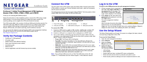
Installation Guide ProSecure™ Unified Threat Management (UTM) Appliance Models UTM5, UTM10, UTM25, UTM50, and UTM150Thank you for selecting NETGEAR products.Follow the instructions in this installation guide to connect the UTM using a single WAN interface, to use the Setup Wizard to configure the basic network and scanning settings, and to register the UTM and activate its licenses.The UTM models differ in the number of LAN and WAN ports that they provide. For information about the different models and about how to configure other options such as multiple WAN settings (not applicable to the UTM 5 and UTM10), the firewall, VPN tunnels, and custom scanning, see the reference manual.You can access the reference manual from the UTM’s web management interface, through the resource CD, and from the NETGEAR support site at.Verify the Package Contents•ProSecure™ UTM appliance•AC power cable•Rubber feet (4) with adhesive backing•Rack-mount brackets (some models)•Installation guide•Resource CD•Service registration card with license keys (some models)Connect the UTMThe front panel of the UTM contains ports and status LEDs; the back panel of theUTM contains a console port, Factory Defaults reset button, cable lock receptacle,and AC power connection.The following figure shows the front panel of the UTM150. The front panels of othermodels differ only in the number of LAN and WAN ports.To connect the UTM:1.Connect a WAN port to a cable or DSL modem, satellite dish, wireless ISPradio antenna, or other WAN device that has an active WAN connection.2.Connect a LAN port to a computer that is configured as a DHCP client.3.Turn on the UTM by connecting one end of the AC power cable to the ACreceptacle on the back panel of UTM and the other end to a power outlet. Afterabout 1 minute, verify the following:•Power LED. The Power LED is solid green.•Test LED. The amber Test LED is lit. The Test LED turns off when theinitialization process is completed, approximately 2minutes after you haveturned on the UTM.•WAN LED. The left LED of the connected WAN port is lit. If it is not, makesure that the Ethernet cable is securely attached to the WAN device and theWAN port, and that the WAN device is on.•LAN LED. The left LED of the connected LAN port is on. If it is not, makesure that the Ethernet cable from the computer to the UTM is securelyattached at both ends, and that the computer is on.Note:If any of these LEDs are not lit, or if the Test LED does not turn off, seeChapter 12, “Troubleshoot and Use Online Support,” of the reference manual.1.Power LED (green)2.Test LED (amber)B portN ports and LEDs5.DMZ LED for LAN port 46.WAN ports and LEDsLog In to the UTMTo log in to the UTM and access its web management interface:1.On the computer that is connected tothe UTM, enter https://192.168.1.1 inthe address field of a browser. TheNETGEAR Configuration ManagerLogin screen displays in the browser.2.Enter admin for the user name andpassword for the password, and clickthe Login button.The web management interfacedisplays.After 5 minutes of inactivity (the defaultlogin time-out), you are automaticallylogged out. You can change the login time-out by selecting Users > Users todisplay the Users screen and modifying the admin user settings.Use the Setup WizardThe Setup Wizard guides you through 10 screens to configure the basic networkand scanning configuration of the UTM.To access the Setup Wizard:1.Open the web management interface.2.Select Wizards.3.Select the SetupWizard radio button.4.Follow the SetupWizard to configurethe following settings:•LAN settings•WAN settings•System date and time, including NTP server configuration•Email and web services (that is, protocols) and ports to scan•Email security (antivirus settings) and scan exceptions based on sizehttps://192.168.1.1December 2012NETGEAR and the NETGEAR logo are registered trademarks of NETGEAR, Inc. in the United States and/or other countries. Other brand and product names are trademarks or registered trademarks of their respective holders. Information is subject to change without notice. © NETGEAR, Inc. All rights reserved.Intended for indoor use only in all EU member states, EFTA states, and Switzerland.•Web security (antivirus settings) and scan exceptions based on size•Web categories to be blocked•Email notification•Scan engine and signatures update settings5.Click the Apply button to save your changes.The UTM reboots. If the IP address of your computer is now on a differentsubnet, restart the computer to refresh its network settings so you can log in to the UTM again.Note:For detailed steps about how to configure the UTM by using the Setup Wizard, see Chapter 2, “Use the Setup Wizard to Provision the UTM in Your Network,” of the reference manual.Register the UTM and Activate the Licenses To receive threat management component updates and use telephone support, you need to register your UTM with NETGEAR. You might have purchased the UTM with a 1- or 3-year license. The UTM also comes with four 30-day trial licenses:•Web protection•Email protection•Support and maintenance•Application control and IPSIf your UTM is unregistered, you can use the 30-day trial period for all four types of licenses to perform the initial testing and configuration.Activating the licenses initiates their terms of use. Activate the licenses only when you are ready to start using the UTM. The 30-day trial licenses are revoked once you activate the purchased licenses.To register the UTM and activate the trial or purchased licenses:1.Make sure that the UTM has Internet access.2.Open the web management interface.3.Select Support > Registration. The Registration screen displays.4.Enter one of the license keys in the Registration Key field.plete the fields in the Customer Information and VAR Information sectionsof the screen.6.Click one of the following buttons:•Trial. Activates a trial license and registers the UTM with the NETGEARregistration and update server.•Register. Activates a purchased license and registers the UTM with theNETGEAR registration and update server.7.If necessary, repeat Step 4 and Step 6 for additional license keys.After the registration and activation are complete, the Registration screenshows the license keys and their expiration dates:Electronic Licensing OptionIf you have purchased the UTM with a 1- or 3-year license, you might be able to usethe electronic licensing option. When the UTM is connected to the Internet, youneed to enter only your customer information and optional value-added reseller(VAR) information on the Register screen but do not need to enter the licensenumbers. When you click the Register button, the UTM automatically downloadsand activates the license keys because the serial number of the UTM is linked to thelicense.If you have purchased a license from a VAR (either directly or over the web) afterpurchase of the UTM, the VAR should email you the license keys or provide them toyou in another way. To register and activate the license keys, follow the regularregistration procedure as explained in the previous section (see steps 1–7).Online Documentation and ResourcesFor extensive information about configuring and using your UTM, see the referencemanual, which you can access from or from theweb management interface.To access online documentation and resources:1.Open the web management interface.2.Select one of the following:•To view the reference manual, select Support > Documentation.•To view the product support page, select Support > Knowledge Base.Technical SupportVisit for product updates and web support.For the complete EU Declaration of Conformity, visit/app/answers/detail/a_id/11621/.NETGEAR recommends that you use only the official NETGEAR supportresources.。
Chief项目器安装指南说明书
PROJECTOR SECURITY GUIDEAvailable Color Options =I IIBASICALL-POINTS SECURITYTamper-resistant hardware at all key connectionpoints to deter theft.A D V A N C E DB A S I CM O U N T T Y P ERPA-xxx Custom Projector Mount I RPAU Universal Projector MountI I IRPA SeriesRPM-xxx Custom Projector Mount I RPMU Universal Projector MountI I IRPA Elite SeriesAccessoriesCMS115 Ceiling PlateI I I CMS-0XX0XX Adjustable Extension Column I I I CMA1521-1/2” to 1-1/2” NPT CouplerI IBlock projector theft and protect your AV investment!INTERMEDIATEPROJECTOR LOCKSSecures mount with key and lock security combined with All-Points Security.PL1(A/B/C)Projector Lock I PL2(A/B/C) Mini Projector LockI*For use with RPA-xxx SeriesPL Series RPM(A/B/C)-xxx Custom Projector Mount withQ-Lock Key Option A, B or CIRPM(A/B/C)-U Universal Projector Mount withQ-Lock Key Option A, B or C I I IRPA Elite with Q-Lock SECURITY MOUNTSAll-in-one security/mount solution that relies solely on key and lock security (no exposed fasteners).RPA(A/B/C)1All-In-One Security Mountwith Key Option A, B or CI IRPA Security SeriesRPM(A/B/C)1All-In-One Security Mountwith Q-Lock Key Option A, B or CI IRPA Elite Security SeriesSECURITY CABLESAdd additional security to any installation with security cables.PM-SC I*For use with RPA(A/B/C)1 and RPM(A/B/C)1 SeriesPM-SC Anchor PointsSA1 Security AnchorSSC4 Security Screw Cover KitsPROJECTOR GUARDSEncloses the mount and projector inside a steel cage for ultimate security.PG1A Projector GuardI IPG1SeriesPG2A Projector GuardI IPG2 SeriesLC1 Cable Lock PL4 Projector LockHC1HC1 Heavy Duty Cable SystemCable LocksIncludes Key &Lock Security =FOR A COMPLETE LIST OF ACCESSORIES, VISIT CMS445CMS-0XX0XXCMS115Model Type Max Weight Color(s)RPM*Custom 50 lbs (22.7 kg)I RPM-U*Universal 50 lbs (22.7 kg)I I IRPA Custom 50 lbs (22.7 kg)I RPA-UUniversal50 lbs (22.7 kg)I I IRPA Elite Projector MountCustom option shownModel Description Color(s)CMS115™Ceiling PlateI I I CMS ™-0XX0XX 1-1/2” NPT AdjustableI I I Extension Column CMS ™-0XX 1-1/2” NPT Fixed I I IExtension Column CMS440™Lightweight Suspended I Ceiling KitCMS445™Ceiling Tile Replacement Kit I CMA470™Plenum Enclosure for CMS440I*For Q-Lock integrated security, order RPMA, RPMB or RPMC with A, B or C designating the key option.PROJECTOR MOUNTSQ-Lock ™Integrated Locking LeverProvides enhanced security with an integrated key and lock system.*Optional – order RPMA/B/C with A, B or C to designate key optionMicroZone™Micro AdjustmentFor fast and precise projector registration, including flush-mount installations.Centris ™ Technology Fingertip Adjustment Enables effortless, fingertip positioningCMS440CMA470ACCESSORIESALSO AVAILABLERPA ™Projector MountUniversal Option ShownI Independent Roll, Pitch and Yaw I Integrated Cable ManagementI Quick Projector Connect/Disconnect IAll-Points ™Security SystemCHI EF MANUFACTURI NGA DIVISION OF CSAV , INC.USA/INTERNATIONAL I 8401 EAGLE CREEK PARKWAY, SAVAGE MN 55378 USA******************P 800.582.6480I 952.894.6280F 877.894.6918I 952.894.6918CHI EF MOUNTS CANADA I 2-310 FI RST STR, MI DLAND ON L4R 3N9 CANADA*******************P 877.345.4329I F 888.377.5314CSAV EUROPE B.V.I FELLENOORD 130, 5611 ZB EI NDHOVEN, NETHERLANDS************************P +31 (0) 40 2668620I F +31 (0) 40 2668615CSAV ASI A PACI FI C LTD I ROOM 29G, H, I , LI LY YI NDU I NTERNATI ONAL BUI LDI NG,**********************LUOGANG, BUJI TOWN, SHENZHEN, CHI NA, 518112P 86 755 8996 9226I F 86 755 8996 9217©2007 CSAV , Inc. Printed in the USA. 100127A 3/07. Chief is a registered trademark of CSAV , Inc. All other brand names ormarks are used for identification purposes and are trademarks of their respective owners. All patents are protected under existing designations. Other patents pending.PROJECTOR SECURITY GUIDE。
UTM设备安装指南说明书
Installation GuideFamiliarize yourself with the connectors and controls on the back of the unit.Complete the Basic SetupFollow these steps to quickly setup the UTM appliance.Connect the UnitFor initial setup, connect the WAN Ethernet port to an active WAN connection such as a broadband modern, connect a DHCP enabled PC to a LAN port, and turn on the unit.Verify the following:• Power LED : It takes about a minute to boot. The power LED should turn solidgreen. If it does not, see the Troubleshooting section of the Reference Manual . • Test LED : When you first turn on the unit, the amber test LED will be lit forapproximately 2 minutes.• WAN Status LED : The status LED on the connected WAN port should be lit. Ifnot, make sure the Ethernet cable is securely attached to the modem and the WAN port, and that the modem is powered on.• LAN Status LED : A LAN status LED should be lit. If not, ensure that the Ethernetcable from the computer to the unit is securely attached at both ends, and that the computer is turned on.Log in to the Unit1. Use a browser to connect tohttps://192.168.1.1.7. Kensington lock 8. Console port 9. Factory reset button10. Power connector7109https://192.168.1.12. When prompted, enter admin for the UserName and password for the Password. Click Login.You are now connected. After 5 minutes of inactivity (the default login time-out), you are automatically logged out.Note: When the unit scans secure HTTPS traffic, import its root CA certificate into client browsers. Click the link at the bottom of the login screen to download it.Use the Setup Wizard for Basic ConfigurationThe Setup Wizard will guide you through the basic network and scanning setup. Note: If you choose to bypass the Setup Wizard, be sure to configure an alerts email address and change the admin password.1. Start the Setup Wizard.Select Wizards > SetupWizard to start the wizard.For guidance on how to fill in the wizard screens, refer to the online help or the Reference Manual via a link in theSupport > Documentation page.2. Use the Setup Wizard to configure these basic network and scanning settings:• LAN and WAN network settings.• System time (NTP server) and time zone.• Scanning of network protocols and services.• Default scan actions when the unit detects threats.• Scan exceptions like the maximum file size.• Specify the notification server and notices to be used in email notifications.•Scan engine and signature updates.ProSecure™ Unified Threat Management (UTM) ApplianceFollow these instructions to configure your ProSecure Unified Threat Management appliance to use a single WAN interface, and enable the default threat management scanning. Then, consult the Reference Manual for instructions on configuring other options such as multiple WAN settings, VPN, firewall, and custom scanning. You can access the Reference Manual from the product management interface, via the Resource CD and from the NETGEAR support site: . Estimated time: 30 minutes.Verify the Package Contents• ProSecure™ UTM appliance. • Installation Guide.• Resource CD.• Rubber feet (4) with adhesive backing.• Rack mount brackets (some models).• Power cord.Familiarize Yourself with the UnitFamiliarize yourself with the ports and status lights on the front of the unit.1.Green power LED2.Amber test LEDB port (for future use)4.Gigabit LAN portsN port 4 DMZ identifier6.Gigabit WAN ports, dualWAN model shown12536November 2010This symbol was placed in accordance with the European Union Directive 2002/96 on the Waste Electrical and Electronic Equipment (the WEEE Directive). If disposed of within the European Union, this product should be treated and recycled in accordance with the laws of your jurisdiction implementing the WEEE Directive.©2010 by NETGEAR, Inc. All rights reserved. NETGEAR and the NETGEAR logo are registered trademarks of NETGEAR, Inc. in the United States and/or other countries. Other brand and product names are trademarks or registered trademarks of their respective holders. Information is subject to change without notice.3. Click Apply to save your changes.The unit will reboot. Your computer will lose its connection to the unit if its IP address is now on a different subnet. If so, restart the computer to refresh its network settings.LicensesYour unit is bundled with three 30-day trial licenses.• Web scanning • Email scanning• Support and maintenanceActivating the licenses starts their term of use. Activate the licenses only when you are ready to start using this unit. If your unit has never been registered before you can use the 30 day trial period for all 3 types of licenses to perform initial testing and configuration.Note: Be sure the unit has Internet access before registering the licenses.• Activate the trial licenses by selecting Support > Registration and click the “Trial ” button. Once you activate the trial licenses, you can then update the unit with the latest UTM build and signature & engines during the 30-day trialperiod.• If you purchase a license subscription bundled with your unit, a license will be assigned to your unit’s serial number. When you register your unit, the license key will automatically be downloaded to your unit. Select Support > Registration , fill out the registration page, and click “Register ” to activate the services. Note: the 30-day trial licenses will be revoked once you activate the purchased service license keys. The purchased service license keys offer one year or three years of service.For additional information on licenses see the reference manual.Register and Activate the LicensesNote: Be sure the unit has Internet access before registering the licenses.1. Log in to the unit.2. Select Support > Registrationto display the Registration tab.3. Enter the customer information. If using the trial licenses, click Trial . If youhave purchased licenses, click Register . The unit will activate the licenses. After registration is complete the unit will display the license keys and their expiration dates.Online Documentation and SupportSelect Support > Documentation to view the reference manual. Select Support > Knowledge Base to view the support page, which includes this document and the reference manual. Going to/support and selecting your product modelnumber takes you to the same page.Consult the reference manual for instructions on how to use the online supportremote diagnostics.Technical SupportThank you for selecting NETGEAR products.After installing your device, locate the serial number on the label of your product and use it to register your product at /register . Registration is required before you can use the telephone support service. Registration via our website is strongly recommended.Go to for product updates and Web support . For additional information about setting up, configuring, and using your Product Name Only, see the User Manual .For complete DoC please visit the NETGEAR EU Declarations of Conformity website at: /app/answers/detail/a_id/11621/。
SVS多媒体中央控制系统安装使用手册
中文版SVS——可编程中央控制系统——安装使用手册Ⅰ型中控口Ⅱ型中控口Ⅲ型中控口Ⅳ型中控口Ⅴ型中控口Ⅵ型中控口Ⅶ型中控口可编程多媒体中央控制系统安装使用手册2005 [08]SVS(迅控)多媒体中央控制系统型号对应说明:1、Ⅰ型中控----------------------------------------SV-32002、Ⅱ型中控----------------------------------------SV-33003、Ⅲ型中控----------------------------------------网络中控SV-4500/6000/8000/90004、Ⅳ型中控----------------------------------------SV-36005、Ⅴ型中控----------------------------------------SV-3500/38006、Ⅵ型中控----------------------------------------SV-20007、Ⅶ型中控----------------------------------------SV-2500目录第一章、注意事项: (6)第二章、产品简介 (6)概述 (6)1.Ⅰ型智能中控系统 (6)2.Ⅱ型智能中控系统 (7)3.Ⅲ型智能中控系统 (7)4.Ⅳ型智能中控系统 (8)5.Ⅴ型智能数码中控系统 (8)6、Ⅵ、一体化可编程多媒体中央控制系统 (8)7、Ⅶ型一体化可编程中央控制系统 (9)第三章、设备包装说明 (9)第四章、中控前面板图 (10)第五章、主控机后面板示意图 (10)1.Ⅰ型主控机后面板 (10)2.Ⅱ型主控机后面板 (10)3.Ⅲ型主控机后面板 (10)4.Ⅳ型主控机后面板 (10)5.Ⅴ型主控机后面板 (11)6.Ⅵ一体化中控后面板 (11)7.Ⅶ一体化中控后面板 (12)第六章、系统主机、电脑的连接 (12)第七章、应用设备连接示意图 (12)1、Ⅰ、Ⅱ智能中控系统 (13)1、Ⅲ型智能中控系统 (13)2、Ⅳ型智能中控系统 (13)3、Ⅴ型智能数码中控系统 (13)4、Ⅵ型一体化中央控制系统 (13)7Ⅶ型一体化中央控制系统 (13)第八章、红外发射棒的连接 (13)第九章、投影机控制线连接: (14)第十章、电动屏幕接线图 (14)第十一章、操作面板使用说明 (14)1、29键LED控制面板的应用 (14)2、43键面板 (15)3、55键LCD液晶面板的应用 (16)4、55键VFD液晶面板的应用 (18)5、Ⅵ型一体化面板 (19)6、Ⅶ一体化中控面板 (20)第十二章、设备红外遥控器代码的学习和录入 (21)第十三章、红外控制器的使用(选配件) (22)第十四章、主控机系统各项参数 (22)第十五章、常见故障排除 (24)1、通过面板“系统开”无法开机 (24)2、面板控制不灵 (24)3、有些设备红外遥控不灵 (24)4、电脑软件无法控制 (24)5、红外学习不成功或显示成功却不能遥控 (24)6、投影机无法控制 (24)7、灯光开/关干扰投影机信号 (24)8、灯光开关干扰中控内部程序 (25)第十六章、可编程多媒体中央控制系统软件简介 (25)1.实时双向控制 (25)2.电教系列可编程功能按键 (26)3.无代码方式 (26)4.功能按键的扩展 (26)5.第三方设备的控制 (26)6.视频监视、预览窗口 (26)7.密码保护 (26)8.调整视图 (26)9.系统运行环境 (26)10.通讯串行口参数说明 (26)11.系统安装 (27)第十七章、可编程多媒体中央控制系统软件相关说明 (27)1.关于双向控制 (27)2.系统界面说明 (27)3.视频监视窗口 (28)4.系统栏按键: (28)5.设备栏按键: (28)6.控制栏按键: (28)7.标题栏: (28)8.反馈信息栏: (29)9.监视功能常用键 (29)10.栏目属性: (29)11.工具栏按键说明 (29)12.系统 (29)13.常用类按键说明 (32)14.备栏按键的添加及编辑: (33)15.注意事项 (35)第十八章、本手册说明 (35)附录一、网络中控详细说明 (36)附录二、最新培训教材 (39)概述感谢您购买和使用本公司的产品,在使用本机前请细阅这本用户手册以便能正确使用并且请妥善保存这本手册万一有不了解或故障时这本手册会带给您很大的帮助。
Informatica PowerCenter 8.6.1安装配置手册
Informatica PowerCenter 8.6.1安装配置手册2009年10月提交人:杜绍森版本号: 1.0目录安装前准备事项 (4)PowerCenter 8.6.1对系统的配置要求 (4)PowerCenter 8.1对数据库的配置要求 (6)PowerCenter 8.6.1对第三方软件的要求 (7)PowerCenter在UNIX下的安装 (9)配置UNIX用户的环境变量 (9)安装Domain和第一个Node (10)执行install.bin –i console命令 (10)指定PowerCenter服务的license key (12)定制化安装 (13)选择安装PowerCenter Services为例 (13)设定第一个Node的根路径 (14)创建新Domain (15)设定Domain的 Metadata库 (15)安装成功 (16)登陆到控制台 (18)安装后续Node (19)执行install.bin –i console命令 (19)指定PowerCenter服务的license key (21)定制化安装 (22)选择安装PowerCenter Services (22)设定新Node的根路径 (23)加入现有Domain (24)设定Domain信息 (24)设定新Node信息 (25)安装成功 (25)登陆到控制台 (27)PowerCenter在Windows下的安装 (28)选定“Server”安装选项 (28)欢迎界面 (29)为PowerCenter指定license key (30)安装前的必备条件 (30)指定PowerCenter的安装根路径 (31)选择是否启用HTTPS (31)安装需求总结 (32)安装进行过程中。
(33)选择是否创建新的Domain (33)配置存储Domain配置信息的数据库连接信息 (34)配置域信息 (34)配置Informatica Services启动用户 (35)PowerCenter Services的安装总结 (36)对应的安装日志 (36)Logon 管理控制台(Admin Console) (37)登陆后的页面 (38)创建Repository Service (39)客户端安装非常简单,这里不再敖续 (46)PowerCenter 8.1管理操作 (46)登陆到Administration Console (46)创建Repository Service.........................................................................错误!未定义书签。
- 1、下载文档前请自行甄别文档内容的完整性,平台不提供额外的编辑、内容补充、找答案等附加服务。
- 2、"仅部分预览"的文档,不可在线预览部分如存在完整性等问题,可反馈申请退款(可完整预览的文档不适用该条件!)。
- 3、如文档侵犯您的权益,请联系客服反馈,我们会尽快为您处理(人工客服工作时间:9:00-18:30)。
Patrol central安装配置手册
目录
一、安装环境 (2)
二、安装步骤 (2)
2.1创建用户 (2)
2.2Patrol central安装步骤 (8)
1 / 18
一、安装环境
二、安装步骤
2.1创建用户
创建patrol用户,并将其加入administrator组,在桌面右键单击计算机,点击“管理”,打开服务管理器,展开配置——本地用户和组,如下图
2 / 18
在用户上右键单击,点击“新用户”,用户名:patrol全名:patrol密码自定义。
勾选“用户不能更改密码”和“密码永不过期”,点击创建完成,如下图
在patrol用户上右键单击,点属性,如下图:
3 / 18
点击“隶属于”,然后点击“添加”按钮,如下图:
4 / 18
点击“高级”按钮,如下图:
5 / 18
6 / 18
点击“立即查找”按钮,如下图
:
选中administrator,点击确定,如下图:
点击确定,如下图:
7 / 18
点击确定,完成。
2.2P atrol central安装步骤
切换到patrol用户,打开patrol central文件夹,如下图,
8 / 18
双击“setup”开始安装,弹出浏览器安装界面(如不能打开IE页面,可能是IE阻止弹出窗口,可手动打开IE,点击工具——弹出窗口阻止程序——关闭弹出窗口阻止程序),如下图:
点击“Next”,如下图:
9 / 18
选择“accept”,点击“Next”,如下图:
10 / 18
点击“Next”,如下图:
点击“Next”,软件包全选,如下图:
11 / 18
点击“Next”,如下图:
12 / 18
点击“Next”,如下图:
点击“Next”,如下图:
13 / 18
点击“Next”,将localhost改成RTserver服务器地址,如果RTserver与patrolcentral 部署在同一台服务器,则只需改成本机IP地址,如果RTserver与patrol central分开部署,则要填写RTserver服务器地址。
如下图:
点击“Next”,如下图:
14 / 18
点击“start install”开始安装,如下图
15 / 18
点击“Next”,显示安装成功,如下图:
16 / 18
点击“Next”,如下图:
17 / 18
点击“Finish”,安装完毕。
18 / 18。