西北工业大学《材料科学基础》课后题答案
材料科学基础课后习题答案5
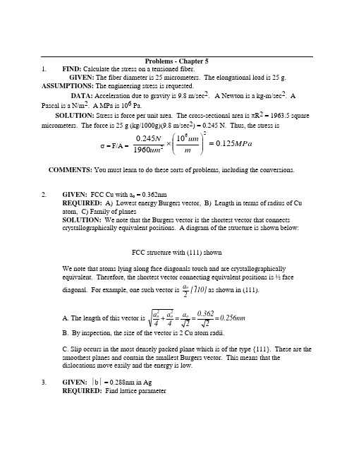
Problems - Chapter 5 1. FIND: Calculate the stress on a tensioned fiber.GIVEN: The fiber diameter is 25 micrometers. The elongational load is 25 g. ASSUMPTIONS: The engineering stress is requested.DATA: Acceleration due to gravity is 9.8 m/sec 2. A Newton is a kg-m/sec 2. A Pascal is a N/m 2. A MPa is 106 Pa.SOLUTION: Stress is force per unit area. The cross-sectional area is πR 2 = 1963.5 square micrometers. The force is 25 g (kg/1000g)(9.8 m/sec 2) = 0.245 N. Thus, the stress isσ = F/A = MPa m um um N 125.010*******.0262=⎪⎪⎭⎫⎝⎛⨯COMMENTS: You must learn to do these sorts of problems, including the conversions. 2. GIVEN: FCC Cu with a o = 0.362nmREQUIRED: A) Lowest energy Burgers vector, B) Length in terms of radius of Cu atom, C) Family of planesSOLUTION: We note that the Burgers vector is the shortest vector that connects crystallographically equivalent positions. A diagram of the structure is shown below: FCC structure with (111) shownWe note that atoms lying along face diagonals touch and are crystallographically equivalent. Therefore, the shortest vector connecting equivalent positions is ½ facediagonal. For example, one such vector is 10]1[ 2ao as shown in (111).A. The length of this vector is 0.256nm = 20.362= 2a = 4a + 4a o 2o 2oB. By inspection, the size of the vector is 2 Cu atom radii.C. Slip occurs in the most densely packed plane which is of the type {111}. These are the smoothest planes and contain the smallest Burgers vector. This means that the dislocations move easily and the energy is low. 3. GIVEN: ∣b ∣ = 0.288nm in AgREQUIRED: Find lattice parameterSOLUTION: Recall the Ag is FCC. For FCC structures the Burgers vector is ½ a facediagonal as shown. We see that 4.A. FCC structureThe (111) plane is shown in a unit cell with all atoms shown. Atoms touch along face diagonals. The (111) plane is the most closely packed, and the vectors shown connectequivalent atomic position. Thus 10]1[ 21 = b etc. Then in general >110< 2a= bB. For NaC1We see that the shortest vector connecting equivalent positions is 10]1[ 2aas shown.This direction lies in both the {100} and {110} planes and both are possible slip planes. However {110} are the planes most frequently observed as the slip planes. This is because repulsive interionic forces are minimized on these planes during dislocation motion. Thus we expect 1/2<110> Burgers vectors and {110} slip planes. 5.GIVEN:Mo crystal 0.272nm = b a o = 0.314nmREQUIRED: Determine the crystal structure.If Mo were FCC, then 0.222nm = 20.314= b __but |b| = 0.272 ⇒ Mo is not FCC. Assuming Mo is BCC, then 0.272nm. = 0.314 X 23= b __Thus the Burgers vector is consistent with Mo being BCC. 6.FIND: Is the fracture surface in ionic solids rough or smooth?SOLUTION:Cleavages surfaces of ionic materials are generally smooth. Once a crack is started, it easily propagates in a straight line in a specific crystallographic direction on a specific crystallographic plane. Ceramic fracture surfaces are rough when failure proceeds through the noncrystalline boundaries between small crystals.7. GIVEN: BCC Cr with |b| = 0.25nmREQUIRED: Find lattice parameter aASSUME: >111< 2a= b for BCC structureSOLUTION:2a 3= 4a + 4a + 4a = b 222__from the formula for the magnitude of a vector:8. GIVEN: Normal stress of 123 MPa applied to BCC Fe in [110] directionREQUIRED: Resolved shear in [101] on (010)SOLUTION: Recall that the resolved shear stress is given by: τ = σ cos θ cos φ (1)where θ = angle between slip direction and tensile axis; φ = angle between normal to slip plane and tensile axisThus MPa 43.5 = 21 21 123 = ⎪⎭⎫⎝⎛⎪⎭⎫ ⎝⎛τ9. GIVEN: Stress in [123] direction of BCC crystalREQUIRED: Find the stress needed to promote slip if τcR = 800 psi. The slip plane is (11_0) and slip direction is [111]. SOLUTION: Recall τ = σ cos θ cos φ (1) θ = [123] [111][123] ⋅ [111] = ∣[123]∣ ∣[111]∣cos θφ = [123] [11_0][123] ⋅ [11_0] = ∣[123]∣ ∣[11_0]∣cos φ10.Burgers vectors lie in the closest packed directions since the distance between equivalent crystallographic positions is shortest in the close-packed directions. This means that the energy associated with the dislocation will be minimum for such dislocations since the energy is proportional to the square of the Burgers vector.11. Close packed planes are slip planes since these are the smoothest planes (on an atomic level) and would then be expected to have the lowest critical resolved shear stress. 12.GIVEN: Dislocation lies on (11_1) parallel to intersection of (11_1) and (111) with Burgers vector parallel to [1_1_0]. Structure is FCC.REQUIRED: A) Burgers vector of dislocation and, B) Character of dislocation.SOLUTION: A) Since the structure is FCC, the Burgers vector is parallel to <110> andhas magnitude . 2aFor a Burgers vector parallel to [1_1_0] the scalar multiplier must be a/2. Thus b _ = a/2 [1_1_0]. B) We must determine the line direction of the dislocation. From the diagram we see that the BV and line direction are at 60o which means the dislocation is mixed.13. GIVEN: Dislocation reaction below:REQUIRED: Show it is vectorially correct and energetically proper.SOLUTION: [100] a =] 111[ 2a+[111]2a The sum of the x, y & z components on the LHS must be equal to the corresponding component on the right hand side.x component (LHS) = x component (RHS)y component (LHS) = y component (RHS) z component (LHS) = z component (RHS)Energy: The reaction is energetically favorable if | b 1 | 2 + | b 2 | 2 > | b 3| 3Thus the reaction is favorable since a >a 43+ a 4322214. GIVEN: Dislocation in FCCParallel to [1_01] i.e. t_ = [1_01]REQUIRED: Character and slip planeSOLUTION: Character is found by angle between b_ and t_. Note b_t_• = -1 + 0 + 1 = 0. Thus b__t_. Since b__t_the dislocation is pure edge.To find the slip plane we note that the cross produce of t_ & b_gives a vector that is normal to the plane in which t_ & b_lie. This vector so formed has the same indices as the plane since we have a fundamentally cubic structure.We see from the diagram that these vectors lie on (010).Thus, we have the plane (01_0) which is the same as the (010) plane. This does not move by glide since planes of the kind {100} are not slip planes for the FCC structure.15.FCC metals are more ductile than BCC or HCP because: 1) there is no easy mechanism for nucleation of microcracks in FCC as there is for BCC and HCP; 2) the stresses for plastic deformation are lower in FCC due to the (generally) smoother planes. This means that the microcracks that form in BCC & HCP will have high stresses tending to make them propagate.16. For a simple cubic system, the lowest energy Burgers vectors are of the type <001> since this is the shortest distance connecting equivalent atomic positions. This means that the energy is lowest since the strain energy is proportional to the square of the Burgers vector. 17.GIVEN:At. wt. 0 = 16At. wt. Mg = 24.32 Same structure as NaCl ρ = 3.65 g/cm 3REQUIRED: Find length of Burgers Vector in MgOSOLUTION: The structure of MgO is shown schematically below along with the shortest Burgers vector. To solve the problem we first note that we require the lattice parameter a o . We can take a sub-section of the unit cell (cross-hatched cube) whose edge is 2a o units long.We can calculate the total mass of this cube and the volume and calculate the density. Since the mass is known and the density is known, the volume may be calculated from which a o may be extracted.O= and ½ Mg++ ions in our cube.Thus10x3.35x88/a10x2.02)+(1.33=3.65-233o-2318. GIVEN: Critical resolved shear stress (0.34MPa), slip system (111)[1_10], and tensileaxis [101]REQUIRED: Applied stress at which crystal begins to deform and crystal structure.SOLUTION: (A)The situation is shown belowτcrss = σ cosθ⋅ cosφθ = angle between tensile axis and slip directionθ = angle between tensile axis and normal to slip planeφ = [111] [101] θ = [101] [1_01][111] ⋅ [101] = ∣[111]∣∣[101]∣cosφ [101] ⋅ [110] = ∣[101]∣∣[110]∣cosθ(B): To have a {111}<110> slip system, the material must have an FCC structure.19. GIVEN:τcrss = 55.2 MPa, (111)[1_01] slip system, [112] tensile axisREQUIRED: Find the highest normal stress that can be applied before dislocationmotion in the [10 1_] direction.SOLUTION: The situation is shown below. Essentially the problem reduces to finding the value of the tensile stress when the critical resolved shear is reached.τcrss = σ cosθ⋅ cosφθ = [112] [1_01] φ = [112] {111}B. Would have exactly the same stress for a BCC metal (φ & θ would be interchanged).20. GIVEN:σ at yield = 3.5 MPa; (111) [11_0] slip system [11_1] tensile axisREQUIRED: Compute τcrssSOLUTION:τcrss = σcosθcosφθ = [11_1] [11_0] φ = [11_1] [111]21. Item Edge ScrewLinear defect? Yes YesElastic Distortion? Yes YesGlide? Yes YesClimb? Yes NoCross-slip? No YesBurgers Vector (BV) ⊥ to line // to lineUnique slip plane? Yes NoOffset // to BV // to BVMotion // to BV⊥ to BV22.GIVEN: BCC metal with τcrss = 7MPa [001] tensile axis.REQUIRED: (a) Slip system that will be activated and (b) normal stress for plastic deformation.SOLUTION: Recall that for BCC metals the usual slip system is <111> {110}.Deformation occurs on the plane and direction for which cos θ⋅cos φ is a maximum since this will have the maximum resolved shear stress. The situation is shown below.(Note that the slip directions are shown shortened in this view)Possible slip systems are listed below:sketch (also [11_1] on (011)) (also [1_11] on (01_1)) (also [1_1_1] on (101)) similar to planes shown in sketch. Also [111] on (1_01)We see by inspection that the resolved shear due to a tensile force in [001] will all be the same. The resolved shear on all other {110}<111> systems is zero.B. To compute the normal stress at the onset of plastic deformation we will consider (011) [1_1_1]τcrss = σcos θcos φ = 7θ = [001] [1_1_1]; cos φ = [001] [011]Note if we considered (101) [1_1_1] we would haveand we would obtain exactly the same answer.23. GIVEN: Yielding occurs at normal stress of σ = 170 MPa in [100] direction.Dislocation moves on (101) in [111_] direction.REQUIRED:τcrss and crystal structuresSOLUTION: Assume an edge dislocation. τcrss = σcos⋅cosφθ = [100] [111_] φ = [100] [101]The - sign means that the slip direction is opposite to the motion of the dislocation.Essentially, we have a negative edge dislocation on (101) as shown below:The edge dislocation moves in [111_] direction but the offset is in [1_1_1] direction.The slip plane and slip direction are representative of BCC structures.24. GIVEN: (1_10)[111] slip system. [123] tensile axisτcrss = 800 psi for BCC crystalτcrss = 80 psi for FCC crystal withσFCC = 457 psi [123] tensile axis and (111)[11_0] system.REQUIRED: Normal stress at yield for BCC metalSOLUTION: The simplest way to solve this problem is to note cosθ⋅cosφ is the same for the BCC and FCC crystal with the meaning of φ and θ interchanged. Let M = cosθ⋅cosφ.(1)(2)25.Here crystallographically equivalent positions join ions at cube corners (b v = a o ), face diagonals )a 2 = b (o v , cube diagonals )a 3 = b (o vThe most densely packed plane is the (110) in which we haveThe shortest vector that will reproduce all elements of the structure is a o . Thus b = a<100>COMMENT: We note that this is not sufficient for general deformation (e.g. a tensile axis of the type <100> produces zero shear on the 1<100> Burgers vectors. We expect then a<110> Burgers vectors as well. 26.GIVEN: σ = 1.7 MPa [100] tensile axis (111)[101] slip systemsREQUIRED: τcrss , and crystal structure. Also find flaw in problem statement.SOLUTION: Since the slip system is of the type {111}<110> the structure is FCC. The problem is misstated since the Burgers vector must lie on the slip plane and [101] does not lie on (111). The slip direction would more appropriately be [101_]. Thus the slip system is (111)[101_] as shown below.27.⊥ = edge dislocation x = start of Burgers circuitb = Burgers vector y = end of Burgers circuit28. FIND: Show energy/area = force/length, that is, surface energy is surface tension inliquids.DATA: The units of energy are J = W/s or N-m. The units of force are N.SOLUTION: Energy/area = J/m2 =N-m/m2 = N/m = force/length29. GIVEN: Two grain sizes, 10μm and 40μmREQUIRED: A) ASTM GS# for both processes, B) Grain boundary area.SOLUTION: Assume that the grains are in the form of cubes for ease of calculation.The ASTM GS# is defined through the equation: n = 2N-1 where n = # grains/in2 at 100X.N=ASTM GS#To solve the problem we first convert the grain size to in. where D = length of cube edge in μm.At 100X linear magnification, the sides of the smaller grains will be:The area of each grain at 100X will beSimilarly the area of the 40μm grains at 100X isFor the 10μm dia grain, the # of grains per in 2 (at box) is645.16 = 10 x 1.5501 = n 3-100X10μgrains/in 2 at 100X Similarly 40.31= 10x 24.811 = n 3-100X 40μgrains/in 2at 100X For the 10μm grain size:B. In computing the total g.s. area we will assume 1 in 3 of materials. Since there are 6 faces cube and the area of each face is shared by 2 cubes, each cube has an area of 3xArea of face. G.B. Area =d / 3 = d 3 x d 123⎥⎦⎤⎢⎣⎡GB Area (10μ gs) = 3/3.937 x 10-4 = 7620in 2/in 3 GB Area (40μ gs) = 3/15.75 x 10-4 = 1905in 2/in 3 30.GIVEN:σys = 200MPa at GS#4 = 300MPa at GS#6REQUIRED: σys at GS#9SOLUTION: Recall σys = σo + kd -1/2 (1) for low carbon steel. If d = grain size (assume cubes) load = grain diameter at 100X4For ASTM GS#6:23.78 = d11/24(5) Substituting (4) and (5) into (1) we have200 - σo + k(16.82) (6) 300 = σo + k(23.78)(7)Subtracting (6) from (7):100 = k(23.78 - 16.82)∴k = 14.37Substituting this value of κ into (6) yields 200 = σo + 14.37 x 16.82σo = -41.70 (this is not physically realistic since σo relates to the lattice friction stress which should not be negative)For ASTM GS#9Thus σys = σo + 14.37 x 40 = 41.70 + 574 = 533MPa 31.GIVEN: ∣b ∣ = 0.25μm for BCC metal tilt boundary has angular difference of 2.5o REQUIRED: Dislocation density in tilt boundary wall SOLUTION: The physical situation is shown below:If b = Burgers vector, D = spacing between edge dislocation# of dislocations in boundary for a 1cm high boundary isD1(where D is in cm)32.33. FIND: Show D = b / θ.GIVEN: b is the magnitude of the Burger's vector; D is the spacing betweendislocations, and θ is the tilt angle.SKETCH: See Fig. 5.3-4.SOLUTION: We can see the geometry more clearly using the following sketch:From the Figure we can immediately write that tan/θ22=bD. Since the tan of a small angle isthe angle itself:θ22=bD/, so that D = b / θ, as is written in the margin.34. FIND: How can you detect a cluster of voids or a cluster of precipitates in a material?SOLUTION: This can be a difficult challenge indeed. If the total void volume islarge, then the density of the sample will be lower than that of dense material. Thesame is true for clusters of precipitate; however, usually the density difference between host and precipitate is not as great as between host and air, so the technique does notwork as well. Another possible technique is microscopy. Samples can be prepared for microscopy, perhaps by polishing and etching and the defects observed using opticalor electron microscopy. X-ray diffraction can also be used. With a random spacing of void or precipitate there is then an average spacing. Sometimes Bragg's law can beused to calculate the spacing if an intensity maximum is observed. Note that the angle of the maximum will be very small.COMMENTS: There are many other potential techniques that can potentially be used.They all rely on some property difference - magnetic, electrical, optical, or whatever.35. FIND: How can you ascertain whether a material contains both crystalline andnoncrystalline regions?GIVEN: Recall that the density (and other properties) of crystalline material is greater than that of noncrystalline material of the same compositionSOLUTION: There are three methods in common usage to establish crystallinitypolymers. These methods apply to all materials.1. Density. Measure the density of your sample and compare it to the density ofnoncrystalline and crystalline samples of the same composition.2. Differential Scanning Calorimetry. Heat your sample in a calorimeter. Samplesthat are crystalline will absorb heat at the melting temperature and show a "meltingendotherm". Some noncrystalline samples (such as amorphous metals) will crystallize in the calorimeter and show a huge release of heat prior to melting. This is a"crystallization exotherm".3. X-ray diffraction. Crystalline materials show well-defined peaks.COMMENTS: Knowing whether a material is crystalline or noncrystalline is acommon challenge to polymers scientists. We often need to quantify the fraction orpercent crystallinity. Can you suggest a method for each of the 3 techniques outlined?36. FIND: State examples of materials' applications that require the material to behave ina purely elastic manner.SOLUTION: There are many such possible examples. Since plastic deformation isnonrecoverable deformation, any application that requires repeated stressing anddimensional stability is a good example. Here are some examples:1. Springs in automobiles - leaf and coil springs2. A diving board3. Trusses in a bridge4. The walls in a building5. A bicycle frame6. Piano wire7. Airplane wings37. As the dislocation density ↑, there are more dislocation/dislocation interactions andthe strength goes up. At the same time, the degree of “damage” also increases and the ductility decreases.38. If the point defect concentration ↑, the strength will go up as well. This is because thedefects may migrate to edge dislocations where they cause jogs on the dislocations. A jogged dislocation is much harder to move and may itself require the generation ofpoint defects to move. In addition the point defects may collapse to form dislocationloops which also impede the motion of other dislocations making the materialsstronger. If the defects are interstitials, they may migrate to areas around thedislocations in which the system energy is reduced. For the dislocation to move away from the interstitial an increase in the system energy is required which means the stress to move the dislocation must increase. If the point defect is a substitutional atom,similar considerations apply. However, the magnitude of the energy reduction is less because of the less severe distortion. Thus the strength increase is not as high as forintersitital.39. As d↓σys↑ since this means the path over which a dislocation moves ↓. This meansthat the stress will have to increase to either nucleate or unlock dislocations in adjacent grains. The relationship quantifying this behavior is the Hall-Petch equation: σys = σo + kd-1/240. The strength may increase as a result of:1. decreasing grain size - should not be too (see previous questions) temperaturedependent.2. Adding impurities (e.g. C in Fe). The impurities “lock” the dislocation byassociating with the dislocation to lower the system energy. This will be verytemperature dependent for dilute concentrations of impurities as the impurities willdiffuse away at high temperatures.3. Adding precipitates - blocks the motion of dislocations through either having adifferent crystal structure or a large strain field. Since the precipitates are usually large compared to the atomistic dimension, strong temperature dependence is not expected.4. Cold work - increase quantity of dislocations.41. GIVEN: = 1012/cm 2 for low C steelREQUIRED: concentration of C atoms (at %) to lock all dislocationsSOLUTION: Recalling the At. weight of Fe is 55.85 and the density is about 7.8gm/cm 3 we may write 10 x 6.02 55.857.8 = N 23Fc(assume 1C atom for every Fe atom along dislocations)42. FIND: Why can you not bend the bar of tin?GIVEN: The bar has been well annealed, so the initial dislocation density is low. You are required to re-bend the bar after cold working.SOLUTION: The deformation has increased the dislocation density and the bar nowrequires much more stress, or force, to deform it. You are not necessarily a weakling, but you have been taken. Re-anneal the bar and bend it back or use brute force. COMMENTS: It is often difficult to bend a metal back to its original shape and this is just one of many possible reasons that depend on the metal and its thermo-mechanical%at10x4.76=10x8.4110x4_100x10x4+10x8.4110x4=%Cat10x4=10x2.510=10x2.510=Ncm10x2.5_ddcm10=N2-222119221919198-12c8-FeFe12c。
材料科学基础课后作业答案
2
2
2
此反应满足几何条件但不满足能量条件,反应不能成立。
8. 在钢棒的表面,每20个铁的晶胞中有一个碳原子,在离表面
1mm处每30个铁的晶胞中有一个碳原子。温度为1000℃时扩散
系数是3×10-11m2/s,且结构为面心立方(a=0.365 nm)。问每
分钟因扩散通过单位晶胞的碳原子数是多少?
由已知可以计算出碳的浓度: C2=1/[30*(0.365×10-9m)3]=0.68×1027 /m3 C1=1/[20*(0.365×10-9m)3]=1.03×1027 /m3
a
b
• (c)[0 1 2]
(d)[1 3 3]
• (e)[1 1 1]
(f)[1 2 2]
• (g)[1 2 3]
(h)[1 0 3]
3. Determine the indices for the directions shown in the following cubic unit cell:222
此反应满足几何条件和 能量条件,反应能进行 。
解2: a[100] a [111] a [1 1 1]
2
2
(1)几何条件
反应前 a[100]
反应后
a [111] a [1 1 1]= a [200] a[100]
2
2
2
(2)能量条件
反应前
b2 a2
反应后
b2 ( a 12 12 12 )2 ( a 12 12 12 )2 3 a2 a2
9. 某固溶体的合金的相图如下图所示。合金成分为50 % B, 凝固到某温度时液相含有40 % B,固相含有80 % B,此时 液体和固体各占多少分数?
解:
西北工业大学2007-2011材料科学基础真题及答案

西北工业大学2010年硕士研究生入学考试试题试题名称:材料科学基础(A卷)试题编号:832说明:所有答题一律写在答题纸上第 1页共 2页一、简答题(每题10分,共50分)1.请解释γ-Fe与α-Fe溶解碳原子能力差异的原因。
2.请简述位向差与晶界能的关系,并解释原因?3.请简述在固态条件下,晶体缺陷、固溶体类型对溶质原子扩散的影响。
4.请分析、解释在正温度梯度下凝固,为什么纯金属以平面状生长,而固溶体合金却往往以树枝状长大?5.铁碳合金中可能出现的渗碳体有哪几种?它们的成分有何不同?平衡结晶后是什么样的形态?二、作图计算题(每题15分,共60分)1.写出附图的简单立方晶体中ED、C’F的晶向指数和ACH、FGD’的晶面指数,并求ACH晶面的晶面间距,以及FGD’与A’B’C’D’两晶面之间的夹角。
(注:G、H点为二等分点,F点为三等分点)2.请判断图示中和两位错各段的类型,以及两位错所含拐折(bc、de和hi、jk)的性质?若图示滑移面为fcc晶体的(111)面,在切应力的作用下,两位错将如何运动?(绘图表示)3.某合金的再结晶激活能为250KJ/mol,该合金在400℃完成再结晶需要1小时,请问在390℃下完成再结晶需要多长时间。
(气体常数R=8.314L/mol·K)4.请分别绘出fcc和bcc晶体中的最短单位位错,并比较二者哪一个引起的畸变较大。
三、综合分析题(共40分)1、请分析对工业纯铝、Fe-0.2%C合金、Al-5%Cu合金可以采用的强化机制,并阐述机理。
(15分)2、请根据Cu-Zn相图回答下列问题:(25分)1)若在500℃下,将一纯铜试样长期置于锌液中,请绘出扩散后从表面至内部沿深度方向的相分布和对应的浓度分布曲线。
2)请分析902℃、834℃、700℃、598℃、558℃各水平线的相变反应类型,及其反应式。
3)请绘出Cu-75%Zn合金的平衡结晶的冷却曲线,并标明各阶段的相变反应或相组成。
西北工业大学材料科学基础历年真题与答案解析(1)
西北⼯业⼤学材料科学基础历年真题与答案解析(1)西北⼯业⼤学2012年硕⼠研究⽣⼊学考试试题答案试题名称:材料科学基础试题编号:832说明:所有答题⼀律写在答题纸上第页共页⼀、简答题(每题10分,共50分)1.请简述滑移和孪⽣变形的特点?答:滑移变形特点:1)平移滑动:相对滑动的两部分位向关系不变2)滑移线与应⼒轴呈⼀定⾓度3)滑移不均匀性:滑移集中在某些晶⾯上4)滑移线先于滑移带出现:由滑移线构成滑移带5)特定晶⾯,特定晶向孪⽣变形特点:1) 部分晶体发⽣均匀切变2) 变形与未变形部分呈镜⾯对称关系,晶体位向发⽣变化3) 临界切分应⼒⼤4) 孪⽣对塑变贡献⼩于滑移5) 产⽣表⾯浮凸2.什么是上坡扩散?哪些情况下会发⽣上坡扩散?答:由低浓度处向⾼浓度处扩散的现象称为上坡扩散。
应⼒场作⽤、电场磁场作⽤、晶界内吸附作⽤和调幅分解反应等情况下可能发⽣上坡扩散。
扩散驱动⼒来⾃⾃由能下降,即化学位降低。
3.在室温下,⼀般情况⾦属材料的塑性⽐陶瓷材料好很多,为什么?纯铜与纯铁这两种⾦属材料哪个塑性好?说明原因。
答:⾦属材料的塑性⽐陶瓷材料好很多的原因:从键合⾓度考虑,⾦属材料主要是⾦属键合,⽆⽅向性,塑性好;陶瓷材料主要是离⼦键、共价键,共价键有⽅向性,塑性差。
离⼦键产⽣的静电作⽤⼒,限制了滑移进⾏,不利于变形。
铜为⾯⼼⽴⽅结构,铁为体⼼⽴⽅结构,两者滑移系均为12个,但⾯⼼⽴⽅的滑移系分布取向较体⼼⽴⽅匀衡,容易满⾜临界分切应⼒。
且⾯⼼⽴⽅滑移⾯的原⼦堆积密度⽐较⼤,因此滑移阻⼒较⼩。
因⽽铜的塑性好于铁。
4.请总结并简要回答⼆元合⾦平衡结晶过程中,单相区、双相区和三相区中,相成分的变化规律。
答:单相区:相成分为合⾦平均成分,不随温度变化;双相区:两相成分分别位于该相区的边界,并随温度沿相区边界变化;三相区:三相具有确定成分,不随结晶过程变化。
5.合⾦产品在进⾏冷塑性变形时会发⽣强度、硬度升⾼的现象,为什么?如果合⾦需要进⾏较⼤的塑性变形才能完成变形成型,需要采⽤什么中间热处理的⽅法?⽽产品使⽤时⼜需要保持⾼的强度、硬度,⼜应如何热处理?答:合⾦进⾏冷塑性变形时,位错⼤量増殖,位错运动发⽣交割、缠结等,使得位错运动受阻,同时溶质原⼦、各类界⾯与位错的交互作⽤也阻碍位错的运动。
《材料科学基础》习题附答案
第二章思考题与例题1. 离子键、共价键、分子键和金属键的特点,并解释金属键结合的固体材料的密度比离子键或共价键固体高的原因?2. 从结构、性能等方面描述晶体与非晶体的区别。
3. 何谓理想晶体?何谓单晶、多晶、晶粒及亚晶?为什么单晶体成各向异性而多晶体一般情况下不显示各向异性?何谓空间点阵、晶体结构及晶胞?晶胞有哪些重要的特征参数?4. 比较三种典型晶体结构的特征。
(Al、α-Fe、Mg三种材料属何种晶体结构?描述它们的晶体结构特征并比较它们塑性的好坏并解释。
)何谓配位数?何谓致密度?金属中常见的三种晶体结构从原子排列紧密程度等方面比较有何异同?5. 固溶体和中间相的类型、特点和性能。
何谓间隙固溶体?它与间隙相、间隙化合物之间有何区别?(以金属为基的)固溶体与中间相的主要差异(如结构、键性、性能)是什么?6. 已知Cu的原子直径为 2.56A,求Cu的晶格常数,并计算1mm3Cu的原子数。
7. 已知Al相对原子质量Ar(Al)=26.97,原子半径γ=0.143nm,求Al晶体的密度。
8 bcc铁的单位晶胞体积,在912℃时是0.02464nm3;fcc铁在相同温度时其单位晶胞体积是0.0486nm3。
当铁由bcc转变为fcc时,其密度改变的百分比为多少?9. 何谓金属化合物?常见金属化合物有几类?影响它们形成和结构的主要因素是什么?其性能如何?10. 在面心立方晶胞中画出[012]和[123]晶向。
在面心立方晶胞中画出(012)和(123)晶面。
11. 设晶面(152)和(034)属六方晶系的正交坐标表述,试给出其四轴坐标的表示。
反之,求(31)及(2112)的正交坐标的表示。
(练习),上题中均改为相应晶向指数,求12相互转换后结果。
12.在一个立方晶胞中确定6个表面面心位置的坐标,6个面心构成一个正八面体,指出这个八面体各个表面的晶面指数,各个棱边和对角线的晶向指数。
13. 写出立方晶系的{110}、{100}、{111}、{112}晶面族包括的等价晶面,请分别画出。
材料科学基础课后作业及答案(分章节)说课讲解
材料科学基础课后作业及答案(分章节)第一章8.计算下列晶体的离于键与共价键的相对比例(1)NaF (2)CaO (3)ZnS 解:1、查表得:XNa=,XF= 根据鲍林公式可得NaF中离子键比例为:[1?e共价键比例为:%=% 2、同理,CaO中离子键比例为:[1?e共价键比例为:%=% 12?(?)412?(?)4]?100%?% ]?100%? % 23、ZnS中离子键比例为:ZnS 中离子键含量?[1?e?1/4(?)]?100%?% 共价键比例为:%=% 10说明结构转变的热力学条件与动力学条件的意义.说明稳态结构与亚稳态结构之间的关系。
答:结构转变的热力学条件决定转变是否可行,是结构转变的推动力,是转变的必要条件;动力学条件决定转变速度的大小,反映转变过程中阻力的大小。
稳态结构与亚稳态结构之间的关系:两种状态都是物质存在的状态,材料得到的结构是稳态或亚稳态,取决于转交过程的推动力和阻力(即热力学条件和动力学条件),阻力小时得到稳态结构,阻力很大时则得到亚稳态结构。
稳态结构能量最低,热力学上最稳定,亚稳态结构能量高,热力学上不稳定,但向稳定结构转变速度慢,能保持相对稳定甚至长期存在。
但在一定条件下,亚稳态结构向稳态结构转变。
第二章1.回答下列问题:(1)在立方晶系的晶胞内画出具有下列密勒指数的晶面和晶向:(001)与[210],(111)与[112],(110)与[111],(132)与[123],(322)与[236](2)在立方晶系的一个晶胞中画出晶面族各包括多少晶面?写出它们的密勒指数。
[1101]4.写出六方晶系的{1012}晶面族中所有晶面的密勒指数,在六方晶胞中画出[1120]、晶向和(1012)晶面,并确定(1012)晶面与六方晶胞交线的晶向指数。
5.根据刚性球模型回答下列问题:(1)以点阵常数为单位,计算体心立方、面心立方和密排六方晶体中的原子半径及四面体和八面体的间隙半径。
材料科学基础课后习题
材料科学基础课后习题第⼀章1. 作图表⽰⽴⽅晶体的晶⾯及晶向。
2. 在六⽅晶体中,绘出以下常见晶向等。
3. 写出⽴⽅晶体中晶⾯族{100},{110},{111},{112}等所包括的等价晶⾯。
4. 镁的原⼦堆积密度和所有hcp ⾦属⼀样,为0.74。
试求镁单位晶胞的体积。
已知Mg 的密度,相对原⼦质量为24.31,原⼦半径r=0.161nm 。
5. 当CN=6时离⼦半径为0.097nm ,试问:1) 当CN=4时,其半径为多少?2) 当CN=8时,其半径为多少?6. 试问:在铜(fcc,a=0.361nm )的<100>⽅向及铁(bcc,a=0.286nm)的<100>⽅向,原⼦的线密度为多少?7. 镍为⾯⼼⽴⽅结构,其原⼦半径为。
试确定在镍的(100),(110)及(111)平⾯上1中各有多少个原⼦。
8. ⽯英的密度为2.65。
试问:1) 1中有多少个硅原⼦(与氧原⼦)?2) 当硅与氧的半径分别为0.038nm 与0.114nm 时,其堆积密度为多少(假设原⼦是球形的)?9. 在800℃时个原⼦中有⼀个原⼦具有⾜够能量可在固体内移动,⽽在900℃时个原⼦中则只有⼀个原⼦,试求其激活能(J/原⼦)。
10. 若将⼀块铁加热⾄850℃,然后快速冷却到20℃。
试计算处理前后空位数应增加多少倍(设铁中形成⼀摩尔空位所需要的能量为104600J )。
()()()421,210,123[][][]346,112,021[][][][] []0121,0211,0110,0112,00013Mg/m 74.1=mg ρ+Na nm1246.0=Ni r 2mm ()2SiO 3Mg/m 3m 101091011. 设图1-18所⽰的⽴⽅晶体的滑移⾯ABCD 平⾏于晶体的上、下底⾯。
若该滑移⾯上有⼀正⽅形位错环,如果位错环的各段分别与滑移⾯各边平⾏,其柏⽒⽮量b ∥AB 。
1) 有⼈认为“此位错环运动移出晶体后,滑移⾯上产⽣的滑移台阶应为4个b ,试问这种看法是否正确?为什么?2) 指出位错环上各段位错线的类型,并画出位错运动出晶体后,滑移⽅向及滑移量。
材料科学基础课后习题答案1-4章
第一章原子结构与键合1. 主量子数n、轨道角动量量子数l i、磁量子数m i和自旋角动量量子数S i。
2. 能量最低原理、Pauli不相容原理,Hund规则。
3. 同一周期元素具有相同原子核外电子层数,但从左→右,核电荷依次增多,原子半径逐渐减小,电离能增加,失电子能力降低,得电子能力增加,金属性减弱,非金属性增强;同一主族元素核外电子数相同,但从上→下,电子层数增多,原子半径增大,电离能降低,失电子能力增加,得电子能力降低,金属性增加,非金属性降低;4. 在元素周期表中占据同一位置,尽管它们的质量不同,然它们的化学性质相同的物质称为同位素。
由于各同位素的含中子量不同(质子数相同),故具有不同含量同位素的元素总的相对原子质量不为正整数。
5. 52.0576. 73% (Cu63); 27% (Cu65)8. a:高分子材料;b:金属材料;c:离子晶体10.a) Al2O3的相对分子质量为M=26.98×2+16×3=101.961mm3中所含原子数为1.12*1020(个)b) 1g中所含原子数为2.95*1022(个)11. 由于HF分子间结合力是氢键,而HCl分子间结合力是范德化力,氢键的键能高于范德化力的键能,故此HF的沸点要比HCl的高。
第2章固体结构1.每单位晶胞内20个原子2.CsCl型结构系离子晶体结构中最简单一种,属立方晶系,简单立方点阵,Pm3m空间群,离子半径之比为0.167/0.181=0.92265,其晶体结构如图2-13所示。
从图中可知,在<111> 方向离子相接处,<100>方向不接触。
每个晶胞有一个Cs+和一个Cl-,的配位数均为8。
3.金刚石的晶体结构为复杂的面心立方结构,每个晶胞共含有8个碳原子。
金刚石的密度(g/cm3)对于1g碳,当它为金刚石结构时的体积(cm3)当它为石墨结构时的体积(cm3)故由金刚石转变为石墨结构时其体积膨胀4.]101[方向上的线密度为1.6. 晶面族{123}=(123)+(132)+(213)+(231)+(321)+(312)+)231(+)321(+)132(+)312(+)213(+)123(+)321(+)231(+)312(+)132(+)123(+)213(+)312(+)213(+)321(+)123(+)132(+)231(晶向族﹤221﹥=[221]+[212]+[122]+]212[+]122[+]221[+]122[+]212[+]221[+]122[+]221[+]212[7. 晶带轴[uvw]与该晶带的晶面(hkl)之间存在以下关系:hu+kv+lw=0;将晶带轴[001]代入,则h×0+k×0+l×1=0;当l=0时对任何h,k取值均能满足上式,故晶带轴[001]的所有晶带面的晶面指数一般形式为(hk0)。
材料科学基础
返回
三、综合题
1.
答案 铸件组织有何特点? 2.液体金属凝固时都需要过冷,那么固态金属熔 答案 化时是否会出现过热,为什么? 3.欲获得金属玻璃,为什么一般选用液相线很陡, 答案 从而有较低共晶温度的二元系? 4.比较说明过冷度、临界过冷度、动态过冷度等 答案 概念的区别。 5.分析纯金属生长形态与温度梯度的关系。 答案
《材料科学基础》习题及参考答案
第一章 第七章
综合题四
第二章 第八章
综合题五
第三章 第九章
综合题六
第四章
综合题一
第五章
综合题二
第六章
综合题三
综合题七
综合题八
第一章
工程材料中的原子排列
返回
一、名词解释
1.空间点阵
2.原子配位数
答案
答案 答案
3.晶体缺陷
4.晶界 5.螺位错
答案
答案
返回
二、简答题
答案
返回
7. 根据图7-9所示的A1-Si共晶相图,试分析图中(a),(b),(c)3个金相组 织属什么成分并说明理由。指出细化此合金铸态组织的途径。
答案
返回
8. 青铜( Cu-Sn)和黄铜C Cu--fin)相图如图7-15(a),(b)所示: ①叙述Cu-10% Sn合金的不平衡冷却过程,并指出室温时的 金相组织。 ②比较Cu-10% Sn合金铸件和Cu-30%合金铸件的铸造性能 及铸造组织,说明Cu-10% Sn合金铸件中有许多分散砂眼的 原因。 ③ω(Sn}分别为2%,11%和15%的青铜合金,哪一种可进行 压力加工?哪种可利用铸造法来制造机件?
3.
返回
北工大材料科学基础2002-2012真题及部分答案
3、试分析在面心立方金属中,位错反应: 能否进行。并指出其中三个位错各属什么类型的位错。反应后生成的新位错能否在滑移面上运动?
4、简述晶体长大的机制。(10分)
5、根据Fe-Fe3C相图,完成下列工作:(15分)
(1)画出Fe-Fe3C相图(可以忽略高温铁素体相变及包晶转变)
(2)画出35钢(wc=35%,下同)从高温液体到室温的平衡冷却曲线(不考虑铁素体的溶解度变化),并标明相的变化过程。
(3)示意画出高温液态到室温的组织转变过程图。
(4)说明35钢在室温下的平衡组织,给出每一种组织的成分,计算各组织的相对重量。
6、渗碳是将零件置于渗碳介质中试碳原子进出工件表面,然后以下坡扩散的方式使碳原子从表面相内部扩散的热处理方法。分析说明:
1、晶体2、电子浓度3、有序固溶体4、滑移面5、位错交割
6、晶界偏移7、铁素体8、调幅分解9、惯习面10、临界分切应力
二、填空(20分)
1、如果晶体中不同的原子面用A、B、C、D等字母来表示,面心立方晶体中原子的堆垛方式为,密排六方晶体原子的堆垛方式为。
2、玻璃具有下列通性,,,。
3、在常温晶体中热力学平衡的点缺陷的浓度很小,在某些特殊情况下,晶体也可以具有超过平衡浓度的点缺陷,称之为。
(1)钢中空位密度、位错密度和晶粒大小对渗碳速度有何影响?
(2)温度对于扩散速度有何影响?将碳在γ-Fe中的扩散温度由927oC提高到1027oC,扩散系数将增加几倍(已知碳在γ-Fe中的扩散常数D0=2.0*10-5m2/s,扩散激活能Q=140*103J/mol)(10分)
7、(1)Al-Cu合金,过饱和溶入Cu原子脱溶经历那些过程?
4、刃位错的应力场中既有又有,而螺位错的应力场中只有。
- 1、下载文档前请自行甄别文档内容的完整性,平台不提供额外的编辑、内容补充、找答案等附加服务。
- 2、"仅部分预览"的文档,不可在线预览部分如存在完整性等问题,可反馈申请退款(可完整预览的文档不适用该条件!)。
- 3、如文档侵犯您的权益,请联系客服反馈,我们会尽快为您处理(人工客服工作时间:9:00-18:30)。
1. 有关晶面及晶向附图2.1所示。 2. 见附图2.2所示。 3. {100}=(100)十(010)+(001),共3个等价面。 {110}=(110)十(101)+(101)+(011)+(011)+(110),共6个等价面。 {111}=(111)+(111)+(111)+(111),共4个等价面。 )121()112()112()211()112()121( )211()121()211()211()121()112(}112{
共12个等价面。 4. 单位晶胞的体积为VCu=0.14 nm3(或1.4×10⁻²⁸m3) 5. (1)0.088 nm;(2)0.100 nm。 6. Cu原子的线密度为2.77×10⁶个原子/mm。 Fe原子的线密度为3.50×10⁶个原子/mm。 7. 1.6l×l013个原子/mm2;1.14X1013个原子/mm2;1.86×1013个原子/mm2。 8. (1) 5.29×1028个矽原子/m3; (2) 0.33。 9. 9. 0.4×10⁻¹⁸/个原子。 10. 1.06×10¹⁴倍。 11. (1) 这种看法不正确。在位错环运动移出晶体后,滑移面上、下两部分晶体相对移动的距离是由其柏氏矢量决定的。位错环的柏氏矢量为b,故其相对滑移了一个b的距离。
(2) A'B'为右螺型位错,C'D'为左螺型位错;B'C'为正刃型位错,D'A'为负刃型位错。位错运动移出晶体后滑移方向及滑移量如附图2.3所示。
12. (1)应沿滑移面上、下两部分晶体施加一切应力τ0,的方向应与de位错线平行。
(2)在上述切应力作用下,位错线de将向左(或右)移动,即沿着与位错线de垂直的方向(且在滑移面上)移动。在位错线沿滑移面旋转360°后,在晶体表面沿柏氏矢量方向产生宽度为一个b的台阶。 13. (1)]101[2ab,其大小为ab22||,其方向见附图2.4所示。 (2) 位错线方向及指数如附图2.4所示。
14. (1) 能。几何条件:∑b前=∑b后=]111[3a;能量条件:∑b前2=232a>∑b后2=231a (2) 不能。能量条件:∑b前2=∑b后2,两边能量相等。 (3) 不能。几何条件:∑b前=a/b[557],∑b后=a/b[11¯1],不能满足。
(4) 不能。能量条件:∑b前2=a2 < ∑b后2=223a,即反应后能量升高。 15. (1) 能够进行。因为既满足几何条件:∑b前=∑b后=]111[3a,又满足能量条件:∑b前2=232a>∑b后2=231a
(2) b合=]111[3a;该位错为弗兰克不全位错。 16. (1)假设晶体中位错线互相缠结、互相钉扎,则可能存在的位错源数目111010~10ln
个/Cm3。
(2) τNi=1.95×10⁷ Pa。 17. 当θ=1°,D=14 nm;θ=10°,D=1.4 nm时,即位错之间仅有5~6个原子间距,此时位错密度太大,说明当θ角较大时,该模型已不适用。
18. 畸变能是原来的0.75倍 (说明形成亚晶界后,位错能量降低)。
19. 设小角度晶界的结构由刃型位错排列而成,位错间距为D。晶界的能量γ由位错的能量E构成,设l为位错线的长度,由附图2.5可知,DEDlEl
由位错的能量计算可知,中心ErRGbE02ln)1(4 取R=D (超过D的地方,应力场相互抵消),r0=b和θ=b/D代入上式可得:
)ln(1ln)1(4 ]ln)1(4[02Ab
EbG
EbDGbb中心中心= 式中 GbEGb中心,=)1(4A)1(40
20. (1)晶体点阵也称晶体结构,是指原子的具体排列;而空间点阵则是忽略了原子的体积,而把它们抽象为纯几何点。
(2) 密排六方结构。 (3) 原子半径发生收缩。这是因为原子要尽量保持自己所占的体积不变或少变 [原子所占体积VA=原子的体积(4/3πr3+间隙体积],当晶体结构的配位数减小时,即发生间隙体积的增加,若要维持上述方程的平衡,则原子半径必然发生收缩。
(4) 不能。因为位错环是通过环内晶体发生滑移、环外晶体不滑移才能形成。 (5) 外力在滑移面的滑移方向上的分切应力。 (6) 始终是柏氏矢量方向。 (7) 位错的交割。 (8) 共格界面。 (9) 否,扭转晶界就由交叉的同号螺型位错构成。
1. 其比较如附表2.1所示。 附表2.1 间隙固溶体与间隙化合物的比较 类 别 间隙固熔体 间隙化合物 相 同 点 一般都是由过渡族金属与原子半径较小的C,N,H,O,B等非金属元素所组成
不同点
晶体结构 属于固熔体相,保持熔剂的晶格类型 属于金属化合物相,形成不同于其组元的新点阵 表达式 用α、β、γ等表示 用化学分子式MX,M2X等表示 机械性能 强度、硬度较低,塑性、韧性好 高硬度、高熔点,甥性、韧性差
2. 有序固熔体,其中各组元原子分别占据各自的布拉菲点阵——称为分点阵,整个固熔体就是由各组元的分点阵组成的复杂点阵,也叫超点阵或超结构。
这种排列和原子之间的结合能(键)有关。结合能愈大,原子愈不容易结合。如果异类原子间结合能小于同类原子间结合能,即EAB < (EAA十EBB)/2,则熔质原子呈部分有序或完全有序排列。
有序化的推动力是混合能参量(εm=εAB-1/2(EAA+EBB))εm < 0,而有序化的阻力则是组态熵;升温使后者对于自由能的贡献(-TS)增加,达到某个临界温度以后,则紊乱无序的固熔体更为稳定,有序固熔体消失,而变成无序固熔体。
3. 在原子尺寸因素相近的情况下,上述元素在Ag中的固熔度(摩尔分数)受原子价因素的影响,即价电子浓度e/a是决定固熔度(摩尔分数)的一个重要因素。它们的原子价分别为2,3,4,5价,Ag为1价,相应的极限固熔度时的电子浓度可用公式c=ZA(1一xB)+ZBxB
计算。式中,ZA,ZB分别为A,B组元的价电子数;xB为B组元的摩尔分数。上述元素在固溶度(摩尔分数)极限时的电子浓度分别为1.43,1.42,1.39,1.31。
4. Α-Fe为体心立方点阵,致密度虽然较小,但是它的间隙数目多且分散,因而间隙半径很小:r四=0.291,R=0.0361nm;r八=0.154,R=0.0191nm。
H,N,C,B等元素熔人。α-Fe中形成间隙固熔体,由于尺寸因素相差很大,所以固熔度(摩尔分数)都很小。例如N在α-Fe中的固熔度(摩尔分数)在590℃时达到最大值,约为WN=0.1/l0-2,在室温时降至WN=0.001/l0-2;C在α-Fe中的固溶度(摩尔分数)在727℃时达最大值,仅为WC=0.02l8/10-2,在室温时降至WC=0.006/10-2。所以,可以认为碳原子在室温几乎不熔于α-Fe中,微量碳原子仅偏聚在位错等晶体缺陷附近。假若碳原子熔入。α-Fe中时,它的位置多在α-Fe的八面体间隙中心,因为。α-Fe中的八面体间隙是不对称的,形为扁八面体,[100]方向上间隙半径r=0.154R,而在[110]方向上,r=0.633R,当碳原子熔入时只引起一个方向上的点阵畸变。硼原子较大,熔人间隙更为困难,有时部分硼原子以置换方式熔人。氢在α-Fe中的固熔度(摩尔分数)也很小,且随温度下降时迅速降低。
以上元素在γ-Fe。中的固熔度(摩尔分数)较大一些。这是因为γ-Fe具有面心立方点阵,原子堆积致密,间隙数目少,故间隙半径较大:rA=0.414,R=0.0522nm;r四=0.225,R=0.0284 nm。故上述原子熔入时均处在八面体间隙的中心。如碳在γ-Fe中最大固熔度(质量分数)为WC=2.1l/10-2;氮在γ-Fe中的最大固熔度(质量分数)约为WN=2.8/10-2。
5. 密度ρ=5.97 g/cm3。 6. 两离子的中心距离为0.234 nm。 7. 碳原子占据10.2%的八面体间隙位置;氮原子占据12.5%的八面体间隙位置。
8. 这是因为形成固熔体时,熔质原子的熔入会使熔剂结构产生点阵畸变,从而使体系能量升高。熔质与熔剂原子尺寸相差越大,点阵畸变的程度也越大,则畸变能越高,结构的稳定性越低,熔解度越小。一般来说,间隙固熔体中熔质原子引起的点阵畸变较大,故不能无限互溶,只能有限熔解。
9. 9 (1)0.278 nm;(2)0.393 nm(3)0.482 nm;(4)0.622 nm;(5)0.393 nm。 10. (1)WLi+=16/10-2,WMg2+=24/1020,WF-=44/10-2,WO2—=16/10-2 (2)该固熔体的密度ρ=2.9 g/cm3。
11. 故理论强度介于44.0~64.0EE之间,即4900~7000 MPa 12. 模子的尺寸l=15.0 mm。
13. 1:6:37.1:2.10:2.5994.156.27:00797.13.10:011.121.62::OHC 故可能是丙酮。 14. 画出丁醇(C4H9OH)的4种可能的异构体如下:
15. (1)单体质量为12X2+1X2+35.5X2=97 g/mol;(2)聚合度为 n=60000/97=620。
16. (1)均方根据长度4.65 nm;(2)分子质量m=7125 g。 17. 理论上的最大应变为3380%。 18. 单体的摩尔分数为:X苯烯=20/10-2,X丁二烯=40/10-2,X丙烯晴=40/10-2
19. (1)和(2)如下: