Effect of the shape of filler particles on the strength of a polymer composite
PreparationofASA(acrylonitrile-styrene-acrylate)structurallatexes
Preparation of ASA (acrylonitrile-styrene-acrylate)structural latexes via seeded emulsion polymerizationShima Tolue a ,Mohammad Reza Moghbeli a,*,Seyed Mehdi Ghafelebashi ba School of Chemical Engineering,Iran University of Science and Technology (IUST),Maleklo St.,Khavar St.Farjam St.Narmak,P.O.Box 16844-13114,Tehran,Iran bPetrochemical Research &Technology Company (NPC-RT),P.O.Box 14358,Tehran,Irana r t i c l e i n f o Article history:Received 26August 2008Received in revised form 3December 2008Accepted 5December 2008Available online 24December 2008Keywords:Acrylonitrile-styrene-acrylate core–shell latexNon-ionic surfactantMonomer addition modeSeeded emulsion polymerizationa b s t r a c tAcrylonitrile-styrene-acrylate (ASA)structural latexes were synthesized in a two-stage seeded emulsion polymerization.In the first-stage,partially cross-linked poly (n -butyl acrylate)(P n BA)and poly (n -butyl acrylate-stat-2-ethyl hexyl acrylate)P (n BA-stat-2EHA)(75/25by wt)rubber cores were synthesized,and then in the second-stage,a hard poly (styrene-stat-acrylonitrile)(SAN)(70/30by wt)shell was grafted on to the rubber seeds.The effects of surfactant type and second-stage monomer addition mode have been investigated on the final morphology of two-stage emulsion particles.The results indicated that an application of anionic surfactant,that is,sodium dodecyl sulfonate (SDS),along with sodium persulfate (KPS)initiator for both stages,and with first-stage tert -butyl hydro-peroxide (t -BHP)and second-stage KPS initiators led to a hemisphere particle morphology.On the other hand,raspberry and core–shell structures were observed for the structural latexes,which were prepared using a non-ionic surfactant,that is,nonylphenol ethoxylat-ed polyethylene glycol (Igepal CO-850),accompanying KPS initiator for both stages.It is clear,however,that the relative surface hydrophilicity of the core phase,altered by the sur-factant type considerably affected the type of morphology formed.For obtained structural latexes,the gradual addition of the second-stage monomers to the core latexes resulted in a fairly real core–shell structure with a higher shell thickness.On the contrary,a raspberry structure in which the rubber phase was enlarged by the second-stage polymer microdo-mains was observed for the second-stage monomer addition batch.In fact,the shell semi-batch polymerization conditions lower the shell plasticizing effect,and increase the kinetic barrier to prevent from further second-stage monomer diffusion and microdomain forma-tion within the rubbery phase.Ó2008Elsevier Ltd.All rights reserved.1.IntroductionPreparation of structured latex particles with predeter-mined complex morphologies and a variety of functions has attracted the interest of scientists for many years [1,2].These polymer materials are widely used in indus-trial applications,for example,coating,adhesives,paints,and rubber modification of some brittle thermoplastic polymers and thermoset resins to improve their inherentphysical and mechanical properties [3–8].Core–shell im-pact modifiers as typical structured latex particles have been prepared via a two-stage emulsion polymerization process [9–15].The rubber cores with low glass-transition temperatures (T g )are synthesized in the first-stage emul-sion polymerization.In the second-stage,that is,seeded emulsion polymerization,a glass thermoplastic polymer is grafted onto the rubber seeds by addition across the residual double bonds or hydrogen abstraction from the rubber chains,to give radicals which add monomer units to form a grafted branch.In most cases,the resulting particle morphology in the seeded emulation polymerization cannot result in a core–0014-3057/$-see front matter Ó2008Elsevier Ltd.All rights reserved.doi:10.1016/j.eurpolymj.2008.12.014*Corresponding author.Fax:+912177240495.E-mail address:mr_moghbeli@iust.ac.ir (M.R.Moghbeli).European Polymer Journal 45(2009)714–720Contents lists available at ScienceDirectEuropean Polymer Journaljournal homepage:www.elsevie r.c o m /l o c a t e /e u r o p o l jshell structure with completely separated core and shell phases[16,17].Varying some polymerization parameters, such as emulsifier and initiator types,the amount of cross-linker,core-to-shell phase ratio,monomer composi-tion,and monomer addition mode at different polymeriza-tion stages provide various composite particle morphologies[17–25].In many cases,the observed particle morphology that deviates from the ideal core–shell struc-ture including morphologies are described simply as hemi-spherical,raspberry,mushroom,and confetti in the literatures[16,17].In fact,the diversity in composite parti-cle morphologies can be attributed to the phenomenologi-cal thermodynamic/kinetic behaviors which control the phase distribution within particles in the seeded emulsion polymerization[17,26].Commercialized core–shell structured latex particles as impact modifiers are composed of traditional grafted rub-ber–thermoplastic materials,such as methacrylte-butadi-ene-styrene(MBS),all-acrylics impact modifier(AIM), and acrylonitrile-butadiene-styrene(ABS).Commercial acrylonitrile-styrene-acrylate(ASA)core–shell latexes, with obvious similarities to ABS latexes,have also been developed for the toughening of rigid SAN copolymers by a few industrial manufacturers[27].Although the graft shell in both ABS and ASA modifiers is similar,the hydro-phobic poly(butadiene)(PB)rubber core within the ABS particles is substituted by the less hydrophobic P n BA rub-ber core in the ASA particles.Thus,the difference in the interfacial tension of various rubber cores against water, and in their compatibilities to the shell polymer units may lead to some significant complexities in their manu-facturing process.Although more research investigations have been car-ried out in the preparation of ABS latexes,less attention has been paid to the preparation of ASA latexes[27].In the present research work,the effects of surfactant type and second-stage monomer addition mode on thefinal morphology of the ASA emulsion particles have been investigated.2.Experiments2.1.MaterialsAll reagents were prepared from Merck Co.,unless otherwise stated.Styrene(St),n-Butyl acrylate(n BA), and acrylonitrile(AN)were distillated under vacuum to remove their inhibitors.Allyl methacrylate(ALMA)from Aldrich and tertiary dodecyl mercaptan(TDM)from Fluka were purchased as cross-linking agent and chain-transfer agent,respectively.Sodium dodecyl sulfonate(SDS)as an-ionic surfactant and nonylphenol ethoxylated polyethyl-ene glycol(Igepal CO-850)as non-ionic surfactant from Rhodia,potassium persulfate(KPS)and water soluble tert-butyl hydroperoxide(t-BHP)both as initiators were used directly without any further purification.Tetrahy-drofuran(THF)and toluene,both analytical grades,were purchased for solvent extraction experiments.Distillated deionized water(DDI)was prepared in the laboratory of the author.2.2.Core and core–shell synthesisThe ASA core–shell latexes were synthesized via a two-stage seeded emulsion polymerization.Acrylate rubber core and core–shell polymers were prepared in a150-ml three-neck glass reactor equipped with a reflux,inlet nitrogen, and a magnetic stirrer.The reactor was held in a bath with thermostatic control.Firstly,P n BA and P(n BA-stat-2EHA) core latexes were synthesized at80°C and250rpm for 3.5h according to the emulsion recipes listed in Table1.Var-ious types of aforementioned initiators and emulsifiers were utilized to make the rubber cores with different surface polarities.In the second-stage polymerization,the St/AN (70/30)monomer mixture was added to form the shell layer over the rubber cores at80°C and250rpm for3.5h in batch and semi-batch seeded emulsion polymerization processes (Table2).Synthesized ASA emulsion particles were desig-nated with a common name CS,a recipe number correspond-ing to a core recipe listed in Table1,and an abbreviation B or SB which is a representative of the shell batch(B)or semi-batch(SB)emulsion polymerization process.2.3.Characterization2.3.1.Gel content of the seed latexThe gel content of rubber seed particles was measured via solvent extraction method.Three samples of dried P n BA and P(n BA-stat-2EHA)film,0.25g each were added to25ml THF,and stirred at300rpm and room tempera-ture for48h.Then samples were centrifuged at5000rpm for1h.The sediment gel phase was separated from the sol phase and dried in a vacuum oven at50°C.The gel frac-tion was determined gravimetrically,based on the total weight of the sample.2.3.2.Grafting degreeIn order to determine the grafting degree,the compos-ite latexes were freeze-dried to afine powder,and placed in a vacuum oven at40°C for3h to remove the trace amount of water.Then,three samples of powder,1g each, were dispersed in25ml toluene and were stirred at room temperature and300rpm for8h.The dispersions were centrifuged at5000rpm for2h at4°C.The gel phase at the bottom of the cell was separated from supernatant phase,and both fractions were dried to remove solvents under vacuum at40°C for24h.The grafting degree,the weight ratio of grafted SAN to rubber seed particles,G d, was measured gravimetrically.Table1Recipes for the preparation of acrylate seed latexes.Ingredients a C1C2C3C4BA24242418 2EHA0006 DDI72727272 KPS0.06–0.060.06 t-BHP–0.06––ALMA0.090.090.090.09 SDS0.120.12––Igepal CO-850––0.330.33a Quantities are in weight parts.S.Tolue et al./European Polymer Journal45(2009)714–7207152.3.3.Particle size and size distributionThe size and size distribution of the latex particles were measured via dynamic laser light scattering(DLLS)with a wavelength of632.8nm and laser-source light He and Ne gas.Light-scattering measurements were performed using a Sematech SEM-633stepper-motor-driven goniometer.The particle size and polydispersity index(PDI),the ratio of the weight-to-number average diameter,D w/D n, which is a representative of latex particle size distribution, were also determined by transmission electron micros-copy,TEM,technique based on300particles for each sample[28].2.3.4.Glass-transition temperature(T g)The T g values of the graft copolymers were determined with a differential scanning calorimeter,Mettler Toledo DSC822system.The temperature scanning range was À150to150°C at a heating rate ofÀ10°C/min under a nitrogen atmosphere.2.3.5.Contact-angle measurementContact angle of a water drop on a dried latexfilm was used to estimate the hydrophilicity of the core and shell latex polymers prepared by using various surfactants.The dried PBA latexfilm and the compression-molded SAN latex powder were annealed at40°C and120°C under vacuum for2h,respectively,before measurement.2.3.6.Morphology of latex particlesTransmission Electron Microscopy,TEM,Zeiss CEM 902A,was used to observe the morphology of structural la-tex particles.The latexes were further diluted with distillat-ed water,and then diluted droplets was transferred onto the copper grids,mesh200,and dried in open air.Then the sam-ples were stained by osmium tetroxide vapor(OsO4)and phosphotungstic acid(PTA)solution1%before microscopy, in order to distinguish the core and shell regions.3.Results and discussion3.1.ASA latex synthesisThe ASA latex particles with a soft P n BA and P(n BA-stat-2EHA)cores,and a hard SAN shell were synthesized via a two-stage emulsion polymerization.Two different anionic and non-ionic surfactants,and anionic and non-ionicfirst-stage initiators were used to synthesis the ASA latexes (Table2).In all cases,the second-stage initiator was the anionic type,and the relative amount of the shell phase to rubber core was selected to50/50(wt/wt).For the ASA latexes prepared using the non-ionic surfactant,the sec-ond-stage monomer mixture was added at the beginning of polymerization in a preswelling batch process condition or during the polymerization reaction in a semi-batch pro-cess with a constant feeding rate(Table2).3.2.ASA particle propertiesThe characteristics of the prepared rubber cores and ASA latex particles are indicated in Table3.As shown,changing the emulsifier type from anionic to non-ionic one in the first-stage polymerization caused the rubber particle size to increase considerably,while the gel content was approx-imately constant,except for the rubber particles synthe-sized using t-BHPfirst-stage initiator(Table3).Thus,the initiator type seems to play an important role in determin-ing the gel content of the acrylate cores for a given cross-linking agent level.In fact,the success of the various initia-tors in the preparation of gel particles and graft copolymers depends critically on the kinetics and mechanism of radical production,initiator efficiency,and the relative stability of the various radical generating functions[29].On the other hand,applying a special kind of cross-link-ing/compatibilizing agent in thefirst-stage emulsion poly-merization,that is,allyl methacrylate(ALMA),resulted in preparing structural core–shell particles with a rather high grafting degree,even for the high gel-containing acrylate rubber particles.Nevertheless,the grafting degree of the composite particles prepared using the non-ionic surfac-tant was higher than that of the particles synthesized using the anionic surfactant(Table3).This is due to the higher grafting density of the SAN copolymer chains tethered to the rubber chains and more interfacial area exists between two incompatible phases.Unexpectedly,the grafting de-gree of the ASA composite particles prepared in the shell semi-batch polymerization process was found to be lower than that of the particles synthesized in the shell batch polymerization process.This behavior can be attributed to the resulting composite particle morphology formed in the batch polymerization process,compared to the mor-phology resulted in the shell semi-batch polymerization.Two glass-transition temperatures were observed for all the ASA structured latex particles.The lower glass-transi-tion temperature corresponds with the T g of the rubbery core and the upper temperature belongs to the SAN shell polymer.The glass-transition temperatures of the compos-ite particles are summarized in Table3.As one can expect, the ASA composite particles based on P(n BA-stat-2EHA) rubber core showed a lower T g in comparison with those that were based on the P n BA rubber core.3.3.ASA particle morphology3.3.1.Effect of surfactant typeAs well-known,the morphology of composite latex par-ticles is crucial for achieving the desired properties of theseTable2Recipes for the preparation of ASA latexes.Ingredients a CS1-B b CS2-B CS3-B/CS3-SB c CS4-B/CS4-SBSeed latex50505050St8.608.608.608.60AN 3.72 3.72 3.72 3.72KPS0.030.030.030.03SDS0.0050.005––Igepal CO-850––0.010.01NaHCO30.10.10.10.1TDM0.0120.0120.0120.012a Quantities are in weight parts.b The second-stage monomer mixture was added at the beginning ofthe polymerization,batch operation(B).c The monomer mixture feeding rate in the semi-batch(SB)second-stage polymerization was0.2ml/min.716S.Tolue et al./European Polymer Journal45(2009)714–720structural polymer materials,which depend on many parameters in the two-stage emulsion polymerization. The particle morphology of the ASA latexes was studied by means of transmission electron microscopy(TEM).This conventional characterization method gives clearer infor-mation on the particle morphology,but contains some dif-ficulties in sample preparation method especially for the ASA and AIM core–shell emulsion particles which have chemical similarities amongst their intrinsic constituents. Fig.1shows the morphology of the ASA particles consisted of a soft P n BA or P(n BA-stat-2EHA)core which is partially or completely engulfed by a hard SAN shell.As indicated in the TEM micrographs,the dark and bright regions of the composite particles represent the soft rubber and hard shell polymer phases,respectively.For the ASA latexes, the existence of residual and entrapped double bonds of the ALMA comonomer within the rubber core microgels caused OsO4to stain the acrylic core phase preferentially allowing one to distinguish it from the SAN shell.For the ASA latexes prepared using anionic surfactant,a complete phase-separated-type particle with hemisphere and cham-pignon morphologies was observed(Fig.1a and b).On the contrary,using P n BA or P(n BA-stat-2EHA)rubber seeds prepared with the non-ionic surfactant in both shell batch and semi-batch polymerization resulted in ASA core–shell-type morphologies(Fig.1c–f).These different composite morphologies that appeared to be arising from using dif-ferent surfactant types can be ascribed to the thermody-namic/kinetic control limitations that determine thefinal morphology based on getting the minimum possible Gibbs free energy of the system.From a thermodynamic point of view,it was shown that only small differences in Gibbs free energy arise from changing the interfacial tensions are re-quired to vary composite particle morphology from core–shell to partially engulfed structure[17].In fact,one of the most direct approaches to change the composite parti-cle morphology is to use various surfactants and initiators to modify the surface character of the products offirst and subsequent stage polymerization[20].As shown in Table4,the PBA latex particles prepared using both the ionic initiator and surfactant have a higher contact angle and surface hydrophilicity than the shell polymer prepared with the same ionic initiator and surfac-tant ones.As well-known,a system with a hydrophilic core and a hydrophobic shell would be inherently difficult to achieve because of the thermodynamic constrains[30]. Nevertheless,using the non-ionic surfactant in such a com-plicated system varying the core surface character resulted in ASA composite emulsion particles with core–shell morphology.3.3.2.Effect of second-stage monomer addition modeInterestingly,the core–shell-type morphologies ob-served for the ASA latexes using non-ionic surfactant were different,dependent upon the type of monomer addition mode applied in the second-stage polymerization.Obvi-ously,a fairly real core–shell structure with a bright thick shell rings around the rubber seeds was observed for the ASA latex particles,which were synthesized under the starved monomer feed in the second-stage polymerization (Fig.1d and f).In contrast,particle morphology similar to like that is between the raspberry and core–shell struc-tures was observed for the shell batch polymerization con-ditions(Fig.1c and e).This inhomogeneous raspberry-like morphology with a non-uniform size of SAN microbeads on the rubber core surface could suggest an initiation of the second-stage polymerization by a homogenous nucle-ation mechanism as previously discussed in other seeded emulsion polymerization systems[31,32].It was shown that the primary particles collide with thefirst-stage core, adhere,and grow and then coagulate to form the shell[32]. On the other hand,swelling the partially cross-linked rub-ber cores by all the shell monomer units at the beginning of the reaction in the batch process cannot provide the de-sired condition in which the second-stage polymer was completely placed on the outside of thefinal particles.In this case,the probable formation of second-stage polymer microdomains within the core region of the core–shell par-ticles seems to enlarge intensively the rubber phase as compared with the particles prepared in the shell semi-batch polymerization process.Thus,thefinal latex parti-cles may display an internal phase-separated granular structure[33].Inversely,for the structured particles pre-pared under shell semi-batch or starved-feed polymeriza-tion condition,a core–shell structure with a smaller rubber phase and higher shell thickness was observed (Fig.1d and f).In the shell semi-batch polymerization,a gradual monomer addition prevents from further plastisiz-ing effect of the second-stage monomers in thefirst-stage polymer,the conditions which cause the particle morphol-Table3The characteristics of the synthesized core and core–shell particles.Code D a(nm)D n b(nm)D w b(nm)PDI b Gel(%)G d(%)T g c(°C)Core ShellCS1-B177.1177.0198.1 1.1276.836.7––CS2-B149.7149.0162.5 1.0941.434.2––CS3-B475.6522.0564.4 1.0872.666.4À46.5106.3 CS3-SB446.2529.0653.6 1.2372.657.3À47.6107.1 CS4-B591.0502.4516.1 1.0368.554.7À51.1103.7 CS4-SB584.7519.5526.8 1.0168.545.9À50.9104.2a The mean diameter of the ASA latex particles is measured by means of DLLS apparatus.b The weight and number-average particles diameters,Dwand D n,respectively,and PDI were determined by TEM.c The glass-transition temperatures(Tg)of the P n BA and P(n BA-stat-2EHA)rubber seeds measured by DSC experiment wereÀ49.7andÀ58.7°C, respectively.S.Tolue et al./European Polymer Journal45(2009)714–720717ogy to deviate from the ideal core–shell structure.It can be assumed that the formation and growth of an initial rigid shell layer formed around the soft rubber phase raised a ki-netic barrier to prevent forming further monomer diffusion into the rubber seeds.Fig.2shows the DSC curves of a rubber core,a SAN copolymer with 30wt%AN,and an ASA graft rubber mate-rial which was synthesized via shell semi-batch polymeri-zation for comparison purposes.An enhancement in the T g of the rubber phase from À49.7°C for the P n BA seeds to À46.6°C for the P n BA rubber phase of the ASA latex parti-cles was observed.This temperature enhancement can be attributed to the existence of second-stage polymer micro-domains within the rubber phase of the ASAcompositeFig.1.TEM micrographs of ASA structured latex particles prepared using different surfactants,first-stage initiators,and second-stage monomer addition modes:(a)CS1-B,(b)CS2-B,(c)CS3-B,(d)CS3-SB,(e)CS4-B,and (f)CS4-SB.(The structured latex particles were positively stained by OsO 4vapor and magnification is 30,000Â.)718S.Tolue et al./European Polymer Journal 45(2009)714–720particles.In fact,to some extent,the occluded rigid poly-mer units within the swollen rubbery phase seem to influ-ence slightly the mobility and T g of the soft rubber chains.Nevertheless,the DSC results indicate two T g for all the ASA latex samples prepared by both shell batch and semi-batch polymerization processes,corresponding to the acrylate core and shell polymers,respectively (Fig.3).4.ConclusionAcrylonitrile-styrene-acrylate (ASA)latexes were pre-pared via seeded emulsion polymerization to overcoat an acrylate P n BA and P(n BA-stat-2EHA)seed polymers with a glassy SAN copolymer shell.For the ASA latexes,using anionic surfactant in the two-stage emulsion polymeriza-tion resulted in a complete phase-separated-type particle with a hemisphere or champignon morphologies.Decreas-ing the surface hydrophilicity of the rubber seeds using non-ionic surfactant caused a raspberry and core–shell particle structures dependent upon the mode of monomer addition was observed.When the St/AN shell monomer mixture was added gradually to the rubber seed latex,semi-batch or starved-feed condition,a real ASA core–shell particles consisting of completely separated rubber core and shell phases was obtained (Fig.4).On the contrary,the results showed that a raspberry structure with sec-ond-stage polymer inclusion and thicker core and shell interphase layer was observed for the ASA composite la-texes which were prepared via shell batch emulation polymerization.AcknowledgmentsThe authors gratefully thank the Petrochemical Re-search and Technology Company of Iran for partial finan-cial support of this work.References[1]Paul DR,Bucknall CB.Polymer blends.Performance,vol. 2.NewYork:A Wiley-interscience Publication;1999.[2]Kim H,Keskkula H,Paul DR.Polymer 1990;31:869.[3]El-Asser MS,Hu R,Dimonie WL,Sperling LH.Colloids Surf A:Physiochem Eng Aspects 1999;153:241.[4]Huang Y-J,Wu J-H,Liang J-G,Hsu M-W,Ma J-K.J Appl Polym Sci2008;107:939.[5]Lin KF,Shieh YD.J Appl Polym Sci 1998;70:2313.[6]Wu G,Zhao J,Shi H,Zhang H.Eur Polym J 2004;40:2451.[7]Kim H,Keskkula H,Paul DR.Polymer 1991;32:1447.[8]Bagheri R,Pearson RA.J Mater Sci 1996;31:3945.[9]Dimonie V,El-Asser MS,Klein A,Vanderhoff JW.J Polym Sci:PolymChem Ed 1984;22:2197.[10]Lee J-S,Chang F-C.Polym Eng Sci 2004;44:1885.[11]Merkel MP,Dimonie VL,El-Asser MS,Vanderhoff JW.J Polym Sci:Part B:Polym Chem 1987;25:1219.Table 4Measured contact angles on various latex films.Sample Initiator type Surfactant type Contact angle (°)C1Ionic Ionic102.2C3Ionic Non-ionic 89.2SAN a Ionic Ionic97.0SAN aIonicNon-ionic93.7aThe SAN latexes were synthesized with the same recipes and poly-merization conditions which were applied to the core latexes.CS3-B SAN-2.5-2-1.5-1CS3-B CS3-SB CS4-B CS4-SBS.Tolue et al./European Polymer Journal 45(2009)714–720719[12]Hu R,Dimonie VL,El-Asser MS.J Appl Polym Sci1997;64:1123.[13]Moghbeli MR,Mohammadi N,Bagheri R.J Appl Polym Sci2007;105:1412.[14]Lin K-F,Shieh Y-D.J Appl Polym Sci1998;70:2313.[15]Sue HJ.Polym Eng Sci1991;31:270.[16]Landfester K,Spiess HW.Acta Polym1998;49:451.[17]Kirsch S,Pfau A,Stubbs J,Sundberg D.Colloids Surf A:PhysiochemEng Aspects2001;183:725.[18]Cho I,Lee KW.J Appl Polym Sci1985;30:1903.[19]Lee C-F.J Polym Sci Part A:Polym Chem2005;43:2224.[20]Rudin A.Macromol Symp1995;92:35.[21]Herrera V,Pirri R,Asua JM,Leiza JR.J Polym Sci Part A:Polym Chem2007;45:2484.[22]Min TI,Klein A,El-Aasser MS,Vanderhoff JW.J Polym Sci:PolymChem Ed1983;21:2845.[23]Jonsson JE,Karlsson OJ,Hassander H,Tornell B.Macromolecules1994;27:1932.[24]Jonsson JE,Karlsson OJ,Hassander H,Tornell B.Macromolecules2001;34:1512.[25]Stubbs JM,Sundberg DC.J Appl Polym Sci2004;91:1538.[26]Stubbs J,Karlsson O,Jonsson JE,Sundberg E.Durant Colloids Surf A:Physiochem Eng Aspects1999;153:255.[27]Scheirs J,Priddy DB.Modern styrenic polymers:polystyrene andstyrenic copolymers.John Wiley&Sons Ltd.;2003.[28]Juang MS,Krieger IM.J Polym Sci:Polym Chem Ed1976;14:2089.[29]Moad G,Solomon DH.The chemistry of free-radical polymerization.2nd ed.The Netherlands:Elsevier Ltd.;2006.[30]Lee S,Rudin A.J Polym Sci:Part A:Polym Chem1992;30:865.[31]Mrkic J,Saunders BR.J Colloid Interface Sci2000;222:75–82.[32]Sommer F,Duc TM,Pirri R,Meunier G,Quet ngmuir1995;11:440–8.[33]Zukoski CF,Saville DA.J Colloid Interface Sci1985;104:583–6.720S.Tolue et al./European Polymer Journal45(2009)714–720。
东华大学《高分子物理》简答题题库

高分子物理二、高聚物粘性流动有哪些特点?影响粘流温度T f的主要因素是什么?(8分)答:粘性流动的特点:1.高分子流动是通过链段的位移运动来完成的;2. 高分子流动不符合牛顿流体的流动规律;3. 高分子流动时伴有高弹形变。
影响T f的主要因素:1. 分子链越柔顺,粘流温度越低;而分子链越刚性,粘流温度越高。
2. 分子间作用力大,则粘流温度高。
3. 分子量愈大,愈不易进行位移运动,Tf越高。
4. 粘流温度与外力大小和外力作用的时间增大,Tf下降。
三、画出牛顿流体、切力变稀流体、切力变稠流体、宾汉流体的流动曲线,写出相应的流动方程。
(8分)答:牛顿流体η为常数切力变稀流体n < 1切力变稠流体n >1宾汉流体σy为屈服应力四、结晶聚合物为何会出现熔限?熔限与结晶形成温度的关系如何?答:1.结晶聚合物出现熔限,即熔融时出现的边熔融边升温的现象是由于结晶聚合物中含有完善程度不同的晶体之故。
聚合物的结晶过程中,随着温度降低,熔体粘度迅速增加,分子链的活动性减小,在砌入晶格时来不及作充分的位置调整,而使形成的晶体停留在不同的阶段上。
在熔融过程中,则比较不完善的晶体将在较低的温度下熔融,较完善的晶体需在较高的温度下才能熔融,从而在通常的升温速度下,呈现一个较宽的熔融温度范围。
2. 低温下结晶的聚合物其熔限范围较宽,在较高温度下结晶的聚合物熔限范围较窄。
五、测定聚合物分子量有哪些主要的方法?分别测定的是什么分子量?除了分子量外还能得到哪些物理量?聚合物分子量的大小对材料的加工性能和力学性能有何影响?(10分)答:端基分析法和渗透压测定的是数均分子量,光散射测定的是重均分子量,粘度法测定的是粘均分子量。
分子量太低,材料的机械强度和韧性都很差,没有应用价值;分子量太高,熔体粘度增加,给加工成型造成困难。
七、解释下列现象(6分):1. 尼龙6(PA6)室温下可溶于浓硫酸,而等规聚丙烯却要在130℃左右才能溶于十氢萘。
Panye effect(佩恩效应定义及其应用)
ELASTOMER RESEARCH TESTING B.V.
VKRT 8
G’ vs. strain, A.R. Payne, RTC 1966, 365
Loss modulus G”
Payne effect: ∆G’ = [G’0 - G’∞] tan δ
ELASTOMER RESEARCH TESTING B.V.
VKRT 5
How to measure this filler-filler interaction.
The first remark about this phenomenon was in 1942 by Gehman. The Dutch “Rubber Stichting” played a pronounced roll in the discovery of this phenomenon. In 1954 S. de Meij and G.J. van Amerongen presented their results on the ‘DKG Tagung’ in Munich. Part of these results were published in 1956.
VKRT 20
RPA tan δ of vulcanized samples
0,30 0,25 0,20 tan δ 0,15 0,10 0,05 0,00 0,1 1 strain (%) 10 100 207-03 207-04
ELASTOMER RESEARCH TESTING B.V.
VKRT 21
VKRT 9
L. Guy, IRC Lyon, 2006
samples were tested in pure shear with a Metravib VA3000 analyzer ELASTOMER RESEARCH TESTING B.V.
超米特电子有限公司产品说明书

1US Headquarters TEL +(1) 781-935-4850FAX +(1) 781-933-4318 • Europe TEL +(44) 1628 404000FAX +(44) 1628 404090Asia Pacific TEL +(852) 2 428 8008FAX +(852) 2 423 8253South America TEL +(55) 11 3917 1099FAX +(55) 11 3917 0817Superior elongation and tensilestrength help to prevent tearing in use due to mishandling. Typical properties for CHO-SEAL 1310 and 1273 materi-al are shown on pages 33 and 32respectively.High Shielding PerformanceCHO-SEAL 1310 material provides more than 80 dB of shielding effectiv-ness from 100 MHz to 10 GHz, while CHO-SEAL 1273 material provides more than 100 dB.Low Volume ResistivityBoth materials have exceptionally low volume resistivity, which makes them well suited for grounding appli-cations in which a flexible electrical contact is needed.Low Compression GasketSpacer gaskets are typicallydesigned to function under low deflec-tion forces. Chomerics uses design tools such as Finite Element Analysis (FEA) to accurately predict compres-sion-deflection behavior of various cross section options. Refer to page16.LCP Plastic SpacerLiquid crystal polymer (LCP)spacers, including those made with Vectra A130 material, provide aCHO-SEAL ®1310 or 1273Conductive ElastomersWith EMI spacer gaskets, shielding and grounding are provided by Chomerics’CHO-SEAL 1310 and 1273 conductive elastomers, specifi-cally formulated for custom shape molded parts. They provide excellent shielding and isolation against electro-magnetic interference (EMI), or act as a low impedance ground path between PCB traces and shielding media. Physically tough, these elas-tomers minimize the risk of gasket damage, in contrast to thin-walled extrusions or unsupported molded gaskets.Silicone-based CHO-SEAL 1310and 1273 materials offer excellent resistance to compression set over a wide temperature range, resulting in years of continuous service. CHO-SEAL 1310 material is filled with silver-plated-glass particles, while 1273 utilizes silver-plated-copper filler to provide higher levels of EMI shielding effectiveness.EMI Spacer GasketsThe unique design of Chomerics’EMI spacer gaskets features a thin plastic retainer frame onto which a conductive elastomer is molded. The elastomer can be located inside or outside the retainer frame, as well as on its top and bottom surface. EMI spacer gaskets provide a newapproach to designing EMI gaskets into handheld electronics such as dig-ital cellular phones. Board-to-board spacing is custom designed to fit broad application needs. Customized cross sections and spacer shapes allow for very low closure forcerequirements and a perfect fit in any design or device.Robotic InstallationSpacer gaskets can be installed quickly by robotic application. Integral locater pins in the plastic spacer help ensure accuratepositioning in both manual and pick-and-place assembly. Benefits include faster assembly and lower labor costs.The integrated conductive elastomer/plastic spacer gasket is a low cost,easily installed system for providing EMI shielding and grounding in small electronic enclosures.Figure 1Single Piece EMI Gasket/Locator PinsCHO-SEAL 1310 or 1273 Conductive Elastomer (Inside)Plastic Spacer Around Outsideor InsideApplications for EMI Spacer GasketsThe spacer gasket concept is especially suited to digital and dual board telephone handsets or other handheld electronic devices. It provides a low impedance path between peripheral ground traces on printed circuit boards and components such as:•the conductive coating on a plastic housing•another printed circuit board •the keypad assemblyTypical applications for EMI spacer gaskets include:•Digital cellular, handyphone and personal communications services (PCS) handsets •PCMCIA cards•Global Positioning Systems (GPS)•Radio receivers•Other handheld electronics, e.g.,personal digital assistants (PDAs)•Replacements for metal EMI shield-ing “fences” on printedcircuit boards in wireless tele-communications devicesstable platform for direct, highprecision molding of conductive elas-tomers. The Vectra A130 material described in Table 1 has excellent heat deflection temperature character-istics (489°F, 254°C). For weight con-siderations, the LCP has aspecific gravity of only 1.61. This plas-tic is also 100% recyclable.Typical EMI Spacer Gasket Design ParametersThe EMI spacer gasket concept can be considered using the design parameters shown in Table 2. Some typical spacer gasket profiles are shown below.Figure 2Typical Spacer Gasket Profiles3US Headquarters TEL +(1) 781-935-4850FAX +(1) 781-933-4318 • Europe TEL +(44) 1628 404000FAX +(44) 1628 404090Asia Pacific TEL +(852) 2 428 8008FAX +(852) 2 423 8253South America TEL +(55) 11 3917 1099FAX +(55) 11 3917 0817Finite Element AnalysisChomerics, a division of the Parker Hannifin Corporation’s Seal Group, is the headquarters of Parker Seal’s Elastomer Simulation Group. This unit specializes in elastomer finite element analysis (FEA) using MARC K6 series software as a foundation for FEA capability.Benefits of FEA include:•Quickly optimizing elastomer gasket designs•Allowing accurate predictions of alternate elastomer design concepts •Eliminating extensive trial and error prototype evaluationTypical use of FEA in EMI spacer gasket designs is to evaluate the force vs. deflection requirements of alternate designs.For example, onespacer design features a continuous bead of con-ductive elastomer molded onto a plastic spacer. An alternative designemploys an “interrupted bead,” where the interrup-tions (gaps left on the plastic frame) are sized to maintain the requiredlevel of EMI shielding. Figure 4illustrates these alternative designs.Gasket DeflectionFigure 5 compares the effect of continuous and interrupted elastomer gasket designs in terms of the force required to deflect the conductive elastomer. This actual cellular handset application required a spacer gasket with interrupted bead to meet desired deflection forces.Chomerics Designand Application ServicesChomerics will custom design a spacer for your application. Advice,analysis and design assistance will be provided by Chomerics Applications and Design engineers at no additional fee. Contact Chomerics directlyat the locations listed at the bottom of the page.Figure 3FEA Example of an EMISpacer Gasket Cross SectionFigure 4Continuous (top) and InterruptedElastomer GasketsFigure 5Typical Spacer Gasket Deflection。
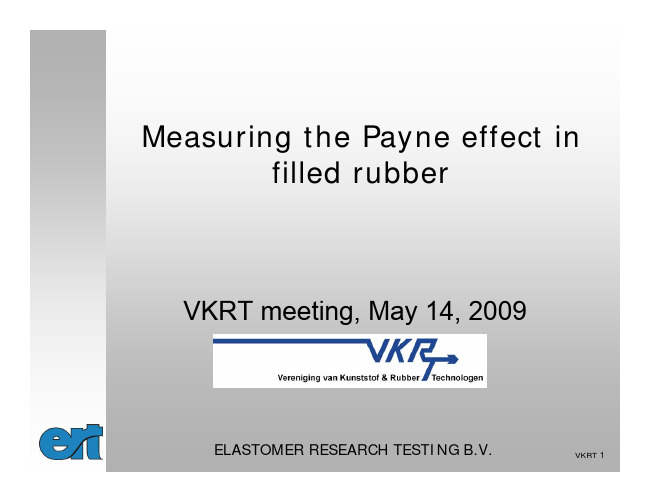
Zeta电位
entity
• The potential at this boundary
is the
ZETA
POTENTIAL
0 Distance from particle surface
Zeta Potential
• The magnitude of the zeta potential gives an indication of the potential stability of the colloidal system
• The higher the ionic strength, the more compressed the double layer becomes
• The valency of the ion will also influence double layer thickness
• A trivalent ion such as Al3+ will compress the double layer to a greater extent compared to a monovalent ion such as Na+
• If all the particles have a large negative or positive zeta potential they will repel each other and there is DISPERSION STABILITY
• If the particles have low zeta potential values then there is no force to prevent the particles coming together and there is DISPERSION INSTABILITY
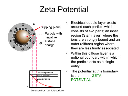
宋义虎+Universal+Contribution+of+Filler+to+Linear+Viscoelasticity+of+Filled+Polymer
Department of Polymer Science and Engineering Key Laboratory of Macromolecular Synthesis and Functionalization of Ministry of Education
Contribution of filler
● Strain amplification effect
Presence of hard and much less deformable filler inclusions in a soft and highly deformable matrix leads to hydrodynamic effects referring to a strain amplification factor Af > 1 Imposing a macroscopic strain to filled polymers Local strain of interstitial fluid = macroscopic strain multiplied by Af
The second class for solid‐like dispersions Using one modulus shift factor plus one frequency shift factor by choosing any concentration at > c as reference concentration Problem: breakdown in high‐ zone due to non‐Newtonian feature of the polymer melts?
精编15.辅料功能性指标对制剂质量的影响_默克资料
Compression to tablets
11 B. Thekedar, June 2012
Potential reduction of 6 additional steps Total cost reduction up to 3 times
What are the best Excipients for DC ?
Mannogem 2080 Mannogem 3215
Polymorph beta beta alpha alpha beta beta beta alpha beta beta beta
appr. BET (m²/g) 3 3 0,6 0,5 0,5 0,4 0,3 0,5 0,3 0,5 0,4
active(s) in the formulation
icity Compressibility Drug loading capacity Friability
Stability Mouthfeel Content uniformity of finished
The influence of functionality parameters on the quality of finished dosages
Dr. Bhushan Thekedar
Field Marketing Manager, Asia – PCS
Overview
High Functional Excipients Excipients for Direct Compression Mannitol for Direct Compression Excipient for Wet Granulation Directly Compressible Magnesium Excipient for Orally Disintegrating Tablets Lubricants with Added Value
涂料化学英语
化学涂料专业英语词汇Abrasion Resistance 抗磨性The ability of a coating to resist degradation due to mechanical wear.Accelerated Weathering 耐候性试验A test designed to simulate but at the same time intensify and accelerate the destructive action of natural outdoor weathering.Acid resistance抗酸性Acrylic Latex丙烯酸乳液:An aqueous dispersion of acrylic resins.Acrylic Resin 丙烯酸树脂A clear resin attained by polymerizing various acrylic monomers either alone or in combination. Adhesion附着力Aggregate骨料Airless Spray 无气喷涂A spraying system in which paint is atomized using high hydraulic pressure rather than compressed air. Alkali碱:An aqueous liquid which has a pH value of between 7 and 14. A base or caustic material. Algae藻菌、霉菌Alligatoring鳄裂Surface imperfections of a coating film having the wrinkled appearance of alligator skin.Ambient Temperature 室温/环境温度Room temperature or the existing temperature of the surroundings.Asphalt沥青:A black resinous material of petroleum origin.Binder:基料The nonvolatile portion of the vehicle of a coating which holds together the pigment particles. Blistering起泡The formation of blisters in paint films by the local loss of adhesion and lifting of the film from the underlying substrate.Blushing发白A film defect which manifests itself as a milky appearance which is generally caused by rapid solvent evaporation or the presence of excessive moisture during the curing process.Brushability涂刷性:The ease of applying a coating by brush.Chalking粉化The formation of a friable powdery coating on the surface of a paint film, generally caused by exposure to ultraviolet radiation resulting in a loss of gloss.Carbonation depth 碳化深度Clear top coat 罩面漆、罩光漆The paint applied to a surface in a single application to form. a film when dry.Coating System 涂料系统A number of coats separately applied, in a predetermined order, at suitable intervals to allow for drying and curing, resulting in a completed job.Color Retention保色性:The ability to retain its original color during weathering or chemical exposure. Corrosion腐蚀The decay, oxidation or deterioration of a substance (steel, concrete, and others) due to interaction with the environment. See also "Rust"Coverage覆盖率Cement 水泥Concrete 混凝土Compressive strength 抗压强度Cracking裂缝:Splitting of a paint film usually as a result of aging.Cross linking 交联The setting up of chemical links between molecular chains to form. a three dimensional network of connected molecules.Density 密度:Mass per unit volume, usually expressed as grams per milliliter or pounds per gallon. Dilute 稀释剂Dew Point 露点The temperature of a surface, at a given ambient temperature and relative humidity, at which condensation of moisture will occur.Delamination 分层Discoloration 变色;污点Dry Time 干燥时间Time allotted for an applied coating film to reach a set stage of cure or hardness.Efflorescence 风化、粉化Water soluble salts, deposited as moisture evaporates, on the exterior of brick or concrete.Elastic弹性Emulsion 乳胶A two phase liquid system in which small droplets of one liquid are immiscible in and are dispersed uniformly throughout a second continuous liquid phase.Enamel 磁漆A term used to characterize a coating which has a glossy smooth finish. A common term for alkyd coatings. Exterior 外墙Fading 失光:Loss of gloss or sheen.Filler 腻子:A compound used to extend or bulk a coating to provide extra body or hiding power.Film 漆膜:A layer of coating or paint.Finish coat 面漆Flash Point 闪点The lowest temperature of a liquid at which sufficient vapor is provided to form. an ignitable mixture when mixed with air.Fungus 真菌类Gloss 光泽Semi-gloss 半光Matt 无光The sheen or ability to reflect light.Gloss Retention 保光性The ability to retain the original sheen during weathering.Glass deterioration 失去光泽Grease 剥落Hardener 硬化剂An activator curing agent, catalyst or cross linking agent.Hiding 遮盖The ability of a coating to obscure the surface to which it is applied.Impact Resistance 抗冲击性The ability to resist deformation or cracking due to a forceful blow. InterionLead-Free Contains, by weight, less than 0.5% lead for industrial products and less than 0.6% lead in consumer products.Lifting 咬底Softening and raising or wrinkling of a previous coat by the application of an additional coat; often caused by coatings containing strong solvents.Mastic 厚浆A term used to describe a heavy bodied coating.Masonry 砖石结构Mil (厚度单位)One one-thousandth of an inch; 0.001 inches. Commonly used to denote coating thickness.Mildew 霉菌A superficial growth of living organic matter produced by fungi in the presence of moisture; results in discoloration and decomposition of the surface.Mosaic 马赛克Moisture contrent Nonvolatile 不挥发The portion of the paint left after the solvent evaporates; solids.Opacity 遮盖力The ability of a paint film to obliterate or hide the color of the surface to which it is applied.Panel board 预制板Peeling 剥落、脱皮A film of paint or coating lifting from the surface due to poor adhesion. Peeling normally applies to large pieces. (See chipping )Permeability 渗透性The degree to which a membrane or coating film will allow the passage or penetration of a liquid or gas. Pigment 颜料A finely ground natural or synthetic, insoluble particle adding color and opacity or corrosion inhibition to a coating film.Pigment/Binder 颜料/基料A ratio of total pigment to binder solids in paint.Plaster 抹灰Polymer 聚合物A substance of molecules which consist of one or more structural units repeated any number of times. Porosity 孔隙度The presence of numerous minute voids in a cured material.Primer 底漆The first coat of paint applied to a surface, formulated to have good bonding, wetting and inhibiting properties.Putty 腻子Relative Humidity 相对湿度The ratio, expressed as a percent, of the quantity of water vapor actually present in the air to the greatest amount possible at a given temperature.Resin 树脂A group of organic materials, either natural or synthetic, which can be molded or dissolved.Repeated warning and coolingRetrofit 翻新Refurbishment 刷新;再磨光Rigid 刚性Roller 滚筒A cylinder covered with lamb's wood, felt, foamed plastics or other materials used for applying paint. Rust 生锈The corrosion of steel or iron is an electrochemical phenomena wherein the base metal reverses to a lower, more stable energy state. If the corrosive environment is water or brine, then the corrosion product formed is commonly known as rust. In the case of other chemicals, such as alkalies or acids, other combinations of iron salts are formed as part of the corrosion product.Sag Resistance 抗流挂The ability of a paint to be applied at proper film thicknesses without sagging.Satin Finish 无光饰面A descriptive term generally referenced to paints with a 60 degree gloss reading between 10 and 40. Shelf Life 贮存期The maximum time interval in which a material may be kept in a usable condition during storage. Skinning (油漆桶内表面)起皮、结皮The formation of a solid membrane on the top of a liquid, caused by partial curing or drying of the coating during storage.Solution 溶液Solvent 溶剂Scrub 擦洗Stain 沾污Suspended 吊篮Scaffolding 吊篮Substrate assessment 基面评估Strip 剥落Solids by Volume 固体含量The percentage of the total volume occupied by nonvolatile compounds.Substrate 基底The surface to be painted.Thixotropic 触变性An adjective which describes full bodied material which undergoes a reduction in viscosity when shaken, stirred or otherwise mechanically disturbed but which readily recovers its original full bodied condition upon standing.Thinners 稀释剂 A liquid (solvent) added to a coating to adjust viscosity.Texture coating 结构漆Undercoat 底漆The coat applied to the surface after preparation and before the application of a finish coat.Vinyl Copolymer 乙烯聚合物A resin produced by copolymerizing vinyl acetate and vinyl chloride.Vapor Transmission Rate 透气性The rate at which moisture passes through a material or coating.Volatile Organic Compounds (VOC)A measure of the total amount of organic compounds evaporating from a coating film, excluding water. Viscosity 粘度Water permeability 水渗透Weather resistant 耐风化Water vapour diffusion 水汽扩散性。
材料功能与信息专业英语复习
材料概论复习题01·Thick sheets of flat glass is made by a special float process. 02·Excessive contents of MgO can lead to destructive(毁灭性的) expansion of hardened concrete.03·As the carbon content of steel increases,steel becomes less ductile(柔软的),i.e.,more brittle.04·Magnesium(镁) is hexagonal-close-packed(六方密堆积) in structure.05·In the case of good glass forming materials like SiO2,GeO2 or B2O3, the required rate of cooling of the melts is remarkably low because the maximum crystallization velocities in these materials are themselves very low.06·Dark color of Portland cement is caused by ferrite phase(铁素体),formation of which must be avoided in a white cement.07· In a body-centred cell,there are two particles per elementary cell. 08·Fracture toughness(断裂韧性) is a generic term for measures of resistance to extension of a crack.09·Anisotropy(各向异性) of properties is mainly observed in monocrystalline(单晶) solids.10· Elastomers(橡胶) are the group of polymers that can easily undergo very11· The favorable characteristic of graphite is best lubricity(润滑性). 12·Stiffness(刚度) is expressed by the modulus of elasticity(弹性),also called Young’s modulus.13·When a liquid id=s cooled from a high temperature to its melting temperature,(Tm),it generally solidifies to a crystalline product.14·There are four particles per elementary cell in a face-centred cell. 15·When carbon is mostly in the form of graphite spheroids(球状石墨) and is produced during solidification by inoculating(对金属溶液进行孕育处理) the cast iron with an element such as magnesium while it is still in the ladle(铸勺),the cast iron exhibits very ductile property.16·Titanium is used in high-speed aircraft for its high strength at high temperatures.17·Magnesium is the lightest of all structural metals.18·There are four main aspects materials science and technology: synthesis, manufacturing and processing, composition and structure,properties and performance.19·The silica structure is the basic structure for glass and ceramics. 20·Glasses are coloured with added oxides or halides(卤化物) and made to change their colours or become darker on exposure or light or heat. 21·Traditional fabrication techniques of ceramic contain Hydroplastic22·The term bulk density is used in this instance to refer to a ceramic’s porosity and the fact that most ceramics contain both a crystalline and a noncrystalline phase.翻译1·Glass when newly formed, with a perfect surface, is very strong about five times as strong as steel. This may seem strange, but theoretically glass should be very strong because of the nature of its interatomic bonds. In practice the strength is very much less than the theoretical value. One of the main causes of this loss of strength is the presence of surface defects, such as those caused by chemical corrosion or mechanical abrasion. These flaws can be very small but because glass is rigid they act to concentrate any applied stress over only a few interatomic bonds at the apex of the crack. Under these conditions the strong bonds break and fracture occurs.玻璃刚成型时有着完美的表面,强度是钢的5倍,这看起来或许很奇怪,但由于本身原子间价键的性质,玻璃理论强度应该很大,实际强度却比理论强度低很多。
fibers polym
ISSN 1229-9197 (print version)ISSN 1875-0052 (electronic version) Fibers and Polymers 2017, Vol.18, No.1, 22-32Ternary Carboxymethyl Chitosan-hemicellulose-nanosized TiO2 Composite as Effective Adsorbent for Removal of Heavy Metal Contaminants from Water Shuping Wu, Jiarui Kan, Xiangzi Dai, Xiaojuan Shen, Kan Zhang, and Maiyong Zhu*Institute of Polymer Materials, School of Materials Science and Engineering, Jiangsu University,Zhenjiang, Jiangsu 212013, P. R. China(Received September 21, 2016; Revised November 14, 2016; Accepted November 18, 2016)Abstract: A ternary composite consisting of carboxymethyl chitosan, hemicellulose, and nanosized TiO2 (CHNT) wasprepared by incorporating TiO2 nanoparticles into the pre-synthesized carboxymethyl chitosan-hemicellulose polysaccharidenetwork. The microstructure and chemical composition of the obtained CHNT was characterized by TEM, SEM, FTIR, andTGA. The adsorption of some toxic heavy metals including Ni(II), Cd(II), Cu(II), Hg(II), Mn(VII), and Cr(VI), onto the as-prepared CHNT composite was investigated. The effects of pH, temperature and contacting time on the adsorption processwere studied. Results revealed that the CHNT composite exhibited efficient adsorption capacity of the above metal ions fromaqueous solution due to its favorable chelating groups in structure. The adsorption process was best described by the pseudo-second-order kinetic model, while isotherm modeling revealed that the Langmuir equation better described the adsorption onCHNT as compared to Freundlich model. Moreover, the CHNT loaded metal ions can be easily regenerated with EDTA andreused repeatedly up to five cycles. The environmental friendly hybrids were expected to be a promising candidate for futurepractical application in heavy metal contaminated water treatment.Keywords: Carboxymethyl chitosan, Hemicellulose, TiO2, Adsorbent, Heavy metalIntroductionEnvironmental contamination by hazardous pollutants is a widespread and increasingly serious problem around the world owing to its long term risk to ecosystems and humans. Among various contaminants, heavy metals undoubtedly can have toxic effect on plants, animals and humans [1]. Therefore, it is essential to develop efficient method to remove undesirable metals from water resources. Nowadays, many techniques including chemical precipitation, ion exchange, coagulation, electrodeposition, solvent extraction, ultrafiltration, and reverse osmosis [2-4], have been developed for the elimination of heavy metal ions. Nevertheless, these methods are limited for wide application either for too high cost or for low efficiency and complex operation processes. Another disadvantage of these methods is the formation of sludge, requiring the additional processes of disposal and confinement. Adsorption technique is considered as a suitable and promising method to remove heavy metals from wastewater due to its flexible operation, high efficiency and low cost. Numerous materials such as activated carbon [5], polymer resin [6], porous silica [7], and so on, are developed as adsorbents for removal of heavy metal contaminants. Unfortunately, the uptake capacities of these materials are low. Meanwhile, they usually remove only a few special species of contaminants. Thus, exploiting novel adsorbent materials with higher adsorption capacities to capture a range of pollutants has attracted increasing interest in recent years.As a naturally occurring biopolymer from crustacean and fungal biomass, chitosan has been received considerable attention for its capability of chemically or physically adsorbing various metal ions [8-12]. It possesses a high ratio of hydroxyl group and amine group, making it conductive to the introduction of new functional groups. These active groups make chitosan efficient in the adsorption of metal ions through coordination or ion-exchange. However, chitosan has few drawbacks such as acidic solubility and low selectivity toward highly toxic heavy metals, which limit the application of chitosan as effective sorbent. So it is desirable to modify chitosan through the introduction of new complexation groups for enhanced its adsorption performance [13-17]. The carboxymethylation of chitosan is regarded as a good chemical modification technique to improve its specificity and capacities toward metal ions [18-21]. Carboxymethyl chitosan (CMC) has many reactive functional groups such as amino group, carboxyl group and hydroxyl group, can reinforce the adsorption selectivity by chelating with metal ions. In spite of its multifunction, the application potential of CMC as sorbent has not been fully commercial development due to water-solube. So chemical cross-linking would provide the potential for regeneration and reuse of adsorbent based on CMC.H emicelluloses (H Cs) are branched biopolymers of low molecular weight with a degree of polymerization in the range of 80-450, which account for 25-35% of lignocellulosic biomass and are the second most abundant polysaccharides after cellulose [22]. HC has abundant hemiacetal hydroxyl groups, which can react with the amino groups of chitosan or chitosan derivatives to form Schiff base compounds via Maillard reaction [23-25]. In addition, Schiff base compounds have the ability to form selective stable complex with heavy*Corresponding author: maiyongzhu@DOI 10.1007/s12221-017-6928-y22CHNT for Removal of Heavy Metals Fibers and Polymers 2017, Vol.18, No.123metals [26-28]. Therefore, cross-linked copolymerization between HC and CMC would open new channels for their exploitation and utilization. Meanwhile, inorganic particles, such as clay [29], diatomite [30], Al2O3 [31], SiO2 [32], Fe3O4 [33], and TiO2 [34,35], have been introduced into the molecular network of polymer materials and can be effective on improving the adsorption performance of adsorbents [6, 36]. Among them, nanosized titanium oxide (TiO2) has been received more attention due to its physical and chemical stability as well as high surface area. TiO2 as a nanofiller can effectively improve the three dimensional molecular network and increase the surface area for metal adsorption. Aliabadi et al. developed the chitosan/TiO2 composite nanofibrous adsorbents for adsorptive removal of Cu(II) and Pb(II). They noted that adsorbents increased the metal ion uptake ability and showed a sign of selectivity in order of Cu(II) > Pb(II) [37]. Keshtkar et al. reported a polyacrylonitrile-TiO2 nanofiber adsorbent fabricated by electrospinning is effective for the removal of Th(IV), Ni(II) and Fe(II), and the nanofiber adsorbent possesses large surface area, desired mechanical strength, and chemical stability [38]. Mahdavi observed that TiO2 nanoparticles modified with humic acid as adsorbents can efficiently remove Cd(II), Cu(II) and Ni(II) [39]. Although the cross-linked/inorganic hybrids have significantly improved the adsorption performance and stability of absorbents, most of the chemical cross-link reagents are expensive, toxic and difficult to prepare, disadvantageous to the broad application. It is necessary to further develop or improve CMC-based adsorbent material that is efficient, eco-friendly, and sustainable.Thus, in this study, a facile method was used to synthesize high performance ternary composite composed of CMC, HC and nanosized TiO2. The morphology and structure of the CH NT were investigated and the adsorption capacities of various heavy metals including Ni(II), Cd(II), Cu(II), Mn(VII), H g(II) and Cr(VI) were evaluated. This work could provide some basic information for the treatment of actual wastewater.ExperimentalMaterialsHC was purchased from Shanghai Hanhong Ltd. (China). Titanium oxide nanopowder (Degussa P25) and sodium dodecyl sulfate (SDS) were purchased from Sigma-Aldrich. CMC and the other chemicals used were of analytical grade obtained from Sinopharm Chemical Reagent Co. Ltd. All aqueous solutions were prepared using purified water with a resistance of 18.2 MΩ·cm.Preparation of CHNT0.04 g nanosized TiO2 powder was added into 50 m l 2 % (v/v) glacial acetic acid containing 56 mg SDS and stirred for 1 h at room temperature. 1.5 g CMC was dissolved into the above solution while maintaining stirring for 4 h with ultrasonic treatment for 15 min at half hour intervals. H C (6.0 g) was dissolved into the suspensions and refluxed under oil bath at 100o C for 2 h to obtain a hydrogel. Then, the hydrogel was heated in drying oven for complete crossing curing at 40o C under atmospheric conditions for 7h and washed with purified water several times to remove the redundant acetic acid. The products was finally freeze-dried for 24 h at -50o C.CharacterizationFTIR spectra of the samples were recorded with KBr discs in the range of 4000-400 cm-1 on Nicolet-170 SX spectro-photometer. The morphology of TiO2 nanoparticles and CHNT on carbon-coated grids was observed by JEM-2100 (HR) transmission electron microscope (TEM). The fracture section of the CHNT was observed using scanning electron microscopy (SEM, H itachi X-650 microscope, Japan). Thermogravimetric analysis (TGA) of the sample was carried out on Pris TGA linked to a Pyris diamond TA Lab System (Perkin-Elmer Co., USA) at a heating rate of 10 K min-1 from 30 to 600o C under a nitrogen atmosphere. The specific surface area of CHNT was investigated by Brunauer-Emmett-Teller (BET) nitrogen sorption-desorption measurement (Micromeritics ASAP2020, USA). Porosities of the CHNT were determined via a modified liquid replacement method [40,41]. The CHNT was permeated with ethanol completely through repeated cycles of vacuum and air charge. The weights of the CHNT at equilibrium, swelling (w2) and dry states (w1) were measured. The porosity of the CHNT, Ф, was calculated from the weight difference between dry and wet samples according to equation (1).(1) where ρethanol and ρCHNT were the density of ethanol and CXTH, respectively.Adsorption StudiesThe adsorption capacities of CH NT for Ni(II), Cd(II), Cu(II), Mn(VII), H g(II) and Cr(VI) were investigated in batch experiments using Atomic Absorption Spectrophotometer (AAS, TAS-990F, China). The effect of pH on the adsorption were carried out at pH 2.0, 4.0 and 6.0 with equilibration for 7 h. Effect of contact time was conducted by placing 0.1 g CHNT in a flask containing 100 m l metal ions (100 mg/l) solution at pH 4.0 for metal ions. The thermodynamic experiments were performed at the solution temperatures of 298 K, 308 K and 318 K, respectively. The adsorption isotherm experiments were performed by adding 0.1 g CHNT into conical flasks containing 100 m l with different heavy metals concentrations (10-600 mg/l) under 100 rpm shaking at 298 K for 7 h. The absolute amount adsorbed of metal ions were calculated by the following equations:Φw2w1/ρethanol–w2w1/ρethanol w2/ρCHNT+–------------------------------------------------------------=24Fibers and Polymers 2017, Vol.18, No.1Shuping Wu et al.(2)where q e was the amount of metal ions adsorbed per unit amount of CH NT (mg/g); C 0 and C e were the initial concentrations of metal ions and the final or equilibrium concentrations of metal ions, respectively (mg/m l ); V was the volume of metal ions solution (m l ), and W was theweight of CHNT (g).Regeneration of CHNTA 0.1 g sample of CHNT was contacted with 100 m l of 100 mg/l metal ions solution, and the mixture was shaken for 7 h. The CH NT loaded with metal ions was separated by filtration and rinsed with deionized water to remove the unabsorbed metal ions. Then, the resin was treated with 20m l of 0.1 M EDTA solution for 2 h [42,43]. Five cycles of consecutive adsorption-desorption-regeneration were carried out to validate the reusability of CH NT. The desorption percentage (D) was calculated as follow:(3)where C EDTA was the metal ion desorbed to the EDTA solution (mg/l ) and C ad was the metal ion adsorbed onto the CHNT (mg/l ).Results and DiscussionStructure of CHNTThe schematic representation for the preparation of the CH NT was illustrated in Figure 1. As we know, sodium dodecyl sulfate (SDS) is an amphipathic molecule containing hydrophilic moiety (head group) and hydrophobic moiety (tail group). At a specific concentration, SDS can form micelles by self-assembly. As shown in Figure 1(a), the formation mechanism of SDS-TiO 2 can be considered that the SDS molecules connect with the TiO 2 substance by hydrophilic force on the head and micellization by hydrophobicq e C 0C e –()V W------------------------=D C EDTA C ad -------------⎝⎠⎛⎞100%×=Figure 2. Microelectronic spectroscope images of CHNT. (a-c) TEM images of pure nanosized TiO 2 (a), CHNT without SDS (b), andCHNT modified by SDS (c). (d-f) Cross-sectional SEM images of CHNT with different magnification corresponding to the picture (c).Figure 1. (a) The formation mechanism of SDS-TiO 2, and (b)schematic illustration for the preparation of CHNT.CHNT for Removal of Heavy Metals Fibers and Polymers 2017, Vol.18, No.125force on the tail [44,45]. The combination of surfactant and inorganic substance allows the construction of hierarchical porous architectures [46]. The amine groups of CMC were crosslinked with H C via Schiff base, and created the network structure of the resin (Figure 1(b)).The SDS surfactant was used to improve dispersibility of TiO 2 in composite. Figure 2 displayed the microelectronic spectroscope images of nanosized TiO 2 and CH NT. As shown, the nanoTiO 2 was in spherical shape and the diameter lay between 15-35 nm (Figure 2(a)). The dispersion stability of the TiO 2 nanoparticles in the polymer matrix is important to improve the 3D network and surface area of CHNT for metal adsorption. After incorporated into the polymer matrix, the TiO 2 nanoparticles without modification by SDS aggregated more significantly (Figure 2(b)). In the presence of SDS, the surfactant molecules were adsorbed on the TiO 2surface and dispersed TiO 2 nanoparticles homogeneously (Figure 2(c)). Figure 2(d)-(f) showed typical SEM image of CH NT. It was noted that CH NT exhibited highly porous structure, indicating that the macrostructured materials with macropore shapes could be synthesized by self-assembly ofsurfactant molecules on the surface of TiO 2 to form surface aggregates [46].In addition, the surface of CH NT was very smooth,indicating the nanoTiO 2 was incorporated into the network of polymer matrix and were benefit for improving the mechanism stability. Figure 3(a) shows the nitrogen adsorption-desorption isotherm of CHNT. The isotherm patterns exhibited a type H3 hysteresis loop according to the IUP AC classification [47], indicating the existence of abundant pores. The BET specific surface areas were determined to be 430 m 2/g. As shown in Figure 3(b), the porosity of CHNT increased with the increase of the content of TiO 2 and reached the maximum 90 % when the weight ratio of TiO 2 to the polymer matrix was 1:0.04.Figure 4 shows the FTIR spectra of HC, CMC and CHNT.In the H C spectrum (Figure 4(a)), several characteristic peaks were observed. The peak at 897 cm -1 can be attributed to the characteristic β-gylcosidic linkage between the sugar units. The broad peak at 1043 cm -1 can be assigned to the stretching and bending vibration of C-O, C-C, and C-OH [25]. The spectrum of CMC (Figure 4(b)) showed, a strong peak at 1415 cm -1 could be assigned to the symmetrical stretching vibration of carboxyl group. The asymmetrical stretching vibration of carboxyl group at around 1652 cm -1 is overlapped with a strong band of N-H stretch at 1629 cm -1.The absorption peak at 1070 cm -1 was assigned to the C-O stretch of secondary hydroxyl group [48,49]. Compared with CMC, CH NT showed a new peak at 1644 cm -1, which is attributed to the C=N stretching vibration derived from the Schiff base [50,51]. In addition, the appearance of the characteristic peaks of hemicellulose confirmed that HC and CMC were successfully combined by thermal cross-linking. The thermal properties of H C, CMC and CH NT were studied by TGA as shown in Figure 5. The weight loss of CHNT in the initial thermal treatment (below 200 o C) was attributed to the loss of SDS, which may not be firmly interacted with nanoTiO 2. At 50% weight loss, thedecomposition temperature of HC, CMC and CHNT was atFigure 3. Nitrogen adsorption-desorption isotherm of CHNT (a),and porosity of CHNT as a function of nanoTiO 2contents (b).Figure 4. FT-IR spectra of HC (a), CMC (b), and CHNT (c).26Fibers and Polymers 2017, Vol.18, No.1Shuping Wu et al.294, 316, and 326 o C, respectively. These results indicated that the nanoTiO 2 was excellent nanofiller for improving the thermal stability property of polymer matrix.Effect of pHIt is well-known that pH is an important parameter controlling the adsorption process. For most biosorption systems, the uptake of heavy metal ions from aqueous solutions using biomass materials as biosorbent occurs with maximum efficiency in a pH range between 4.0 and 6.0. In this pH range, most of heavy metals exist in solutions predominantly as free metal ions, and the ionization degree of functional groups from adsorbent surface is higher enough to allow the electrostatic interactions. As shown in Figure 6, it is obvious that the uptake capacities significantly as pH increases from 2.0 to 4.0, whereas, the adsorption amount decreases at pH from 4.0 to 6.0. This phenomenon can be explained that the ion-exchange interactions between the CHNT and metal ions. At low pH, the protonation of theamino groups results in the reduction of number of binding sites available for the adsorption of metal ions. H owever,with the increase of pH to a certain value, hydroxyl coordination effects play a major role on the process of adsorption, which leads to the weakening of the ion-exchange interactions. In order to ensure quantitative adsorption and avoid the coordination of hydroxyl, the optimum pH of metallic solution is chosen as 4.0 for further studies.Adsorption of Heavy Metal Ions on CHNTTo evaluate the adsorptive potential of the as-prepared CHNT, the removal of heavy metals such as Ni(II), Cd(II),Cu(II), Mn(VII), Hg(II) and Cr(VI) was studied under mild conditions. We studied the effect of the exposure time on the adsorption of these ions. Figure 7 shows the variations of the amount of adsorbed heavy metal ions onto CH NT over contact time. According to the results, the adsorbed amount of metal ions was improved by increasing the exposure time.The uptake amount of heavy metal ions onto the CH NT obeyed the orders: Ni(II)>Cd(II)>Cu(II)>Mn(VII)>H g(II)>Cr(VI). The adsorption capacities of CH NT for Ni(II),Cd(II), Cu(II), Mn(VII), Hg(II) and Cr(VI) were 32.2, 27.6,13.5, 9.4, 4.8 and 4.3 mg/g, respectively.The adsorption mechanism of metal ions by CHNT was investigated using FTIR spectroscopy in the range of 400-4000 cm -1. It can be seen from Figure 8 that the FTIR spectra of CHNT after adsorption of heavy metals exhibited many alterations from that of CHNT before adsorption. Significant changes in the FTIR spectra were observed at the wavenumber between 600 and 1200 cm -1, which may be assigned to the stretching vibration of N-Metal and O-Metal [25,52]. The stretching of carboxyl group was shifted to a lower frequency,thereby indicating complexation through the carboxyl group to metal ions [53,54]. The wide absorption band at 3448 cm -1corresponding to the stretch vibration of O-H was shifting toFigure 5.TGA curves of HC, CMC and CHNT.Figure 6. Effect of pH on the uptake of heavy metal ions by CHNT (initial concentration of metal ions 100 mg/l ; CHNT, 1 g/l ;contact time 7 h; shaking rate 100 rpm; 298 K).Figure 7. Effect of contact time on the uptake of metal ions by CHNT (initial concentration of metal ions 100 mg/l ; CHNT, 1 g/l ;pH 4.0; shaking rate 100 rpm; 298 K).CHNT for Removal of Heavy Metals Fibers and Polymers 2017, Vol.18, No.127the lower wavenumber. Meanwhile, it seemed that the bands at 1629 and 1043 cm -1 assigned to N-H and C-O stretch after the adsorption process shifted to higher frequency. The intensity decrease of C=N and -NH stretching in FTIR spectra suggests the interaction of metal ions with Schiff base. This results indicated that many reactive functional groups such as hydroxyl, amino and carboxyl groups were enhancing the chelating ability with metal ions.Adsorption KineticsTo perform the adsorption process with larger scale, the kinetic parameters and adsorption characteristics of CHNT should be determined. For this reason, Lagergren’s pseudo first-order and pseudo second-order equations were applied to model the adsorption/time data obtained.The pseudo-first-order equation was represented by [55](4)The pseudo-second-order equation can be expressed as [56](5)where q e and q t (mg/g) are the amount of heavy metal ions adsorbed on CH NT at equilibrium and at a given time t ,respectively; k 1 is rate constant (h -1) of pseudo first-order kinetic model for adsorption; k 2 (g/(mg·h)) is the adsorption rate constant of pseudo second-order kinetic model.The plots of ln(q e − q t ) versus t and t /q t versus t are shown in Figure 9, giving k 1, k 2, q e , and R 2 for the Lagergren adsorption and second-order rate equation. Based on the obtained correlation coefficients, the pseudo second-order kinetic equation was feasible to describe the adsorption process, as shown that the correlation coefficients for thefirst-order kinetic model (Figure 9(a)) are lower than the second-order model fits (Figure 9(b)). The calculated results were listed in Table 1. The correlation coefficients for the second-order kinetic model were almost equal to 1 (0.9789-0.9998) for almost all the cases. Also, the calculated q e,cal ,values also agreed with the experimental data q e,exp .The intraparticle diffusion model was further used to identify the importance of diffusion during adsorption process of heavy metal ions onto CH NT composite. The intraparticle diffusion equation most widely applied for sorption system was proposed by Weber and Morris as following [25]:(6)where k d is the intraparticle diffusion rate constant (mg/(g·min 1/2), C is the intercept (mg/g). According to equation (6), a plot of q t versus t 1/2 should be a straight line when adsorption mechanism follows the intraparticle diffusionln q e q t –()ln q e k 1t–=t q t ---1k 2q e 2---------1q e ----⎝⎠⎛⎞t +=q t k d t1/2C +=Figure 8. FT-IR spectra of CHNT before and after adsorption of metal ions. (a) CHNT, (b) CHNT-Cr(VI), (c) CHNT-Cu(II), (d)CHNT-Ni(II), (e) CHNT-Hg(II), (f) CHNT-Cd(II), and (g) CHNT-Mn(VII).Figure 9. Lagergren adsorption diagram of heavy metals on CHNT using different models: pseudo first-order equation (a) and pseudo second-order equation (b) (initial concentration of metal ions 100 mg/l ; CHNT, 1 g/l ; pH 4.0; shaking rate 100 rpm; 298 K).28Fibers and Polymers 2017, Vol.18, No.1Shuping Wu et al.process. If the plot passes through the origin, then intraparticle diffusion is the rate-controlling step. In the case where the lines have a nonzero intercept, external film and intraparticle diffusion contribute to the actual adsorption process. On the other hand, such plots may present multilinearity, which indicates that two or more steps occur in the sorption process. In this study, the intraparticle diffusion plots of various heavy metals adsorbed onto CHNT were displayed in Figure 10. It can be seen that the plots clearly exhibit two distinguishable intercepting lines, a relatively fast increasing step at beginning, followed by a slow increasing and a stagnate afterwards, indicating that the adsorption of heavy metal ions on the adsorbent is a multi-step process. Furthermore, the linear plots at each concentration did not pass through the origin, suggesting that the intraparticle diffusion is not only the rate-controlling step, but that other processes may control the rate of adsorption. The adsorption process was controlled by a multi-step process, involving adsorption on the external surface and diffusion to the surface of the adsorbent.Adsorption IsothermsTo further understand the adsorption process, the adsorption equilibrium of the CH NT is fitted with the Langmuir and Freundlich isotherms. The correlation of equilibrium data using either a theoretical or empirical equation is essential for the adsorption interpretation and prediction of the extent of adsorption. Generally, the Langmuir model, which is represented by equation (7), is based on the assumption of a structurally homogeneous adsorbent where all adsorption sites are identical and energetically equivalent [57]. WhileTable 1. Kinetic parameters for heavy metal ions adsorption by CHNTMetal ion q e,exp (mg/g)Pseudo-first-order model Pseudo-second-order modelk1 (h-1)q e,cal (mg/g)R2k2 (g/(mg·h))q e,cal (mg/g)R2Ni(II)32.50.561870.00.94570.020735.10.9958 Cd(II)27.60.56590.00.88410.016232.40.9789 Cu(II)13.80.628730.30.95410.084014.80.9927 Mn(VII)9.370.542720.00.93940.12659.920.9809 Hg(II) 4.690.548412.00.91680.6880 4.790.9998Cr(VI) 4.000.873511.90.88470.1630 4.380.9958Figure 10. The intraparticle diffusion model for heavy metal ions adsorption by CHNT (initial concentration of metal ions 100 mg/l; CHNT, 1 g/l; pH 4.0; shaking rate 100 rpm; 298 K).Figure 11. Langmuir (a) and Freundlich (b) plots for theadsorption of heavy metal ions onto CHNT (metals concentrations10-600 mg/l; CHNT, 1 g/l; contact time 7 h; pH 4.0; shaking rate100 rpm; 298 K).CHNT for Removal of Heavy Metals Fibers and Polymers 2017, Vol.18, No.129the Freundlich isotherm model, represented by equation (8),is widely used to describe the adsorption on heterogeneous surfaces [58]. Therefore, the adsorption isotherm analysis could provide qualitative information on the capacity of the adsorbent and the nature of the solute-surface interaction.(7)(8)where q e is the amount of heavy metal ions adsorbed at equilibrium (mg/g), C e is the liquid-phase heavy metal ion concentration at equilibrium (mg/l ), constant K L is the Langmuir isotherm constant (l /mg), q max is related to the Langmuir monolayer adsorption capacity (mg/g), K F is the Freunlich isotherm constant (mg/g), and n is the heterogeneity factor.The adsorption of various heavy metals onto CHNT fitted to the Langmuir (plotting C e /q e vs C e ) and Freundlich (plotting ln q e vs ln C e ) isotherm models are shown in Figure 11. As shown in Figure 11(a), the Langmuir isotherm showed a straight line with high correlation coefficient,which indicated that the adsorption of heavy metals onto the CH NT fitted the Langmuir isotherm reasonably well.However, the experimental data do not fit very well to the Freundlich isotherm model, and there is a great difference between the Freundlich plots and the trend lines (Figure 11(b)). A value of 1/n below 1 reveals a normal Langmuir isotherm while 1/n above 1 is an indicative of cooperative adsorption. These results demonstrate that the surface of CHNT is homogeneous with the adsorption mechanism of monolayer uptake. The corresponding parameters for all of the samples obtained from the linear plots of Langmuir and Freundlich isotherm models are listed in Table 2. It can be seen that the linear coefficients of determination (R 2) for the Freundlich isotherm model are lower than 0.95 except Ni(II), which indicate that this model does not describe very well the adsorption processes of the CHNT for these heavy metals. In the case of the Langmuir isotherm model, it can be found from Table 2 that R 2 values are higher than 0.95.Thus, it can be easily concluded that the Langmuir model is much better to describe the adsorption of heavy metal ions onto CHNT than the Freundlich model. This indicates that a monolayer coverage of heavy metal ions has formed on the surface of CH NT. The maximum adsorption capacities ofC e q e -----1K L q max ---------------⎝⎠⎛⎞C e q max ---------⎝⎠⎛⎞+=ln q e ln K F 1n --⎝⎠⎛⎞ln C e+=Table 2. Langmuir and Freundlich isotherm parameters for the metal ions adsorption onto CHNT Metal ion Langmuir modelFreundlich modelK L (l /mg)q m (mg/g)R 2K F (mg/g)n R 2Ni(II)0.0111370.40.983513.0 1.740.9522Cd(II)0.0097555.60.9956 6.9 1.270.9298Cu(II)0.0254526.30.969021.3 1.510.9432Mn(VII)0.001918.60.99200.2 1.140.9454Hg(II)0.004229.90.96600.4 1.570.9299Cr(VI)0.031232.10.99202.22.270.9104Table 3. Comparison of the maximum adsorption capacities with different adsorbents for various metal ionsAdsorbentMaximum adsorption capacity (mg/g)Reference Ni(II)Cd(II)Cu(II)Mn(VII)Hg(II)Cr(VI)Banana peel 1.684----59Coal bottom ash--13.44 2.34--60Coconut shells carbon 83.16-86.0175.6561Ipomea batatas carbon---23.4--62Poly(vinyl alcohol)/silica composites ----113.6-63PET fibers--96.81-120.02-64Polypyrrole (PPy)/SBA-15----200-65Bengal gram husk -8.589.70---66Elaeagnus angustifolia 1.97 2.42---7.1967Carica papaya seeds 5.58---- 5.8568Ficus glomerata -----23.169CHNT370.4555.6526.318.6 29.932.1Present study。
- 1、下载文档前请自行甄别文档内容的完整性,平台不提供额外的编辑、内容补充、找答案等附加服务。
- 2、"仅部分预览"的文档,不可在线预览部分如存在完整性等问题,可反馈申请退款(可完整预览的文档不适用该条件!)。
- 3、如文档侵犯您的权益,请联系客服反馈,我们会尽快为您处理(人工客服工作时间:9:00-18:30)。
ISSN 1063-7842, Technical Physics, 2007, Vol. 52, No. 6, pp. 812–815. © Pleiades Publishing, Ltd., 2007.Original Russian Text © V.I. Vettegren, A.Ya. Bashkarev, M.A. Suslov, 2007, published in Zhurnal Tekhnichesko œ Fiziki, 2007, Vol. 77, No. 6, pp. 135–138.
812 INTRODUCTIONFillers, which substantially change the strength ofpolymers, are introduced into polymers to vary theirmechanical, thermophysical, and tribological proper-ties. Upon the introduction of fillers, the strength mayboth increase and decrease. To reveal the causes of thisphenomenon, we study the dependence of the compos-ite strength on the shape of fillers (powders and fiberfragments).
EXPERIMENTALThe matrix was poly(2,6-dimethyl-1,4-phenyle-neoxide) (PDPO), and the fillers were copper and poly-tetrafluoroethylene (PTPE) particles ≈ 1 µ m in diame-ter, aluminum particles ≈ 0.1 µ m in diameter, fragmentsof carbon and glass fibers ≈ 6 µ m in diameter, and frag-ments of polyamidobenzimidazole (PABI) fiber ≈ 15 µ m in diameter. The length of the fragments was ≈ 3 mm.
These composites are of interest, since they offer alow friction coefficient, high wear resistance, and goodworkability. Because of this, they are widely used fordesigning dry-friction units in precision machine build-ing [1–4].
To provide a strong adhesion to the matrix, the fillerswere subjected to a special thermochemical treatment
[3, 4]. Then, PDPO powder was mixed with them in avibrating mill and pressurized at a temperature of ≈ 520 K for several hours.
The samples to be studied have the form of bars55 mm long with width b = 5 mm and thickness h =4 mm. The bending strength was measured at strain rate
≈ 10 MPa/s on an FM-1000 strength testingmachine. The time to failure was ≈ 40 s. The distancebetween the supports was l = 40 mm. Fracture stress σ f
was calculated by the well-known formula [5]
CAUSES OF COMPOSITE STRENGTH VARIATION UPON THE INTRODUCTION OF FILLERS
We found that the composite strength decreasesafter the introduction of the powders and increases afterthe introduction of the fiber fragments (Fig. 1a).
At given temperature T , the dependence of time tofailure τ of solids [6–11] (in particular, filled compos-ites [12]) on tensile stress σ is known to be described by
σ˙σf3Pl2bh2-----------.=
Effect of the Shape of Filler Particles on the Strength of a Polymer Composite
V. I. Vettegren a , A. Ya. Bashkarev b , and M. A. Suslov c a Ioffe Physicotechnical Institute, Russian Academy of Sciences,
Politekhnicheskaya ul. 26, St. Petersburg, 194021 Russiae-mail: Victor.Vettegren@mail.ioffe.ru b St. Petersburg State Polytechnical University,
Politekhnicheskaya ul. 29, St. Petersburg, 195251 Russia c Central Research Institute of Materials, St. Petersburg, 191014 Russia
Received September 20, 2006
Abstract —When metallic or polymeric powder fillers are introduced into poly(2,6-dimethyl-1,4-phenyleneox-ide) (PDPO), the strength of the filled composites is found to decrease, while when glass or polymeric fiberfragments are introduced into PDPO, the effect is reverse. The fracture activation energy of the composites isshown to coincide with the fracture activation energy of PDPO. The variation of the strength is caused by thedependence of structure-sensitive parameter γ of the matrix on the concentration and shape of filler particles.On the one hand, filler particles are stress concentrators and their introduction decreases the strength. This effectprevails in the composites filled by spherical particles. On the other hand, when anisotropic particles are intro-duced, matrix molecules are arranged parallel to their axis, which decreases γ and increases the strength. Thiseffect is predominant in the composites filled by fiber fragments.
PACS numbers: 62.20.-x DOI: 10.1134/S1063784207060266
BRIEFCOMMUNICATIONS TECHNICAL PHYSICS Vol. 52 No. 6 2007 EFFECT OF THE SHAPE OF FILLER PARTICLES813 the Zhurkov equation(1)where τ 0 ≈ 10 –13 s, k B is the Boltzmann constant, U 0 isthe fracture activation energy, and γ is the structure-sen-sitive parameter related to overstress coefficient q andfracture activation volume ∆ V by the expressionAs follows from Eq. (1), the introduction of a fillermay change either fracture activation energy U 0 orparameter γ .As was noted above, the composite strength wasdetermined at constant strain rate . To find U 0 and γ under these conditions, we make use of Eq. (1) and theBailey durability criterion [9–11],(2)where t f is time to failure. Since exp ӷ 1, thisexpression can be recast as(3)where σ f is the fracture strength at a constant strain rate.For the samples under study, γ was found to be 0.4–2.2 nm 3 . Therefore, as the temperature varies from 300to 400 K, ln( γτ 0 / k B T ) changes from 29 to 31. Underthese conditions, Eq. (3) can be recast as(4)As follows from Eq. (4), the temperature depen-dence of the strength should be almost linear, whichwas indeed observed for both the PDPO matrix and thecomposites (Fig. 2).The straight lines in Fig. 2 intersect the temperatureaxis (the strength vanishes) at temperature T ∗ . FromEq. (4), we have(5)It was found that, within the limits of experimentalerror, the values of U 0 for all the composites are thesame and coincide with the activation energy of matrixmolecule breaking ( U 0 = 1.1 ± 0.1 eV). Therefore, thefiller causes a change only in structure-sensitive param-eter γ of the matrix. This parameter can be determinedfrom the relationship(6)ττ0