产品英文说明书
产品说明书样本(英文版)

The first summarizeToday,internal sample of liquid dielectric in the oiltank is performed by ISO3170(GB/T4756-1998)?Petrol liquid product handicraft sample law?.It is impossibly to control accurately sample ually the sample will not be exact.Performing personnels will feel tired as usual because of hardwork.When rain or snow,climb oiltank that is a very dangerous job.When getting a sample at top of oiltank,easily volatile and noxious dielectric will injure someones,at one time,it will not be in favour of environment and the medium of oiltank will be polluted by other things from environment.For solving these problem, we have developed 〞The auto control getting sample from oiltank〞that according to ?ISO3170(GB/T4756-1998 criterion?,it has achieved that liquid sample at different level of oiltank will be sampled. The machine operation is very simply、very accurate、excellently repeated,it’s structure is simple and it will be install very easily. It will not pollute the environment too. The sample machine has been awarded nationalpatent and the second prize of the sino petrol & chemical industry automation vocation 2021 year. The auto control getting sample from oiltank , it’s structure is sample, it will be install very easily、it’s operation i s very simply、very accurate and it will not pollute the environment. At present, it’s technology has been take the lead in the like product.We have gotten by the auto control getting sample from oiltank the patents and the credits that are:( 1 ) The liquid sample devicment from oiltank, the number of parent is . ( 2 ) The liquid sample from oiltank Multilayer frame means expansion of type of zero gravity, the number of parent is( 3 )The sample devicment of Multi-dimensional sampling valve, the number of parent is( 4 )The multichannel two globe valves, the number of parent is( 5 ) The nationalpatent and the second prize of the sino petrol & chemical industry automation vocation 2021 yearPatentee’s declaration:About the patents of oil tank sampler:( 1 ) The liquid sample devicment from oiltank, the number of parent is . ( 2 ) The liquid sample from oiltank Multilayer frame means expansion of type of zero gravity, the number of parent is( 3 )The sample devicment of Multi-dimensional sampling valve, the number of parent is( 4 )The multichannel two globe valves, the number of parent isThe 4 items’s using right has been awarded to Lan zhou GuKe chemical plant & apparatus Co.,Ltd by patentee for manufacture and sale. If others will manufacture and sell them ,they will break the law, the patentee will inquire their responsibility of law and call for economics compensation.The patentee’s signature:The designsketch in fact:The second sampler technology parameter:item parameterCarried standard ISO3170 GB/T 4756-1998?The petroleum liquid handicraft sample method?Usual sample dot distribution setting Upper sample、middles ample、lower sample、upper middles lowe’s 1:1:1uniform combination sample and bottoms ample、exits samples、upper sample〔reference〕Multilayer framemeans expansionsample allowablehightReaching to the bottom of oiltank is 600-25000mmApplicable medium Gas、kerosene、diesel、solvent oil、naphtha、petroleum aromatics、paraffindestillat、residual oil、heavy oil、crude oil、bitumen and so onSample hight locationerror±20mmOiltank connecting spool installional location Reach to the bottom of oiltank is 500-800mm〔convenient hight for sample operation〕Handpump GearpumpSpeed increasing ratio 3:1FlowDeliverylift 50mDisplacement pumpSpeed increasing ratio 1:1FlowDeliverylift 85mPneumatic pump GearpumpCompressed air pressureCompressed air maxlossm3/minSpeed reducingratio30:1Pneumatic motor torque 55N-mPneumatic pump 32mThe third type of sampleThe fourth applicable rangeThe self-tuning oil tank sampler is applicable to liquid medium of oiltank in the petroleum and chemical industry and so on.(for example:gas、kerosene、diesel、white oil、naphtha、crude oil、all kinds of residuum、slops、asphalt、petroleum aromatics、various solvent、thick vitriol、organic acid、lye、beer and so on)’s upper sample、middles ample、lower sample、upper middles lowe’s 1:1:1 uniform combination sample and bottoms ample、exits samples、upper sample and so on.Setting sample at the especial location by users’s require.Can setting 9 point for maxize.The fiveth The self-tuning oil tank sampler’s characteristic and virtue 1.Accurate sample locationThe sampler uses the patent technology〞The liquid sample from oiltank Multilayer frame means expansion of type of zero gravity, the number of parent is 〞.We establish the database of multilayer frame means expansion manufacture parameter by more and more test. We can assure that our multilayer frame means expansion can conquer connatural weak point that can not go up and down in ratio of equality by others. Assure every sample connection that been set in multilayer frame means expansion can automatically go up and down in ratio of equality with liquid level, to let it to truely get upper sample、middles ample、lower sample、upper middles lowe’s 1:1:1 uniform combination sample. If multilayer frame means expansion can go up and down in ratio of equality that will decide every connection’s definition of sample.For the drawing-1:the drawing-12. Independence ofsample mediumThe sampler uses thepatent technology〞Thesample devicment of Multi-dimensional sampling valve, the number of parent is 〞that is independent shunting plant of multilayer sample in the valve. It can take sample of every location independently shunt to lofting valve and can mix upper sample、middles ample、lower sample by the rate of 1:1:1 and take it to lofting valve, sample personnel can get every independent sample and 1:1:1 uniform combination sample from lofting valve exit.3、Security and reliabilityA) The self-tuning oil tank sampler uses the patent technology〞The multichannel two globe valves, the number of parent is 〞that can fast cut off the communication of guitar pipe and pipe of outside, make sure that medium of oiltank will not leak out.The globe valves’s button run reliably and accurately, it’s operation is simple and convenientB) The sampler only need be operated on the ground, and operationer need not climb to the top of oiltank to sample. Eliminate the danger of climbing in the rain or snow. Eliminate the danger when getting a sample at top of oiltank,easily volatile and noxious dielectric will injuresomeones. Take humanized and reliable environmental sample come true.4.Reasonable structure and simple operationThe sampler uses the patent technology〞The sample devicment of Multi-dimensional sampling valve, the number of parent is 〞that take multilayer sample oil pipes scientifically and possibly combine into one of circular operation hand-actuated wheel. Operate the rated hand-actuated wheel to choice sample point. Take complex operation process to simple action.For drawing-2Drawing-25.Hes-cling structure and little leaking pointScience and reasonable The self-tuning oil tank sampler structure, Can the DuoGe sampling output line and a circulation return pipe road high oil chips in cluster. Make DuoGe independent sample line compact from a took over, the output to tank through within the operation of the DuoWei sampling valve ,This compact structure tell the DuoGe lofting, thus greatly reducing valve sealing the number of points. In normal conditions using zero leakage .For drawing-3For drawing-36.Sample pipe road has reverse wash function:The self-tuning oil tank sampler take SKC-HF structure circulating pump But through the cycle of the pump valve or reverse rotation oil change realize tank Sample pipe road, reverse through media Thus will CaiYangGuan way or tank sampling injector mesh on the plugging of dirt reverse wash to tanks, at any time to sampling the pipeline the cleaning7.Replacement old way of the operation is simple:The self-tuning oil tank sampler used specially developed for sampling convenient and special two tee lofting valve, Made with a conversion between lofting cycle is very simple, just press the valve for the arrows spin an Angle start after circulating pump can.8.Convenient installation:The sampler can be set up special steam heating device, oil tank external sampler components have straight heat conduction heat tracing of. For drawing-4 Use electric heating, in the valve body sampler exclusively electric tracing band through the heating channel, the heating effect ideal. A heating device can be used for the sampler asphalt, and so easy as the medium tank.For drawing-49. Meet of the medium to samplingThe sampler can be set up special steam heating device, oil tank external sampler omponents have straight heat conduction heat tracing of. Use electric heating, in the valve body sampler exclusively electric tracing band through the heating channel, the heating effect ideal. A heating device can be used for the sampler asphalt, and so easy as the medium tank.The sixth.T he self-tuning the composition of the oil tank samplerThe self-tuning oil tank sampler The composition of the oil tank sampler as shown in figure 5 shows1, extendable frame; 2, float group; 3, circulating pump 【manual pump, pneumatic pump 】; 4, sampling combination tube; 5, sampling distribution device; 6, the integrated oil, a choice of the directional control valve, valve, sample combination distribution on a stop valve, no drop leak lofting valve combination together; 7, operation box; 8, adjustable bearing; under the plane 9, small tube resistance metal hoseFor drawing-5The seventh.working principleThe self-tuning oil tank sampler is through the float group in the expansion set drive tank with oil level within the truss and sample, the upper or lower, middle kind, samples and top samples (optional) sampling mouth all fixed in telescopic rack, telescopic frame in liquid is according to the proportion of sampling, ensure that came out of the position accuracy. The sampling location is determined according to the ISO3170 (GB/T4755 1998) "oil liquid product manual sampling method" regulation of sampling location of the design. For drawing-6 showsFor drawing-6Different sample position of the pipeline is independent sample through sampling combination tube transfer to oil chips, again through the DuoWei reversing valve handwheel control of their respective independent leads to the valve, again by lofting lofting valve control lofting or cycle will turn to cycle the valve, start lofting circulation pump can turn number after the part of the old way of pipeline to the bottom of the tank replacement cycle; And then the valve position to rotate lofting lofting, can get the export of lofting valve in the tank is a position of the sample. Repeat the above。
AUTOMATED EQUIPMENT LLC 产品说明书 P N 291035 英文版
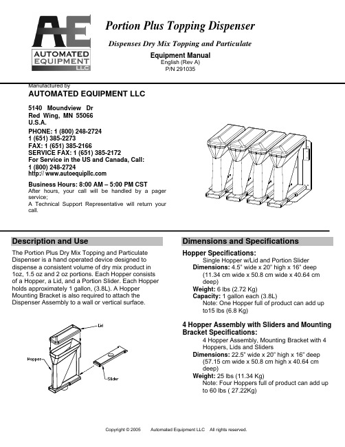
Portion Plus Topping DispenserDispenses Dry Mix Topping and ParticulateEquipment ManualEnglish (Rev A) P/N 291035Manufactured byAUTOMATED EQUIPMENT LLC5140 Moundview Dr Red Wing, MN 55066 U.S.A.PHONE: 1 (800) 248-2724 1 (651) 385-2273FAX: 1 (651) 385-2166SERVICE FAX: 1 (651) 385-2172For Service in the US and Canada, Call: 1 (800) 248-2724http:// Business Hours: 8:00 AM – 5:00 PM CSTAfter hours, your call will be handled by a pager service;A Technical Support Representative will return your call.Description and UseThe Portion Plus Dry Mix Topping and Particulate Dispenser is a hand operated device designed to dispense a consistent volume of dry mix product in 1oz, 1.5 oz and 2 oz portions. Each Hopper consists of a Hopper, a Lid, and a Portion Slider. Each Hopper holds approximately 1 gallon, (3.8L). A Hopper Mounting Bracket is also required to attach the Dispenser Assembly to a wall or vertical surface.Dimensions and SpecificationsHopper Specifications:Single Hopper w/Lid and Portion SliderDimensions: 4.5” wide x 20” high x 16” deep(11.34 cm wide x 50.8 cm wide x 40.64 cm deep)Weight: 6 lbs (2.72 Kg)Capacity: 1 gallon each (3.8L)Note: One Hopper full of product can add up to15 lbs (6.8 Kg)4 Hopper Assembly with Sliders and Mounting Bracket Specifications:4 Hopper Assembly, Mounting Bracket with 4 Hoppers, Lids and SlidersDimensions: 22.5” wide x 20” high x 16” deep(57.15 cm wide x 50.8 cm high x 40.64 cm deep)Weight: 25 lbs (11.34 Kg)Note: Four Hoppers full of product can add up to 60 lbs ( 27.22Kg)CleaningWarranty InformationThe Hopper, Lid, Slide, and Mounting Bracket are warranted to be free from manufacturing defects in material or workmanship for one (1) year. The warranty period commences on the shipping date and applies only to the original purchaser. Except as otherwise provided herein, Automated Equipment LLC, makes no other warranties, expressed or implied, and specifically disclaims any warranty of merchantability or fitness forparticular purpose. Automated Equipment LLC, shall not be liable for any direct, indirect, consequential damages (including damages for loss ofbusiness profits, business interruption, loss of business information and the like) arising out of the use of or inability to use this product. This warranty is void if the product is not functioning correctly due to abuse or neglect by the purchaser, its employees, agents, or other representatives either by breaking, bending, misuse, abuse, dropping, alteration, improper installation or maintenance, or any other form of neglect or improper usage. This warranty does not cover damage to the product caused by natural causes such as lightning, flood, fire, tornadoes, or other acts of God. This warranty is governed by the substantive laws of Minnesota, USA, without giving effect to the conflict of law provisions.• Use water, a soft brush and mild detergent tothoroughly clean all parts of the Dispenser.• Do not use abrasive cleaning pads or cleansers. • Frequent cleaning will prevent food buildup on thesliding parts and ensure proper operation.Warning!• Do not use a dishwasher to clean the Dispensercomponents. Hand wash only.• Do not use excessive force to operate the Sliders. • Dispense dry products only. Do not attempt todispense frozen or liquid products.• Do not attach or hang other material or equipmenton the Mounting Bracket or Hopper Assembly .The information in this manual is subject to change without notice. In no event will Automated Equipment LLC, be liable for technical or editorial omissions made herein; nor for direct, special, incidental, or consequential damages resulting from the furnishing, performance, or use of this material.。
产品说明书中英文对照

3M TM Attest TM 1264/1264PBiological Indicator生物指示剂Product description: The 3M Attest 1264 Biological Indicator (green cap) is designed for monitoring of EO sterilization process.The presence of Bacillus atrophaeus spores is detected by a visual color change (media turns yellow). The yellow color change indicates a sterilization process failure. The final readout of a negative result (media remains green) is made after 48 hours of incubation.产品描述:3M Attest 1264生物指示剂(绿帽)用来监测环氧乙烷灭菌过程。
可通过视觉上的颜色变化(培养基变成黄色)来检测枯草杆菌芽孢是否存在。
如果培养基变成黄色,则表明灭菌过程失败;如果培养基保持绿色不变,经48小时潜伏期后,最终得到阴性结果。
Monitoring frequency: Attest biological indicators should be placed in an appropriate test tray or package, and be used to monitor every load. This presents an appropriate challenge and improves the performance of the sterilization process.监测频率:Attest生物指示剂应放置在适当的测试盘或包装内,以便监测每一个负载。
英文产品说明书

英文产品说明书(总9页) -CAL-FENGHAI.-(YICAI)-Company One1-CAL-本页仅作为文档封面,使用请直接删除Spiral chute1、product descriptionSpiral chute is integrated spiral separator, spiral chute, shaker, centrifugal concentration machine characteristics of the equipment, mining, mineral processing is the best equipment, especially the seaside, riverside, sand beach, the stream of placer mining is more ideal. The product has the advantages of reasonable structure, simple installation, covers an area of small, simple operation, stable ore beneficiation, clear, large processing capacity, high efficiency enrichment ratio high, high recovery rate, reliable operation characteristics. Have weight light, moisture-proof, rust-proof, corrosion resistance, of the feeding quantity and concentration, particle size, quality of volatility adaptability is strong, no noise.2、Separation principleSpiral chute is a membrane flow gravity separation equipment, the selection principle is the use of useful minerals and gangue in proportion, particle size, shape differences, in rotating inclined flow by gravity, centrifugal force, hydrodynamic pressure andfriction force with different groove face, realize the useful minerals and gangue stratification, branch tape sorting. Heavy, coarse granularity, fast sedimentation of particles gradually moved towards the spiral groove inner edge, the proportion of small, fine particle size, particle sedimentation slow gradually moved to the spiral groove edge, gradually banding, culminating in the spiral groove end by cutting ore tank is respectively connected out, to realize separation.3、ApplicationThe sorting equipment for grain size 0.3--0.02 mm fine iron ore, titanium ore, chromite, pyrite, zircon, monazite, rutile , phosphorus ore, tungsten, tin, B mine of tantalum niobium ore with thedifference of specific gravity, and other non-ferrous metals, rare metals and non-metallic mineral. The sorting process with a stable, easy to control, to allow changes to the mineral concentration range, high enrichment, high recovery rate, small occupation area, little water consumption, simple structure, no need of power, large processing quantity, simple installation, convenient operation, small investment, quick advantages.4、The method of useThe spiral chute is erected, calibrated vertical line, with metal or wood fixed in position, by the sand pump will ore to spiral top two inlet, adding supplemental water, mineral ore concentrationregulation paddle, paddle down naturally from high swirl, in rotating inclined flow produces a kind of inertial centrifugal force, with oreproportion, particle size, shape differences, swirl through theaction of gravity and centrifugal force, will be mine and sand separating, concentrate into the concentrate pipe connected with a hopper, tailings into tailing bucket a pipeline is connected to asand pool, then the pump discharge, finished processing the whole process.5、Structure and technical parameterMainly by the ore separator, cross, to mine groove, helical groove, cutting trough, pick ore bucket and slot pillar of seven components. The helical groove is spiral chute of the main components, eachspiral chute is 2 -- 4 head spiral groove, each head spiral groove is composed of 5 spiral plates (according to mineral properties and beneficiation process need, after tests also consider 4 circles, in order to reduce the equipment height) spiral plate by bolts are fixed together, spiral sheet is made of glass fiber reinforced plastic (FRP) made, light weight, anti-corrosion, moisture-proof, anti deformation and strength.6、InstallationSpiral chute installation procedures and requirements:1)First check the glass steel spiral slice quality (especially thework surface quality), size and shape to meet the requirementsfor assembly2)Screw plate connecting bolt hole by the general factory inadvance with a drill. If the manufacturer has no processing isrequired, according to the same template drilling, in order toensure good interchangeability.3)Bolt the five coil sheet are connected into a group of spiralgroove, level set, two adjacent flange connection within thesurface smooth transition is connected, special attention should be paid on the surface may not be lower than the correspondinglower sheet surface. Along the diameter direction.(the slot width direction) to edge alignment as the standard, do not allow plate rim inside, so the installation is intended to prevent theoccurrence of ore fluid splash. Joint gap, with putty.4)The coupled five of a group of four (or two or three) spiralgroove rotating together into a desired shape, distribution.5)The four roots (three) column is respectively arranged in four(or three, two) spiral groove, bolt the spiral groove and thepillar is fixed, then install the cross (tripod), so that eachspiral along the park are cloth, then all bolts. Afterinstallation, spiral plate to maintain the natural shape, with no obvious variant.6)Would give mine groove and product interception groove arerespectively arranged in the spiral groove of the head end andthe tail end to ensure that the connection of close water leakage.If there is a gap, by coating sealing. To ensure the smoothtransition of groove surface.7)To mine even divider and product assemble bucket and the slotbracket is not connected, free placed on the bracket, theinstallation should pay attention to in the chart are position.Each row of tube to distributor are respectively aligned withcorresponding to the ore tank.6-S shaking table1、ApplicationThe 6-S shaking table is one of the main equipment of gravity concentration, it is widely used in separating tungsten, tin, tantalum, niobium, gold and other rare metals and precious metal ore. Can be used for roughing, concentration, scavenging different operations, separating coarse sand (2-0.5mm) (0.5-0.074mm), fine sand, clay (- 0.074) of different grain grade It can also be used to separate iron, manganese ore and coal. When processing tungsten, tin ore, the table effective recycling particle size range for the 2-0.22 mm.2、PerformanceThe shaking table is in the beneficiation process is complex a tilt bed plane, ore particle swarm from the bed surface angle to thetrough into, at the same time by lateral flushing water supply to the water tank, and the mineral particles in gravity, lateral flow momentum, bed reciprocating asymmetric motion produced by the inertia and friction effects next, according to the proportion andhierarchical granularity, and along the bed surface for longitudinal movement along the inclined bed surface and transverse motion. Therefore, specific gravity and particle size of different mineral particles along the direction of movement of the respective gradually by the A side to side B fan-shaped shed, concentrate and tailingsfrom the end side of the discharging end is divided into different, concentrate, middling and tailings.6-s has a double high rich ore ratio, high separation efficiency, safeguards easily, convenient for adjusting the stroke. In change cross fall and stroke is still maintain the surface of bed movement balance, the spring is placed in the box body, compact structure, and can in turn draw final concentrate and tailings.3、Classification1)According to the different position of ore, shaker can be divided into right and left type cradle type cradle two forms. The right type cradle for the ore location for the rocking mechanism is on the right side, left type cradle to mine is located in the left.2)6-S shaker can be divided into fixed shaking table,channel barshaking table, big channel steel shaking table.3)According to the concentration particle size, divided into coarsesand table, sand table and slimmer three.4、StructureThis table is mainly composed of a bed head, motor, adjustable slope,the bed surface, mine shafts, sink, and reflex and lubrication systemof eight components.The surface of bed longitudinal reciprocating motion through a crankconnecting rod type driving mechanism to realize. The electric motorthrough the belt drive to make the big belt wheel drives thecrankshaft to rotate, the rocker made subsequently moves up and down,rocker downwards, elbow board drive rear axle and the reciprocatingrod moves backwards, the spring being compressed. The bed surface isthrough linkage seat and a reciprocating lever connected, so this isalso so the bed surface for backward movement, when the rocker upwardmovement, due to the tension spring drive, the bed surface will moveforward.5、Specification6、Installation and cautions1) On the basis of drawing, reserved anchor screw holes or pouring good foundation plate, drilling, hole expansion, the construction of concrete foundation.2) The shaker frame placed on the basis, make each place, calibration and pad frame beam level.3) The Department of anchor screws tightening, the cradle is fixed on the basis of.4) Mounted on the drag device, bed surface, bedside and bed and the bed surface connecting rod, attention should be to the front to bedside flywheel.5) Connect the switch of the motor insurance, check whether the motor leakage, and then good motor wire.6) The bed surface is not strong beat, collision; not in high temperature and heavy pressure; avoid oil pollution and sun and rain, prevent degeneration.7) After the installation, a detailed examination, the confirmation, removal of equipment and surrounding sundries.8) Roller with 10-20 G oil, not to splash as well. The seat sliding rack injection oi to drown the sliding bearing and the lower bearing contact fit; lever type rocking frame bearing has been manufactured with good lithium grease.9)Put the washing water air machine test machine operation, observation and examination: starting and operation, the moving parts are not loose fever or unusual sounds.10)Empty test machine to normal, can load test machine, according to the selected minerals, inspection and adjustment of the stroke, stroke, springs, bed longitudinal slope and transverse slope so as to achieve the optimal separation effect. After normal cleaning, it can be put into production.7、operation and maintenance1)Feeding volume and concentration of proper, if give mine too large volume, concentration, recovery rate.2)The bed surface transverse slope large, flushing water should be smaller; slope is small, flushing water shall be selected.3) Stroke and frequency of stroke should be adjusted properly. Stroke is too small to big, affected grain stratification. To change the diameter of a motor belt pulley, adjustable stroke Adjusting spindle and the set of eccentric combination, can have different stroke,Permanent magnetic separator1、Range of applicationThe series of magnetic separator for sorting magnetic minerals, non-metallic materials and waste materials deironing. Such as: reductionof titanium magnetite, iron ore smelting in front of the purifyingselection, ceramic clay, feldspar, quartz, iron ore, coal and othermaterials in addition to iron.2、The structure and working principleCT series cylinder type permanent magnetic separator, drum body and agroove near the magnetic system parts are made of non-magneticmaterial of stainless steel, cylinder end cap cast in aluminum, andother ordinary steel production. Equipment structure is composed of amachine frame, body, a cylinder, a magnetic system, power plant, feed,water, discharging part. The groove body and cylinder distanceaccording to the mineral separation of lifting adjustment, magneticangle can be adjusted at.(no water supply device of dry type)1)CTC dry magnetic separator: dry aggregate from the hopper into thecylinder directly to the upper or lower portion of the drum, magneticmineral particles are magnetic in the surface of the drum, windingdrum rotates to the edges of the natural unload magnetic system. Nonmagnetic mineral particles by the action of gravity and centrifugalforce and magnetic products into different ore bucket. Magneticproducts magnetic products and is arranged in the middle of oreisolation plate, according to the mineral material selected to adjustthe situation.2)CTB semi-counter current magnetic separator magnetic lines in thelower part of drum. Pulp from the tank into the lower part of thelower roller, non-magnetic minerals in the direction of movement andthe rotation of the drum in the opposite direction, magnetic mineralsmoving direction and rollers rotate in the same direction. The lowerpart of the spray pipe body is inserted, is used to adjust theseparating operation of slurry concentration, the slurry dispersedinto loosely suspended state into the separation space. The magneticparticles in the magnetic system of magnetic field force, is absorbedon the surface of the roller, roller together with the upwardlymobile. In the moving process, because the magnetic lines of alternating polarity, so that the magnetic mineral particles into a chain of turning, in the turning process, the inclusions in the magnetic mineral particles in non magnetic mineral impurities is cleared, so as to effectively improve the purpose of magnetic products. Semi countercurrent magnetic separator for mineral slurry concentration and granularity is sensitive to change, when the concentration is too large or grain through the metropolitan influence index of mineral processing.3)CTS downstream separator: feeding direction and the direction of rotation of the drum or magnetic mineral moving direction. The pulp comprises feeding bucket directly into the cylinder below the magnetic system, non magnetic particle and magnetic weak mineral particles from beneath the tank bottom roller two and the gap between the discharge, magnetic mineral particles are sucked on the surface of the cylinder, with the roller to rotate together to the magnetic system edge discharge, magnetic ore discharging position is provided with a discharging water pipe. Downstream separator on mineral beneficiation of wide adaptability, easy separating space is smooth without obstruction, particularly applicable to contain magnetic minerals a larger proportion of the magnetic separation process.4)CTN upstream separator: feeding direction and drum rotation direction or magnetic material moves in the opposite direction. The pulp comprises feeding bucket directly into the cylinder below the magnetic system, non magnetic particle and magnetic weak mineral particles from tank bottom hole discharging tailings, magnetic mineral particles with the roller against the feed direction to give mine is discharged to the magnetic ore groove, for the reduction of magnetic products with non-magnetic mineral, in magnetic ore unloading mounted before the cleaning water pipe, magnetic ore discharging position is provided with a discharging flushing pipe. Countercurrent separation machine due to the magnetic ore discharge end distance to mine mouth close, magnetic turning effect is poor, so the magnetic ore grade to be slightly lower, but its tailings ore export far away from the mouth, the pulp after longer divided districts, increases the magnetic mineral particles are magnetically attracted to opportunity, all the magnetic separator magnetic product recovery rate is quite high, counter flow type magnetic separator suitable for only require nonmagnetic product precision of various minerals.3、Specification4、Installation and use1) At first machine installed must check the transport loading and unloading is loose, damaged.2) The horizontal position, implement, conventionally grounded.3) Check, adjust the magnetic system to the fixed position processing and working distance.4) Before the first test machine, drum empty running again, water supply, feeding, everything is normal, and then evenly feeding load test machine. According to the material separation requirements for adjusting the output, quality, recovery rate.5、Preventive maintenance1) Removing: drum removable from the frame, standing on a stablelevel of supporting frame. Have a head driving device placed below. 2) When hoisting drum magnetic parts do not close to the strong magnetic tool or magnetic materials.3) Will fixed aluminum cover fastening screw removal. The 4 screw mount aluminum end cover removing hole. Parallel to the rotating 4 pearl will cover up after unloading, and then remove the lower end cover fastening screw, can come up with a stainless steel cylinder. Aluminum cover middle small iron cover for the bearing cover and cover solid screw.4) The assembly must be completely to the magnetic surface and stainless steel inner cylinder of clean.5) Transmission gears, bearings, reducer shall be regularlymaintained and filling calcium base grease lubricating oil.6、Cautions1) Strong magnetic tools, articles shall not be close to the magnetic system.2) Do not beat, collision stainless steel tube.3) Super size mineral, not into the machine, so as not to get stuck or wear of stainless steel copper cylinder.4) Abnormal sound, should be excluded.Ball mill1、Purpose and use scopeBall mill is the material being broken, and then smash the key equipment. Mill widely used in cement, silicate products, newbuilding materials, refractory materials, fertilizer, black and non-ferrous metal processing and glass ceramic production industry, for all kinds of ores and other materials may be grinding of dry or wet grinding.2、Working principleThis machine is a horizontal cylinder rotating device, outer gear transmission, the warehouse has stepped lining board or corrugated liner, built in different specifications of steel balls, the rotation of the cylinder to generate centrifugal force will bring the steel ball to a certain height after the fall, the material produces severeimpact and abrasive. Powder through the discharge grate discharge, then finish grinding operation.3、StructureThe equipment consists of feeding, discharging part, turning part, a transmission part (reducer, small transmission gear, motors,electrical control) and other major parts. Hollow shaft with steel castings, the liner is detachable, rotary gear hobbing with casting, cylinder liner wear studded body, has good abrasion resistance. The machine running stable, reliable work.4、Specification5、Installation and adjustment1)The basic requirements of installation:A、Bill mill should be installed on a solid concrete foundation;B、Ball mill cylinder should be installed after the ground with sufficient height, so as to facilitate the replacement of cylinder liner and grinding body, and a screw bolt lining board;C、Our generation base map, there are parts of a machine center line and the center line and the installation of anchor bolt anchor bolt size, random supply, base map size only remaining user base design reference, not for construction of.2)General requirements for the installationA、Machine parts are in the transport loading and unloading damage, such as damage should be trimmed.B、Machine parts are in the transport loading and unloading damage, such as damage should be trimmed.C、All the connecting bolts should be uniform, firmly tightened。
VAHLE CPS 无接触无线电源5A 20kHz系列产品介绍(英文)说明书

YOUR VISION – OUR SOLUTION5A | EN | Rev.032CPS® – KEY HIGHLIGHTS3 GENERAL CPS® OPERATING PRINCIPLETRANSFORMER PRINCIPLEVAHLE CPS® technology provides electrical energy without any mechan-ical contact. It utilizes the induction principle similar to a transformer‘s primary/secondary transfer. In a transformer, the primary and second-ary windings are on a common, closed ferromagnetic core. CPS® tech-nology, on the other hand, …stretches“ the primary winding to a long loop and places the secondary winding onto an open ferromagnetic core. This allows relative motion of the two windings. The transmission character-istics are optimized by using a high transmission frequency of 20 kHz.CPS®TECHNOLOGY4CPS ® – SYSTEM OVERVIEW1 PPU Primary Unit2 Track Power Litz Cable3 Guidance4 F-PU: Flat PickupPRIMARY EQUIPMENT – OVERVIEWCOMPLETE CABINET 45 KW / 11 KW• Cabinet ready for use• Technical design depending on installed system • Design according to customer specifications• Several cabinets can be interconnected for large systems with a high power requirementsMOUNTING PLATE 45 KW / 11 KW• All 20 kHz CPS ® components are pre-mounted and completely wired • Installation in an existing power switch cabinet • Supply with 400 V, three-phase alternating current • 20 kHz output for supplying the primary loopCABINET PRIMARY INVERTERAs the centerpiece of the contactless power supply, the primary inverter delivers the required electrical power for all mobile consumers located on the track. Standard three-phase alternating current of 400 V / 50 Hz (or different regional standards) is initially converted to single-phase alternating current of 20 kHz and then fed to the primary cable at a constant current of 70 A. A suitable diagnostics interface is available for displaying or moni-toring the actual operating condition.42135PRIMARY POWER UNITPPU45K – 45 KWTECHNICAL DATAELECTRICAL DATAPower (nominal/peak) ...........8.8 kW / 11 kW (PPU11K)Power (nominal/peak) ...........36 kW / 45 kW (PPU45K)Supply voltage ........................3 x 400 VACMECHANICAL DATADimension............................... 2000 x 1200 x 500 mm + 200 m socket(complete cabinet)1900 x 700 mm (mounting plate)Temperature range ................0 – 30°CProtection Type ....................... I P54 (complete cabinet)IP00 (mounting plate)Mounting plateComplete cabinet PL8x4PPU45k.2-020-072-A-IO Primary power unit 45 kW / Feed-through terminal for standard application / 20 kHz / 72 A / Stand alone / Digital IOs / Track compensation not included 10022801PPU45k.2-020-072-M-IO Primary power unit 45 kW / Feed-through terminal for standard application / 20 kHz / 72 A / Sync-Master / Digital IOs / Track compensation not included 10022821PPU45k.2-020-072-U-IO Primary power unit 45 kW / Feed-through terminal for standard application / 20 kHz / 72 A / Sync-Sub-Slave / Digital IOs / Track compensation not included 10022807PPU45k.2-020-072-S-IOPrimary power unit 45 kW / Feed-through terminal for standard application / 20 kHz / 72 A / Sync-Slave / Digital IOs / Track compensation not included10022808RANGE OF PRODUCTSDescriptionOrder No.P-SK-0220NF-0400-015-028-300-000-0-000+VTuning-Compensation for PPU15..28X220NF 0915125-9 P-SK-0150NF-0600-015-028-300-000-0-000+VTuning-Compensation for PPU15..28X150NF 0915125-8 P-SK-0100NF-0600-015-028-300-000-0-000+VTuning-Compensation for PPU15..28X100NF 0915125-7 P-SK-0068NF-0650-015-028-300-000-0-000+VTuning-Compensation for PPU15..28X68NF 0915125-6 P-SK-0047NF-0650-015-028-300-000-0-000+VTuning-Compensation for PPU15...28X47NF0915125-5TRACK COMPENSATION (MOUNTING PLATE)RANGE OF PRODUCTSDescription Order No.124 AHF50PPU11k.1-020-124-A-IO Primary power unit 11 kW / Terminal screw for standard application / 20 kHz / 124 A / Stand alone / Digital IOs / Track compensation not included10022809PPU11k.1-020-124-M-IO Primary power unit 11 kW / Terminal screw for standard application / 20 kHz / 124 A / Sync-Master / Digital IOs / Track compensation not included10022810PPU11k.1-020-124-U-IO Primary power unit 11 kW / Terminal screw for standard application / 20 kHz / 124 A / Sync-Sub-Slave / Digital IOs / Track compensation not included 10022811PPU11k.1-020-124-S-IOPrimary power unit 11 kW / Terminal screw for standard application / 20 kHz / 124 A / Sync-Slave / Digital IOs / Track compensation not included1002281272 AHF25PPU11k.1-020-072-A-IO Primary power unit 11 kW / Terminal screw for standard application / 20 kHz / 72 A / Stand alone / Digital IOs / Track compensation not included10022813PPU11k.1-020-072-M-IO Primary power unit 11 kW / Terminal screw for standard application / 20 kHz / 72 A / Sync-Master / Digital IOs / Track compensation not included100228147 PRIMARY EQUIPMENT CONFIGURATIONThe primary inverter units shown here are generally suitable for all areas of application indicated in this catalog. From a technical and economical aspect, an optimum adaptation to the respective conditions of a specific installation is assured due to an available, wide-ranging performance grading scale. Whether a complete cabinet is needed or a mounting plate – our experienced project team will always be glad to help you selecting the best suitable components.Primary equipment can be configured for installations with one segment (stand alone) or for installations with several segments.A system with two segments consists of a master unit and a slave unit. A system with more than two segments consists of a master unit, sub-slave units and a slave unit.Examples: S ystem with two segments: 1 x master and 1 x slave.System with four segments: 1 x master, 2 x sub-slave and 1 x slaveCONFIGURATION FOR 124 ACONFIGURATION FOR 72 ASystem with one segment System with several segmentsStand alone Stand alone PU22Master Sub-Slave SlavePrimary cable HF50PPU45k.1-020-124-A-IO PPU45k.3-020-124-A-IO PPU45k.1-020-124-M-IO PPU45k.1-020-124-U-IO PPU45k.1-020-124-S-IO PPU11k.1-020-124-A-IO PPU11k.1-020-124-M-IO PPU11k.1-020-124-U-IO PPU11k.1-020-124-S-IOF-Pickup E-Pickup F-Pickup F-Pickup F-PickupU-Pickup U-Pickup U-Pickup U-PickupPrimary cable PL8x4PPU45k.2-020-072-A-IO PPU45k.2-020-072-M-IO PPU45k.2-020-072-U-IO PPU45k.2-020-072-S-IOPPU11k.2-020-072-A-IO PPU11k.2-020-072-M-IO PPU11k.2-020-072-U-IO PPU11k.2-020-072-S-IO F-Pickup system F-Pickup system F-Pickup system F-Pickup system8TRACK EQUIPMENTTrack Power Compensation BoxTRACK COMPENSATION KB 10.1Dimensions (L x W x H) ............194 x 154 x 100Protection Type .......................IP65Weight .....................................1.5 kg Track current ..........................72 ATRACK COMPENSATION KB 10.4Dimensions (L x W x H) ............2x 440 x 156 x 110Protection Type .......................IP54Weight .....................................4 kg Track current ..........................124 ATRACK COMPENSATION• Compact design• Positioning near track possible • A box is required every 33 to 44 mPRIMARY CABLEPRIMARY CABLE HF 25Application ..............................EMS Diameter .................................11 mm Weight .....................................0.28 kg/m• For EMS and sortation technology applications• Special conductor made of single insulated copper braid • Small outside diameterPRIMARY CABLE HF 50Application ................ F loor skid conveyor/crane installationsDiameter .................................16.5 mm Weight .....................................0.56 kg/m• For very long track sections • Special conductor made of single insulated copper braid• Very low power loss due to large conductor cross sectionPRIMARY CABLE 8 X 4Application ................Floor skid conveyor Diameter .................................15.7 mm Weight .....................................0.49 kg/m• For standard applications • Single insulated copper conductors • Easy installation with standard cable tools10VEHICLE EQUIPMENT FOR 24 V / 27 VF-PICKUP PS08 WITH INTEGRATED REGULATORDescriptionOrder No.PS08-0027V019AD-00000000-1C103-00310+VPS08 / 0.5 kW / 20 kHz / Track conductor spacing 80 mm / integrated Regulator / 27 VDC / 19 A max / Battery Charging 0915429-3E21PS08-0600W024VD-00000000-1C102-00300+V PS08 / 0.6 kW / 20 kHz / Track conductor spacing 80 mm /integrated Regulator / 24 VDC / 25 A max0915429-1A11AL-5X2,5Cable connection between PS08 and external applicationsee page 22RANGE OF PRODUCTSBLOCK DIAGRAMDC-OUTPUTDIMENSIONS TECHNICAL DATAELECTRICAL DATAPeak power .............................0.6 / 0.5 kWNominal power .......................0.35 kWOutput voltage ........................24 / 27 VDC ±5 %Output current max ................25 / 19 ADuty cycle ................................depending on coolingTrack current ..........................72 ATrack frequency ......................20 kHzTrack conductor spacing ........80 mmPROTECTIONOutput over current ................YesMax. reverse voltage ..............30 VDCPICKUP SYSTEM MECHANICAL DATA Dimension...............................310 x 210 x 133 mmMounting holes.......................120 x 290 mm / 160 x 190 mm Weight .....................................12.8 kgNominal airgap .......................20 mmVertical tolerances .................−20 mm @ 100%, +10 mm derating Lateral tolerances ..................±15 mm @ 100%, ±30 mm derating Protection rating .....................I P20 with open plug connectionIP54 with plug connected Ambient temperature .............0 ... +30°C non-condensing Environment ...........................General industrialCooling ....................................Natural convectionVEHICLE EQUIPMENT FOR 24 V / 28.2 V / 56.2 VF-PICKUP PS27.1 WITH INTEGRATED REGULATORRANGE OF PRODUCTSBLOCK DIAGRAMDC-OUTPUTDescriptionOrder No.PS27.1-1000W024VD-00000000-1A002-0030L+VPS27.1 / 1 kW / 20 kHz / Track conductor spacing 100 mm / integrated Regulator / 24 VDC / 42 A max10011549PS27.1-28.2V036AD-00000000-1B002-0031L+VPS27.1 / 1 kW / 20 kHz / Track conductor spacing 100 mm / integrated Regulator / 28.2 VDC / 36 A max. / Battery Charging 10014177PS27.1-56.2V020AD-00000000-1B002-0031L+V PS27.1 / 1 kW / 20 kHz / Track conductor spacing 100 mm / integrated Regulator / 56.2 VDC / 20 A / Battery Charging 10014214AL-7G2,5Cable connection between PS27.1 and external applicationsee page 22DIMENSIONS TECHNICAL DATAELECTRICAL DATAPeak power .............................1 kW (10 s)Nominal power .......................0.6 kWOutput voltage ........................24 / 28.2 / 56.2 VDC ±10 %Output current max ................46.5 / 40 / 20 ADuty cycle ................................40 % Duty (10 min cycle)Track current ..........................72 ATrack frequency ......................20 kHzTrack conductor spacing ........100 mmPROTECTIONOutput over current ................YesMax. reverse voltage ..............30 VDCPICKUP SYSTEM MECHANICAL DATA Dimension...............................405 x 245 x 142 mmMounting holes.......................225 x 280 mmWeight .....................................16 kgNominal airgap .......................15 mmVertical tolerances .................−15 mm @ 100%, +20 mm derating Lateral tolerances ..................±30 mm deratingProtection rating .....................I P20 with open plug connectionIP54 with plug connected Ambient temperature .............0 ... +30°C non-condensing Environment ...........................General industrialCooling ....................................Natural convectionVEHICLE EQUIPMENT FOR 560 VF-PICKUP F330 AND REGULATOR RE330RANGE OF PRODUCTSBLOCK DIAGRAMDC-OUTPUTREADYDescriptionOrder No.vPOW_F330.1-020-124-04-L0-HV F330 / 3.3 kW / 20 kHz / 124 A / Duty 40 % / Linear 10017749vPOW_RE330.1-020-560-04-NI-ST-RC-NI Regulator / 3.3 kW / 20 kHz / 560 V / Duty 40 % /No thermal monitoring / LITE / Relay contact / No Auxiliary 10017419PX12Cable connection between F330 and RE330see page 22DIMENSIONSTECHNICAL DATAELECTRICAL DATAPeak power .............................3.3 kW Nominal power .......................1.3 kW Output voltage ........................560 VDC ±5 %Output current max ................6.5 ADuty cycle ................................40 % duty (10 min cycle)Track current ..........................124 A Track frequency ......................20 kHz Track conductor spacing ........100 mm PROTECTIONOutput over voltage ................Yes Output over current ................Yes Max. reverse voltage ..............750 VDCREGULATOR MECHANICAL DATADimension...............................190 x 120 x 87.4 mm Mounting holes.......................180.5 x 80 mm Weight .....................................1 kg Protection rating .....................IP20Ambient temperature .............0 ... +40°C non-condensing Environment ...........................General industrial Cooling ....................................Forced convectionPICKUP CONNECTION CABLELength .....................................1/2/4/6 m Outer diameter .......................11 mm Connections ............................Pre-terminated Application ..............................Flexible Min. bending radius ...............50 mmVEHICLE EQUIPMENT FOR 48 VU-PICKUP PK31 AND REGULATOR RE080DescriptionOrder No.PK31 -0900W110VA-VLPK1000-19I00-8000K+VPK31 / 900 W / 20 kHz / Nominal power 400 W / 1 m connecting cable 10020600RE080.1-20-048-03-UC-LI-NI-NI Regulator / 0.8 kW / 20 kHz / Duty 30 % / 48 V / Thermal monitoring / LITE / Relay contact / No Auxiliary10021229AL-3G4Cable connection between RE080 and external applicationsee page 22RANGE OF PRODUCTSBLOCK DIAGRAMDC-OUTPUT 1DC-OUTPUT 2USBDIMENSIONS TECHNICAL DATAELECTRICAL DATAPeak power .............................0.8 kW (5 s)Nominal power .......................0.26 kWOutput voltage ........................48 VDC ±5 %Output current max ................18 ADuty cycle ................................30 % (10 min cycle)Track current ..........................72 ATrack frequency ......................20 kHzTrack conductor spacing ........67 mmPROTECTIONOutput over voltage ................YesOutput over current ................YesOver temperature ...................YesREGULATOR MECHANICAL DATA Dimension...............................304 x 220 x 94.5 mm Mounting holes.......................204 x 175 mmWeight .....................................3.7 kgProtection rating .....................I P20 with open plug connectionIP54 with plug connected Ambient temperature .............5 ... +40°C non-condensing Environment ...........................General industrialCooling ....................................Natural convectionPICKUP CONNECTION CABLELength .....................................1 mOuter diameter .......................11.2 mmConnections ............................Pre-terminatedApplication ..............................FlexibleMin. bending radius ...............40 mmPICKUP MECHANICAL DATA Dimension...............................114 x 75 x 89.4 mm Mounting holes.......................86 x 47 mmWeight .....................................1.6 kgNominal airgap .......................12.5 mmVertical tolerances .................±3 mmLateral tolerances ..................+4 / −12.5mm @ 100%VEHICLE EQUIPMENT FOR 560 VE-PICKUP PUE4 AND REGULATOR RE55RANGE OF PRODUCTSBLOCK DIAGRAMDC-OUTPUTTEMPERATURE WARNINGDescriptionOrder No.PUE4-4000W270VA-00000000-12E00-00E00+VPUE4 / 4 kW / 20 kHz / Nominal power 3.2 kW / 200 mm connecting cable 10005185RE55.1-5500W560VD-000W00VD-11014-0030X+V RE55.1 / 5.5 kW / 20 kHz / 560 VDC 10016225VL-7G2,5Cable connections between PUE4 and RE55see page 22DIMENSIONS TECHNICAL DATAELECTRICAL DATAPeak power .............................4 kW (5 s)Nominal power .......................1.3 kWOutput voltage ........................560 VDC ±10 %Output current max ................8 ADuty cycle ................................30 % (10 min cycle)Track current ..........................72 ATrack frequency ......................20 kHzTrack conductor spacing ........84 mmPROTECTIONOutput over current ................YesMax. reverse voltage ..............800 VDCREGULATOR MECHANICAL DATA Dimension...............................282 x 247 x 169 mm Mounting holes.......................215 x 214 mmWeight .....................................7.2 kgProtection rating .....................I P20 with open plug connectionIP54 with plug connected Ambient temperature .............5 ... +40°C non-condensing Environment ...........................General industrialCooling ....................................Natural convectionPICKUP CONNECTION CABLELength .....................................0.2/1/2/3/4.5 mVEHICLE EQUIPMENT FOR 288 V / 560 VE-PICKUP PU22 AND REGULATOR RE22RANGE OF PRODUCTSBLOCK DIAGRAMDC-OUTPUT 1DC-OUTPUT 2DescriptionOrder No.PU22-022KW310VA-00000000-00000-00C00+VPU22 / 22 kW / 20 kHz / Mounting on narrow side 0915007-120PU22-022KW310VA-00000000-00000-00D00+VPU22 / 22 kW / 20 kHz / Mounting on long side0915007-220RE22-040KW288VD-1K6W24VD-25A11-13400+VRE22 / 40 kW / 20 kHz / 2 x PU22 / 288 VDC / Auxilliary / 1.6 kW / 24 VDC 0915011-0218RE22-040KW560VD-960W24VD-25A00-00400+V RE22 / 40 kW / 20 kHz / 2 x PU22 / 560 VDC / Auxilliary / 0.19 kW / 24 VDC 0915011-0200AL-5G16Cable connections between PU22 and RE22see page 2221DIMENSIONSTECHNICAL DATAELECTRICAL DATAPeak power .............................22 / 40 kW * (10 s)Nominal power .......................10 / 25 kW *Output voltage ........................288 / 560 VDC ±10 %Output current max ................155 / 80 A Track current ..........................124 A Track frequency ......................20 kHz Track conductor spacing ........133 mmPROTECTIONOutput over voltage ................Yes Output over current ................YesREGULATOR ELECTRONIC MECHANICAL DATADimension...............................328 x 660 x 290 mm Mounting holes.......................200 x 630 mm Weight .....................................31.5 kg Protection rating .....................IP20Ambient temperature .............0 ... +30°C non-condensing Environment ...........................General industrial Cooling ....................................Forced convectionVariant PU22 xxx-120Power CablesPAUL VAHLE GmbH & Co. KGWesticker Str. 5259174 Kamen Germany Phone: +49 2307 704-0*************VAHLE Incorporated 407 Cane Island Pkwy Katy, TX, 77494, USA Phone: +1 713-465-9796 ******************connect with us! @vahleincW 1103931/00/e n | 0 | R e v .03 | 03/20 | E r r o r s a n d t e c h n i c a l m o d i f i c a t i o n s s u b j e c t t o c h a n g e .。
产品说明书的英文表述是
Product Instruction Manual in English IntroductionThe purpose of this document is to provide a comprehensive product instruction manual in English. It serves as a guide for users to understand the features, functionality, and proper usage of the product. This manual aims to ensure a smooth and efficient user experience, eliminating any confusion or ambiguity regarding the product.Safety Instructions1.Read the manual carefully before using the product.2.Keep the manual in a safe place for future reference.3.Follow all instructions and warnings provided.4.Only use the product for its intended purpose.5.Do not dismantle or modify the product.6.Unplug the product when not in use or during maintenance.7.Keep the product away from water and other liquids.8.Avoid using the product in extreme temperatures.9.Do not allow children or unqualified individuals to operate theproduct.10.Seek professional assistance for any repairs or technical issues.Product Features•High-quality materials and durable construction ensure long-lasting performance.•User-friendly interface for easy operation.•Multiple predefined settings to suit different user preferences.•Energy-saving mode for reduced power consumption.•Compact and lightweight design for portability.•LCD touchscreen display for intuitive navigation.•Wireless connectivity for seamless integration with other devices.•Advanced safety features to protect the user and the product.•Low maintenance requirements for hassle-free usage.•Compatibility with multiple operating systems.Getting Started1.Unboxing the Product:–Carefully unpack the product from its packaging.–Verify the contents against the provided checklist.–Remove any protective covering or packaging material.2.Product Assembly:–If required, follow the assembly instructions provided.–Ensure all components are securely connected.3.Powering On:–Connect the product to a power source using the provided cable.–Press and hold the power button until the device powers on.–Follow the on-screen instructions for initial setup.4.Basic Operations:–Familiarize yourself with the user interface and controls.–Use the touchscreen display or buttons to navigate through menus.–Follow instructions displayed on the screen for specific functions.Maintenance and Troubleshooting1.Cleaning:–Always unplug the product before cleaning.–Use a soft, dry cloth to wipe the exterior surfaces.–Avoid using water or harsh chemicals, as they may damage the product.2.Storage:–Store the product in a cool, dry place.–Protect it from dust and direct sunlight.3.Troubleshooting:–If you encounter any issues, refer to the troubleshooting section in this manual.–Follow the step-by-step instructions provided to resolve common problems.–For technical assistance, contact our customer support helpline.Warranty Information•The product comes with a limited warranty.•The warranty period and terms are specified in the warranty card.•The warranty only covers manufacturing defects and does not cover damage caused by misuse or unauthorized repairs.ConclusionThis product instruction manual provides users with essential information on the proper usage and maintenance of the product. By following the guidelines andinstructions in this manual, users will be able to maximize the benefits and longevity of the product. If you have any further questions or require assistance, please refer to the contact details provided in this manual.。
英文产品说明书

Spiral chute1、product descriptionSpiral chute is integrated spiral separator, spiral chute, shaker, centrifugal concentration machine characteristics of the equipment, mining, mineral processing is the best equipment, especially the seaside, riverside, sand beach, the stream of placer mining is more ideal. The product has the advantages of reasonable structure, simple installation, covers an area of small, simple operation, stable ore beneficiation, clear, large processing capacity, high efficiency enrichment ratio high, high recovery rate, reliable operation characteristics. Have weight light, moisture-proof, rust-proof, corrosion resistance, of the feeding quantity and concentration, particle size, quality of volatility adaptability is strong, no noise.2、Separation principleSpiral chute is a membrane flow gravity separation equipment, the selection principle is the use of useful minerals and gangue in proportion, particle size, shape differences, in rotating inclined flow by gravity, centrifugal force, hydrodynamic pressure and friction force with different groove face, realize the useful minerals and gangue stratification, branch tape sorting. Heavy, coarse granularity, fast sedimentation of particles gradually moved towards the spiral groove inner edge, the proportion of small, fine particle size, particle sedimentation slow gradually moved to the spiral groove edge, gradually banding, culminating in the spiral groove end by cutting ore tank is respectively connected out, to realize separation.3、ApplicationThe sorting equipment for grain size mm fine iron ore, titanium ore, chromite, pyrite, zircon, monazite, rutile , phosphorus ore, tungsten, tin, B mine of tantalum niobium ore with the difference of specific gravity, and other non-ferrous metals, rare metals and non-metallic mineral. The sorting process with a stable, easy to control, to allow changes to the mineral concentration range, high enrichment, high recovery rate, small occupation area, little water consumption, simple structure, no need of power, large processing quantity, simple installation, convenient operation, small investment, quick advantages.4、The method of useThe spiral chute is erected, calibrated vertical line, with metal or wood fixed in position, by the sand pump will ore to spiral top two inlet, adding supplemental water, mineral ore concentration regulation paddle, paddle down naturally from high swirl, in rotating inclined flow produces a kind of inertial centrifugal force, with ore proportion, particle size, shape differences, swirl through the action of gravity and centrifugal force, will be mine and sand separating, concentrate into2020/3/27the concentrate pipe connected with a hopper, tailings into tailing bucket a pipeline is connected to a sand pool, then the pump discharge, finished processing the whole process.5、Structure and technical parameterMainly by the ore separator, cross, to mine groove, helical groove, cutting trough, pick ore bucket and slot pillar of seven components. The helical groove is spiral chute of the main components, each spiral chute is 2 -- 4 head spiral groove, each head spiral groove is composed of 5 spiral plates (according to mineral properties and beneficiation process need, after tests also consider 4 circles, in order to reduce the equipment height) spiral plate by bolts are fixed together, spiral sheet is made of glass fiber reinforced plastic (FRP) made, light weight, anti-corrosion, moisture-proof, anti deformation and strength.6、InstallationSpiral chute installation procedures and requirements:1)First check the glass steel spiral slice quality (especially the work surfacequality), size and shape to meet the requirements for assembly2)Screw plate connecting bolt hole by the general factory in advance with a drill.If the manufacturer has no processing is required, according to the same template drilling, in order to ensure good interchangeability.3)Bolt the five coil sheet are connected into a group of spiral groove, level set,two adjacent flange connection within the surface smooth transition is connected, special attention should be paid on the surface may not be lower than the corresponding lower sheet surface. Along the diameter direction.(the slot width direction) to edge alignment as the standard, do not allow plate rim inside, so the installation is intended to prevent the occurrence of ore fluid splash.Joint gap, with putty.4)The coupled five of a group of four (or two or three) spiral groove rotatingtogether into a desired shape, distribution.5)The four roots (three) column is respectively arranged in four (or three, two)spiral groove, bolt the spiral groove and the pillar is fixed, then install the cross (tripod), so that each spiral along the park are cloth, then all bolts.After installation, spiral plate to maintain the natural shape, with no obvious variant.6)Would give mine groove and product interception groove are respectively arrangedin the spiral groove of the head end and the tail end to ensure that the connection of close water leakage. If there is a gap, by coating sealing. To ensure the smooth transition of groove surface.7)To mine even divider and product assemble bucket and the slot bracket is notconnected, free placed on the bracket, the installation should pay attention to in the chart are position. Each row of tube to distributor are respectively aligned with corresponding to the ore tank.6-S shaking table1、ApplicationThe 6-S shaking table is one of the main equipment of gravity concentration, it is widely used in separating tungsten, tin, tantalum, niobium, gold and other rare metals and precious metal ore. Can be used for roughing, concentration, scavenging different operations, separating coarse sand fine sand, clay (- of different grain grade It can also be used to separate iron, manganese ore and coal. When processing tungsten, tin ore, the table effective recycling particle size range for the mm.2、PerformanceThe shaking table is in the beneficiation process is complex a tilt bed plane, ore particle swarm from the bed surface angle to the trough into, at the same time by lateral flushing water supply to the water tank, and the mineral particles in gravity, lateral flow momentum, bed reciprocating asymmetric motion produced by the inertia and friction effects next, according to the proportion and hierarchical granularity, and along the bed surface for longitudinal movement along the inclined bed surface and transverse motion. Therefore, specific gravity and particle size of different mineral particles along the direction of movement of the respective gradually by the A side to side B fan-shaped shed, concentrate and tailings from the end side of the discharging end is divided into different, concentrate, middling and tailings.6-s has a double high rich ore ratio, high separation efficiency, safeguards easily, convenient for adjusting the stroke. In change cross fall and stroke is still maintain the surface of bed movement balance, the spring is placed in the box body, compact structure, and can in turn draw final concentrate and tailings.3、Classification1)According to the different position of ore, shaker can be divided into right and left type cradle type cradle two forms. The right type cradle for the ore location for the rocking mechanism is on the right side, left type cradle to mine is located in the left.2)6-S shaker can be divided into fixed shaking table,channel bar shaking table, big channel steel shaking table.2020/3/273)According to the concentration particle size, divided into coarse sand table,sand table and slimmer three.4、StructureThis table is mainly composed of a bed head, motor, adjustable slope, the bed surface,mine shafts, sink, and reflex and lubrication system of eight components.The surface of bed longitudinal reciprocating motion through a crank connecting rodtype driving mechanism to realize. The electric motor through the belt drive to makethe big belt wheel drives the crankshaft to rotate, the rocker made subsequentlymoves up and down, rocker downwards, elbow board drive rear axle and thereciprocating rod moves backwards, the spring being compressed. The bed surface isthrough linkage seat and a reciprocating lever connected, so this is also so thebed surface for backward movement, when the rocker upward movement, due to thetension spring drive, the bed surface will move forward.5、Specification6、Installation and cautions1) On the basis of drawing, reserved anchor screw holes or pouring good foundation plate, drilling, hole expansion, the construction of concrete foundation.2) The shaker frame placed on the basis, make each place, calibration and pad frame beam level.3) The Department of anchor screws tightening, the cradle is fixed on the basis of.4) Mounted on the drag device, bed surface, bedside and bed and the bed surface connecting rod, attention should be to the front to bedside flywheel.5) Connect the switch of the motor insurance, check whether the motor leakage, and then good motor wire.6) The bed surface is not strong beat, collision; not in high temperature and heavy pressure; avoid oil pollution and sun and rain, prevent degeneration.7) After the installation, a detailed examination, the confirmation, removal of equipment and surrounding sundries.8) Roller with 10-20 G oil, not to splash as well. The seat sliding rack injection oil to drown the sliding bearing and the lower bearing contact fit; lever type rocking frame bearing has been manufactured with good lithium grease.9)Put the washing water air machine test machine operation, observation and examination: starting and operation, the moving parts are not loose fever or unusual sounds.10)Empty test machine to normal, can load test machine, according to the selected minerals, inspection and adjustment of the stroke, stroke, springs, bed longitudinal slope and transverse slope so as to achieve the optimal separation effect. After normal cleaning, it can be put into production.7、operation and maintenance1)Feeding volume and concentration of proper, if give mine too large volume, concentration, recoveryrate.2)The bed surface transverse slope large, flushing water should be smaller; slope is small, flushing water shall be selected.3) Stroke and frequency of stroke should be adjusted properly. Stroke is too small too big, affected grain stratification. To change the diameter of a motor belt pulley, adjustable stroke Adjusting spindle and the set of eccentric combination, can have different stroke,Permanent magnetic separator1、Range of applicationThe series of magnetic separator for sorting magnetic minerals, non-metallicmaterials and waste materials deironing. Such as: reduction of titanium magnetite,iron ore smelting in front of the purifying selection, ceramic clay, feldspar, quartz,iron ore, coal and other materials in addition to iron.2、The structure and working principleCT series cylinder type permanent magnetic separator, drum body and a groove nearthe magnetic system parts are made of non-magnetic material of stainless steel,cylinder end cap cast in aluminum, and other ordinary steel production. Equipmentstructure is composed of a machine frame, body, a cylinder, a magnetic system, powerplant, feed, water, discharging part. The groove body and cylinder distanceaccording to the mineral separation of lifting adjustment, magnetic angle can beadjusted at.(no water supply device of dry type)1)CTC dry magnetic separator: dry aggregate from the hopper into the cylinderdirectly to the upper or lower portion of the drum, magnetic mineral particles aremagnetic in the surface of the drum, winding drum rotates to the edges of the naturalunload magnetic system. Non magnetic mineral particles by the action of gravity andcentrifugal force and magnetic products into different ore bucket. Magnetic productsmagnetic products and is arranged in the middle of ore isolation plate, accordingto the mineral material selected to adjust the situation.2)CTB semi-counter current magnetic separator magnetic lines in the lower part ofdrum. Pulp from the tank into the lower part of the lower roller, non-magneticminerals in the direction of movement and the rotation of the drum in the oppositedirection, magnetic minerals moving direction and rollers rotate in the samedirection. The lower part of the spray pipe body is inserted, is used to adjust theseparating operation of slurry concentration, the slurry dispersed into looselysuspended state into the separation space. The magnetic particles in the magneticsystem of magnetic field force, is absorbed on the surface of the roller, rollertogether with the upwardly mobile. In the moving process, because the magnetic linesof alternating polarity, so that the magnetic mineral particles into a chain ofturning, in the turning process, the inclusions in the magnetic mineral particles2020/3/27in non magnetic mineral impurities is cleared, so as to effectively improve the purpose of magnetic products. Semi countercurrent magnetic separator for mineral slurry concentration and granularity is sensitive to change, when the concentration is too large or grain through the metropolitan influence index of mineral processing.3)CTS downstream separator: feeding direction and the direction of rotation of the drum or magnetic mineral moving direction. The pulp comprises feeding bucket directly into the cylinder below the magnetic system, non magnetic particle and magnetic weak mineral particles from beneath the tank bottom roller two and the gap between the discharge, magnetic mineral particles are sucked on the surface of the cylinder, with the roller to rotate together to the magnetic system edge discharge, magnetic ore discharging position is provided with a discharging water pipe. Downstream separator on mineral beneficiation of wide adaptability, easy separating space is smooth without obstruction, particularly applicable to contain magnetic minerals a larger proportion of the magnetic separation process.4)CTN upstream separator: feeding direction and drum rotation direction or magnetic material moves in the opposite direction. The pulp comprises feeding bucket directly into the cylinder below the magnetic system, non magnetic particle and magnetic weak mineral particles from tank bottom hole discharging tailings, magnetic mineral particles with the roller against the feed direction to give mine is discharged to the magnetic ore groove, for the reduction of magnetic products with non-magnetic mineral, in magnetic ore unloading mounted before the cleaning water pipe, magnetic ore discharging position is provided with a discharging flushing pipe. Countercurrent separation machine due to the magnetic ore discharge end distance to mine mouth close, magnetic turning effect is poor, so the magnetic ore grade to be slightly lower, but its tailings ore export far away from the mouth, the pulp after longer divided districts, increases the magnetic mineral particles are magnetically attracted to opportunity, all the magnetic separator magnetic product recovery rate is quite high, counter flow type magnetic separator suitable for only require nonmagnetic product precision of various minerals.3、Specification4、Installation and use1) At first machine installed must check the transport loading and unloading is loose, damaged.2) The horizontal position, implement, conventionally grounded.3) Check, adjust the magnetic system to the fixed position processing and workingdistance.4) Before the first test machine, drum empty running again, water supply, feeding, everything is normal, and then evenly feeding load test machine. According to the material separation requirements for adjusting the output, quality, recovery rate.5、Preventive maintenance1) Removing: drum removable from the frame, standing on a stable level of supporting frame. Have a head driving device placed below.2) When hoisting drum magnetic parts do not close to the strong magnetic tool or magnetic materials.3) Will fixed aluminum cover fastening screw removal. The 4 screw mount aluminum end cover removing hole. Parallel to the rotating 4 pearl will cover up after unloading, and then remove the lower end cover fastening screw, can come up with a stainless steel cylinder. Aluminum cover middle small iron cover for the bearing cover and cover solid screw.4) The assembly must be completely to the magnetic surface and stainless steel inner cylinder of clean.5) Transmission gears, bearings, reducer shall be regularly maintained and fillingcalcium base grease lubricating oil.6、Cautions1) Strong magnetic tools, articles shall not be close to the magnetic system.2) Do not beat, collision stainless steel tube.3) Super size mineral, not into the machine, so as not to get stuck or wear of stainless steel copper cylinder.4) Abnormal sound, should be excluded.Ball mill1、Purpose and use scopeBall mill is the material being broken, and then smash the key equipment. Mill widely used in cement, silicate products, new building materials, refractory materials, fertilizer, black and non-ferrous metal processing and glass ceramic production industry, for all kinds of ores and other materials may be grinding of dry or wet grinding.2、Working principleThis machine is a horizontal cylinder rotating device, outer gear transmission, the warehouse has stepped lining board or corrugated liner, built in different specifications of steel balls, the rotation of the cylinder to generate centrifugal force will bring the steel ball to a certain height after the fall, the material produces severe impact and abrasive. Powder through the discharge grate discharge, then finish grinding operation.3、StructureThe equipment consists of feeding, discharging part, turning part, a transmission part (reducer, small transmission gear, motors, electrical control) and other major parts. Hollow shaft with steel castings, the liner is detachable, rotary gear hobbing with casting, cylinder liner wear studded body, has good abrasion resistance. The machine running stable, reliable work.4、Specification5、Installation and adjustment1)The basic requirements of installation:A、Bill mill should be installed on a solid concrete foundation;B、Ball mill cylinder should be installed after the ground with sufficient height, so as to facilitate the replacement of cylinder liner and grinding body, and a screw bolt lining board;C、Our generation base map, there are parts of a machine center line and the center line and the installation of anchor bolt anchor bolt size, random supply, base map size only remaining user base design reference, not for construction of.2)General requirements for the installationA、Machine parts are in the transport loading and unloading damage, such as damage should be trimmed.B、Machine parts are in the transport loading and unloading damage, such as damage should be trimmed.C、All the connecting bolts should be uniform, firmly tightened。
VITSON产品说明书(中文英文)
深圳市慧拓鑫科技有限公司Shenzhen Hui Tuo Xin Technology Co., Ltd.产品资料Product information1、TOP电源防雷箱系列(TOP Power lightning protection box series) (1)2、TP 限压型电源防雷模块系列(TP V oltage limiting type power supply lightning protection module series) (5)3、TP直流电源防雷模块系列(TP DC power supply lightning protection module series) (8)4、TCP电源未端精细防护防雷器系列(TCP Power supply terminal fine protective lightning arrester series) (11)5、TDC 电源插座(TDC Power supply lightning protection socket series) (14)6、TV 视频防雷器系列(TV Video arrester series) (17)7、T 视频/射频防雷器系列(T Video / RF lightning arrester series) (20)8、TC控制线路防雷器系列( TC Control circuit lightning arrester series) (23)9、10/100M网络线路防雷器(10/100M Network circuit lightning arrester) (25)10、通讯专线防雷器(Communication line lightning arrester) (28)11、TT天馈线路防雷器系列(TT Antenna line arrester series) (30)1、TOP电源防雷箱系列(TOP Power lightning protection box series)产品介绍Product introductionTOP电源防雷箱系列依据IEC标准设计,8/20波形最大通流容量20KA-100KA,能对电源系统的浪涌电压进行有效的钳制,电源B、C、D级产品均具备。
- 1、下载文档前请自行甄别文档内容的完整性,平台不提供额外的编辑、内容补充、找答案等附加服务。
- 2、"仅部分预览"的文档,不可在线预览部分如存在完整性等问题,可反馈申请退款(可完整预览的文档不适用该条件!)。
- 3、如文档侵犯您的权益,请联系客服反馈,我们会尽快为您处理(人工客服工作时间:9:00-18:30)。
产品英文说明书【篇一:产品英文说明书】大家好,我叫xx,我的学号是xxxxx,我今天要介绍的产品名称是我自己设计的简易加减法计算器,这个产品的设计任务是利用简单的数字电路和电路逻辑设计完成简单的具有加减功能的计算器。
要求用于两位以下十进制数的加减法运算,并且以led数码管的方式显示输入数据的大小和显示计算结果。
他的操作说明是: hello, everyone, my name is zhangzhen, my student number is 201331005, i today to introduce the product name is my own design simple addition and subtraction calculator, the product design task is to use simple digital logic circuit and the circuit design of a simple add and subtract function of calculator. request for below two decimal addition and subtraction operations, and in the form of led digital tube display the size of the input data and calculated results. his instructions are:1、准备5v电池或直流电源;to prepare 5 v battery or dc power supply2、将实物背面的“正极”、“负极”分别接到电源上;the material on the back of the positive and negative respectively from the actuators to a power supply3、按下“功能切换”按钮,使系统产生加减法的切换; push button switch function, make the system produce addition and subtraction of the switch4、在输入钮处随意按下一个按钮,数码管即可显示所按数值大小,同时电路进行计算并且在数码管显示计算结果。
in the input button at random by pressing a button, the digital tube can display the numerical according to size, at the same time calculation and calculation result and the digital tube display circuit.以上就是我的产品陈述,谢谢你们。
the above is my presentation, thank you.【篇二:电器电子英文说明书写法】电器、电子产品说明书英译的特点和技巧。
(参考教材p202-210)�1 概述电器、电子产品说明书是科技文体的一种,它以传递产品的有用信息为主要目的,内容主要包括:前言、部件、基本功能、使用指南,故障排除等。
其中,基本功能和使用指南是主体部分。
一些简单易用的电器、电子产品,其说明书也相对简略。
电器、电子产品说明书译文的预期功能主要是提供商品特点和使用信息,通过让译语用户了解产品的性能、特点、用途、使用和保管等方面,促使其完成购买行为。
�2 电器、电子产品说明书英译的特点�特点概括起来包括:准确性(accuracy)、简明性(conciseness)、客观性(objectivity)等。
�2.1 准确性�电器、电子产品说明书是为了指导读者正确使用产品而写,它传递的信息(例如:各种数据、图表)首先必须科学准确。
在英译过程中,必须把信息内容如实准确地翻译出来,显化原文隐含的信息,消除歧义。
一些专业术语、固定用语和习惯说法必须表达得准确、地道,例如在翻译数码相机说明书时会遇到这样一些术语:镜头后盖(ear lens cap)、三角架(tripod)、数码变焦(digital zoom)、快门帘幕(shutter curtain)、曝光不足(under exposure)、取景器(view finder)等,需按专业说法表达出来,不可任意生造。
�2.2 简明性�简明性特点表现为:�(1)内容条目简洁明了,步骤清晰,逻辑性强。
(2)常用缩略形式。
例如:液晶显示(liquid crystal display)常缩写成lcd;发光二极管 (light emitting diode) 常缩写成led;中央处理器 (central processing unit) 常缩写成 cpu;自动对焦(auto focus)常缩写成af;手动对焦(manual focus)常缩写成mf�2.3 客观性�电器、电子产品说明书将该产品的相关内容客观地呈现出来,引导读者按照一定的思维逻辑循序渐进,知道该做什么,怎么做,进而了解和正确使用该产品。
这些内容带有描述说明的性质,客观而不带有感情色彩。
例如:原文:紧急退出功能键可让使用者在电源故障时,以手动方式打开cd托盘。
译文:the emergency-eject option allows the user to naturally open the cd tray during a power malfunction.�2.4 准确性、简明性、客观性的共同体现�电器、电子产品说明书的英译具有准确、简明、客观等特点,这些特点共同体现在以下方面:�(1)广泛使用复合名词结构。
在译文中复合名词结构代替各式后置定语,以求行文简洁、明了、客观,如:原文:设备清单译文:equipment check list (不用the list of equipment check)�原文:保修卡译文:warranty card (不用the card of warranty)�译句常使用非人称名词化结构作主语,使句意更客观、简洁。
如:�原文:由于使用了计算机,数据计算方面的问题得到了解决。
�译文:the use of computers has solved the problems in the areaof calculating.�(2)普遍使用一般现在时。
一般现在时可以用来表示不受时限的客观存在,包括客观真理、格言、科学事实及其他不受时限的事实。
电器、电子产品说明书的主体部分就是进行“无时间性”(timeless)的一般叙述,其译文普遍使用一般现在时,以体现出内容的客观性和形式的简明性。
例如:原文:本传真机与数码电话系统不兼容。
译文:this facsimile machine is not compatible with digital telephone systems.�(3)常使用被动语态。
电器、电子产品说明书英译的主要目的是说明相关产品(即受动者)的客观事实,其强调的是所叙述的事物本身,而并不需要过多地注意它的行为主体(即施动者)。
这样的特点使得在其英译过程中大量使用被动语态,使译文客观简洁,而且可以使读者的注意力集中在受动者这一主要信息上。
例如:原文:您可以在光盘中的电子使用手册中找到额外的信息。
译文:additionalinformation can be found in the electronic users manual which is located on the cd-rom. �(4)广泛使用祈使句。
电器、电子产品说明书很多地方都是指导使用者要做什么,不要做什么或该怎么做,所以其译文经常使用祈使句,谓语一般用动词原形,没有主语,译文的表述显得准确、客观而又简洁、明了。
例如:原文:请勿将cf卡存放在过热,多灰尘或潮湿的环境中,也不能存放在能产生静电荷或者电磁波的环境中。
译文:do not store cf cards inhot,dusty or humid places. also avoid places prone togenerate static charge or an electromagnetic field. (译文中出现了两个祈使句)�再看philips显示器安装指南的译文:�(1)turn off your computer and unplug its power cable.�(2)connect the blue connector of the video cable to the blue video connector on the back.�(4)plug your computers power cord and your monitor into a nearby outlet.�(5)turn on your computer and monitor. if the monitor displaysan image, installation is complete. �(6)if you are using bnc connectors (not available on all models),please remember to switch to “input b” from “input a” by simultaneously pressing the “ok” and “up” knobs on front control panel.�以上六句都是祈使句,可见祈使句在电器、电子产品说明书英译时使用之广泛。
�3 电器、电子产品说明书的英译技巧�电器、电子产品说明书很大篇幅是叙述使用方法和操作步骤,其语言平实,修辞手法单调,很少用到文学作品中常出现的比喻、拟人、夸张等修辞手法。
因此,其译文也相应比较平实,英译时以直译为主。
�3.1 直译(literal translation)�在将中文的电器、电子产品说明书翻译成英文时,直译是最常用的技巧。
如:原文:电池的使用寿命是10年。
译文:thebatterys service life is 10 years.�3.2 意译(free translation)�在英译过程中,将原文的一些词语或句子成分作适当调整,才能使译文更好地符合英语的表达习惯,这时就需要运用意译这一重要的翻译技巧,具体包括:�【篇三:电子产品英文说明书】便携式多媒体音响 portable multimedia acoustics使用说明书user’s manual专注于完美音质的追求?? concentrate on perfect sound pursuit?感谢您使用本公司出品的数码产品,为了让您轻松体验产品,我们随机配备了内容详尽的使用说明,您从中可以获取有关产品的介绍,使用方法等方面的知识。