截止阀使用说明书(英文版)
截止阀使用说明书
截止阀使用说明书第一章:引言1.1 产品概述截止阀是一种常见的管道阀门,用于控制介质的流动,并具有截止流体的功能。
本使用说明书将为您提供有关截止阀的详细信息,包括安装、操作和维护等方面的内容。
1.2 目标用户本使用说明书主要针对进行截止阀的安装、操作和维护的技术人员和用户。
在阅读本文档之前,请确保您具备一定的技术基础和相关知识。
第二章:产品特点2.1 结构特点截止阀主体一般由阀体、阀盖、阀座、阀芯等组件组成。
阀体和阀盖由高强度材料制成,具有良好的耐腐蚀性和密封性能。
阀座和阀芯采用特殊制造工艺,具有耐磨损和耐高温的特点。
2.2 使用特点截止阀具有结构简单、操作方便、结实耐用等特点。
它适用于液体、气体和蒸汽介质的控制,广泛应用于石油、化工、冶金等行业。
第三章:安全须知3.1 安装前须知在安装截止阀之前,请确保以下事项:- 检查截止阀的型号、规格和压力等级是否符合实际需求。
- 确保安装位置符合相关标准,并且设备周围没有任何障碍物。
- 在进行安装之前,请关闭管道系统,并排空管道中的介质。
3.2 安装注意事项- 使用适当的工具进行截止阀的安装,确保安装过程中不会损坏阀门的密封面。
- 安装过程中,请注意调整阀门的开度,确保其处于正常的工作状态。
第四章:使用方法4.1 阀门开启- 旋转手轮,使阀门开度逐渐增大。
- 根据需求,适当调整手轮角度,控制介质的流动量。
4.2 阀门关闭- 顺时针旋转手轮,使阀门逐渐关闭。
- 在完全关闭阀门之后,检查阀门的密封情况,确保没有泄漏。
4.3 注意事项- 在开启或关闭阀门时,请适度用力,不要过度操作,以免损坏阀门和相关设备。
- 定期检查阀门的工作状态,如发现异常情况,请及时进行维修或更换。
第五章:维护保养5.1 维护周期截止阀的维护周期一般为半年或一年一次,具体频率根据使用环境和介质的要求而定。
5.2 维护内容- 定期清洁阀门的外部和内部表面,确保无灰尘和污垢。
- 检查阀门的密封性能,如发现泄漏或磨损现象,请及时处理。
截止阀使用说明书

截止阀安装使用说明书1 概述截止阀是用来关闭、开启和节流管道介质,截止阀可以完全阻断流体,在阀杆作用力下形成良好密封;Y型截止阀根据阀门的总体设计安装要求确定;截止止回阀在打开状态下可作为控制管道介质单向流动的元件,当介质顺流时由管线自身压力的作用开启阀门,当介质倒流时依靠阀瓣自身重量和介质回流的压力作用在阀瓣背部,使阀瓣与阀座形成密封,达到止回截流的目的。
在10%的开启位置至全开时,采用节流型阀瓣的截止阀对管线的流量调节是有效的。
该类阀门顺时针旋转手轮,阀瓣下降,直到完全将通道切断,阀门关闭。
逆时针旋转手轮,阀瓣上升,直到碰到阻挡,阀门打开。
对于电动装置阀门,在断电等紧急情况下,可以使用备用手轮打开和关闭阀门。
注意!在不超过10%开启状态连续节流会对阀瓣和阀座引起剧烈振动、噪音、磨损和损坏。
2 阀门的储存2.1 发运准备阀门的包装应能防止阀门在运输过程和储存时不发生任何损坏。
并应注意以下几点:1) 包装时,阀瓣应处于关闭状态。
2) 阀门法兰密封面/焊接坡口/螺纹端应涂合适的防护油脂(不锈钢材质除外),阀门两端应可靠地固接木质、木纤维或塑料端盖以防护连接端面和阀门内部。
3) 电动装置阀门包装时须小心地安全固定,以确保电动装置不会损坏并不至于穿破木箱/板条箱。
4) 包装型式应在订单中明确规定,以便安全地运输至目的地和确保安装前的保存。
2.2 吊运要求A. 包装完好的阀门板条箱:用叉车进行装卸。
木箱:在木箱的重心位置处设置装吊点进行装卸。
B. 已开箱的阀门1) 这些阀门的吊运要采取合适的手段和措施如应用货盘进行装卸,注意应避免加工面受到损坏。
2) 对大尺寸阀门,在吊运阀门时可用皮带或链条绕过阀体的颈部吊起,并应保持平衡以防止意外坠落或在吊运过程中松动。
警告!1) 吊运设备(如皮带、链条等)的尺寸须合适,以便足够承受阀门的重量。
2) 吊运须由有资格人员操作。
3) 吊运时应避免通过人员的上空或任何当意外坠落时可能导致损害的区域。
Parker Pneumatic N Series neumatic阀门说明书

Material specificationsValve body Cast aluminumPoppet assembly Aluminum and stainless steel Pilot Valve Zinc, stainless steel, brass,copper, zinc plated steel SealsNitrileFeatures• Continuous duty rated option • Non-lube service• Hi-flow, short stroke poppet • Indicator lights available Specifications • 2-way NC• 3-way NO & NC • Selector functionPorts• 3/8" Body – 3/8", 1/2" NPT • 3/4" Body – 1/2", 3/4", 1" NPT• 1-1/4" Body – 1", 1-1/4", 1-1/2" NPT • BSPP “G” threads availableCertification / approval• Approved to be CE marked (Standard L-Pilot & P-Pilot)• NEMA 4 Option• Hazardous Duty Option IP 65 Rating / NEMA 4LubricationThe high speed poppet valves are pre-lubricated to permit use with non-lubricated air. However, air should be lubricated to assure maximum seal life.F442 lubricating oil is recommended. This oil is speciallyformulated to provide peak performance and maximum service life from air-operated equipment.InstallationCAUTION: DO NOT RESTRICT THE INLET TO POPPET VALVESRestriction of the inlet can starve the air supply to the pilot section of internally piloted poppet valves and result in slow shifting or failure of the valve to shift properly. Always connect the supply line directly to the inlet of the valve using the full pipe size of the valve inlet. Never use a quick coupling to connect a poppet valve to the air supply. On valves with a small inlet port, use of an upstream surge tank may be required at lower operating pressures to insure an adequate air supply and proper operation.Parker PneumaticN Series ValvesSingle Solenoid, Locking manual override, internal “P” pilot 140 PSI, standard service, junction box w/ light.Body In / cyl Exhaust 2-way, 2-position 3-way, 2-position 3-way, 2-positionSingle Remote Pilot, 1/4" NPT remote pilot port with internal pilot return.BodyIn / cyl Exhaust 2-way, 2-position3-way, 2-position 3-way, 2-positionSingle Solenoid, Locking manual override, internal “P” pilot 125 PSI, standard service, P-pilot junction box w/ light.Body In / cyl Exhaust2-way, 2-position 3-way, 2-position 3-way, 2-positionSingle Remote Pilot, 1/4" NPT remote pilot port with internal pilot return.Body In / cyl Exhaust 2-way, 2-position 3-way, 2-position 3-way, 2-positionParker PneumaticN Series Valves Model Number Index“N” Series 3/8", 3/4" & 1-1/4" Body Sizes - Solenoid ‘L’ PilotNote: BSPP is to the ISO 228 standard, and requires an R-BSPT male fitting.“N” Series 1-1/4" Body Sizes - Solenoid Hi-Flow ‘P’ PilotR-BSPT male fitting.Parker PneumaticReplacement PilotsDescriptionHazardous duty L-pilot NEMA 4 L-pilot Hazardous duty L-pilot - UL & CSA K0451025**N/AOverride typeLocking Non-Locking Locking Non-Locking Hazardous duty with override K0453025**K0452025**NEMA 4 with overrideK2553025**K255202549** Voltage code - 49 & 53N Series Valve Replacement PartsReplacement PilotsDescription Standard L-pilot Continuous duty L-pilot Override type Locking Non-locking Locking Non-locking Basic with overrideK0653035**K0652035**K0853025**K0852025**JIC with junction box & override K0656035**K0655035**K0856025**K0855025**JIC pilot with junction box &override & indicator lights (120VAC only)K0659035**K0658035**K0859025**K0858025**** Voltage code - (reference model index for availability)Replacement PilotsDescription Heavy duty P-Pilot Override type No override Non-locking Locking Basic with overrideK1351045**N/A N/A JIC with junction box & override N/A K1355045**K1356045**JIC Pilot with junction box & override & indicator lights (120VAC only)N/AK135804553K135904553** Voltage code - 49 & 53Voltage Code **Voltage Coil 60Hz 50Hz DC 19" Leads 72" Leads 4224——K593099—43—24—K593098—45——12K593094—49—— 24K593097—51——48—K59325453115——K593108—58—230—K593111—Coils for L-Pilot Operated ValvesCoils for P-Pilot Operated ValvesVoltage Code **Voltage Coil60Hz 50Hz DC 19" Leads 72" Leads 4012——K593007—41,4224—6K593003—45*——12K593010—49*——24 (Standard)K593014—79——24 (ArcSuppressed)K593271—51*——48—K59318553*120110—K593025—57*240240—K593035—60240220—K593035—61——120K593041—* Indicates voltages approved for solenoid operators designed for use inhazardous locations.NVoltage Code* *Internal Pilot -3/8" & 3/4" Basic BodyKey 3/8" Body3/4" Body Inch mm Inch mm A 1.5640 2.1354B 1.5038 1.9449C1.8146 1.3434D .5614.5614E 3/8-16UNC 7/16" deep 3/8-16UNC 9/16" deepF 1.7544 2.2557G 1.5038 1.5038H 5.921507.14181J3.1981 3.7595K 1.8847 2.4462N 1.4437 1.7845P 7.361968.58218Q2.31593.0984216891351051A 10AKey 3/8" Valve 3/4" Valve Description4*H14510H13676U-cup (3/8), o-ring (3/4)5K493002K493009Stem6K202001K202002Lower piston assy.7*H14509H13676U-cup (3/8), o-ring (3/4)8H17811H17813Washer (2)9H06326H06332Stop nut (2)10K103035K103053Bottom cap (N.C.)10A K092020K092034Bottom cap assy. (N.O.)11*K183049K183057Gasket 12K473014K473015Spring 13K563015K563017Adapter 14*K41RB72121K41RB72221O-ringKey3/8" Valve 3/4" Valve Description1—1/2" Tap K053075Body (N.C.)3/8" TapK0530223/4" Tap K0530761/2" Tap K0530231" Tap K0532201A—3/4" Tap K053077Body (N.O.)3/8" Tap K0530253/4" Tap K0530781/2" Tap K0530261" Tap K0532182K212001K212002Upper piston assy Top view indicates flow through 3-Way valve with coil de-energized.NOTE: For normal valve operation, override must be in “out” position.Service KitsInclude all parts normally required for in-service maintenance:3/8" Basic valve with standard service L -Pilots .................K352076 3/8" Basic valve with continuous duty L -Pilots .....................K3522763/4" Basic valve with standard service L -Pilots .................K3520773/4" Basic valve with continuous duty L -Pilots .....................K352277Exhaust PressureNormally Closed1351A 10A216891351410Key 3/8" Valve 3/4" Valve Description 4*K41RB72211H13676O-ring 5K493002K493009Stem6K202001K202002Lower piston assy.7*K41RB72210H13676O-ring 8H17811H17813Washer (2)9H06326H06332Stop nut (2)10K103035K103053Bottom cap (N.C.)10A K092020K092034Bottom cap assy. (N.O.)11K473014K473015Spring 12*K183049K183057Gasket 13K563016K563021Adapter 14*K41RB72121K41RB72221O-ringKey 3/8" Valve 3/4" Valve Description1—1/2" Tap K053067Body (N.C.)3/8" TapK0530193/4" Tap K0530691/2" Tap K0531571" Tap K0532211A—3/4" Tap K053065Body (N.O.)3/8" Tap K0530183/4" Tap K0530701/2" Tap K0530641" Tap K0532192K212001K212002Upper piston assy 3*H13648H13728SealNormally ClosedNormally OpenExternal Pilot -3/8" & 3/4" Basic BodyKey3/8" Body 3/4" Body InchmmInchmmA 1.5640 2.1354B 1.5038 1.9449C1.8146 1.3434D .5614.5614E3/8-16UNC 7/16" deep 3/8-16UNC 9/16" deepF 1.7544 2.2557G 1.5038 1.5038H 6.421637.45189J 3.1981 3.7595K 1.8847 2.4462N1.4437 1.7845P 7.862008.89226Q2.31593.0984R4.341105.38137Top view indicates flow through 3-Way valve with coil de-energized.NOTE: For normal valve operation, override must be in “out” position.Service KitsInclude all parts normally required for in-service maintenance:3/8" Basic valve with standard service L -Pilots .................K352076 3/8" Basic valve with continuous duty L -Pilots .....................K3522763/4" Basic valve with standard service L -Pilots .................K3520773/4" Basic valve with continuous duty L -Pilots .....................K352277Exhaust PressureTop view indicates flow through 3-Way valve with coil de-energized.NOTE: For normal valve operation, override must be in “out” position.Service KitsInclude all parts normally required for in-service maintenance:1-1/4" Basic valve with standard service P-Pilots ............K352078Exhaust Pressure5Key 1-1/4" Valve Description 4*H13728Seal 5K493016Stem6K313028Lower piston 7*H13728Seal 8H17817Washer 9H06338Stop nut10K092046Bottom cap (N.C.)10A K103061Bottom cap (N.O.)11*K183058Gasket 12K473016Spring 13K012003Adapter 14*K41RB72143O-ringKey1-1/4" Valve Description11" Tap K053111Body (N.C.)1-1/4" Tap K0531121-1/2" Tap K0531131A1" Tap K053114Body (N.O.)1-1/4" Tap K0531151-1/2" Tap K0531162K313029Upper piston assy 3*H13752O-ringInternal Pilot - 1-1/4" Basic BodyInternal Pilot - 1-1/4" Basic BodyKey 1-14" BodyInch mm A 3.0076B2.2557C 1.3434D 1.1930E 1/2-13 UNC 3/4 DeepF 3.1380G 1.5038H 9.30236J5.34136K 3.4487N2.3159P 11.14283Q4.56116Continuous Duty Pilot - 1-1/4" Basic BodyContinuous Duty Pilot - 1-1/4" Basic BodyKey 1-1/4" BodyInch mmA 3.0076B 2.2557C1.3434D 1.1930E 1/2-13 UNC 3/4 DeepF 3.1380G 1.5038H 9.02229J 5.34136K 3.4487N2.3159P 10.45265Q4.561165Key 1-1/4" Valve Description 4*H13728Seal 5K493016Stem6K313028Lower piston 7*H13728Seal 8H17817Washer 9H06338Stop nut10K092046Bottom cap (N.C.)10A K103061Bottom cap (N.O.)11*K183058Gasket 12K473016Spring 13K012003Adapter 14*K41RB72143O-ringKey1-1/4" Valve Description11" Tap K053111Body (N.C.)1-1/4" Tap K0531121-1/2" Tap K0531131A1" Tap K053114Body (N.O.)1-1/4" Tap K0531151-1/2" Tap K0531162K313029Upper piston assy Normally ClosedTop view indicates flow through 3-Way valve with coil de-energized.NOTE: For normal valve operation, override must be in “out” position.Service KitsInclude all parts normally required for in-service maintenance:1-1/4" Basic valve with continuous duty L -Pilot ...................K352080Exhaust PressureInternal Return - 3/8", 3/4", 1-1/4" Basic BodyKey3/8" Body 3/4" Body 1-1/4" Body Inch mm Inch mm Inch mmH 3.1981 3.7595 5.34136J 1.8848 2.4462 3.4487M 1.4437 1.7845 2.6667N 4.22107 5.311357.19183Q2.31593.09784.56116Key 3/8" Valve 3/4" Valve1-1/4" Valve Description 5K493002K493009K493016Stem6K202001K202002K313028Lower pistonassy.7*H13499H13676H13728Seal 8H17811H17813H17817Washer (2)9H06326H06332H06338Stop nut (2)10K092020K092034K092046Bottom cap(N.C.)10A K103035K103053K103061Bottom cap(N.O.)11*K183049K183057K183058Gasket 12K473014K473015K473016Spring 14*K41RB72121K41RB72221K41RB72143O-ring 21K123018K123021K123024CoverKey 3/8" Valve 3/4" Valve1-1/4" ValveDescription1—1/2" TapK0530751" Tap K053111Body (N.O.)3/8" Tap K0530223/4" Tap K0530761-1/4" Tap K0531121/2" Tap K0530231" Tap K0532201-1/2" Tap K0531131A—1/2" TapK0530771" Tap K053114Body (N.C.)3/8" Tap K0530253/4" Tap K0530781-1/4" Tap K0531151/2" Tap K0530261" Tap K0532181-1/2" Tap K0531162K212001K212002K313029Upper piston assy 3*H13648H13728H13752Seal 4*H14510H13676H13728Seal2152151A 7*10Service KitsInclude all parts normally required for in-service maintenance:3/8" Basic valve ........................K3520733/4" Basic valve .........................K3520741-1/4" Basic valve .....................K352075Normally ClosedTop view indicates flow through 3-Way valve.NOTE: For normal valve operation, override must be in “out” position.Exhaust PressureTop view indicates flow through 3-Way valve.NOTE: For normal valve operation, override must be in “out” position.Exhaust Pressure132151051A 7*Internal Return - 3/8", 3/4", 1-1/4" Basic BodyKey3/8" Body 3/4" Body 1-1/4" Body Inch mm Inch mm Inch mm A 1.5640 2.1354 3.0076B 1.5038 1.9449 2.2557C 1.1329 1.1329 2.3860D .5614.5614 1.1930E 3/8–16UNC 7/16" deep 3/8– 16UNC 9/16" deep 1/2–13UNC 3/4" deep F 1.7544 2.2557 3.1379G 1.5640 2.1354 3.1379H 3.1981 3.7595 5.34136J 1.8848 2.4462 3.4487K 2.3159 3.0978 4.56116L 4.34110 5.381377.31186M5.311356.341617.88200N Left of centerOn center.53 13 1.0025Q1.4437 1.78452.3159Key 3/8" Valve 3/4" Valve1-1/4" Valve Description 5K493002K493009K493016Stem6K202001K202002K313028Lower pistonassy.7*H13499H13676H13728Seal 8H17811H17813H17817Washer (2)9H06326H06332H06338Stop nut (2)10K092020K092034K092046Bottom capassy. (N.C.)10A K103035K103053K103061Bottom cap(N.O.)11*K183049K183057K183058Gasket 12K473014K473015K473016Spring 13K563016K563021K563027Adapter 14*K41RB72121K41RB72221K41RB72143O-ring 21K323027K323027Not used CoverKey3/8" Valve 3/4" Valve 1-1/4" Valve Description11/4" Tap K0530111/2" Tap K0530671" Tap K053143Body (N.O.)—3/4" Tap K0530691-1/4" Tap K0531101/2" TapK0531571" Tap K0532211-1/2" Tap K0531461A 1/4" Tap K0530101/2" Tap K0530651" Tap K053159Body (N.C.)—3/4" Tap K0530701-1/4" Tap K0531441/2" Tap K0530641" Tap K053 2191-1/2" Tap K0531452K212001K212002K313029Upper piston assy 3*H13648H13728H13752Seal 4*H13529H13676H13728SealNormally ClosedService KitsInclude all parts normally required for in-service maintenance:3/8" Basic valve ........................K3520313/4" Basic valve ........................K3520561-1/4" Basic valve .....................K352083Catalog PDN1000-2USParker PneumaticParker Hannifin Corporation Pneumatic Division Richland, Michigan/pneumaticsD88Valve ProductsN Series Valve DimensionsInternal Return -3/8" & 3/4" Basic BodyKey 3/8" Body 3/4" Body 1-1/4" Body Inch mm Inch mm Inch mm A 1.5640 2.1354 3.0076B 1.5038 1.9449 2.2557C 1.1329 1.1329 2.3860D .5614.5614 1.1930E 3/8–16UNC 7/16" deep 3/8–16UNC 9/16" deep 1/2–13UNC 3/4" deep F 1.7544 2.2557 3.1379G 1.5640 2.1354 3.1379H 3.1981 3.7595 5.34136J 1.8848 2.4462 3.4487K .5013.5013.5013L .113.164.256M 1.4437 1.7845 2.6667N 4.22107 5.311357.19183P 4.78121 5.561417.53191Q2.31593.09784.56116Internal Return -3/8" & 3/4" Basic Body3/8" Body 3/4" Body 1-1/4" Body Key Inch mm Inch mm Inch mm A 1.5640 2.1354 3.0076B 1.5038 1.9449 2.2557C 1.1329 1.1329 2.3860D .5614.5614 1.1930E3/8–16UNC 7/16" deep 3/8–16UNC 9/16" deep 1/2–13UNC 3/4" deep F 1.7544 2.2557 3.1379G 1.5640 2.1354 3.1379H 3.1981 3.7595 5.34136J 1.8848 2.4462 3.4487K 2.3159 3.0978 4.56116L 4.34110 5.381377.31186M 5.31135 6.341617.88200N Left of centerOn center.53 13 1.0025Q1.44371.78452.3159Internal Return - 3/8" & 3/4" Basic BodyExternal Return - 3/8" & 3/4" Basic Body1/4 NPT。
EPDT-316a 截止阀 GLV-10 使用说明书
EPDT-316a截止阀 GLV-10感谢您此次购买耀希达凯产品。
为了您能安全正确地使用购买的产品,请您在使用之前务必阅读本文。
并请将本文书妥善保管,如需其他资料,请向您所购买的经销商或本公司提出。
本书中使用的符号如下。
警 告在发生不当操作时,有可能导致使用者发生死亡或重伤的危险状态。
注 意在发生不当操作时,有可能导致使用者负轻伤或物质损害的危险状态。
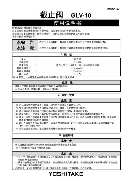
1. 规 格型号GLV-10公称直径8~50A适用流体蒸汽、空气、冷温水、油、其他非危险流体最高使用压力 1.4Mpa※1最高使用温度220℃※1接口方式JIS Rc※1 使用压力与使用温度的关系参照JIS B2051 压力-温度标准。
注 意请确认产品所附的标示内容及所订购型号的规格内容。
※如内容有误,不要使用,请向本公司咨询。
2. 保管、安装注 意(1)产品请保管在室内垃圾、尘埃、湿气较少且通风良好的场所中。
(2)安装请由熟练的专业人员在保护好头部、眼睛、手足的前提下实施。
(3)请在确认流体的流动方向和产品上标示的箭头方向后,正确进行安装。
(4)请实施定心,使连接产品的配管与管轴呈一条直线,不要对产品施加过大的配管应力。
(5)搬运、保管产品过程中会因垫片应力缓和导致紧固压力下降,从而从大螺母部发生泄漏。
请务必在使用前对大螺母实施追加紧固。
(6)阀门开关操作不要施加过大力,请在最大扭矩限制下进行。
限制扭矩如日本阀门工业协会发行的 「阀门用户手册」所示。
(7)可能会发生冻结时,请实施防冻措施和使用后的排水处置。
3.在使用时警 告请在流体流动前确认即使流体流动至配管末端也不会导致危险。
※有可能因流体流出导致物质损害。
注 意(1)全开时,为防止阀门手柄被打开至全开状态导致卡紧而不可回转,即使为全开状态,也请将阀门手柄稍往回旋转45度状态使用。
(2)阀请勿使用过大的力于阀门的开关,请在扭矩的规定范围内操作。
扭矩规定范围请参考日本阀门工业会发行的《阀门客户指导手册》。
阀门的安装说明书(中英文)

阀门的安装说明书(中英文对照)焊接与银钎焊SOLDERING AND SILVER BRAZING务必记住所推荐的阀门的用途是什么,并对所应用的环境进行分析,这样才能决定选用最适合安装什么样的阀门。
在安装正确的阀门之前,为了防止损坏阀门,并保证充分发挥阀门的工作性能,请阅读一下安装指南:Analyze the application to determine which valve is best suited for installations, keeping in mind the service for which the valve is recommended. Before installing the correct valve, review the installation instructions to prevent damage to the valve and to assure its maximum efficiency:先沿着垂直方向切割管道,并修整、去除毛刺,测量管径。
Cut tube end square. Ream, burr and size.使用纱布或钢丝刷清除管道和切割部位,使其金属表面发光发亮。
建议不要使用钢丝绒。
Use sand cloth or steel wire brush to clean both ends to a bright metal finish. Steel wool is not recommended.在管道的外面和焊接罩的内部涂上焊剂,焊剂必须完全覆盖焊接表面。
请有节制地使用焊剂。
Apply flux to outside of tube and inside of solder cup. Surfaces to be joined must be completely covered. Use flux sparingly.要确保阀门处于开启状态。
截止阀使用说明书english

Operational ManualType of product: Globe valveModel Number: 6”-J41H-150LBZHEJIANG MAILON VALVE CO.,LTD浙江迈隆阀门有限公司Date:1.Main Application:1.1 ApplicationSuch valve is mainly used as open and close device on the industrial pipelines for Petroluem, gas and chemicals.1.2 Range of ApplicationTemperature(℃) Medium Nominal pressure(LB)■ -29~425 ■ without corrosive ■ 150□ -29~595 □with corrosive □ 300□ -46~345 □ others □ 400□ -254~800 □ 600□ others □ 900□ 15002.Applicable standard□ ANSI□ API□ MSS□ BS□ ASTM■ others-(ASME B16.34)4.Main characteristics of design:4.1 valve type:□ angle type ■through way type □ Y-type □ others4.2 end connection:■ flange type □ welded type □ threaded type □ others 4.3 bonnet connection:■flanged □pressure retaining □welded □ others4.4 seat:■ parallel type □wedge type □ others4.5 disc:■ normal type □ balance type □ pilot-operated type □ others 4.6 Operation:■hand □electric □ others4.7 The globe has backseat sealing construction,but should replace packing without pressure.5.Main dimensionn and end connection:7.Installation and usage7.1 installation7.1.1 The installation postion of the valve shall be covenient for operation and maintenance.7.1.2 Before the installation of the valve,the following items must be checked whether they are in accordance with the usage condition:valve model number,performance specification,technical requirement,nameplate and marking,installation direction,etc. Especially the installtion direction must be correct.7.1.3 Before the installation,the dirt and rust in the cavity and on the sealing face shall be removed. 7.1.4 To check whether the bolt of the cover flange and the packing gland are tightened.To check the smoothness of the open and close operation.For valves with actuators,to check the travel position,to ensure the sealing but without overload.7.2Usage7.2.1The valve is for open and close,not suitable for adjusting function.It is not permitted to use it over the temperature and pressure limitation.For high temperature application,the bolts should tightened periodically to prevent it from leaking.Less heat grad is necessary.For low temperature application,the impact overload stress concentration is not permitted.7.2.2 For hand operated valve,the clockwise is close direction,and the anti-clockwise is open direction.For the other operation types,the control device indication for open/close shall be consistent with the open/close direction of the valve.8.Maintenance and storage8.1 Maintenance8.1.1 The valve in operation should be checked and maintained periodically to prevent it from rust and jamming.8.1.2 If leakage pls check whether the middle flange and packing gland is loosed,although there are backseat sealing but should not replace packing with pressure;8.1.3If the internal leakage at the sealing faces is found,pls check whether the valve is fully closed position.8.1.4When due time for maintenance of valve,all parts should be cleaned again to remove the dirt and rust.And also to replace the damaged gasket and sealing rings,to lap and adjust the sealingfaces.After maintenance,pls make new pressure test.If the valve is fixed with safety device,the setpressure of the safety device should be re-set as less than 1.1times of the pressure-temperaturevalue.8.2 Storage8.2.1 The valve should be stored in dired house.Stacked or stored in open air is forbidden.8.2.2 The stored valve should have end covers for protection.The naked position of the stem should be protected by oil paper,preventing from damaing.8.2.3 For long time stored valve,it should be maintained periodically:to clean the dirt and rust,re-coat the anti-rust oil/grease,to check the flexibility of operation with no jamming.。
2007 HE-LO 自动停止阀门用户指南说明书
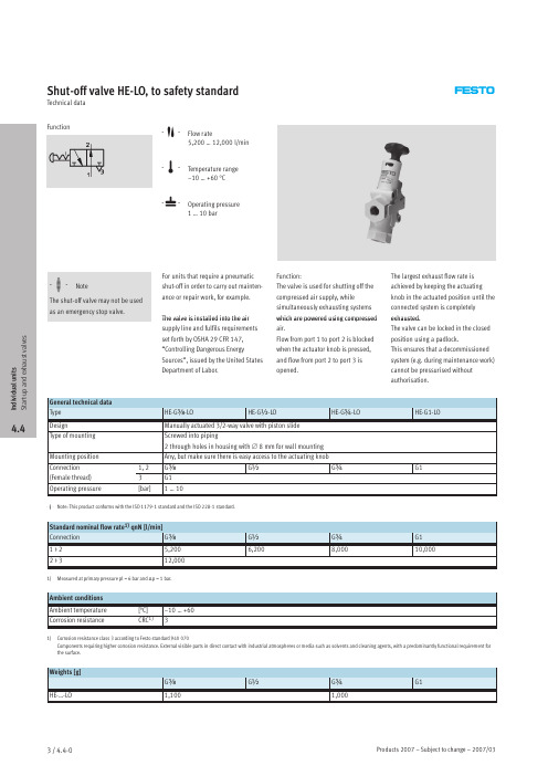
Shut-off valve HE-LO,to safety standardTechnical dataFunction-M-Flow rate5,200…12,000l/min-Q-Temperature range –10…+60°C-L-Operating pressure 1 (10)bar-H-NoteThe shut-off valve may not be used as an emergency stop valve.For units that require a pneumatic shut-off in order to carry out mainten-ance or repair work,for example.The into the air Function:The valve is used for shutting off the compressed air supply,whilesimultaneously exhausting systems are using The largest exhaust flow rate is achieved by keeping the actuating knob in the actuated position until the connected system is completely exhausted.valve is installed supply line and fulfils requirements set forth by OSHA 29CFR 147,“Controlling Dangerous EnergySources”,issued by the United States Department of Labor.which powered compressed air.Flow from port 1to port 2is blocked when the actuator knob is pressed,and flow from port 2to port 3is opened.The valve can be locked in the closed position using a padlock.This ensures that a decommissioned system (e.g.during maintenance work)cannot be pressurised without authorisation.General technical data TypeHE-G y -LO HE-G ½-LO HE-G ¾-LO HE-G1-LODesignManually actuated 3/2-way valve with piston slide Type of mounting Screwed into piping2through holes in housing with ∅8mm for wall mounting Mounting position Any,but make sure there is easy access to the actuating knob Connection 1,2G y G ½G ¾G1(Female thread)3G1Operating pressure[bar]1 (10)-H-Note:This product conforms with the ISO 1179-1standard and the ISO 228-1standard.Standard nominal flow rate 1)qnN [l/min]Connection G y G ½G ¾G11>25,2006,2008,00010,0002>312,0001)Measured at primary pressure pl =6bar and Δp =1bar.Ambient conditions Ambient temperature [°C]–10…+60Corrosion resistanceCRC 1)31)Corrosion resistance class 3according to Festo standard 940070Components requiring higher corrosion resistance.External visible parts in direct contact with industrial atmospheres or media such as solvents and cleaning agents,with a predominantly functional requirement for the surface.Weights [g]G yG ½G ¾G1HE-…-LO1,1001,000I n d i v i d u a l u n i t s S t a r t -u p a n d e x h a u s t v a l v e s4.4Shut-off valve HE-LO,to safety standard Technical dataType D1HE-G y-LO G yHE-G½-LO G½HE-G¾-LO G¾HE-G1-LO G1-H-Note:This product conforms with the ISO1179-1standard and the ISO228-1standard.Ordering dataConnection Part No.TypeG y197133HE-G y-LOG½197134HE-G½-LOG¾197135HE-G¾-LOG1197136HE-G1-LO IndividualunitsStart-upandexhaustvalves 4.4Shut-off valve HE-LO,to safety standardAccessories Padlock LRVS-Dfor shut-off valve Material:Housing:BrassOrdering dataWeight Part No.Type [g]yp Padlock120193786LRVS-DI n d i v i d u a l u n i t sS t a r t -u p a n d e x h a u s t v a l v e s4.4Solenoid valves MFHE/Pneumatic valves VLHEPeripheralsoverview5AccessoriesMFHEVLHE Page 1Solenoid coil MSFG/MSFW –3/4.4-92Plug socket with cable KMF –3/4.4-93Illuminating seal MF-LD –3/4.4-94Plug socket MSSD-F –3/4.4-95Silencer U3/4.4-9I n d i v i d u a l u n i t s S t a r t -u p a n d e x h a u s t v a l v e s4.4Solenoid valves MFHETechnical dataFunction-M-Flow rate1,200…2,900l/min-Q-Temperature range –10…+60°C-L-Operating pressure2…10bar/28…145psi-W-/en/Spare_parts_serviceSolenoid actuated soft start valve for gradual pressure build-up inpneumatic systems.This ensures safe start-up of pneumatic systems.A minimal amount of air flows into the system via an adjustable flow control valve.Output pressure is built up slowly.Downstream cylinders and slowly output pressure reaches approx.50%of the supply pressure,the valve switches to full flow.•For F solenoid coils –12,24,42V DC–24,42,48,110,230,240V AC (50…60Hz)•On-off valve in combination with service -H-NoteManual override can be detented and secured in the initial position.In the depressed position,the man-ual override is advanced automati-cally to its initial position when the valve is actuated.-H-NoteControl voltage should not be switched to downstream solenoid valves until after pressure has been built up.working devices are advanced to their initial positions.When the units•Manual override,detentingGeneral technical data TypeMFHE-3-¼-BMFHE-3-y MFHE-3-½Pneumatic connection 1,2G ¼G y G ½Pneumatic connection 3G ¼G y G ½Nominal diameter [mm]8912DesignDisk seatType of mounting Via through-holes Mounting position AnyValve function 3/2-way valve,single solenoid,closed Exhaust function Without flow control Reset method Mechanical spring Actuation type DirectDirection of flow Non-reversible Sealing principle Soft Response time on/off[ms]12/8020/9428/76Standard nominal flow rate qnN [l/min]Pneumatic connection G ¼G y G ½In flow direction unthrottled 1,2002,1002,9001>2throttledmax.150max.450max.450In venting direction 2>31,6002,7003,400I n d i v i d u a l u n i t s S t a r t -u p a n d e x h a u s t v a l v e s4.4Solenoid valves MFHETechnical dataOperating and environmental conditions Operating pressure [bar]2...10p g p [psi]28 (145)Operating medium Compressed air,lubricated or unlubricated Ambient temperature [°C]–5…+40Temperature of medium [°C]–10…+60Weights [g]Pneumatic connection G ¼G y G ½Solenoid valve MFHE 5508001,000I n d i v i d u a l u n i t s S t a r t -u p a n d e x h a u s t v a l v e s4.4Solenoid valves MFHETechnical dataType B1B2B3B4B5B6D1∅D2∅E1H1MFHE-3-¼-B 277136.5516.485.0522 5.510G ¼82MFHE-3-y 29.7864315.791.528.2 5.510G y 95MFHE-3-½29.790.745.320.393.830.5 6.511G ½98.2Type H2H3H4H5L1L2L3L4L5L6MFHE-3-¼-B 104013211655.664.31014.347.216.5MFHE-3-y 104714512963.470.11014.356.618.7MFHE-3-½10.146.714813271.6761014.763.722.9Ordering dataPneumatic connection Part No.Type G ¼14329MFHE-3-¼-B G y 12908MFHE-3-y G ½10421MFHE-3-½I n d i v i d u a l u n i t s S t a r t -u p a n d e x h a u s t v a l v e s4.4Pneumatic valves VLHETechnical dataFunction-M-Flow rate1,200…2,900l/min-Q-Temperature range –10…+60°C-L-Operating pressure2…12bar/28…180psi-W-/en/Spare_parts_servicePneumatically actuated soft start valve for gradual pressure build-up inpneumatic systems.This ensures safe start-up of pneumatic systems.A minimal amount of air flows into the system via an adjustable flow control valve.Output pressure is built up slowly.Downstream cylinders andwork devices are slowly advanced to their initial positions.When theoutput pressure reaches approx.50%of the supply pressure,the valve switches to full flow.•On-off valve in combination with service units•Manual override,detenting-H-NoteManual override can be detented and secured in the initial position.In the depressed position,the man-ual override is advanced automati-cally to its initial position when the valve is actuated.General technical data TypeVLHE-3-¼-BVLHE-3-y VLHE-3-½Pneumatic connection 1,2G ¼G y G ½Pneumatic connection 3G ¼G y G ½Pneumatic connection 12(pilot air)G x G x G x Nominal diameter [mm]8912DesignDisk seatType of mounting Via through-holes Mounting position AnyValve function 3/2-way valve,single solenoid,closed Exhaust function With flow control Sealing principle Soft Response time on/off [ms]8/238.5/19.525/39Standard nominal flow rate qnN [l/min]Pneumatic connection G ¼G y G ½In flow direction unthrottled 1,2002,1002,9001>2throttledmax.150max.450max.450In venting direction 2>31,6002,7003,400Operating and environmental conditions Operating pressure [bar]2...12p g p [psi]28 (180)Operating medium Compressed air,lubricated or unlubricated Ambient temperature [°C]–10…+60Temperature of medium [°C]–10…+60Weights [g]Pneumatic connection G ¼G y G ½Pneumatic valve VLHE430790980I n d i v i d u a l u n i t s S t a r t -u p a n d e x h a u s t v a l v e s4.4Pneumatic valves VLHETechnical dataType B1B2B3B4B5B6D1∅D2∅E1VLHE-3-¼-B 277136.516.54022 5.510G ¼VLHE-3-y 29.7864315.748.228 5.510G y VLHE-3-½29.790.745.320.25130.5 6.511G ½Type H1H2H3L1L2L3L4L5L6VLHE-3-¼-B 82104055.664.31014.347.216.5VLHE-3-y 95104763.470.11014.356.618.7VLHE-3-½98.210.146.771.6761014.763.722.9Ordering dataPneumatic connection Part No.Type G ¼14330VLHE-3-¼-B G y 12909VLHE-3-y G ½10420VLHE-3-½I n d i v i d u a l u n i t s S t a r t -u p a n d e x h a u s t v a l v e s4.4Solenoid valves MFHE/Pneumatic valves VLHE AccessoriesIndividualunitsStart-upandexhaustvalves 4.4。
截止阀用途和使用说明
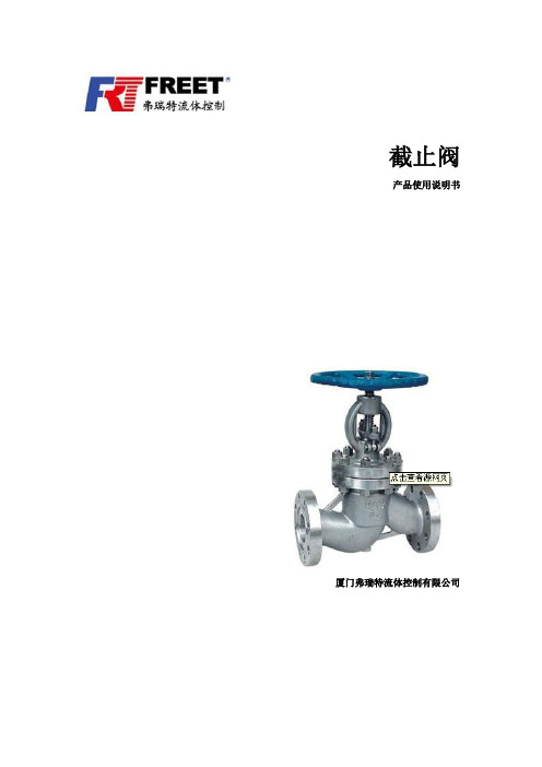
截止阀产品使用说明书厦门弗瑞特流体控制有限公司目录一,截止阀(stop valve,Globe V alve)的启闭件是塞形的阀瓣,密封面呈平面或锥面,阀瓣沿流体的中心线作直线运动。
阀杆的运动形式,有升降杆式(阀杆升降,手轮不升降),也有升降旋转杆式(手轮与阀杆一起旋转升降,螺母设在阀体上)。
截止阀只适用于全开和全关,不允许作调节和节流。
截止阀属于强制密封式阀门,所以在阀门关闭时,必须向阀瓣施加压力,以强制密封面不泄漏。
当介质由阀瓣下方进入阀六时,操作力所需要克服的阻力,是阀杆和填料的磨擦力与由介质的压力所产生的推力,关阀门的力比开阀门的力大,所以阀杆的直径要大,否则会发生阀杆顶弯的故障。
近年来,从自密封的阀门出现后,截止阀的介质流向就改由阀瓣上方进入阀腔,这时在介质压力作用下,关阀门的力小,而开阀门的力大,阀杆的直径可以相应地减少。
同时,在介质作用下,这种形式的阀门也较严密。
我国阀门“三化给”曾规定,截止阀的流向,一律采用自上而下。
截止阀开启时,阀瓣的开启高度,为公称直径的25%~30%时,流量已达到最大,表示阀门已达全开位置。
所以截止阀的全开位置,应由阀瓣的行程来决定。
截止阀的分类1.根据截止阀的通道方向,分为:1)直通式截止阀2)直流式截止阀:在直流式或Y形截止阀中,阀体的流道与主流道成一斜线,这样流动状态的破坏程度比常规截止阀要小,因而通过阀门的压力损失也相应的小了。
3)角式截止阀:在角式截止阀中,流体只需改变一次方向,以致于通过此阀门的压力降比常规结构的截止阀小。
4)柱塞式截止阀:这种形式的截止阀是常规截止阀的变型。
在该阀门中,阀瓣和阀座通常是基于柱塞原理设计的。
阀瓣磨光成柱塞与阀杆相连接,密封是由套在柱塞上的两个弹性密封圈实现的。
两个弹性密封圈用一个套环隔开,并通过由阀盖螺母施加在阀盖上的载荷把柱塞周围的密封圈压牢。
弹性密封圈能够更换,可以采用各种各样的材料制成,该阀门主要用于“开”或者“关”,但是备有特制形式的柱塞或特殊的套环,也可以用于调节流量。
- 1、下载文档前请自行甄别文档内容的完整性,平台不提供额外的编辑、内容补充、找答案等附加服务。
- 2、"仅部分预览"的文档,不可在线预览部分如存在完整性等问题,可反馈申请退款(可完整预览的文档不适用该条件!)。
- 3、如文档侵犯您的权益,请联系客服反馈,我们会尽快为您处理(人工客服工作时间:9:00-18:30)。
Chrome SS
Overlay welding Ferrous alloy
Flexible graphite
5.Maintenance, installation and usage:
5.1The valves shall be kept in a dry and well-ventilated room, the both ends shall be covered. If itisrestored for a long period, it shall be regularly inspected to prevent from rust.
2)If the packing gland is not correctly assembled to stick the stem, the gland nuts willbe evenly loosened to restore a correct place.
3)If the thread of the stem or stem nuts is hurt, it will be removed off after having been disassembled.
5.6A Valve shall be kept in fully open or fully close position after it is installed. It shall not be used as a throttle valve to avoid wearing out its seating surfaces quickly because oferosion.
批注本地保存成功开通会员云端永久保存去开通
Globe valve
O&M MANUAL
J41H-150LB DN15~150
Edited by
Date
Verified by
Date
Approved by
Date
DIRECTORY
1、Applications and Performance specification
6.3 Leakage occurs between bonnet flanges.
1) If the flange nuts are tightened loosely or unevenly, they will be evenly re-tightened.
2)If the faces of the flange are damaged or collected with dirt, they will be repaired orcleaned up.
6.2 Leakage occurs between the seating surfaces between the gate and seat.
1) If there is dirt between them, they will be cleaned by flush washing.
2)If the seating surfaces are damaged, they will be re-lapped, or machined and lappedafter weld deposition, and their surface roughness must be0.4μmand higher.
3.Main overall connection dimensions:
3.1Overall drawing
3.2Flange ends dimensions:
Model
NPS
DN
L
D
D1
D2
b
Z-d
H
W
kg
J41H-150LB
1/2
15
108
88.9
60.5
34.9
9.7
ห้องสมุดไป่ตู้4-16
169
125
3.8
5.4Its inspection packing whether compress tightly and ensure tightness of packing,meanwhileit don’t prevent stem rotated.
5.5A valve can be installed on pipes in any direction, but it should be easy to be checked and operated.。
2、Principle and structural description
3、Main overall dimensions and connecting dimensions
4、Material of main parts
5、Maintenance, installation and usage
3/4
20
117
98.5
70
43
11.2
4-16
180
125
4.2
1 1/2
40
165
127
98.5
73.2
12.7
4-16
347
180
13
2
50
203
152
120.7
92
15.9
4-19
356
180
21
5
125
356
254
216
186
23.9
8-22
463
350
86
6
150
406
279
241.5
216
6、Possible trouble and solution
7.Matters need attentions
1.Applications and Performance specification
1.1 Applications:
Globevalve usedfortheworktemperature ≤ 200℃water, steam, petroleum, petroleum productsmedium inpipeline, whichused toget throughorcut-offthe mediain pipeline.
3)If the gasket on flange is damaged, it will be replaced with a new one.
6.4 The stem cannot operate smoothly.
1) If the packing is over-tightened, please loosen the gland nuts properly and evenly.
25.5
8-22
541
355
113
4.Manly material:
Body、bonnet、disc
Stem
Sealing
Packing
Bolt
Nut
A105
Chrome SS
Overlay welding Ferrous alloy
Flexible graphite
ASTM
A193 B7
ASTM A194 2H
1.2Performance specifications:
Nominal dimension(NPS)
1/2”~6″
in
Pressure(Class)
150
Lb
Test pressure
Shell
3.1
MPa
Seal
2.2
Air
0.6
Application T
-29~425
ºC
Suitable medium
2.2The stembottom anddisc joint together,the top and the stem nut rotationjoint, the clockwisedirectly start rotatehand wheel, when stemdropping,jointing closely disc and seatsealing surface to prevent medium in pipeline.thediscshallrisingwhile hand wheelstartanti-clockwise to rotate thatwillconnectto the mediainpipeline,which meansopen.
2.3The Seat and disc sealing surface used in Stainless steel with overlay welding.
2.4Valve design and manufacture byAPI 6Dstandard;Face-to-face byANSI B16.10standard;Flange ends byANSI B16.5standard;Inspection and test by API 598standard;valve pressure-temperature level byASME B16.34 standard.
5.7Its moving parts shall be kept clean and regularly lubricated.
5.8The valve shallbe checked regularly after used, check the sealing surface,stem, gasket and packing haveworn outor not, If the damage to failure,itsshould be repaired or replacedpromptly.