ICS-300使用说明书修订20141111准
ATN-300型全自动定氮仪-操作手册
ATN-300型全自动定氮仪(蛋白质测定仪)操作说明手册一、概述蛋白质的测定方法,目前仍以1883年凯达尔氏(Kiedahl)发明的定氮法为基础,它根据各种蛋白质都具有固定比数的氮这一事实,通过对氮的测定而推算出蛋白质含量,此法所得的含氮量除了确定属于蛋白质组成成分的氮以外,还包括非蛋白质组成的其他有机及无机态氮,所以换算所得的蛋白质含量称作为粗蛋白含量,一般蛋白质中的含量为18%,换算后即每6.25克蛋白质中含有1克氮,因此6.25成为换算系数K ,但是不同的农产品及其制品的实际含氮量有区别,所以不同农产品必须采用不同的换算系数,如花生、大豆、蚕豆、大麦、小麦、燕麦、黑麦等含氮为17.6%,求得K=5.7,荞麦、葵花籽、亚麻籽、大麻籽、棉花籽、蓖麻籽等换算系数则为K=5.50,玉米、菜籽为6.00,水稻为5.95,上述以外的其他农产品的换算系数均适用6.25。
尽管如此,目前世界上还没有直接分离测定含蛋白质的可行方法。
因此,迄今为止在国内外凯氏定氮法仍然是测定蛋白质含量的经典方法。
所得结果准确、稳定。
我公司研制生产的ATN-300型全自动定氮仪(蛋白质测定仪),是引进消化吸收国内外检测新技术,结合我国国情,应用凯氏定氮法原理,采用化学与物理学相结合完成的成套蛋白质含量快速测定装置。
为粮食、食品、饲料、农业、商检等检测部门提供了理想的检测设备。
二、工作原理ATN-300型全自动定氮仪检测原理为:整套装置,由电加热消化器、全自动蒸馏器两部分组成。
要提高蛋白质含量测定的检测速度,其关键是要加速样品消化煮解的时间,ATN-300型全自动定氮仪消化装置采用井式电加热炉,增大了消化管受热面,使消化管连同管内所注入的10ml H 2SO 4及试样置入消化管插入井式炉内加热取得更佳的热效应,在消化前置入硒片作为催化剂进一步加速消化煮解,大大缩短消化时间。
消化管内溢出的SO 2等有害气体,通过消化管上的排污管经抽吸泵由水带入下水道,有效的抑制有害气体的外逸,由省略了实验室中安装毒气通风橱,试样经40分钟左右消化煮解,即可完全消化。
Milltronics Pointek CLS 300 电容胶带重量传感器说明书

A t Milltronics,we endeavourto design equipment that is simple to use and reliable in its operation,with the aim of satisfying our customers'needs.Milltronics has been designing and manufacturing electronics based process measurement equipment since1954.Our fields of expertise include continuous and point level measurement,weighing and feeding systems and motion sensing.Technologies include ultrasonic,capacitance and microwave radar.Milltronics sells and markets world wide through subsidiaries,distributors and representatives.Through continuous improvement,we are striving to provide our customers with first rate sales information,engineering assistance and after sales support.For more details on our products and services,please contact us and we will provide you with a listing of the offices or representatives nearest you.Table of ContentsAbout Pointek CLS 300 (5)Pointek CLS 300 Outputs (5)Pointek CLS 300 Features (5)Pointek CLS 300 Applications (5)Specifications (7)Installation (11)Location (11)Configuration and Dimensions (13)Standard Version (14)High Temperature Version (15)Ceramic Active Shield Insulator (16)Thermal Isolator (16)Rod Version (16)Changing the Probe’s Length (17)Cable (19)Cable Tensile Strength (20)Cable Weights (20)Shortening the Cable (20)Mounting (21)Multiple units (21)Wall Restriction (21)Process Concerns (22)Interconnection (23)Trip Amplifier (23)Relay Output Connection (24)Solid State Switch (24)Diode Protection (24)Ancillary 2-Wire Output Connection (25)Power Connection (3 or 4 wire connection) (25)Operation (27)Set Up (27)Start Up (28)Alarm Output (29)Troubleshooting (31)Maintenance (32)Appendix I: Application Notes (33)Application Notes (33)About Pointek CLS 300Note:Pointek CLS 300 is to be used only in the manner outlined in thisinstruction manual.The Pointek CLS 300 capacitance level switch provides output on high or low process material levels. When the measured material is at the desired level, the change in capacitance is sensed and a level alarm is triggered.This could be either a “high level alarm” (material rising to reach the desired level) or a “low level alarm” (material falling to reach desired level). Pointek CLS 300 OutputsOne form `C' (SPDT) relayOne isolated, non-polarized, solid-state switchPointek CLS 300 FeaturesNPT, BSPT, JIS (other connections on request)Corrosion resistant construction, PFA, Ceramic and 316L stainless steelwetted parts25m (82 ft) maximum insertion lengthRugged shear and abrasion resistant probeFully adjustable process alarm: level, time delayField adjustable insert lengthESD protection to 55 kv continuous dischargeActive shield technologyPointek CLS 300 ApplicationsLiquids, slurries, powders, granules, and solidsChemical and petrochemicalHigh pressure and temperaturePower Industry (fly-ash)SpecificationsProbeProcess Connections:•NPT/BSPT/JIS 1Wetted Parts:•Standard Version:•AISI 316L/PFA/Peek 2•High Temperature Version:•AISI 316L/Ceramics Al203 (99.7%)2Probe Lengths:•Rod Version:•min. 350mm (14”) - max. 1000mm (40”)•Rope/Cable Version:•min. 500mm (20”) - max. 25000mm (985”) Max. Tensile Force:•1900kg (4188lbs)Pressure Range3:•-1 to +35 barg (-14.6 to +511 psig)Temperature Range3:•Standard Version:•-40 to 200 °C (-40 to 392 °F)•High Temperature Version:•-40 to 400 °C (-40 to 752 °F)•Min. Dielectric Constant (>r):• 1.5Enclosure:•AluminiumEpoxy Coated:•yesNEMA/CSA/IP-Rating:•4/Type4/IP65Cable Inlet:•2 X ½"NPTCertifications:•CENELEC/FM/CSAPower Supply and TransmitterSupply Voltage:•12 - 250 Vac/dc any polarity galvanically isolatedPower consumption:•2VA/2WattWiring connections:•max. 2.5 mm2Temperature ranges:•Operation (Storage):•-40 to 85 °C (-40 to 185 °F)Signal indicators:•3, indicating adjustment control, output status and powerAdjustment Potentiometers:•2, one for time delay adjustment, one for sensitivity adjustmentAdjustment Switches:•5PST dip switch, for time delay select, fail safe selection, time delaytest/adjust, high/low sensitivity.Min. Sensitivity:•1% change in actual capacitanceMax. Temperature Drift:•0.2% of Actual Capacitance ValueMeasurement Frequency:•600 (kHz) maxESD protection•protected to 55kV continuous discharge.Output FunctionsRelay Contact•Contact:•Form ‘C’ (SPDT)(selectable NC or NO contact)•Max. Contact Load (dc):•5A/30Vdc•Max. Contact Load (ac):•8A/250Vac (cos n=1)•Max. Switching Capacity:•150Watt/2000VA•Min. Contact Load•10mA/5Vdc•Time Delay (on and/or Off)•1 - 60 sec.Solid State switch•Output:•Galvanically isolated•Safety:•Non-polarity sensitive transistor•Max. Load:•2 Watt•Max. Switch Voltage:•250Vac/300Vdc•Max. Load Current:•100 mA•Voltage Drop•Below 1 Volt typical @ 50mA•Time Delay (On and/or Off)•1 - 60 sec.Two (2) Wire Switch•With customer supplied external trip devicesProbe - StandardLength•350mm (14”) to 1000mm (40”)Process Size•NPT, ¾” , 1”,1¼”, 1½”•BSPT, ¾”, 1”, 1½”•JIS, ¾”, 1”, 1½”Insulating Material•Standard Version:•PFA•High Temperature Version:•Ceramic•No insulation on active probeTensile kg loadProbe - CableLength • 500mm (20”) to 25000mm (985”)Process Size • NPT/BSPT: 1¼” minimumInsulating Material• AISI 316L SS • PFA insulation optionalTensile kg load• 1900 kg (4188 lbs)Electrode Dimensions • Cable (insulated):•9mm (0.35”)(uninsulated):•6mm (0.24”)• Weight:•32 x 250mm (1.26 x 9.84”)• Butterfly:•175 x168mm (6.89 x 6.61”)Approvals• CE, CSA, NRTL/C, FM, CENELEC • refer to device nameplateInstallationLocationNotes:•Installation shall only be performed by qualified personnel and in accordance with local governing regulations.•This product is susceptible to electrostatic shock. Follow proper grounding procedures.The Pointek CLS 300 as supplied in the standard probe lengths is normally mounted on the vessel top (high detection alarm) or through the tank wall at the detection level (high or low detection alarm).The cable version is designed for top mounting. The cable suspendsvertically so that it reaches into the process at the desired detection level (high or low detection alarm).Angle HorizontalVerticalConfiguration and DimensionsStandard VersionHigh Temperature VersionCeramic Active Shield InsulatorThe High Temperature version, which includes a ceramic Active Shieldinsulator, is recommended when the process temperature is greater than200E C/ 392 E F and / or when the product to be detected is very abrasive. The high temperature version is rated for applications up to 400 E C / 752 E F. See Temperature and Pressure Recommendations for Application on page 33. Thermal IsolatorIf the ambient temperature of the transmitter is expected to exceed85E C/185E F, then a thermal isolator should be used. An isolator provides a separation distance between a high process temperature inside the vessel, and the electronic housing outside the vessel. This reduces the operatingtemperature of the electronics to a value equal or less than 85E C/185E F. Rod VersionThe rod version of the CLS 300 is available in standard lengths from 350Changing the Probe’s LengthThe probe’s length can be shortened in the field by cutting the electrode.Warning:To prevent damage, do not apply torque directly to the main probe assembly.Option 11.Remove the electrode byreleasing the set screw andturning the threadedelectrode end counterclockwise2.Place the upper part of theelectrode in a vice as shownin the Figure.e a wrench to loosen thelower portion of theelectrode.Option 2The Wrong WayIf the process connection itself is put in the vice, then the probe’s internalparts will rotate along with the wrench, and the unit may fail.Cable Tensile StrengthThe tensile strength of the cable at 1900 kg / 4188 lbs should not beexceeded. It is also important to confirm that the load carrying capability of the silo/tank roof is sufficient to withstand the actual force on the cable for any conditions where the force is likely to be as great as 1900 kg / 4188 lbs.A cable (rope) probe with a PFA jacket reduces the possible product build upon the probe, thus also the tensile force on the cable.Cable WeightsA standard weight with optional attachable butterfly enhancer is available forthe cable version. For lower dielectric constant materials (often in solids) the butterfly weight is recommended, since it increases the change incapacitance when the material comes in contact with the cable end. Thiswould be the case when the silo is quite tall (> 15 m/45 ft) and the dielectric< 4)constant is less than (>rShortening the CableThe cable can be shortened using either:•An angle grinder (preferably with a disc suitable for stainless steel); or •Wire cutters (suitable for piano cable Ø6 – 9 mm).To shorten the cable, proceed as follows:1.If present, remove Butterfly from weight;2.Loosen the three set screws and remove weight by pulling it from the cable;3.Grind/cut the cable to the required length, remove rough edges from thecable;4.Insure that the cable strands are properly seated in the lay of the cable (i.e.no wire strands sticking outside the normal cable profile). It is important to insure that this step is properly done before continuing the assembly.5.Push the weight onto the cable while at the same time rotating it counter-clockwise about the cable, making sure that no cable strands are pushed out of their position in the cable and that the cable is fully inserted;6.Re-fasten the weight by tightening the three set screws;7.Attach the butterfly to the weight again.MountingMultiple unitsSensors must be 500 mm (20”)apart.Mount diagonally if there is notenough vertical space.Process Concernskeep out of path of falling material consider material angle of repose protect probe from falling materialInterconnectionTrip AmplifierLoosen the lid clip and remove the enclosure cover.Identification label (underside of enc losure cover)Notes:• Switch and potentiometer settings are for illustration purposes only.Refer to Set Up on page 27.• Relay contact terminals are for use with equipment having noaccessible live parts and wiring having insulation suitable for at least 250 V ac.• Maximum working voltage between adjacent relay contacts shall be250 V ac8A –5A –Relay Output ConnectionRelay shown in de-energized state, K2contacts rated for 8A at 250 Vac / 5A at30 VdcSolid State SwitchSolid state switch to customer’scontrol or instrumentation deviceSwitch shown in de-energized state, K3contact rated for 250 Vac / 300 Vdc 100mA max 2 VA/2W max., non-polarized.Diode ProtectionWhen driving an external relay with either the solid stated switch and / or relay outputs using dc power, protection diodes must be connected in the correct polarity across the relay coil to prevent possible switch / relaydamage due to the inductive spikes generated by the relay coil.Switch capacity100mA max.2 VA/2W max,250 Vac/300 Vdc.Ancillary 2-Wire Output ConnectionNominal 24 Vdc48 Vdc DC volts 22-2646-50R (S)120234Power Connection (3 or 4 wire connection)12 –V dcRefer to Power ConnectionOperationSet UpNote:Set up can be done in the field with the Pointek CLS 300 mounted into process, or in the shop prior to mounting.Dip Switch 1Set on to change the alarm relay status immediately when the sensor detects a change in frequency. Use this setting when time is critical.Set off to change the alarm relay status with a delay by the amount set on potentiometer #1 (P1). Use this setting when you want to slow the response to account for turbulence or false readings.Dip Switch 2Set on to change the alarm relay status immediately when the sensor detects a change in frequency. Use this setting when time is critical.Set off to change the alarm relay status with a delay by the amount set on potentiometer #1 (P1). Use this setting when you want to slow the response to account for turbulence or false readings.Dip Switch 3Set off to indicate the Low fail safe selection.Set on to indicate the High fail safe selection.Dip Switch 4Set on to test the delay of the alarm relays as set by the potentiometer #1(P1).Set off for normal operation.Dip Switch 5Set on for normal sensitivity on the sensor. Use this setting in situations when you are measuring dry solids or non-conductive liquids.S1 - 1Delay offS1 - 2Fail-safeS1 - 3Delay testS1 – 4SensitivityS1 - 5 Disabled Disabled High Test NormalEnabled Enabled Low Normal low Start UpAfter the CLS is properly mounted and the switch bank set up, apply power to the unit. The green LED (L3) lights to indicate the unit is powered andoperational.IndicatorsThe Pointek CLS uses three LEDs for visual indication of the following:L1 (yellow), sensor status:when P2 is properly set, this LED is on whenthe sensor is in contact with the processmaterial (material capacitance is greaterthan the set point, P2). L1 is off when thesensor is out of contact with the processmaterial (material capacitance is less thanthe set point).L2 (red), output status:this LED is an indication of the relay andsolid switch contact status. Refer toOperation \ Output Status.L3 (green), power:this LED is on when the Pointek CLS isproperly powered.Proceed with the set up of the alarm output.delay ‘on’delay ‘off’fail safedelay testsensitivityAlarm OutputAlarm Output StatusCoveredUn-coveredSetpoint AdjustmentIn order to assist you in properly adjusting the alarm set point for reliable and accurate detection of the process material, we have categorized the materials and applications into two cases. Follow the setup procedure associated with the case which includes your application.Case 1:This is the general case encountered in most applications, characterized by the following:• dry solids• low viscosity liquids • hygroscopic / wet solids•high viscosity and high conductivity liquidsCase 2:Case 1Preamble:•insure that L3 (green) is `on '•turn both potentiometers, P1 and P2, fully ccw (counterclockwise)•set S1 switches 1 to 4 `off ' and S1 switch 5 to `on' (normal sensitivity)1.With sensor uncovered and a minimum 100 mm free space all around, turnP2 cw until L1 (yellow) goes `on '.2.Turn P2 ccw until L1 goes `off '.Case 2Preamble:•insure that L3 (green) is `on '•turn potentiometer P1 fully ccw (counterclockwise), and P2 fully cw (clockwise)•set S1 switches 1 to 5 `off '1.Immerse the sensor in the material that has the lowest dielectric constant.L1 (yellow) should be `on '. If not, S1 switch 5 should be set to `on' (normal sensitivity).2.Adjust P2 ccw until L1 goes `off '.3.Immerse the sensor in the material that has the highest dielectric constant,L1 should come `on '.DelayThe alarm actuation can be delayed for either or both `on alarm' and `off alarm' conditions. The selection is made by setting S1-1 and S1-2, refer to Set Up \ Switch Bank. The amount of delay is adjustable from 1 to 60seconds by setting potentiometer, P1.TroubleshootingNo alarm responseL3 off (green LED)Check power supply L1 (yellow) doesn ’trespond to reducing level on the electrodeCheck sensitivity, S1-5,electrode, connections to sensor input on trip amplifier (and zener barrier continuity if used)Alarm won ’t switch when material level moves down the electrodeL1 (yellow) responds to reducing level on the electrodeCheck that relay and L2(red LED) changes state when S1-3 is toggledL1 (yellow) doesn ’t respond to the sensing electrode approaching or touching.Check sensitivity S1-5,electrode, (and zener barrier continuity, if used)L1 (yellow) responds to increasing level on the electrodeAlarm doesn ’t switch when material level moves up the electrodeL1 (yellow) flashes when approaching the alarm trip-pointCheck that relay and L2(red LED) changes state when S1-3 is toggledMaintenanceThe Pointek CLS 300 requires no regular maintenance or cleaning. Even with significant build-up on the CLS 300 level detector electrode, the level switch will continue to operate. Build-up of material on the active shield area will have little or no effect on the performance of the CLS 300.Appendix I: Application Notes Application NotesTemperature and Pressure Recommendations for ApplicationAppendix II: CE ConformityWRITTEN DECLARATION OFCONFORMITYWe,Siemens Milltronics Process Instruments B.V.Nikkelstraat 10 - 4823 AB BREDA - The Netherlands Declare, solely under own responsibility, that the product Point Level Switch,Pointek CLS 300Mentioned in this declaration, complies with the following standards and/or normative documents:Requirements Remarks Certificate No.EMC Directive 89/336/EEC Commercial, lightIndustrial, and industrial97221-KRQ/EMC 00-4024 EN 55011: 1991Emission – Class BEN 50082-2: 1995 Generic Immunity Standard, from which:•EN 61000-4-2: 1995: Electrostatic Discharge (ESD) Immunity•EN 61000-4-3: 1996: Radiated Electro-Magnetic Field Immunity•ENV 50204: 1995: Digital Radio Telephones Immunity•EN 61000-4-4: 1995: Electrostatic Fast Transient (EFT) Immunity•EN 61000-4-5: 1995: Surge Transient Immunity•EN 61000-4-6: 1996: Conducted Radio-Frequency DisturbancesImmunityATEX Directive 94/9/EC Audit Report No. 2003068II 1/ 2 GD EEx d[ia] IIC T6…T10344T 100 °C IP 66KEMA 00ATEXQ3047KEMA 00ATEX2040XEN 50014: 1992General RequirementsEN 50018: 1994 Flameproof Enclosures “d”The notified body is:N.V. KEMA – Utrechtseweg 310 – 6812 AR Arnhem – The NetherlandsLocation: Breda Named Representative: C.S. van Gils Date: October 1, 2000Position: Managing DirectorNote: For specific safety specifications, please consult the instrument labelIndex2-Wire Connection (25)3 or 4 wire connection (25)About Pointek CLS 300 (5)Adjusting Probe Length (17)Alarm Output (29)Setpoint Adjustment (29)Status (29)Ancillary 2-Wire Output Connection (25)Angle of repose (22)Appendix (33)Appendix II (34)Application Notes (33)Applications (5)Approvals (9)Cable (19)Shortening it (20)Tensile Strength (20)Weights (20)Ceramic Active Shield Insulator (16)Certifications (7)Configuration (13)DECLARATION OF CONFORMITY..34 Dimensions (13)High Temperature Version (15)Standard Version (14)Diode Protection (24)Dip Switches (27)ElectrodeShortening the Probe (17)Enclosure coverremoving (23)Falling Material (22)Features (5)High Temperature Version (15)Dimensions (15)High TemperaturesRecommendations (16)Indicators (28)Installation (11)Location (11)Interconnection (23)Ancillary 2-Wire Output Connection25Diode Protection (24)Power Connection (25)LEDs (28)Location (11)Angle (11)Horizontal (11)Vertical (11)Maintenance (32)Material build up (22)Mounting (21)Multiple Units (21)Process Concerns (22)Wall Restriction (21)Operation (27)Alarm Output (29)Set Up (27)Start Up (28)Output status (28)Outputs (5)Pointek CLS 300 (5)Applications (5)Configuration (13)Dimensions (14)Features (5)Outputs (5)Power (28)Power Connection (25)3 or 4 wire connection (25)Power Supply (7)Protection diodes (24)Relay Output Connection (24)Rod Version (16)Sensor status (28)Set Up (27)Dip Switches (27)Setpoint Adjustment (29)Shield Insulator (16)Shortening Probe (17)Solid State Switch (24)Solid stated switch (24)Specifications (7)Standard Version (14)Dimensions (14)Start Up (28)Thermal Isolator (16)Transmitter (7)CANADAGERMANYSWITZERLANDSingapore,Brazil AUSTRALIABELGIUMFRANCEHONG KONGMEXICOTHE NETHERLANDSTHE UNITED KINGDOMTHE UNITED STATES1954 Technology Dr., P .O. Box 4225,Peterborough, Ontario, Canada K9J 7B1T el.: (705) 745-2431 Fax: (705) 741-0466August van de Wielelei 97, 2100 Deurne, Antwerp, BelgiumT el.: +32(0)3326 45 54 Fax: +32(0)3326 05 25Parc de la Sainte Victoire, Bât. 5, 13590, Meyreuil, FranceT el.: +33 4 42 65 69 00 Fax: +33 4 42 58 63 95T el.: (524) 248-1561 Fax: (524) 248-1565Nikkelstraat 10, NL-4823 AB Breda, The Netherlands Tel.: +31(0)76 542 7 542 Fax: +31(0)76 542 8 542709 Stadium Drive, Arlington, Texas U.S.A. 76011T el.: (817) 277-3543 Fax: (817) 277-3894A joint venture in a sales office in and distributors in56 countries.Visit our web site at:182 Normanby Rd., Box 339, South Melbourne, AustraliaT el.: +61 3-9695-2400 Fax: +61 3-9695-2450Friedrichstrasse 69, D-76703, Kraichtal, Germany T el: +49 721 595 4607 Fax: +49 721 595 49371 Hoi Wan Street, Suite 602, Quarry Bay, Hong Kong T el.: +85 2-2856-3166 Fax: +85 2-2856-2962Century House, Bridgwater Road, Worcester, England WR4 9ZQT el: +44 1905 450500 Fax: +44 1905 450501Printed in CanadaPaseo de Loma Dorada # 114, Loma Dorada, Querétaro, Qro. 76060CP 168, Crêt de Plan 23, CH-1095 LUTRYT el. +41 21 791 58 28 Fax. +41 21 791 58 40。
300半自动生化分析仪中文使用手册

★★★★★Microlab 300半自动生化分析仪中文使用手册目录1. 安全注意事项1.1 简介1-2 1.2 操作者资格1-2 1.3 维修人员资格1-2 1.4 标志的描述1-2仪器上的标志1-2 手册中的标志1-2 1.5 电子部分1-3 1.6 机械部分1-3 1.7 灯泡1-3 1.8 化学部分1-3 1.9 生物污染成分1-4样品1-4 废液1-4 生物污染成分1-4 试剂1-4 1.10 附加事项1-5防火1-5 结果的准确性/精密度1-5 应用1-5 操作和保养1-5 安装要求1-6 仪器闲置时的处理1-6 2. 序言2.1 系统外观2-2 2.2 使用手册2-4 2.3 包装运输2-5 2.4 安装2-52.5 验收2-63. 系统描述3.1 概述3-2 3.2 盖子3-2 3.3 吸液器3-3 3.4 测量单元3-4 3.5 泵单元3-5 3.6 打印单元3-6 3.7 屏幕3-73.8 键盘3-83.8.1 硬键3-83.8.2 软键3-93.8.3 字母键3-93.8.4 键头键3-9 3.9 仪器的后面板3-10 3.10 值的输入和软件设置3-113.11 技术数据3-124. 理论4.1 概述4-2 4.2 吸光度4-2 4.3 动力法原理4-3 4.4 终点法原理4-44.4.1 标准终点法4-44.4.2 带试剂空白终点法4-44.4.3 带试剂空白和样品空白的终点法4-54.4.4 双波长终点法4-5 4.5 两点法原理4-64.6 非线性实验4-65. 运行仪器5.1 开机前准备5-2 5.2 开机5-4 5.3 冲洗比色池5-5 5.4 系统参数编程5-65.4.1 前言5-95.4.2 硬件5-115.4.3 滤光片5-135.4.4 仪器5-145.4.5 保护5-16 5.5 建立质控程序5.5.1 质控编程5-175.5.2 修改或清除质控5-195.6 注册定标液5-226. 测试6.1 实验选择6-2 6.2 测量6-36.2.1 水空白6-36.2.2 试剂空白6-46.2.3 定标液6-5附加信息6-76.2.4 质控6-8附加信息6-96.2.5 样品6-10附加信息6-116.2.6 样品空白6-12仅做样品空白6-12样品空白和试剂空白6-136.2.7 测量结果的标志6-156.2.8 测量类型的变换6-166.2.9 屏幕上的软键6-176.2.10 信息屏幕6-18动力学实验信息6-19 6.3 结束测量6-206.4 评估实验6-217. 质量控制7.1 概述7-27.2 统计7-28.实验和定标液编程8-2 8.1 概述8-2 8.2 用户定义的实验编程8-28.2.1 简介8-58.2.2 设置8-6动力法8-6终点法8-7两点法8-78.2.3 范围8-8 8.3 定标液编程8-98.3.1 定标液8-101点定标8-122点定标8-12多点定标8-13因数定标8-138.3.2 标准液8-148.4 在编程菜单和数据菜单的软键8-169. 使用密码9.1 概述9-29.2 修改密码9-310. 保养10.1 半天保养10-2 10.2 每天保养10-4 10.3 更换打印纸10-5 10.4 更换色带10-6 10.5 更换保险10-7 10.6 更换或调节灯泡10-8 10.7 打印保养表10-13 10.8 出错记录10-1310.9 维修10-1411. 故障11.1 常见故障11-211.1.1 样品和试剂的问题11-3样品11-3试剂、定标液和质控物11-311.1.2 分析仪的问题11-311.2 解决方法11-411.2.1 屏幕提示11-411.2.2 数据标志11-511.2.3 无样品吸入11-611.2.4 吸样量不足11-611.2.5 通讯错误11-711.2.6 没有结果11-711.2.7 结果不稳定11-8跳点11-8重复性差11-8结果太低11-9结果太高11-911.2.8 空白错误11-911.2.9 温度错误提示11-10附录A.1 外接键盘A-2A.1.1 安装外接键盘A-2A.1.2 键盘功能A-3A.2 订货信息A-4索引#开放通道个数5-141点定标8-122点定标8-12A吸光度4-2附加信息(定标液)6-7附加信息(质控)6-9附加信息(样品)6-11调节灯泡10-8修改质控5-19样品号自动增加功能5-14,6-10 自动打印结果5-14B仪器的背面3-10波特率5-11双波长终点法4-5C 定标8-10定标曲线8-14测量类型的改变6-16修改密码9-3修改质控6-9修改密码5-16检查选择框3-11,8-4 仪器的清洁6-20色带10-6质控6-8D 每日常规检查5-2日期5-9日期格式5-9E 编辑框3-11,8-4 终止日保养10-4每天工作结束的方法5-5带试剂空白的终点法4-4带试剂空白和样品空白的终点法4-5环境条件3-12方程4-2出错记录10-13评估实验6-21外接键盘5-11外接打印机5-11F 因数定标8-13滤光片5-13滤光片轮5-13标志6-15,6-18 保险丝10-7H 半日保养10-2I 动力法信息6-19信息屏幕6-18安装2-5内置打印机5-4K 键盘3-8动力法4-3L 实验室名称5-9语言5-9Levey-Jennings 图7-2列表框3-11,8-4 语言版本5-10M 保养列表10-13 测量纽6-17测量实验6-2多点定标8-13N 非线性4-3P 病人名称5-14电源要求3-12打印纸10-5标准编程8-9质控编程5-17系统参数编程5-6用户定义实验编程8-2Q 质量控制7-2R 反应图6-17屏幕上的反应6-19试剂空白6-4清除质控5-19换灯泡10-8结果格式5-14S 样品6-10样品空白测量6-12样品码5-14运输2-5标准终点法4-4质控的统计信息7-2T 实验选择6-2时间5-9气泡体积5-14两点法4-6V 确认定标6-5确认质控(按质控)7-2确认质控(按实验)7-2W 验收2-6 水空白6-31.安全注意事项1.1 简介在开始安装和使用仪器之前,应阅读本安全注意事项以及相关章节。
高冠系统说明书

VVVF
广州市西奥电梯有限公司
102
JTK
轿顶急停
103 (无机房用)
KSK1
卡梯开关
103A KSK2
卡梯开关
103B
AK
轿厢急停
104
SJK
上极限开关
107
JSK
夹绳器开关
106
XSK
限速器开关
105
QK
安全钳开关
108 XJK
下极限开关
109 PSE
对重缓冲器开关
110
PSF
轿厢缓冲器开关
113
慢下
48 轿厢检修 49 轿顶检修
53
慢上
慢下
50 51
慢上
慢下
P1
上平层感应器
MQK
门区
P2
下平层感应器
SHK 低速上强迫换速开关
SHK1 高速上强迫换速开关
SXW 上限位
XHK 低速下强迫换速开关
XHK1 高速下强迫换速开关
XXW 下限位
YX1
YJ 安全回路检测
MX1
MSJ1
MX2
MSJ2
X16
6RD 3A
+
302
C1
300
EL10
轿顶插座
EN10
底坑插座
2RD 6A L2 3RD 6A L3
Q2
Q1
AC1
输入
AC2 电源 AC220V 应 急 照 明
380V
6RD 7RD 6A
KEG
8RD 3A 24V
0V 202
220VAC
12 3 相序
EL10
BK2 601 9RD 3A
AC300说明书
目录1 引言 (4)1.1 编写目的 (4)1.2 注意事项 (4)2 启动 (4)3 初始界面 (4)4 应用程序结构与模块 (6)4.1 用户管理 (9)4.1.1 用户登记 (9)指纹登记 (13)ID(Mifare)卡登记 (13)原声录制 (14)拍照 (15)4.1.2 删除登记记录 (17)4.2 设置 (18)4.2.1基本设置 (18)时间设置 (18)语言设置 (18)语音提示 (18)音量调节 (19)按键音 (19)报警设置 (19)4.2.2 高级设置 (19)4.2.2.1 验证界面设置 (19)是否实时拍照 (19)是否显示照片 (19)实时指纹显示设置 (19)4.2.2.2删除全部记录 (19)4.2.2.3 删除全部登记数据 (20)4.2.2.4 恢复出厂设置 (20)4.2.2.5 固件升级 (20)4.2.2.6 夏令时设置: (20)4.2.2.7 功能键设置 (20)4.2.3 电源管理 (20)定时开机 (21)定时关机 (21)定时休眠 (21)响铃设置 (21)空闲设置 (21)锁闭关机键 (21)定时状态转换 (21)4.2.4 通讯设置 (22)机器编号 (22)RS232 (22)RS485 (22)波特率 (22)以太网 (22)IP地址 (22)子网掩码 (22)网关地址 (22)连接密码 (23)动态IP分配 (23)后台地址 (23)4.2.5 记录设置 (23)管理记录警告(报警) (23)验证记录警告(报警) (23)重复确认时间 (23)4.2.6 自动检测 (23)4.3门禁功能设置 (24)4.3.1 时间段设置 (24)4.3.2 分组功能设置 (25)4.3.3 用户门禁设置 (25)4.3.4 开锁组合设置 (26)开锁组合基本设置 (26)开锁组合设置 (26)4.3.5 锁驱动时长 (28)4.3.6 门磁延时 (28)4.3.7 门磁开关设置 (28)4.3.8 胁迫报警设置 (28)胁迫指纹管理 (28)验密码报警 (28)按键求助 (28)报警延迟 (29)4.3.9 错按报警 (29)4.3.10 反潜功能设置 (29)4.3.11 绑定ID (29)4.4 U盘管理 (29)4.5解除报警 (29)4.6系统信息 (30)4.6.1 用户登记数 (30)4.6.2 指纹登记数 (30)4.6.3 验证记录数 (30)4.6.4 管理记录数 (30)4.6.5 已用内存 (30)4.6.6 剩余容量 (30)4.6.7 设备信息 (30)4.7数据查询 (31)验证记录查询 (31)管理记录查询 (31)用户登记查询 (31)5外接端口连接方式 (31)5.1 外接端口总体描述 (31)5.2 连接说明 (32)5.2.1 RS232连接 (32)5.2.2 RS485连接 (32)5.2.3 出门开关连接 (33)5.2.4 门磁连接 (34)5.2.5 报警连接 (34)5.2.6 电锁连接 (35)5.2.7 电铃连接 (36)5.2.8 指纹读头连接 (37)6组网方式 (37)6.1 分体机组网方式 (38)6.2 一体机组网方式 (38)6.3 指纹读头组网方式 (38)7 终端设备组网调线方式说明 (39)7.1分体机调线连接方式图 (40)7.2一体机调线连接方式图 (41)8 控制器使用说明 (41)8.1 控制器外接端口图说明 (42)8.2 控制器连接说明 (42)8.2.1 出门开关连接 (42)8.2.2 门磁连接 (43)8.2.3 报警器连接 (43)8.2.4 电锁连接 (44)8.2.5 电铃连接 (46)9 基本概念与说明 (47)误判 (47)拒判 (47)权限级别 (47)状态键 (47)消息通知 (47)主从机 (48)夏令时(时区设置) (48)1 引言1.1 编写目的用户使用说明书.1.2 注意事项本考勤机不可阳光直射或强烈阳光下工作。
ASCO300中文操作手册概论
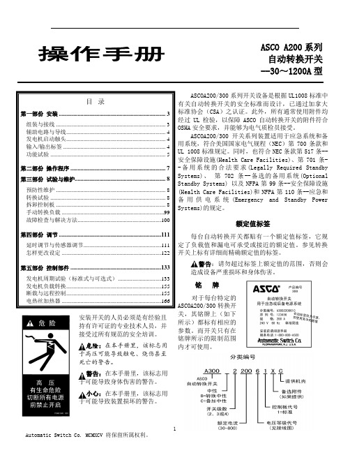
ASCO A200系列自动转换开关--30~1200A型目录第一部份安装 (3)组装与接线 (3)辅助电路与导线 (4)发电机启动触头 (4)输入/输出标签 (4)功能试验 (5)第二部份操作程序 (7)第三部份试验与维护 (8)预防性维护 (8)转换试验 (8)拆卸控制板 (8)手动转换负载 (99)故障检查与解决方法 (100)第四部份调节 (111)延时调节与传感器调节 (111)怎样更改设定 (122)第五部份控制部件 (133)发电机周期试验(标准式与可选式) (133)发电机负载转换 (155)断载与远程控制 (155)电热丝加热器 (166)安装开关的人员必须是有经验且持有许可证的专业技术人员,并接受过所有规范的安全培训。
危险:在本手册里,该标志用于高压可能导致触电、烧伤甚至死亡的警告。
警告:在本手册里,该标志用于可能导致身体伤害的警告。
小心:在本手册里,该标志用于可能导致装置损坏的警告。
ASCOA200/300系列开关设备是根据UL1008标准中有关自动转换开关的安全标准而设计,已通过加拿大标准协会(CSA)之认证。
此外,所有通常使用附件均经过UL检验,以保障ASCO自动转换开关的附件符合OSHA安全要求,并能够为电气质检员接受。
ASCOA200/300开关系列装置适用于应急系统和备用系统,符合美国国家电气规程(NEC)第700条款和UL 1008标准规定。
同时,也符合NEC条款第517条--安全保障设施(Health Care Facilities)、第701条--备用系统的合法要求(Legally Required Standby Systems)、第702条--备选的备用系统(Optional Standby Systems) 以及NFPA第99条--安全保障设施(Health Care Facilities)和NFPA第110条--应急和备用供电系统(Emergency and Standby Power Systems)的规定。
ICS-300使用说明书

前言:承蒙使用ICS-300,不胜感谢!由于皮带秤的运行环境对准确度的影响因素较多,因此,“克服各种环境因素对计量精度的影响,尽可能做到免维护,确保皮带秤长期稳定可靠”是ICS-300的最终目的。
为了充分发挥该系统的良好性能,请在使用前,仔细阅读本说明书。
注意:※不得擅自转载本说明书的部分或全部内容。
※将来对说明书进行修改、补充时不再另行通知。
※本说明书在编写当中,虽然力求完善无误,但是难免有疑点、错误和遗漏之处,当您发现时,敬请告知,谢谢各位的大力合作。
※软件版本号:SSS04300A电话(TEL):,5880910传真(FAX):,5880911 邮编:244000恒速计量秤快速设置指南例如皮带机的参数为:皮带运行一整圈为125秒;皮带机的速度为米/秒;早中晚班起始时间分别为:0:30、08:30、16:30;额定输送量:150吨/设定1 :校零(标定)时间 → 小流量不计值 → 人工带速 → 带速允许误差 → 早班起始时间 → 中班起始时间 → 晚班起始时间 →设定2 :人工综合修整系数 → 人工流量修整点1 → 人工流量修整点2 → 人工流量修整系数1 → 人工流量修整系数2 →滤波系数 → 机号 →← 年 月 日 ← 时 分 秒 ← 选择Y ,更新时间目录一、主要特点 4二、组成及原理 5三、主要性能 5四、使用前的准备工作 6五、注意事项 7六、秤架的安装调试 7七、仪表面板 8八、功能选择 9九、设定 9十、校零 13 十一、标定 14 十二、时钟设置 15 十三、报表查询 15 十四、累计量清零 16十五、仪表外形尺寸 16 十六、后面板(接线图) 17一、主要特点出色的重复性:在正常情况下200个工作日内无需校秤;仪表汉字菜单:现场皮带机维护人员只需简单培训即可操作;安装调试简便:在拆除原托辊组的位置安装几小时就可搞定;维护成本极低:秤架无支点、无杠杆、基本免维护;集称重控制、流量调整、可编程控制、继电器输出于一体,可准确方便的实现各种复杂的控制;两路A/D转换,一路用于称重传感器的测量,另一路用于外部电流或电压信号的测量;多路外部输入信号检测口、模拟量输出、继电器输出口;在控制过程中意外掉电时,控制状态自动保护。
ICS-17JS电子称重仪表说明书
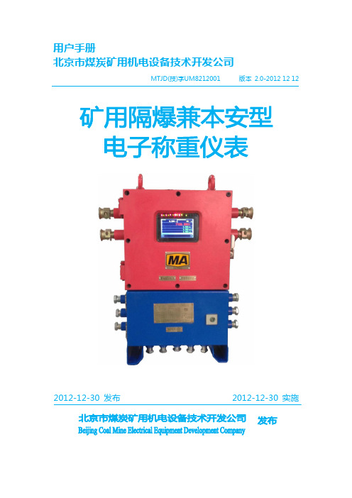
用户手册
文档名称 编写部门 发布日期 制定 审阅
ICS-17JS-矿用隔爆兼本安型称重仪表用户手册 技术部 2012 年 12 月 30 日 田栢林
斯凯尔工业自动化 北京市煤炭矿用机电设备技术开发公司
斯凯尔
斯凯尔工业自动化
MTJD(技)字UM8212001
ICS-17JS-A矿用隔爆兼本安型电子称重仪表
3.4 显示屏 .......................................................................................................................... 25
3.5 环境要求 ..................................................................................................................... 26
4.4.1 操作选择菜单结极 .............................................................................................. 34
4.4.2 操作选择菜单的选择步骤 .................................................................................. 34
4.1 上电自检 ..................................................................................................................... 28
- 1、下载文档前请自行甄别文档内容的完整性,平台不提供额外的编辑、内容补充、找答案等附加服务。
- 2、"仅部分预览"的文档,不可在线预览部分如存在完整性等问题,可反馈申请退款(可完整预览的文档不适用该条件!)。
- 3、如文档侵犯您的权益,请联系客服反馈,我们会尽快为您处理(人工客服工作时间:9:00-18:30)。
设定 1 :
Set 一 1
校零(标定)时间 → ct 0125
小流量不计值 → sma11 000.00
人工带速
→ vset 00.800
带速允许误差
→ △v/v 000
→ ptk2 01.000
→ fn
10
→ jh
01
时钟设定 date 04-06-01 time 09 : 30 : 30 save Y/N
← 年月日 ← 时分秒 ← 选择 Y,更新时间 - 2-
目
录
一、 主要特点
4
二、 组成及原理
5
三、 主要性能
5
四、 使用前的准备工作
6
五、 注意事项
7
六、 秤架的安装调试
7
七、 仪表面板
8
八、 功能选择
9
九、 设定
9
十、 校零
13
十一、 标定
14
十二、 时钟设置
15
十三、 报表查询
15
十四、 累计量清零
16
十五、 仪表外形尺寸
16
十六、 后面板(接线图)
17
- 3-
一、主要特点
z 出色的重复性:在正常情况下 200 个工作日内无需校秤; z 仪表汉字菜单:现场皮带机维护人员只需简单培训即可操作; z 安装调试简便:在拆除原托辊组的位置安装几小时就可搞定; z 维护成本极低:秤架无支点、无杠杆、基本免维护;
电源电压范围为:AC180~240V,最大消耗为 20W. ◆ 使用温度:
本控制器在-10℃~40℃的温度范围内工作,请不要安装 在日光照射的场所。 ◆ 储存温度:
本控制器可在-40℃~80℃的温度范围内保存,但要避免 在高温下长期保存。
六、秤架的安装调试
z 确定安装位置后,在该位置拆下皮带机的 1—3 组托辊,将秤架 用螺栓固定在被拆托辊组位置;
z 秤架的底座在沿皮带宽度方向上应调水平; z 秤架上托辊的轴线应与皮带宽度方向平行; z 秤架在沿皮带宽度方向上应对称安装; z 秤架上托辊的上表面不得低于其前后各一组托辊的上表面,同
时称量段上的托辊组上表面均不得低于皮带机上其它各托辊的 上表面; z 秤架及其前后各三组托辊组的上表面尽量地调整到一个平面,
前 言:
承蒙使用 ICS-300, 不胜感谢!
由于皮带秤的运行环境对准确度的影响因素较多,因此,“克服 各种环境因素对计量精度的影响,尽可能做到免维护,确保皮带秤长 期稳定可靠”是 ICS-300 的最终目的。为了充分发挥该系统的良好 性能,请在使用前,仔细阅读本说明书。
注 意:
※ 不得擅自转载本说明书的部分或全部内容。 ※ 将来对说明书进行修改、补充时不再另行通知。 ※ 本说明书在编写当中,虽然力求完善无误,但是难免有疑点、
- 8-
校零 → 标定 → 设定 1 → 设定 2 → 设定 3 →
八、功能选择
功能选择 cal-z set-4 cal-p time set-1 view set-2 clear set-2 run
← 设定 4 ← 校时 ← 报表查询 ← 清除计量 ← 返回运行
按“ ”键时选择适当的功能。按“ ”键进入所选功能。
设定 3 :
最大流量
→
测速斜率
→
A-B 秤之间距离 →
综合参数
→
备用 2
→
卸载时间
→
加载时间
→
Set 一 3
ptmax ×××.××
vsk ××.×××
ptset ×××.××
zhp ×××
sc
×.××
kp
××.×
ki
××.×
说明: (1)最大流量 ptmax 决定了流量输出(4-20mA)的最大值; (2)当测速速度与显示速度不一致时,修改 vsk,计算公式为:
(01.001),砝码的重量密度增加 1‰,每减少一个数字。砝 码的重量密度减少 1‰; (4)滤波系数越大,流量 4/20mA 以及 PID 4/20mA 输出变化的周期 越长(例如:fn=10,1 秒变化 1 次;fn=50,5 秒变化 1 次。 计量秤一般设定为 5-15,应根据调节效果设定)。滤波系数与 累计量无关; (5)通讯波特率与机号: 波特率 1~5 分别表示波特率为:1200,2400,4800,9600,19200; 机号的范围为:0~31,RS485 的“+”端接至通讯口的“H” 端;RS485 的“-”端接至通讯口的“L”端;
z 在满足上述要求的同时称重传感器的输出应调到一致。
- 7-
七、仪表面板
z 接上电源,自动进入运行状态:
×x×x 月 xx 日 xx 时 xx 分 xx 秒
流量
×××.××
班产量 ×××××.××
累计量 ×××××××.×
z 单位: 流量 t/h ; 带速 m/s ; 重量 t ; 时间 s 。
z 画面切换: 在运行状态下,按“↑”和“↓”键时切换显示画面,按“ ” 键进行功能选择。
台控制器均可方便地与计算机联网; z 针对实物 校验难的问题,我们利用仪表内单片机的资源在不增
加硬件的条件下,建立数学模型开发出一种崭新的实物校验方 法(此法优于链码校验,接近实物校验)解决了实物校验难的 问题,节省了实物校验系统的大量投资(详见工业计量 98 年第 一期); z 多种结构的专利免维护秤架(称量段 1.2 米~4.8 米)适合不 同的工艺要求。
z 集称重控制、流量调整、可编程控制、继电器输出于一体,可 准确方便的实现各种复杂的控制;
z 两路 A/D 转换,一路用于称重传感器的测量,另一路用于外部 电流或电压信号的测量;
z 多路外部输入信号检测口、模拟量输出、继电器输出口;
z 在控制过程中意外掉电时,控制状态自动保护。通电后,控制 器会连续掉电前的状态;
设定 1 :
九、设 定
校零(标定)时间 →
小流量不计值 →
人工带速
→
带速允许误差 →
早班起始时间 →
中班起始时间 →
晚班起始时间 →
Set 一 1 ct ×××× sma11 ×××.×× vset ××.××× △v/v ××× c-1 ××.×× c-2 ××.×× c-3 ××.××
说明: (1)“校零(标定)时间 ct” 是指: 皮带运行整数圈的时间。 (2) “小流量不计值” sma11=0 时,正负流量都累计,sma11>0
错误和遗漏之处,当您发现时,敬请告知,谢谢各位的大力 合作。 ※ 软件版本号:SSS04300A
电话(TEL):0562-5880910 传真(FAX):0562-5880911 邮编:244000
- 1-
恒速计量秤快速设置指南
例如皮带机的参数为: 皮带运行一整圈为 125 秒;皮带机的速度为 0.8 米/秒
z 使用前需确认的基本参数: · 皮带宽度(毫米); · 皮带速度(米/秒); · 皮带运行整圈时间(秒); · 早、中、晚班起始时间(时、分); · 每小时最大输送量(吨/小时); · 仪表与秤架的距离(米); · 与基本计量无关的其它要求的测控参数。
z 确定秤架的安装位置: · 应安装在皮带机的尾部,但下料点距秤体最小距离为 6m, (短皮带机另议); · 在秤架的前后各五组托辊的范围内不得有纠偏装置; · 应避开凹凸部位 12m 以上; · 装秤架的部位要有足够的钢度;
z 电源:
AC180~240V 49Hz~51Hz
z 使用温度:
-10℃~40℃
z 相对湿度:
<90%
z 开孔尺寸:
152mm × 76mm
-5-
四、使用前的准备工作
z 首先根据工艺要求和现场实际工艺条件做出最理想和最保守的 准确度评估;
z 安装条件(±0.25%级秤): (如不能满足下述条件,系统应降级使用,如:0.5%-2%) 皮带机必需是固定型,并符合TD-75 标准,(其它型号或非标
早班起始时间 → c-1 00.30
中班起始时间 → c-2 08.30
晚班起始时间 → c-3 16.30
设定 2 :
人工综合修整系数 备用 备用 砝码重量密度 砝码重量密度系数 滤波系数 波特率与机号
Set 一 2
→ ptk 01.000
→ pt1 075.00
→ pt2 125.00
→ ptkl 01.000
时,低于 sma11 的流量均不累计;该值也可人工修改,(人工修 改 sma11 可根据皮带机的运行状况而定, sma11 太小, 空皮带
-9-
运行时容易造成仪表累计, sma11 太大,小流量运行时容易造 成仪表不累计。 (3)“人工带速 vset”是指皮带机的额定速度; (4)“带速允许误差” △v/v=0,用于恒速秤;△v/v=100,用于调 速秤;△v/v 在 0~100 之间(整数),用于测速自动转入恒速; (例如:△v/v=5,是指:由于测速装置的故障,造成相对皮 带机的额定速度误差只要大于 5%,系统就自动采用恒速); V— 皮带机的额定速度,△V— [皮带机的额定速度-测速速度] (5)不需的班次,起始时间设成 25 时。班次可以跨日。但是早、 中、晚各班的起始时间必须在当日。(例如:每天分 2 班,早 班 7:30~15:30 晚班 16:00~24:00,可设定 C-1=07.30、 C-2=16.00、C-3=25,但 15:30~16:00 的产量算早班、 24:00~7:30 的产量算晚班)
三、主要性能
z 动态累计误差:≤±0.25%,(流量在额定流量的 20%-100%);
z 计量能力不小于 3000t/h;4-20 mA 瞬时量输出; z CAN 工业总线接口、RS485 接口;