CiSCO光模块型号
思科GLC-T、GLC-TE与SFP-GE-T电口模块有何区别?
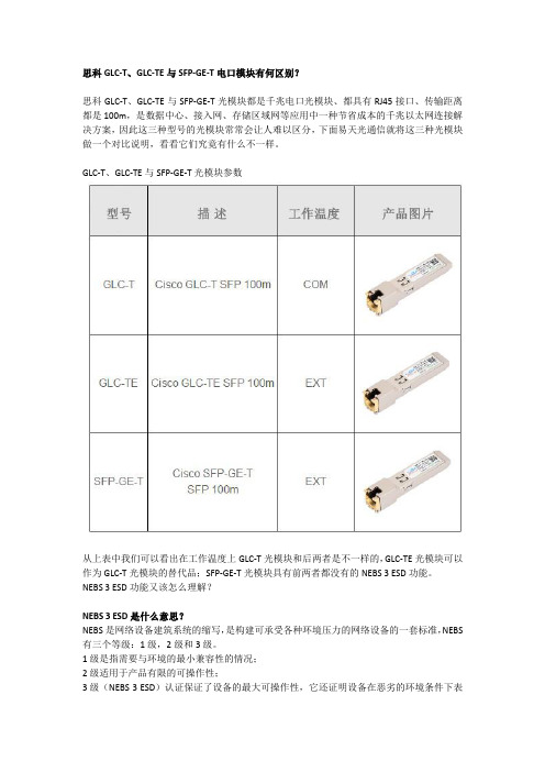
思科GLC-T、GLC-TE与SFP-GE-T电口模块有何区别?思科GLC-T、GLC-TE与SFP-GE-T光模块都是千兆电口光模块、都具有RJ45接口、传输距离都是100m,是数据中心、接入网、存储区域网等应用中一种节省成本的千兆以太网连接解决方案,因此这三种型号的光模块常常会让人难以区分,下面易天光通信就将这三种光模块做一个对比说明,看看它们究竟有什么不一样。
GLC-T、GLC-TE与SFP-GE-T光模块参数从上表中我们可以看出在工作温度上GLC-T光模块和后两者是不一样的,GLC-TE光模块可以作为GLC-T光模块的替代品;SFP-GE-T光模块具有前两者都没有的NEBS 3 ESD功能。
NEBS 3 ESD功能又该怎么理解?NEBS 3 ESD是什么意思?NEBS是网络设备建筑系统的缩写,是构建可承受各种环境压力的网络设备的一套标准,NEBS 有三个等级:1级,2级和3级。
1级是指需要与环境的最小兼容性的情况;2级适用于产品有限的可操作性;3级(NEBS 3 ESD)认证保证了设备的最大可操作性,它还证明设备在恶劣的环境条件下表现良好,不会干扰周围的其他电子设备,NEBS 3级认证的网络设备在关键业务应用中至关重要。
也就是说,与GLC-T或GLC-TE相比,SFP-GE-T光模块它可以承受更大的应力,更不容易发生故障。
如何选择思科SFP-GE-T、GLC-TE和GLC-T光模块?事实上这三种光模块达到的传输效果是相似的,选择何种光模块都能实现千兆传输,不过值得注意的是,原装的思科GLC-T和SFP-GE-T光模块在2017年6月1日已经终止销售,并被GLC-TE光模块取代。
如果直接与电信公司(对NEBS有要求)交易的话,需要选择具有NEBS 3 ESD功能的SFP-GE-T 光模块。
GLC-T和GLC-TE光模块的成本较低,也能满足千兆以太网的需求思科GLC-T、GLC-TE与SFP-GE-T光模块在数据中心、企业网等应用中都有十分广泛的应用,它常用在思科(Cisco)Catalyst 2970/3560/3750等网络设备中,提供10/100/1000Mbps的传输速率。
光纤模块知识
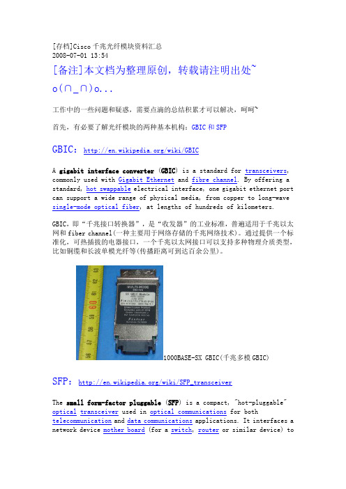
[存档]Cisco千兆光纤模块资料汇总2008-07-01 13:54[备注]本文档为整理原创,转载请注明出处~o(∩_∩)o...工作中的一些问题和疑惑,需要点滴的总结积累才可以解决,呵呵~首先,有必要了解光纤模块的两种基本机构:GBIC和SFPGBIC:/wiki/GBICA gigabit interface converter (GBIC) is a standard for transceivers, commonly used with Gigabit Ethernet and fibre channel. By offering a standard, hot swappable electrical interface, one gigabit ethernet port can support a wide range of physical media, from copper to long-wave single-mode optical fiber, at lengths of hundreds of kilometers.GBIC,即“千兆接口转换器”,是“收发器”的工业标准,普遍适用于千兆以太网和fiber channel(一种主要用于网络存储的千兆网络技术)。
通过提供一个标准化,可热插拔的电器接口,一个千兆以太网接口可以支持多种物理介质类型,比如铜缆和长波单模光纤等(传播距离可到达百余公里)。
1000BASE-SX GBIC(千兆多模GBIC) SFP:/wiki/SFP_transceiverThe small form-factor pluggable (SFP) is a compact, "hot-pluggable" opticaltransceiver used in optical communications for both telecommunication and data communications applications. It interfaces a network device mother board (for a switch, router or similar device) toa fiber optic or unshielded twisted pair networking cable.SFP是一种结构紧凑、支持热插拔且被广泛应用于通信和数据传输应用中的光接收器。
Cisco兼容40G QSFP+ 光模块用户指南说明书
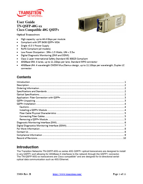
User GuideTN-QSFP-40G-xxCisco Compatible 40G QSFP+Optical Transceivers•High capacity: up to 44.4 Gbps per module•Compliant with SFF 8436 QSFP+ MSA•Single +3.3 V Power Supply•RoHS Compliant (all models)•Low Power Dissipation : SR4< 1.5 Watts, LR4 < 3.5w•Digital Diagnostic Monitoring (DMI and DDMI)•Class 1 Laser International Safety Standard IEC 60825 Compliant•40GBase-SR4: 4 lanes, up to 11.1Gbps per lane, Standard MPO connector•40GBase-LR4: 4 wavelength CWDM Mux/Demux design, up to 11.1Gbps per wavelength, Duplex LC connectorContentsIntroduction (1)Description (2)Ordering Information (2)Specifications and Standards (2)Optical Specifications (2)Application: Fiber Connection with QSFP+ (3)QSFP+ Unpacking (3)QSFP+ Installation (4)Cautions (4)Installing a QSFP+ Module (4)Fiber Cable Physical Characteristics (5)Connecting Fiber Cables (5)Removing a QSFP+ Module (5)Diagnostic Monitoring Interface (DMI) (6)Digital Diagnostics Monitoring Interface (DDMI) (7)For More Information (8)Contact Us (8)Compliance Information (9)Record of Revisions (10)IntroductionThe Transition Networks TN-QSFP-40G-xx series 40G QSFP+ optical transceivers are designed to install in any QSFP+ port allowing for 40GBase-X interfaces to the network through the QSFP+ connector.The TN-QSFP-40G-xx transceivers are Cisco compatible* and are designed for bi-directional serial-optical data communication such as 40G Ethernet.DescriptionTransition Networks’ QSFP+ modules fully comply with the Multi-Sourcing Agreement (MSA).This compliance allows our QSFP+ modules to be used in all other MSA compliant QSFP+ platforms. In addition, TN QSFP+ modules are also compatible with all Cisco QSFP+ based routers and switches, as well as Cisco’s IOS software. TN QSFP+ modules are not Cisco OEM brand modules. Ordering InformationProduct Number DescriptionTN-QSFP-40G-LR4 QSFP+ 40GBase-LR4, 1271nm, 1291nm, 1311nm, 1331nm, single mode (LC)[10km/6.2mi.] Link Budget: 7.0 dBTN-QSFP-40G-SR4 QSFP+ 40GBase-SR4, 850nm multimode (MPO) [400m/1313ft. on OM4, 300m/985ft. on OM3] Link Budget: 2.3 dBTN-QSFP-40G-LR4-3 QSFP+ 40GBase-LR4, 1271nm, 1291nm, 1311nm, 1331nm single mode (LC)[30km/18.7mi.] Link Budget: 9.0 dBSpecifications and StandardsThe TN-QSFP-40G-xx was designed to meet these standards and specifications:Optical SpecificationsThe Optical Specs for all Transition Networks’ SFPs are available on our Optical Devices webpage.Application: Fiber Connection with QSFP+Applications include: 40G Ethernet, 10G Ethernet, and Data Center Aggregation Connection.QSFP+UnpackingBefore you start installing the TN-QSFP-40G-xx, verify that the package contains the following items: o One TN-QSFP-40G-xx SFPo Two protective foam pieceso One Documentation PostcardNotify your sales representative immediately if any of the above items is missing or damaged. Save the packaging for possible future use.The optical ports of the QSFP+ transceiver must be terminated with an optical connector or with a dust plug. The QSFP+ transceiver must be operated within the specified temperature and voltage limits.QSFP+ InstallationCautions•The QSFP+ tranceiver module is keyed to only be installed one way. However, if forced the wrong way, damage may occur. •Avoid getting dust or other contaminants into the fiber bore of the QSFP+ transceiver module. •Clean the optic surfacees of the optical fiber before you plug them back in to the optical bores of another QSFP+ tranceiver module. • Each port must match the wavelength specifications on the other end of the cable, and the cablemust not exceed the specified cable length for reliable communications.Installing a QSFP+ Module1. Attach an ESD-preventive wrist strap to your wrist and to the ESD ground connector or a bare metalsurface on your chassis.2. Remove the QSFP+ transceiver module from its protective packaging. Note: Do not remove theoptical bore dust plugs until directed to do so in a later procedure.3. Check the slot orientation. Note that for some devices (e.g., S4224) some slots are “upside down”compared to other slots.4. Position the QSFP+device at the desired installation slot, with the label facing correctly.5. Carefully slide the QSFP+ device into the slot, aligning it with the internal installation guides.Triangleindicates bottomof SFP cageSFP Module Label side top of SFP moduleBaleClasp SwitchFully Inserted SFPSwitch 6. Ensure that the QSFP+device is firmly seated against the internal mating connector. To verify that theQSFP+ is seated and latched properly. a ) Grasp the QSFP+ by the sides and try to remove it without releasing the latch. b) If the QSFP+ can not be removed, it is installed and seated properly. If the QSFP+ can be removed, reinsert it and press harder with your thumb; repeat if necessary until it is latched securely into the socket.7. Connect the fiber cable to the fiber port connector of the QSFP+ device. Make sure the QSFP+release latch is in the up (closed) position when you insert the cable connector into the QSFP+.8. Remove the dust plug from the connector. Save the dust plug for future use.9. Attach an appropriate cable into the QSFP+ module port.10. Attach the other end of the cable into the other device.11. Observe the status LED(s). See the related manual for details.Fiber Cable Physical CharacteristicsThe fiber cable physical characteristics must meet or exceed IEEE 802.3ae specifications:•Single mode fiber (recommended): 9 μm•Multimode fiber (recommended): 62.5/125 μm•Multimode fiber (optional): 100/140, 85/140, 50/125 μmWarning: Visible and invisible laser radiation when open. DO NOT stare into laser beam or view directly with optical instruments. Failure to observe this warning could result in damage to your eyes or blindness. Connecting Fiber CablesTo install the fiber cable, do the following:1. Locate the appropriate fiber cable.2. Install the cable as shown below.Removing a QSFP+ModuleCaution: Be careful when removing the QSFP+ from a device. Some QSFP+ transceiver module temperatures may exceed 160°F (70°C) and be too hot to touch with bare hands. Note: Do not remove and replace the QSFP+ modules more often than necessary; excessive QSFP+ removing and replacing can shorten the useful life of the QSFP+.1. Attach an ESD-preventive wrist strap to your wrist and to the ESD ground connector or a bare metalsurface on your chassis.2. For future reattachment of fiber-optic cables, note which connector plug is send (TX) and which isreceive (RX).3. Remove the QSFP+ transceiver module:a. If the QSFP+ transceiver module has an actuator button latch, gently press the actuator buttonon the front of the QSFP+ transceiver module until it clicks and the latch mechanism releases the QSFP+ transceiver module from the socket connector. Grasp the actuator button between your thumb and index finger, and carefully pull the QSFP+ transceiver module straight out of the module slot.b. If the QSFP+ transceiver module has a bail clasp latch, pull the latch out and down to eject theQSFP+ transceiver module from the socket connector. If the bail clasp latch is obstructed and you cannot use your index finger to open it, use a small, flat-blade screwdriver or other long, narrow instrument to open the bail clasp latch. Grasp the QSFP+ transceiver module between your thumb and index finger, and carefully remove it from the socket.4. Replace the Dust Plug.5. Place the removed QSFP+ transceiver module in an antistatic bag or other protective package.Diagnostic Monitoring Interface (DMI)The following DMI port screen and explanation table contains brief definitions of the DMI support offered on some QSFP+ transceiver modules. For further information, see the help option on the CPSMM-xxx, SNMP agent, or Transition Networks Focal Point or ION System GUI. Note: This feature is not availableon all devices and may vary between products. See the related manual for more information.DMI Parameter Description DMI Rx PowerMeasured receive optical power in microwatts and in decibels relative to 1mW. DMI Rx PowerAlarmAlarm status of measured receive optical power. DMI Temp Internally measured temperature of transceiver in degrees Celsius and degreesFarenheit.DMI Temp Alarm Alarm status for internally measured temperature of the transceiver.DMI Bias Current Measured transmit bias current in microamperes.DMI Bias Alarm Alarm status for measured transmit bias current for the interface.DMI Tx Power Measured transmit power in microwatts and in decibels relative to 1mW. DMI Tx Power Alarm Alarm status of measured transmit power.Rx Power Intrusion Threshold Tells the converter to stop passing traffic when the receive power drops belowthe new threshold. This feature is sometimes referred to as 'Intrusion Detection,' since tapping into a fiber to intercept traffic leads to a reduction in receive power.This value can be entered in microwatts or in decibels relative to 1mW.TN-QSFP+ distances, TX power, RX power, and link budgets can be found on Transition Netwoks’ website, document “SFP/XFP Fiber and Copper Connectors.” See at https:///. The fiber optic transmitters on this device meet Class I Laser safety requirements per IEC-825/CDRH standards and comply with 21 CFR1040.10 and 21CFR1040.11.WARNING: Visible and invisible laser radiation when open. Do not stare into the beam or view the beam directly with optical instruments. Failure to observe this warning could result in an eye injury or blindness. IMPORTANT: Copper based media ports such as Twisted Pair (TP) Ethernet, USB, RS232, RS422, RS485, DS1, DS3, Video Coax, etc., are intended to be connected to intra-building (inside plant) linksegments that are not subject to lightening transients or power faults. Copper-based media ports such as Twisted Pair (TP) Ethernet, USB, RS232, RS422, RS485, DS1, DS3, Video Coax, etc., are NOT to be connected to inter-building (outside plant) link segments that are subject to lightening transients or power faults.Digital Diagnostics Monitoring Interface (DDMI)DDMI (Digital Diagnostics Monitoring Interface) provides enhanced digital DMI for optical transceivers which allows real time access to device operating parameters.This section contains brief definitions of the DDMI support offered on some QSFP+ transceiver modules. For further information, see the help option or User Guide for the S3290, S4140, S4212, and S4224. Note: This feature is not available on all devices and may vary between products.The Transceiver Information and DDMI Information sections are described below. DDMI ParameterDescription DMIRx Power (uW) Intrusion Threshold; a level for Rx Power on the Fiber port. If the DMI read value falls below the preset value, an intrusion is detected, and a trap is generated. The default is 0 uW. The range is 0 - 65,535 uW. PortThe device’s port number. VendorThe QSFP+ vendor’s name (e.g., Transition ). Part NumberThe QSFP+ vendor Part number provided by the QSFP+ vendor (TN-10GSFP-SR ). Serial NumberThe QSFP+ Vendor Serial number provided by the QSFP+ vendor (e.g., 8672105). RevisionThe QSFP+ vendor Revision level for part number provided by the QSFP+ vendor. Data CodeThe vendor's manufacturing date code (e.g ., 2011-08-09). TranseiverThe Transceiver compatibility (e.g., 1000BASE_SX or 10G ). CurrentThe current value of temperature, voltage, TX bias, TX power, and RX power. High Alarm ThresholdThe high alarm threshold value of temperature, voltage, TX bias, TX power, and RX power. High Warn ThresholdThe high warn threshold value of temperature, voltage, TX bias, TX power, and RX power. Low Warn ThresholdThe low warn threshold value of temperature, voltage, TX bias, TX power, and RX power. Low Alarm Threshold The low alarm threshold value of temperature, voltage, TX bias, TX power,and RX power.For More InformationTechnical information in this document is subject to change without notice. For more information see the TN SFP webpage.40 Gigabit Ethernet ("40GbE" or "40G") Port Types (40GBASE-CR4, 40GBASE-KR4, 40GBASE-SR4, 40GBASE-LR4, 40GBASE-ER4, 40GBASE-FR, 40GBASE-T) ITU standards descriptions include:40GBASE-SR4 ("short range") is a port type for multi-mode fiber and uses 850 nm lasers. Its Physical Coding Sublayer 64b/66b PCS is defined in IEEE 802.3 Clause 82 and its Physical Medium Dependent PMD in Clause 86. It uses four lanes of multi-mode fiber delivering serialized data at a rate of 10.3125 Gbit/s per lane. 40GBASE-SR4 has a reach of 100 m on OM3 and 150m on OM4. There is a longer range variant 40GBASE-eSR4 with a reach of 300 m on OM3 and 400 m on OM4. This extended reach is equivalent to the reach of 10GBASE-SR.40GBASE-LR4 ("long range") is a port type for single-mode fiber and uses 1300 nm lasers. Its Physical Coding Sublayer 64b/66b PCS is defined in IEEE 802.3 Clause 82 and its Physical Medium Dependent PMD in Clause 87. It uses four wavelengths delivering serialized data at a rate of 10.3125 Gbit/s per wavelength.The amendment to IEEE Std 802.3-2008 includes changes to IEEE Std 802.3-2008 and adds Clause 80 through Clause 88, Annex 83A through Annex 83C, Annex 85A, and Annex 86A. This amendment includes IEEE 802.3 Media Access Control (MAC) parameters, Physical Layer specifications, and management parameters for the transfer of IEEE 802.3 format frames at 40 Gb/s and 100 Gb/s.EIA SFF-8436 Rev 4.8 section 5.5 Color Coding and Labeling of QSFP+ Modules: An exposed feature of the QSFP+ Module (a feature or surface extending outside of the bezel) shall be color coded as follows: Beige for 850nm, Blue for 1310nm, and White for 1550nm. For more information seeftp:///sff/SFF-8436.PDF.Contact UsTechnical Support: Technical support is available 24-hours a dayUS and Canada: 1-800-260-1312International: 00-1-952-941-7600Main Officetel: +1.952.941.7600 | toll free: 1.800.526.9267 | fax: 952.941.2322******************** | ************************** | ******************************AddressTransition Networks10900 Red Circle DriveMinnetonka, MN 55343, U.S.A.Compliance InformationClass I Laser ComplianceThis product has been tested and found to comply with the limits for FDA Class I laser for IEC60825,EN60825, and 21CFR1040 specifications.Translated Safety WarningsWarning Class I laser product. Advarsel Laserprodukt av klasse I.Waarschuwing Klasse-I laser produkt. Aviso Produto laser de classe I.Varoitus Luokan I lasertuote. ¡Advertencia! Producto láser Clase I.Attention Produit laser de classe I Varning! Laserprodukt av klass I.Warnung Laserprodukt der Klasse I. Aviso Produto a laser de classe I.Avvertenza Prodotto laser di Classe I. Advarsel Klasse I laserprodukt.FCC RegulationsThis equipment has been tested and found to comply with the limits for a Class A digital device, pursuant to Part 15 of the FCC rules. These limits are designed to provide reasonable protection against harmful interference when the equipment is operated in a commercial environment. This equipment generates, uses and can radiate radio frequency energy and, if not installed and used in accordance with the instruction manual, may cause harmful interference to radio communications.Operation of this equipment in a residential area is likely to cause harmful interference, in which case the user will be required to correct the interference at the user's own expense.Canadian RegulationsThis digital apparatus does not exceed the Class A limits for radio noise for digital apparatus set out on the radio interference regulations of the Canadian Department of Communications.Le présent appareil numérique n'émet pas de bruits radioélectriques dépassant les limites applicables aux appareils numériques de la Class A prescrites dans le Règlement sur le brouillage radioélectrique édicté par le ministère des Communications du Canada.European RegulationsWarningThis is a Class A product. In a domestic environment this product may cause radio interference in which case the user may be required to take adequate measures.Achtung !Dieses ist ein Gerät der Funkstörgrenzwertklasse A. In Wohnbereichen können bei Betrieb dieses Gerätes Rundfunkstörungen auftreten. In diesem Fäll is der Benutzer für Gegenmaßnahmen verantwortlich.Attention !Ceci est un produit de Classe A. Dans un environment domestique, ce produit risque de créer desinterférences radioélectriques, il appartiendra alors à l'utilsateur de prende les measures spécifiquesappropriées.In accordance with European Union Directive 2002/96/EC of the European Parliament and of theCouncil of 27 January 2003, Transition Networks will accept post usage returns of this product for proper disposal. The contact information for this activity can be found in the 'Contact Us' portion of this document.Der Anschluss dieses Gerätes an ein öffentlickes Telekommunikationsnetz in den EGMitgliedstaatenverstösst gegen die jeweligen einzelstaatlichen Gesetze zur Anwendung der Richtlinie 91/263/EWG zur Angleichung der Rechtsvorschriften der Mitgliedstaaten über Telekommunikationsendeinrichtungen einschliesslich der gegenseitigen Anerkennung ihrer Konformität.CAUTION: RJ connectors are NOT INTENDED FOR CONNECTION TO THE PUBLICTELEPHONE NETWORK. Failure to observe this caution could result in damage to the publictelephone network.Der Anschluss dieses Gerätes an ein öffentlickes Telekommunikationsnetz in den EGMitgliedstaatenverstösst gegen die jeweligen einzelstaatlichen Gesetze zur Anwendung der Richtlinie 91/263/EWG zur Angleichung der Rechtsvorschriften der Mitgliedstaaten über Telekommunikationsendeinrichtungen einschliesslich der gegenseitigen Anerkennung ihrer Konformität.Record of RevisionsRev Date NotesA 8/29/16 Initial release.B 9/6/16 Incorporate editorial changes.Trademarks: All trademarks and registered trademarks are the property of their respective owners.Copyright restrictions: © 2016 Transition Networks. All rights reserved. No part of this work may be reproduced or used in any form or by any means - graphic, electronic or mechanical - without written permission from Transition Networks.Transition Networks TN-QSFP-40G-xx User Guide33684 Rev. B https:///Page 11 of 11。
1.25G GBIC光模块 Tx1310nmRx1550nm
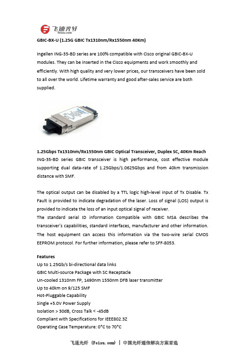
GBIC-BX-U(1.25G GBIC Tx1310nm/Rx1550nm40Km)Ingellen ING-35-BD series are100%compatible with Cisco original GBIC-BX-U modules.They can be inserted in the Cisco equipments and work smoothly and efficiently.With high quality and very lower prices,our transceivers have been sold to all over the world.Lifetime warranty and good after-sales service are both supplied.1.25Gbps Tx1310nm/Rx1550nm GBIC Optical Transceiver,Duplex SC,40Km Reach ING-35-BD series GBIC transceiver is high performance,cost effective module supporting dual data-rate of1.25Gbps/1.0625Gbps and from40km transmission distance with SMF.The optical output can be disabled by a TTL logic high-level input of Tx Disable.Tx Fault is provided to indicate degradation of the laser.Loss of signal(LOS)output is provided to indicate the loss of an input optical signal of receiver.The standard serial ID information Compatible with GBIC MSA describes the transceiver’s capabilities,standard interfaces,manufacturer and other information. The host equipment can access this information via the two-wire serial CMOS EEPROM protocol.For further information,please refer to SFF-8053.FeaturesUp to1.25Gb/s bi-directional data linksGBIC Multi-source Package with SC ReceptacleUn-cooled1310nm FP,1490nm1550nm DFB laser transmitterUp to40km on9/125SMFHot-Pluggable CapabilitySingle+5.0V Power SupplyIsolation>30dB,Cross Talk<-45dBCompliant with Specifications for IEEE802.3ZOperating Case Temperature:0°C to70°CApplicationsGigabit EthernetFiber ChannelWDM ApplicationSpecificationForm Factor BIDI GBIC Distance40km Data Rate 1.25G Low End Case Temperature(°C)0°C High End Case Temperature(°C)70°C Diagnostics Digital Transmitter DFB Receiver PIN Wavelength(nm)1310/1550 Connector SC。
光模块技术参数
光模块的技术参数2007-12-06 17:151、光模块传输数率:指每秒传输比特数,单位Mb/s或Gb/s。
2、光模块发射光功率和接收灵敏度:发射光功率指发射端的光强,接收灵敏度指可以探测到的光强度。
两者都以dBm为单位,是影响传输距离的重要参数。
光模块可传输的距离主要受到损耗和色散两方面受限。
损耗限制可以根据公式:损耗受限距离=(发射光功率-接收灵敏度)/光纤衰减量来估算。
光纤衰减量和实际选用的光纤相关。
一般目前的光纤可以做到1310nm波段km,1550nm 波段km甚至更佳。
50um多模光纤在850nm波段4dB/km 1310nm波段2dB/km。
对于百兆、千兆的光模块色散受限远大于损耗受限,可以不作考虑。
3、10GE光模块遵循的标准,传输的距离和选用光纤类型、光模块光性能相关。
4、饱和光功率值指光模块接收端最大可以探测到的光功率,一般为-3dBm。
当接收光功率大于饱和光功率的时候同样会导致误码产生。
因此对于发射光功率大的光模块不加衰减回环测试会出现误码现象。
5、传输距离光模块的传输距离分为短距、中距和长距三种。
一般认为2km及以下的为短距离,10~20km的为中距离,30km、40km及以上的为长距离。
光模块的传输距离受到限制,主要是因为光信号在光纤中传输时会有一定的损耗和色散。
损耗是光在光纤中传输时,由于介质的吸收散射以及泄漏导致的光能量损失,这部分能量随着传输距离的增加以一定的比率耗散。
色散的产生主要是因为不同波长的电磁波在同一介质中传播时速度不等,从而造成光信号的不同波长成分由于传输距离的累积而在不同的时间到达接收端,导致脉冲展宽,进而无法分辨信号值。
因此,用户需要根据自己的实际组网情况选择合适的光模块,以满足不同的传输距离要求。
6、中心波长中心波长指光信号传输所使用的光波段。
目前常用的光模块的中心波长主要有三种:850nm波段、1310nm波段以及1550nm波段850nm波段:多用于短距离传输1310nm和1550nm波段:多用于中长距离传输光纤光模块应用特性和检测参数值的参考1引言今天,以太网技术已成为局域网中不可或缺、暂时还无可取代的技术。
思科GLC-LH-SM SFP光模块详解
SFP 光模块和传统光模块相比,更容易维护,并且能以高达5Gbps 的速度进行数据传输。
飞速光纤()将在本文中重点介绍Cisco GLC-LH-SM SFP 光模块。
1、SFP 光模块介绍SFP 光模块支持通信标准,包括同步光网络(SONET)/同步数字体系(SDH),千兆以太网和光纤通道。
它们还允许通过基于时分复用的WAN 以太网和千兆以太网LAN 数据包,以及通过分组交换网络传输E1/T1流。
SFP 光模块具有多种可分离的多模和单模光纤接口,允许用户根据网络所需的通信范围选择合适的光模块。
SFP 光模块的信号传输速率范围是100Mbps 到4Gbps,这些SFP 光模块的传输距离在500m 到100km 之间,SFP 光模块的工作波长通常为850nm,1310nm 和1550nm。
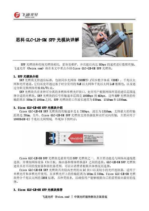
2、Cisco GLC-LH-SM SFP 光模块介绍Cisco GLC-LH-SM SFP 光模块的传输速率是1.25Gbps,波长为1310nm,支持最大的传输距离是20km。
另外,Cisco GLC-LH-SM SFP 光模块支持热插拔和双纤双向传输,主要应用于1000BASE-LX千兆以太网领域,外观如下图所示。
Cisco GLC-LH-SM SFP 光模块是最常用的SFP 光模块之一,其主要功能是与网络高速线缆连接,并增加网络设备(如主板,路由器和媒体转换器)之间的连接。
GLC-LH-SM SFP 光模块通常具有不同的发射器和接收器类型,可以让消费者根据具体情况而选择。
Cisco GLC-LH-SM SFP 光模块具有较高密度的双LC 接口以及较小的光纤连接器,适用于单模光纤和多模光纤使用,在多模光纤上的传输距离为10km 或550m。
Cisco GLC-LH-SM 光模块符合千兆以太网的IEEE 标准,且种类很多,以确保用户能够根据自己的需要做出最好的选择。
3、Cisco GLC-LH-SM SFP 光模块推荐思科GLC-LH-SM SFP 光模块详解产品型号产品名称GLC-LH-SM-20思科(Cisco)GLC-LH-SM-20SFP千兆光模块GLC-LH-SM思科(Cisco)GLC-LH-SM SFP千兆光模块结论Cisco GLC-LH-SM SFP光模块可以兼容其它主要品牌的网络设备。
CISCO路由器光接口类型及光功率汇总
GBIC模块
参数如下:
型号
波长(nm)
光纤类型
距离(km)
WS-G5484 1000BASE-SX
光纤通信基础知识 Cisco设备常用光接口介绍 光纤配件简介
光纤的结构
纤芯
包层
保护套
光纤的结构
纤芯 core:折射率较高,用来传送光; 包层 coating:折射率较低,与纤芯一起形成全反射条件; 保护套 jacket:强度大,能承受较大冲击,保护光纤。 3mm光缆 橘色 MM 黄色 SM
1310
单模
· 10 km (10 Gigabit Ethernet) · 2 km (OC-192/STM-64 SR-1)
XFP-10GER-OC192IR
1550
单模
· 40 km*** (10 Gigabit Ethernet) · 40 km (OC-192/STM-64 IR-2)
2. 2.5G光口: ; 图片如下: 参数如下:
光纤的分类
按照光纤的模式分类 单模(Single-Mode) 多模(Multi-Mode) 按折射率分类 阶越光纤 渐变折射率光纤
光纤的损耗
1310 nm : 0.35 ~ 0.5 dB/Km 1550 nm : 0.2 ~ 0.3dB/Km 850 nm : 2.3 ~ 3.4 dB/Km 光纤熔接点损耗:0.2dB/点 光纤熔接点 1点/2km
光缆 干线缆(架空光缆,直埋光缆,海底光缆,复合光缆……)96芯以下 局内光缆 芯数少,比光线缆柔软 用户缆 根据需要几百芯或几千芯,纤芯为带状光纤
常用连接器类型
SC LC MT-RJ DSC VF-45 Opti-Jack
损耗特性与光的工作波长有关,在三个工作窗口有相对小的损耗: 第一窗口光工作波长0.85μm,损耗稍大 第二窗口光工作波长1.31μm,损耗中等 第三窗口光工作波长1.55μm,损耗最小
思科(Cisco) X2光模块大全
思科(Cisco)X2光模块大全
X2是从Xenpak标准演进而来的,其内部功能模块与Xenpak以及在电路板上的应用基本相同,在实现10G以太网光接口的功能方面都是只使用一个模块即可。
由于Xenpak光模块安装到电路板上时在电路板上的操作比较复杂,且无法实现高密度应用。
而经过改进的X2光模块(其体积只有Xenpak的一半左右)可以直接放到电路板上,因此适用于高密度的机架系统和PCI 网卡应用。
X2光模块是10G光模块中主要的一类封装模块,由XENPAK发展而来。
X2光模块支持热插拔,是一种输入/输出设备配件,主要用于以太网X2端口的交换机和路由器与网络连结端口。
常见的X2光模块有10G X2、BIDI X2、CWDM X2、DWDM X2几种类型。
下面,就为大家介绍几款应用非常广泛的X2系列光模块。
220m
一、思科(Cisco)X2-10GB-LRM X2万兆光模块1310nm
三、思科(Cisco)CWDM-X210G-40L CWDM X2万兆光模块1590nm40km
四、思科(Cisco)DWDM-X210G-40DWDM X2万兆光模块1534.25nm40km
以上就是几款X2系列光模块的简单介绍。
飞速光纤()供应供应一系列X2光模块,可与思科(Cisco)、华为(Huawei)、戴尔(Dell)、华三(H3C)、极进(Extreme)等众多品牌厂家的交换机、路由器、服务器、防火墙产品完全兼容,更多详情请访问飞速光纤官网。
更多详情,请访问飞速光纤官网。
Cisco 6807-XL 和6500-E 系列交换机的高密度多速率万兆接口模块
产品手册Cisco 6807-XL 和 6500-E 系列交换机的高密度多速率万兆接口模块千兆以太网模块为园区集群和核心交换机中的带宽密集型应用实现安全和可预测的性能。
产品概述Cisco Catalyst® 6800 系列交换机提供各种万兆以太网模块。
与 Catalyst® 6500-E/6807-XL 管理引擎 2T/2TXL(VS-S2T-10G 和 VS-S2T-10GXL)配合使用,它们可满足园区部署的不同需求。
该系列包括三种模块:Catalyst6800 32 端口、16 端口和 8 端口万兆以太网光纤模块。
这些模块支持基于硬件的组播复制、服务质量 (QoS)、访问控制列表 (ACL)、巨帧和低延迟,以针对带宽密集型应用实现安全和可预测的性能。
所有三种模块均采用通用的 ASIC 架构且支持相同的硬件功能集。
它们支持小型封装热插拨 (SFP/SFP+)、10/100/1000M GLC-T(1G 铜缆 SFP)收发器和 100M FX。
这些模块可满足园区部署中不断增长的万兆以太网流的汇聚需求,以及对核心中的高密度万兆以太网传输的需求。
这些模块均包括端口组,每个组由八个端口组成。
32 端口和 16 端口模块可在以下两种模式之一中运行:1) 超订用模式(默认),该模式实现最大端口密度,通过 2:1 超订用来使用所有端口;以及 2) 性能模式,该模式使用一半端口,支持线速及使端口缓冲区大小加倍。
每八个端口所组成端口组(混合模式)的运行模式可更改,将在后续章节中更详细地说明。
八端口万兆以太网模块始终在性能模式中运行。
这些模块基于 WS-X6904-40G 模块,并提供相同水平的高级企业功能和大表功能,已被证明是园区汇聚或核心交换机成功运营至关重要。
它们包括硬件功能,例如虚拟交换系统 (VSS)、即时接入 (IA)、位置 ID 分离协议 (LISP)、安全组标记 (SGT) 和访问控制 (SGACL)、MACsec (802.1ae)、流量整形和分层服务质量 (HQoS) 等等。
思科交换机型号字母代表的意思
思科交换机型号字母代表的意思例子:Cisco ws-C3750-24TS-SCisco ws-C2918-24TT-CCisco ws-C2960-24LC-S解释:T-----------主要端口是电口,P-----------主要端口是电口,带Poe以太网供电功能TT----------主要端口和上联口都是电口TC---------主要端口是电口,上联口是电口或SFP光模块TS---------主要端口是电口,上联口是SFP模块LC---------主端口是电口,部分支持Poe(4个),上联口是电口或SFP模块PC---------主端口是电口,支持全部端口Poe,上联口是电口或SFP模块PS---------主端口是电口,支持全部端口Poe,上联口是SFP模块Poe:power on ethernet,以太网供电技术,就是网口有两根线有电,可以给你接的设备供电,一般是IP电话和无线AP.补充:思科交换机的命名一般是WS开头这个是固定的,再下一个字母有两种一个是C一个是X,C代表固化交换机或者机箱,X代表的是模块。
比如看到WS- C3750-24TS-S这个型号的时候我们应该知道他是CISCO交换机.固化交换机3750系列,24个以太网口,TS表示是以太口+SFP口后面的S表示是标准版的,相应的型号就是E的,属于增强型或者叫企业版。
再如WS-X6748-SFP,WS还是代表交换设备,x表示模块,6表示6000系列,7表示7代产品,48表示48口,SFP表示端口类型(SFP是一种mini接口模块)Cisco交换机有以下几个系列:1900系列:19242900系列:2924、2924M2950系列:2950-24、2950G-24/48、2950C-24、2950T-24、2950SX-24/482960系列:2960-24/48TT-L、296024/48TC-L3500系列:3508G、3524、35483550系列:3550-24-SMI/EMI、3550-48-SMI/EMI、3550-12G/T3560系列:3560-24/48也有带G的3750系列:3750-24/48-TS-S、3750-24/48-TS-E 3750G-24/48-TS-S、3750G-24/48-TS-E 、3750G-12S 4000系列:4003、40064500系列:4503、4506、4507R6000系列:6006、60096500系列:6506、6509、6513。
- 1、下载文档前请自行甄别文档内容的完整性,平台不提供额外的编辑、内容补充、找答案等附加服务。
- 2、"仅部分预览"的文档,不可在线预览部分如存在完整性等问题,可反馈申请退款(可完整预览的文档不适用该条件!)。
- 3、如文档侵犯您的权益,请联系客服反馈,我们会尽快为您处理(人工客服工作时间:9:00-18:30)。
Cisco光模块思科光模块以下是思科光模块的产品型号,以及思科光模块各型号对应主要参数描述。
深圳乘光网络通信有限公司,可生产以下兼容光模块产品,可具体兼容到各个型号,价格优惠,欢迎来电来信咨询。
公司网址:/宣传网站:/Table 1. SONET/SDH SFP ModulesProduct ID Product Description ExW inUSD ApplicableStandardTemperatureRange (°C)NoteONS-SE-2G-S1 SFP 2.5G 1310nm SMF 15km DDMPout=-10~-3dBm;Pin=-18dBm GR253 OC48 SRG.957 I-16–10 to +85ONS-SE-2G-L2 SFP 2.5G 1550nm SMF 80km DDMPout=-3~2dBm;Pin=-28dBm GR253 OC48 LR2G.957 L-16.2–10 to +85ONS-SI-155-SR-MM SFP 155M 1310nm MMF 2km DDMPout=-20~14dBm;Pin=-30dBmGR253 –40 to +85ONS-SI-155-I1 SFP 155M 1310nm SMF 10km DDMPout=-15~-8dBm;Pin=-28dBm GR253 OC3 IR1G.957 S-1.1–40 to +85ONS-SI-155-L1 SFP 155M 1310nm SMF 40km DDMPout=-5~-0dBm;Pin=-34dBm GR253 OC3 LR1G.957 L-1.1–40 to +85ONS-SI-155-L2 SFP 155M 1550nm SMF 80km DDMPout=-5~-0dBm;Pin=-34dBm GR253 OC3 LR2G.957 L-1.2–40 to +85ONS-SI-622-SR-MM SFP 622M 1310nm MMF 2km DDMPout=-20~14dBm;Pin=-26dBmGR253 –40 to +85ONS-SI-622-I1 SFP 622M 1310 nm SMF 15km DDMPout=-15~-8dBm;Pin=-28dBm GR253OC3/OC12IR1 G.957 S-4.1/S-1.1–40 to +85ONS-SI-622-L1 SFP 622M 1310 nm SMF 40km DDMPout=-3~2dBm;Pin=-28dBm GR253 OC12 LR1G.957 L-4.1–40 to +85ONS-SI-622-L2 SFP 622M 1550 nm SMF 80km DDMPout=-3~2dBm;Pin=-28dBm GR253 OC12 LR2G.957 L-4.2–40 to +85ONS-SI-2G-S1 SFP 2.5G 1310 nm MMF 2km DDMPout=-10~-3dBm;Pin=-18dBm GR253 OC48 SRG.957 I-16–40 to +85ONS-SI-2G-I1 SFP 2.5G 1310 nm SMF 15km DDMPout=-5~-0dBm;Pin=-18dBm GR253 OC48 IR1G.957 S-16.1–40 to +85ONS-SI-2G-L1 SFP 2.5G 1550 nm SMF 40km DDMPout=-3~2dBm;Pin=-27dBm GR253 OC48 LR1G.957 L-16.1–40 to +85ONS-SI-2G-L2 SFP 2.5G 1550 nm SMF 80km DDMPout=-3~2dBm;Pin=-28dBm GR253 OC48 LR2G.957 L-16.2–40 to +85Table 2. Data SFP ModulesProduct ID Product Description ExW inUSD Applicable StandardTemperatureRange (°C)NoteONS-SE-100-LX10 SFP 100M 1310 nm SMF 10km DDMPout=-15~-8dBm;Pin=-28dBm 100Base LX IEEE-802.3–10 to +85ONS-SI-100-LX10 SFP 100M 1310 nm SMF 10km DDMPout=-15~-8dBm;Pin=-28dBm 100Base LX IEEE-802.3–40 to +85ONS-SE-100-FX SFP 100M 1310 nm MMF 2km DDMPout=-20~14dBm;Pin=-31dBm 100Base FX IEEE-802.3–10 to +85ONS-SI-100-FX SFP 100M 1310 nm MMF 2km DDMPout=-20~14dBm;Pin=-31dBm 100Base FX IEEE-802.3–40 to +85ONS-SE-100-BX10U SFP 100M Tx:1310nm,RX:1490/1550nm DDMPout=-14~-8dBm;Pin=-28.2dBm 100Base BX-U IEEE-802.3–10 to +85ONS-SE-100-BX10D SFP 100M Tx:1490/1550nm,RX:1310nm DDMPout=-14~-8dBm;Pin=-28.2dBm 100Base BX-D IEEE-802.3–10 to +85ONS-SC-GE-SX SFP 1.25G 850nm MMF 550m DDMPout=-9.5~-0dBm;Pin=-17dBm 1000Base SX IEEE-802.30 to +70ONS-SI-GE-SX SFP 1.25G 850nm MMF 550m DDMPout=-9.5~0dBm;Pin=-17dBm 1000Base SX IEEE-802.3–40 to +85ONS-SC-GE-LX SFP 1.25G 1310nm SMF 10km DDMPout=-9.5~-3dBm;Pin=-19dBm 1000Base LX IEEE-802.30 to +70ONS-SI-GE-LX SFP 1.25G 1310nm SMF 10km DDMPout=-9.5~-3dBm;Pin=-19dBm 1000Base SX IEEE-802.3–40 to +85ONS-SE-G2F-SX SFP GE/1G-FC/2G-FC 850nm MMF 550m DDMPout=-9.5~0dBm;Pin=-17dBm 1000BaseSXIEEE-802.3,100-M5-SN-I 100-M6-SN-I200-M5-SN-I 200-M6-SN-I–10 to +85ONS-SE-G2F-LX SFP GE/1G-FC/2G-FC 1310nm SMF 10kmDDMPout=-9.5~-3dBm;Pin=-19dBm 1000BaseLXIEEE-802.3,100-SM-LC-L 200-SM-LC-L–10 to +85ONS-SI-GE-ZX SFP 1.25G 1550nm SMF 80km DDMPout=-0~5dBm;Pin=-23dBm 1000Base ZX IEEE-802.3–40 to +85ONS-SE-GE-ZX SFP 1.25G 1550nm SMF 80km DDMPout=-0~5dBm;Pin=-23dBm 1000Base ZX IEEE-802.3–10 to +85ONS-SE-4G-MM SFP 4G 850nm MMF 550m DDMPout=-9~-3.5dBm;Pin=-15dBm 400-M5-SN-I and 400-M6-SN-I–10 to +85ONS-SE-4G-SM SFP 4G 1310nm SMF 10km DDMPout=-8.4~-3dBm;Pin=-15dBm 400-SM-LC-L–10 to +85Electrical SFP ModulesProduct ID Product Description ExW inUSDApplicableStandardTemperatureRange (°C)NoteONS-SE-ZE-EL SFP – 10/100/1000 Ethernet BaseTMultirate Copper RJ-45IEEE-802.3 –10 to +85ONS-SC-155-EL SFP – STM1 Electrical ITU-T G.703 (ES1) 0 to +70 Multirate SFP ModulesProduct ID Product Description ExW inUSDApplicableStandardTemperatureRange (°C)NoteONS-SE-Z1 SFP 2.5G 1310nm SFM 15km DDMPout=-5~0dBm;Pin=-18dBm(OC-48/STM-16)Pin=-22 (GE)Pin=-23 (OC-12/STM-4)/ (OC-3/STM-1) 1000BaseLXIEEE-802.3,GR253 OC48 IR1OC12 SR ,OC3 SRG.957 S-16.1,I-4.1,I-1.1–10 to +85CWDM SFP ModulesProduct ID Product Description ExW in USD Applicable Standard TemperatureRange (°C)NoteONS-SE-155-1470 SFP 155M 1470nm SMF 80km DDMPout=0~5dBm;Pin=-34dBmITU-T G.694.2 –10 to +85ONS-SE-155-1490 SFP 155M 1490nm SMF 80km DDMPout=0~5dBm;Pin=-34dBmITU-T G.694.2 –10 to +85ONS-SE-155-1510 SFP 155M 1510nm SMF 80km DDMPout=0~5dBm;Pin=-34dBmITU-T G.694.2 –10 to +85ONS-SE-155-1530 SFP 155M 1530nm SMF 80km DDMPout=0~5dBm;Pin=-34dBmITU-T G.694.2 –10 to +85ONS-SE-155-1550 SFP 155M 1550nm SMF 80km DDMPout=0~5dBm;Pin=-34dBmITU-T G.694.2 –10 to +85ONS-SE-155-1570 SFP 155M 1570nm SMF 80km DDMPout=0~5dBm;Pin=-34dBmITU-T G.694.2 –10 to +85ONS-SE-155-1590 SFP 155M 1590nm SMF 80km DDMPout=0~5dBm;Pin=-34dBmITU-T G.694.2 –10 to +85ONS-SE-155-1610 SFP 155M 1610nm SMF 80km DDMPout=0~5dBm;Pin=-34dBmITU-T G.694.2 –10 to +85ONS-SE-622-1470 SFP 622M 1470nm SMF 80km DDMPout=0~5dBm;Pin=-28dBmITU-T G.694.2 –10 to +85ONS-SE-622-1490 SFP 622M 1490nm SMF 80km DDMPout=0~5dBm;Pin=-28dBmITU-T G.694.2 –10 to +85ONS-SE-622-1510 SFP 622M 1510nm SMF 80km DDMPout=0~5dBm;Pin=-28dBmITU-T G.694.2 –10 to +85ONS-SE-622-1530 SFP 622M 1530nm SMF 80km DDMPout=0~5dBm;Pin=-28dBmITU-T G.694.2 –10 to +85ONS-SE-622-1550 SFP 622M 1550nm SMF 80km DDMPout=0~5dBm;Pin=-28dBmITU-T G.694.2 –10 to +85ONS-SE-622-1570 SFP 622M 1570nm SMF 80km DDMPout=0~5dBm;Pin=-28dBmITU-T G.694.2 –10 to +85ONS-SE-622-1590 SFP 622M 1590nm SMF 80km DDMPout=0~5dBm;Pin=-28dBmITU-T G.694.2 –10 to +85ONS-SE-622-1610 SFP 622M 1610nm SMF 80km DDMPout=0~5dBm;Pin=-28dBmITU-T G.694.2 –10 to +85ONS-SC-Z3-1470 SFP 1.25G 1470nm SMF 80km DDMPout=0~4dBm;Pin=-28dBmITU-T G.694.2 0 to +70ONS-SC-Z3-1490 SFP 1.25G 1490nm SMF 80km DDMPout=0~4dBm;Pin=-28dBmITU-T G.694.2 0 to +70ONS-SC-Z3-1510 SFP 1.25G 1510nm SMF 80km DDMPout=0~4dBm;Pin=-28dBmITU-T G.694.2 0 to +70ONS-SC-Z3-1530 SFP 1.25G 1530nm SMF 80km DDMPout=0~4dBm;Pin=-28dBmITU-T G.694.2 0 to +70ONS-SC-Z3-1550 SFP 1.25G 1550nm SMF 80km DDMPout=0~4dBm;Pin=-28dBmITU-T G.694.2 0 to +70ONS-SC-Z3-1570 SFP 1.25G 1570nm SMF 80km DDMPout=0~4dBm;Pin=-28dBmITU-T G.694.2 0 to +70ONS-SC-Z3-1590 SFP 1.25G 1590nm SMF 80km DDMPout=0~4dBm;Pin=-28dBmITU-T G.694.2 0 to +70ONS-SC-Z3-1610 SFP 1.25G 1610nm SMF 80km DDMPout=0~4dBm;Pin=-28dBmITU-T G.694.2 0 to +70 XFP List and Description Grey XFP ModulesProduct ID Product Description ExW inUSD Applicable StandardTemperatureRange (°C)NoteONS-XC-10G-S1 XFP 10G 1310nm SMF 10km DDMPout=-6~1dBm(-8.2~0.5dBm);Pin=-11dBm(-14.4dBm) ITU G694 I-64.1 GR253SR-1 10GE BASE LR1200-SM-LL-L0 to +70ONS-XC-10G-I2XFP 10G 1550nm SMF 40km ITU G694 S-64.2b0 to +70Pout=-1~2dBm;Pin=-14dBm GR253IR-2ONS-XC-10G-L2 XFP 10G 1550nm SMF 80kmPout=0~4dBm;Pin=-24dBm ITU G959.1 P1L1-2D2GR253 LR-20 to +70DWDM XFP ModulesNote:” XX.X”ranges from 30.3 to 61.4.Product ID Product Description ExW inUSD Applicable StandardTemperatureRange (°C)NoteONS-XC-10G-XX.X XFP 10G 15XX.X SMF 80km DDMPout=-1~3dBmITU G694, GR2918 0 to +70 GLC ModulesProduct ID Product Description ExW inUSD Applicable StandardTemperatureRange (°C)NoteGLC-FE-100FX SFP 155M 1310nm MMF 2kmPout= -8~-15dBm ; Pin= -30dBm FastEthernet;SDH/STM-1; OC3 SR0 to 75GLC-FE-100LX SFP 155M 1310nm SMF 10kmPout= -8~-15dBm ; Pin= -30dBm Fast Ethernet; SDH/STMI-1; OC3 IR10 to 75GLC-FE-100EX SFP 155M EX 1310nm SMF 40kmPout= -8~-15dBm ; Pin= -28dBm Fast Ethernet; SDH/STML-1.1; OC3 LR10 to 75GLC-FE-100ZX SFP 155M 1550nm SMF 80kmPout= -5~0dBm ; Pin= -32dBm Fast Ethernet; SDH/STML-1.2; OC3 LR20 to 75GLC-FE-100FX-RGD SFP 155M 1310nm MMF 2kmPout= -8~-15dBm ; Pin= -30dBm FastEthernet;SDH/STM-1; OC3 SR-40 to 85GLC-FE-100LX-RGD SFP 155M 1310nm SMF 10kmPout= -8~-15dBm ; Pin= -30dBm Fast Ethernet; SDH/STMI-1; OC3 IR1-40 to 85GLC-FE-100EX-RGD SFP 155M EX 1310nm SMF 40kmPout= -8~-15dBm ; Pin= -28dBm Fast Ethernet; SDH/STML-1.1; OC3 LR1-40 to 85GLC-FE-100BX-D SFP 100M Tx: 1550nm,RX: 1310nm 20km Fast Ethernet; SDH/STMI-1.1; OC3 IR10 to 75GLC-FE-100BX-U SFP 100M Tx:1310nm,RX: 1550nm 20km Fast Ethernet; SDH/STMI-1.1; OC3 IR10 to 75GLC-SX-MM SFP 1.25G 850nm MMF 550mPout= -3~-9dBm ; Pin= -18dBm 1.25G1000BaseSX;1.06G FC SX0 to 75GLC-LH-SM SFP 1.25G 1310nm SMF 10kmPout= -3~-9dBm ; Pin= -20dBm 1.25G1000BaseLX;1.06G FC LX0 to 75GLC-EX-SMD SFP 1.25G 1310nm SMF 40km DDMPout= -5~0dBm ; Pin= -22dBm 1.25G1000BaseEX;1.06G FC EX0 to 75GLC-ZX-SM SFP 1.25G 1550nm SMF 80kmPout= 0~5dBm ; Pin= -23dBm 1.25G1000BaseZX;1.06G FC ZX0 to 75GLC-T SFP 100M/1000M TX 100m max 1.25G 1000BaseTX 0 to 75GLC-SX-MM-RGD SFP 1.25G 1310nm SMF 10kmPout= -3~-9dBm ; Pin= -20dBm 1.25G1000BaseLX;1.06G FC LX-40 to 85GLC-LH-SM-RGD SFP 1.25G 1310nm SMF 40km DDMPout= -5~0dBm ; Pin= -22dBm 1.25G1000BaseEX;1.06G FC EX-40 to 85GLC-ZX-SM-RGD SFP 1.25G 1550nm SMF 80kmPout= 0~5dBm ; Pin= -23dBm 1.25G1000BaseZX;1.06G FC ZX-40 to 85CWDM-SFP-**** SFP1.25GCWDM 1XX0nm SMF 80kmDDM Pout= 0~5dBm ; Pin= -23dBm 1.25G1000BaseCWDM;1.06G FC CWDM0 to 75GLC-BX-D SFP 1000M Tx: 1550nm,RX: 1310nm20km 1.25G1000BaseLX;1.06G FC LX0 to 75GLC-BX-U SFP 1000M Tx:1310nm,RX: 1550nm20km 1.25G1000BaseLX;1.06G FC LX0 to 75XFP-10G-MM-SR XFP 10G SR/SW 850nm MMF 300m DDMPout= -5~-1dBm ; Pin= -11dBm 10GBase SR/SW 10GE;SDH/STM64 OC1920 to 75XFP-10GLR-OC192S R XFP 10G LR/LW 1310nm SMF 10kmDDM Pout= -6~-1dBm ; Pin= -13dBm10GBase LR/LW 10GE;SDH/STM64 OC1920 to 75XFP-10GER-192IR XFP 10G ER/EW 1550nm SMF 40kmDDM Pout= -1~2dBm ; Pin= -16dBm 10GBase ER/EW 10GE;SDH/STM64 OC1920 to 75XFP-10GZR-OC192L R XFP 10G ZR/ZW 1550nm SMF 80kmDDM Pout= 0~4dBm ; Pin= -23dBm10GBaseZR/ZW10GE;SDH/STM64 OC1920 to 75DWDM-XFP-**** DWDM XFP C-Band SMF 80km DDMPout= 0~4dBm ; Pin= -23dBm 10GBaseZR/ZW10GE;SDH/STM64 OC1920 to 75XENPAK-10GB-SR Xenpak 10G SR 850nm MMF 85m DDMPout= -5~-1dBm ; Pin= -11dBm 10GBase SR 10GEthernet0 to 75XENPAK-10GB-LR Xenpak 10G LR 1310nm SMF 10km DDMPout= -8~0dBm ; Pin= -12dBm 10GBase LR 10GEthernet0 to 75XENPAK-10GB-LR+ Xenpak 10G LR 1310nm SMF 10km DDMPout= -8~0dBm ; Pin= -12dBm 10GBase LR 10GEthernet0 to 75X2-10GB-SR X2 10G SR/SW 850nm MMF 85m DDMPout= -5~-1dBm ; Pin= -11dBm 10GBase SR/SW 10GEthernet0 to 75X2-10GB-LR X2 10G LR/LW 1310nm SMF 10km DDMPout= -8~0dBm ; Pin= -11dBm 10GBase LR/LW 10GEthernet0 to 75X2-10GB-LRM X2 10G LRM 1310nm MMF 220m DDMPout= -6~0dBm ; Pin= -8dBm 10GBaseLRM10GEthernet0 to 75X2-10GB-ER X2 10G ER/EW 1550nm SMF 40km DDMPout=-4~4dBm ; Pin= -16dBm 10GBase ER/EW 10GEthernet0 to 75SFP-10G-SR SFP+ 10G SR/SW 850nm MMF 300mDDM Pout= -9~-1dBm ; Pin= -13dBm 10GBase SR/SW 10GEthernet0 to 75SFP-10G-LR SFP+ 10G LR/LW 1310nm SMF 10kmDDM Pout= -8~0dBm ; Pin= -14dBm 10GBase LR/LW 10GEthernet0 to 75SFP OC ModulesProduct ID Product Description ExW inUSD Applicable StandardTemperatureRange (°C)NoteSFP-OC3-MM OC-3/STM-1 SFP 2 km 1310nm MMF FastEthernet;SDH/STM-1; OC3 SR0 to 75SFP-OC3-SR SFP 155M 1310nm MMF 2kmPout= -8~-15dBm ; Pin= -30dBm FastEthernet;SDH/STM-1; OC3 SR0 to 75SFP-OC3-IR1 SFP155M 1310nm SMF 10kmPout= -8~-15dBm ; Pin= -30dBm Fast Ethernet; SDH/STMI-1; OC3 IR10 to 75SFP-OC3-LR1 SFP 155M EX 1310nm SMF 40kmPout= -8~-15dBm ; Pin= -28dBm Fast Ethernet; SDH/STML-1.1; OC3 LR10 to 75SFP-OC3-LR2 SFP 155M 1550nm SMF 80kmPout= -5~0dBm ; Pin= -32dBm Fast Ethernet; SDH/STML-1.2; OC3 LR20 to 75SFP-OC12-MM OC-12/STM-4 SFP 2 km 1310nm MMF SDH/STMS-4.1I-4;OC12, SR0 to 75 SFP-OC12-SR OC-12/STM-4 SFP 2 km 1310nm MMF SDH/STMS-4.1I-4;OC12, SR0 to 75SFP-OC12-IR1 SFP 622M IR 1310nm SMF 15kmPout= -8~-15dBm ; Pin= -28dBm SDH/STMS-4.1I-4;OC12 IR-1, SR0 to 75SFP-OC12-LR1 SFP 622M LR1 1310nm SMF 40kmPout= -8~-14dBm ; Pin= -28dBm SDH/STM L-4.1; OC12LR-10 to 75SFP-OC12-LR2 SFP 622M LR2 1550nm SMF 80kmPout= -3~2dBm ; Pin= -28dBm SDH/STM L-4.2; OC12LR-20 to 75SFP-OC48-SR OC-48/STM-16 SFP 2 km 1310nm MMF SDH/STMS-16.1;OC48,SR0 to 75SFP-OC48-IR1 SFP2.5G IR 1310nm SMF 15kmPout= -5~0dBm ; Pin= -20dBm SDH/STMS-16.1;OC48 IR-1, SR0 to 75SFP-OC48-LR1 SFP 2.5G LR1 1550nm SMF 40kmPout= 0~5dBm ; Pin= -20dBm SDH/STML-16.1;OC48LR-10 to 75SFP-OC48-LR2 SFP 2.5G LR2 1550nm SMF 80kmPout= 0~5dBm ; Pin= -30dBm SDH/STML-16.2;OC48LR-20 to 75DS SFP ModulesProduct ID Product Description ExW inUSD Applicable StandardTemperatureRange (°C)NoteDS-SFP-FCGE-SW SFP 1000M SX 850nm MMF 550m DDMPout= -3~-9dBm ; Pin= -18dBm 1.25G1000BaseSX;1.06G FC SX-10 to 85DS-SFP-FCGE-LW SFP 1000M LX 1310nm SMF 10km DDMPout= -3~-9dBm ; Pin= -20dBm 1.25G1000BaseLX;1.06G FC LX-10 to 85DS-SFP-FCGE-EW SFP 1000M EX 1310nm SMF 40km DDMPout= -5~0dBm ; Pin= -22dBm 1.25G1000BaseEX;1.06G FC EX-10 to 85DS-SFP-FCGE-ZW SFP 1000M ZX 1550nm SMF 80km DDMPout= 0~5dBm ; Pin= -23dBm 1.25G1000BaseZX;1.06G FC ZX-10 to 85DS-SFP-FC-2G-SW SFP 2G SX 850nm MMF 550m DDM 2G FC SX -10 to 85 DS-SFP-FC-2G-LW SFP2G LX 1310nm SMF 10km DDM 2G FC LX -10 to 85 DS-SFP-FC-2G-EW SFP 2G EX 1310nm SMF 40km DDM 2G FC EX -10 to 85 DS-SFP-FC-2G-ZW SFP 2G ZX 1550nm SMF 80km DDM 2G FC ZX -10 to 85。