贴片电感DFE201610E-100M 品牌TOKO规格书推荐
插件国巨电阻规格书
Page-1Approval SheetforCarbon Film ResistorsCFR series±2% & ±5%YAGEO CORPORATIONHeadquarters: 3F, No.233-1, Pao Chiao Rd., Shin Tien, Taipei, Taiwan,R.O.C.Tel: 886-2-2917-7555 Fax: 886-2-2917-4286URL: Page-2Page-31. PRODUCT : CARBON FILM RESISTORS(Normal & Miniature Style)2. PART NUMBER : Part number of the carbon film resistor is identified by the name,power, tolerance, packing, temperature coefficient, special type and resistance value.Example :CFR -12 J T J 52 100RSeries Size Resistance Packing Temperature Special ResistanceName Code Tolerance Style Coefficient Type Value of Resistance(1) Style: CFR SERIES(2) Power Rating: -12=1/6W 、25S=1/4WS 、-25=1/4W 、50S=1/2WS 、-50=1/2W 、 1WS=1WS 、100=1W 、2WS=2WS 、200=2W(3) Tolerance: G=±2% J=±5%(4) Packaging Type : R =Paper Taping Reel T =Tape on Box Packing B =Bulk Packing(5) T .C .R : J=±350ppm/℃ — =lgnore(6) Special Type : 26=26mm 、52=52.4mm 、73=73mm 、 PN =PANAsert AV =AVlsert(7) Resistance Value: 1R 、10R 、100R 、10K 、100K 、330K 、1M………Page-43. BAND-CODE:4. ELECTRICAL CHARACTERISTICSTabe I*Standard resistance is 1Ω~ 10M Ω, below or over this resistance on request. *Rated Continuous Working Voltage (RCWV)=Value Resistance Rating Power ×FIG.1 TEMPERATURE COEFFICIENTPage-55. DERATING CURVE & HOT-SPOT TEMPERATURE6. DIMENSIONS7. ENVIRONMENTAL CHARACTERISTICS(1) Short Time Over Load TestAt 2.5 times of the rated voltage. (If the voltage exceeds the maximum load voltage, the maximum load voltage will be used as the rated voltage) applied for 5 seconds, the resistor should be free from defects after the resistor is released from load for about 30 minutes and the change of the resistance value should be within ±(0.25%+0.05Ω) as compared with the value before the test.Page-6(2) Dielectric Withstanding VoltageThe resistor is placed on the metal V Block. Apply a Table I dielectric withstanding between the terminals connected together with the block for about 60 seconds. The resistor shall be able to withstand without breakdown or flashover.(3) Temperature Coefficient TestTest of resistors above room temperature 125°C to 130°C (Testing Temperature) at the constant temperature silicon plate for over 4 to 5 minutes. Then measure the resistance. The Temperature Coefficient is calculated by the following equation and its value should be within the range of requested.600010t t 1R R R t Coefficien e Temperatur sistor Re ×−×−=R= Resistance value under the testing temperature R 0= Resistance value at the room temperature t = The testing temperature t o = Room temperature(4) Insulation ResistanceApply test terminal on lead and resistor body. The test resistance should be high than 10,000 Mohm.(5) SolderabilityImmerse the specimen into the solder pot at 230±5°C for 5±0.5 seconds. At least 95% solder coverage on the termination.(6) Resistance to SolventThe specimen into the appropriate solvent of Methyleme Chloride condition ofultrasonic machine for 1 minutes. The specimen is no deterioration of coatings and color code.(7) Terminal StrengthDirect Load – Resistors shall be held by one terminal and the load shall be gradually applied in the direction of the longitudinal axis of the resistor unit the applied load reacheds 5 pounds. The load shall be held for 10 seconds. The load of weight shall be ≧2.5kg(24.5N).Page-7(8) Pulse OverloadApply 4 times of rated voltage to the specimen at the 1 second on and 25 seconds off cycle, subjected to voltage application cycles specified in 10000. The change of the resistance value shall be within ±(2%+0.05Ω).(9) Load Life in HumidityPlace the specimen in a test chamber at 40±2°C and 90~95% relative humidity. Apply the rated voltage to the specimen at the 1.5 hours on and 0.5 hour off cycle. The total length of test is 1000 hours. The change of the resistance value shall be within ±(1.5%+0.05Ω).(10) Load Life TestPlaced in the constant temperature chamber of 70±3°C the resistor shall be connected to the lead wire at the point of 25mm. Length with each terminal, the resistors shall be arranged not much effected mutually by the temperature of the resistors and the excessive ventilation shall not be performed, for 90 minutes on and 30 minutes off under this condition the rated D.C. voltage is applied continuously for 1000+48/-0 hours then left at no-load for 1hour, the change of the resistance value measured at this time to the value before the test shall be within ±(1.5%+0.05Ω). There shall be no remarkable change in the appearance and the color code shall be legible after the test.(11) Temperature Cycling TestThe temperature cycle shown in the following table shall be repeated 5 times consecutively. The measurement of the resistance value is done before the first cycle and after ending the fifth cycle, leaving in the room temperature for about 1 hour, the change shall be within ±(1%+0.05Ω). After the test the resistor shall be free from the electrical or mechanical damage.Temperature Cycling Conditions: Step Temperature(°C) Time (minute)1 +25+10 -5 10 to152 -65+0 -3 30 3 +25+10 -5 10 to15 4+150+3 -030Page-8(12) Resistance to Soldering HeatThe terminal lead shall be dipped into the solder pot at 350±10°C for 3±0.5 seconds up to 3 mm. The change of the resistance value shall be within ±(1%+0.05Ω).8. PACKING METHODS Bandolier for Axial leadsThe resistors are supplied on bandolier, either 1000 resistors in ammopack or 5000 resistors on reel.9. TAPE ON REEL PACKING & TAPE ON BOX PACKING10. SPECIAL TYPE (FORMING DIMENSIONS)。
PBO系列贴片功率电感规格书

101
【 南京南山半导体有限公司 — 风华高科贴片功率电感选型资料】
PBO5022 Series
Part Number PBO5022-1R0MT PBO5022-2R2MT PBO5022-3R3MT PBO5022-5R6MT PBO5022-100MT PBO5022-150MT PBO5022-220MT PBO5022-330MT PBO5022-470MT PBO5022-680MT PBO5022-101MT PBO5022-151MT PBO5022-221MT PBO5022-331MT PBO5022-471MT PBO5022-681MT PBO5022-102MT L(
贴片功率电感贴片功率电感封装贴片电感规格贴片电感封装贴片电感封装尺寸贴片功率电感价格贴片电感贴片共模电感0805贴片电感贴片电感种类
【 南京南山半导体有限公司 — 风华高科贴片功率电感选型资料】
PBO PBO SERIES SMD POWER INDUCTORS FEATURES
DCR(
)Max
Isat(A) 20 16 14 12 10 8.0 7.0 5.5 4.5 3.5 3.0 2.6 2.4 1.9 1.4 1.2 1.0
0.009 0.014 0.018 0.020 0.031 0.036 0.047 0.066 0.086 0.130 0.190 0.250 0.380 0.560 0.850 1.100 1.800
HOW TO ORDER
PBO 1608 150 M T
(L Product Code (mm)
W T)
(
H)
Tolerance K 10% 20%
Packaging Style T B Tape & Reel Bulk
太诱贴片电感规格书
0.82
15
75
1.40
35
RoHS
1.0
ʶ10ˋ
35
70
0.60
30
RoHS
1.2
ʶ20ˋ
35
60
0.65
30
RoHS
1.5
35
55
0.70
30
RoHS
1.8
35
50
0.95
30
RoHS
2.2
35
45
1.00
30
RoHS
2.7
35
40
1.15
30
ImaxʦmAʧ
50 30 10
RdcmaxʦЊʧ
0.35 0.60 1.70
ImaxʦmAʧ
250 80 15
RdcmaxʦЊʧ
0.15 0.30 0.80
选件指南 Selection Guide
P.14
型号一览 Part Numbers
P.188
特性图 Electrical Characteristics
电感量公差ʤˋʥ
K
ʶ10
M
ʶ20
5
包装
ʵT
卷盘带装
6
本公司管理记号
˚
标准品
˚ʹ空格
LK1 6 0 8 R 1 0 M _ T ˓
1
2
3
4
5
6
1
Type
LK
Multilayer chip inductors
2
External DimensionsʢLʷWʣʤmmʥ
1005ʢ0402ʣ 1.0ʷ0.5 1608ʢ0603ʣ 1.6ʷ0.8 2125ʢ0805ʣ ɹ2.0ʷ1.25
厚生电阻规格书
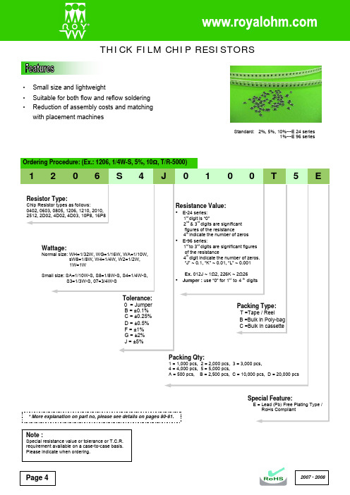
Page 4•Small size and lightweight• Suitable for both flow and reflow soldering •Reduction of assembly costs and matching with placement machines2007 - 2008Standard: 2%, 5%, 10%---E 24 series 1%---E 96 series2007 - 2008 Page 5Marking on the Resistors Body:•For 0402 size, no marking on the body due to the small size of the resistor.•±5% tolerance product. (Including resistance values less than 1Ω; both 1% and 5%) The marking is 3 digits, the first 2 digits are the significant figures of the resistance and the 3rd digit denotes number of zeros.153 = 15000Ω = 15KΩ; 120 = 12Ω Below 10Ω shown as this: 6R8 = 6.8Ω 0.1Ω~0.99Ω shown as this: R33 = 0.33Ω•±1% tolerance marking of case size 0805 and bigger is 4 digits, the first 3 digits are the significant figures of the resistance and the 4th digit denotes number of zeros.2372 = 23700Ω = 23.7KΩ; 1430 = 143Ω Below 10Ω shown as this: 3R24 = 3.24Ω0.1Ω~0.99Ω shown as this: R33 = 0.33ΩPage 62007 - 2008* More details, please see pages 78-79.• Standard E-96 series values (±1% tolerance) of 0603 size. Due to the small size of the resistor’s body, 3 digitsmarking will be used to indicate the accurate resistance value by using the Multiplier code & Standard E-96 Series Resistance Value Code as shown on Page 6.1.96K Ω = 196 x 101 Ω = 29B12.4Ω = 124 x 10-1 Ω = 10X• Standard E-24 series values which does not belong to E-96 series values (in ±1% tolerance) of 0603 size. The marking is the same as 5% tolerance but marked with underline.122 = 1200 = 1.2K Ω680 = 68ΩTemperature coefficient±5%: 1Ω ~ 10M Ω ≤ ±200PPM/°C±1%: 10Ω ~ 100Ω ≤ ±200PPM/°C; 101Ω ~ 1M Ω ≤ ±100PPM/°C Short-time overload ±5%: ±(2.0% + 0.1Ω) Max. ±1%: ±(1.0% + 0.1Ω) Max. Insulation resistanceMin. 1,000 Mega OhmDielectric withstanding voltageNo evidence of flashover, mechanical damage, arcing or insulation breakdown Terminal bending ±(1.0% + 0.05Ω) Max.Soldering heat Resistance change rate is ±(1.0% + 0.05Ω) Max. SolderabilityMin. 95% coverage Temperature cycling ±5%: ±(1.0% + 0.05Ω) Max. ±1%: ±(0.5% + 0.05Ω) Max. Humidity (Steady State) ±5%: ±(3.0% + 0.1Ω) Max. ±1%: ±(0.5% + 0.1Ω) Max. Load life in humidity±5%: ±(3.0% + 0.1Ω) Max. ±1%: ±(1.0% + 0.1Ω) Max. Load life±5%: ±(3.0% + 0.1Ω) Max.±1%: ±(1.0% + 0.1Ω) Max.* The values which are not of standard E-24 series (2% & 5%) and not of E-96 series (1%) could be offered on a case to case basis.2007 - 2008Page 72007 - 2008Page 8•16P8 (16Pin 8R)THICK FILM CHIP RESISTOR ARRAYS• High density 2, 4, 8 resistors in one small case (convex type) • Improvement of placement efficiency• Packaging is suitable for automatic placement machines • Superior solderability • Scalloped•2D02 (4Pin 2R)•4D02, 4D03 (8Pin 4R)•10P8 (10Pin 8R)Part No.StyleLWHℓ1ℓ2PQ2D02 (0402x2) 2D02 (4Pin 2R) 1.0 ± 0.1 1.0 ± 0.1 0.35 ± 0.1 0.17 ± 0.1 0.25 ± 0.1 0.65 ± 0.05 0.33 ± 0.1 4D02 (0402x4) 4D02 (8Pin 4R) 2.0 ± 0.1 1.0 ± 0.1 0.45 ± 0.1 0.2 ± 0.15 0.3 ± 0.15 0.5 ± 0.05 0.3 ± 0.05 4D03 (0603x4) 4D03 (8Pin 4R) 3.2 ± 0.2 1.6 ± 0.2 0.5 ± 0.1 0.3 ± 0.15 0.3 ± 0.15 0.8 ± 0.1 0.5 ± 0.15 16P8 16P8 (16Pin 8R) 4.0 ± 0.2 1.6 ± 0.15 0.45 ± 0.1 0.3 ± 0.15 0.4 ± 0.15 0.5 ± 0.05 0.3 ± 0.05 10P8 10P8 (10Pin 8R)3.2 ± 0.21.6 ± 0.150.55 ± 0.10.4 ± 0.10.3 ± 0.150.64 ± 0.050.35 ± 0.05Resistance RangePart No. StylePower Rating at 70ºC Max. Working Voltage Max. Overload VoltageDielectric With-standing VoltageOperated Temp. RangeF (±1%) E-96 seriesJ (±5%) E-24 seriesJumper Rated Current2D02 2D02 (4Pin2R) 1/16W 50V 100V 500V -55ºC~+155ºC - 10Ω~ 1M Ω - 4D02 4D02 (8Pin4R) 1/16W 50V 100V 500V -55ºC~+155ºC -10Ω~ 1M Ω -4D03 4D03 (8Pin4R) 1/16W 50V 100V 500V -55ºC~+155ºC 100Ω~560K Ω 10Ω~ 1M Ω 1A 16P8 16P8 (16Pin8R) 1/16W 50V 100V 100V -55ºC~+155ºC - 10Ω~ 1M Ω - 10P810P8 (10Pin8R)1/32W 25V 50V 50V -55ºC~+155ºC -33Ω~ 100K Ω -Note: Part number and ordering procedure the same as Thick Film Chip Resistors on Page 4.Standard: 2%, 5%, 10%---E 24 series 1%---E 96 series。
标准电阻阻值表
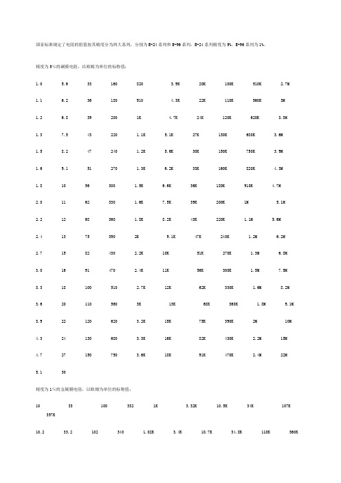
国家标准规定了电阻的阻值按其精度分为两大系列,分别为E-24系列和E-96系列,E-24系列精度为5%,E-96系列为1%。
精度为5%的碳膜电阻,以欧姆为单位的标称值:1.0 5.6 33 160 820 3.9K 20K 100K 510K2.7M1.1 6.2 36 180 910 4.3K 22K 110K 560K 3M1.2 6.8 39 200 1K 4.7K 24K 120K 620K 3.3M1.3 7.5 43 220 1.1K 5.1K 27K 130K 680K 3.6M1.5 8.2 47 240 1.2K 5.6K 30K 150K 750K 3.9M1.6 9.1 51 270 1.3K 6.2K 33K 160K 820K 4.3M1.8 10 56 300 1.5K 6.6K 36K 180K 910K 4.7M2.0 11 62 330 1.6K 7.5K 39K 200K 1M 5.1M2.2 12 68 360 1.8K 8.2K 43K 220K 1.1M 5.6M2.4 13 75 390 2K 9.1K 47K 240K 1.2M 6.2M2.7 15 82 430 2.2K 10K 51K 270K 1.3M 6.8M3.0 16 91 470 2.4K 11K 56K 300K 1.5M 7.5M3.3 18 100 510 2.7K 12K 62K 330K 1.6M 8.2M3.6 20 110 560 3K 13K 68K 360K 1.8M 9.1M3.9 22 120 620 3.2K 15K 75K 390K 2M 10M4.3 24 130 680 3.3K 16K 82K 430K 2.2M 15M4.7 27 150 750 3.6K 18K 91K 470K 2.4M 22M5.1 30精度为1%的金属膜电阻,以欧姆为单位的标称值:10 33 100 332 1K 3.32K 10.5K 34K 107K357K10.2 33.2 102 340 1.02K 3.4K 10.7K 34.8K 110K 360K10.5 34 105 348 1.05K 3.48K 11K 35.7K 113K365K10.7 34.8 107 350 1.07K 3.57K 11.3K 36K 115K 3 74K11 35.7 110 357 1.1K 3.6K 11.5K 36.5K 118K 383 K11.3 36 113 360 1.13K 3.65K 11.8K 37.4K 120K 3 90K11.5 36.5 115 365 1.15K 3.74K 12K 38.3K 121K 3 92K11.8 37.4 118 374 1.18K 3.83K 12.1K 39K 124K 4 02K12 38.3 120 383 1.2K 3.9K 12.4K 39.2K 127K 412 K12.1 39 121 390 1.21K 3.92K 12.7K 40.2K 130K 4 22K12.4 39.2 124 392 1.24K 4.02K 13K 41.2K 133K 4 30K12.7 40.2 127 402 1.27K 4.12K 13.3K 42.2K 137K 432 K13 41.2 130 412 1.3K 4.22K 13.7K 43K 140K442K13.3 42.2 133 422 1.33K 4.32K 14K 43.2K 143K 4 53K13.7 43 137 430 1.37K 4.42K 14.3K 44.2K 147K 4 64K14 43.2 140 432 1.4K 4.53K 14.7K 45.3K 150K 47 0K14.3 44.2 143 442 1.43K 4.64K 15K 46.4K 154K 4 75K14.7 45.3 147 453 1.47K 4.7K 15.4K 47K 158K 48 7K15 46.4 150 464 1.5K 4.75K 15.8K 47.5K 160K 49 9K15.4 47 154 470 1.54K 4.87K 16K 48.7K 162K511K15.8 47.5 158 475 1.58K 4.99K 16.2K 49.9K 165K 523 K16 48.7 160 487 1.6K 5.1K 16.5K 51K 169K 5 36K16.2 49.9 162 499 1.62K 5.11K 16.9K 51.1K 174K 549 K16.5 51 165 510 1.65K 5.23K 17.4K 52.3K 178K 5 60K16.9 51.1 169 511 1.69K 5.36K 17.8K 53.6K 180K 562 K17.4 52.3 174 523 1.74K 5.49K 18K 54.9K 182K 5 76K17.8 53.6 178 536 1.78K 5.6K 18.2K 56K 187K 59 0K18 54.9 180 549 1.8K 5.62K 18.7K 56.2K 191K 60 4K18.2 56 182 560 1.82K 5.76K 19.1K 57.6K 196K 6 19K18.7 56.2 187 562 1.87K 5.9K 19.6K 59K 200K 62 0K19.1 57.6 191 565 1.91K 6.04K 20K 60.4K 205K 6 34K19.6 59 196 578 1.96K 6.19K 20.5K 61.9K 210K 6 49K20 60.4 200 590 2K 6.2K 21K 62K 215K665K20.5 61.9 205 604 2.05K 6.34K 21.5K 63.4K 220K 680 K21 62 210 619 2.1K 6.49K 22K 64.9K 221K681K21.5 63.4 215 620 2.15K 6.65K 22.1K 66.5K 226K 698 K22 64.9 220 634 2.2K 6.8K 22.6K 68K 232K 7 15K22.1 66.5 221 649 2.21K 6.81K 23.2K 68.1K 237K 732 K22.6 68 226 665 2.26K 6.98K 23.7K 69.8K 240K 7 50K23.2 68.1 232 680 2.32K 7.15K 24K 71.5K 243K 7 68K23.7 69.8 237 681 2.37 7.32K 24.3K 73.2K 249K 787K24 71.5 240 698 2.4K 7.5K 24.9K 75K 255K 8 06K24.3 73.2 243 715 2.43K 7.68K 25.5K 76.8K 261K 820 K24.7 75 249 732 2.49K 7.87K 26.1K 78.7K 267K 8 25K24.9 75.5 255 750 2.55K 8.06K 26.7K 80.6K 270K 845 K25.5 76.8 261 768 2.61K 8.2K 27K 82K 274K866K26.1 78.7 267 787 2.67K 8.25K 27.4K 82.5K 280K 887 K26.7 80.6 270 806 2.7K 8.45K 28K 84.5K 287K 90 9K27 82 274 820 2.74K 8.66K 28.7K 86.6K 294K910K27.4 82.5 280 825 2.8K 8.8K 29.4K 88.7K 300K 931K28 84.5 287 845 2.87K 8.87K 30K 90.9K 301K953K28.7 86.6 294 866 2.94K 9.09K 30.1K 91K 309K 9 76K29.4 88.7 300 887 3.0K 9.1K 30.9K 93.1K 316K 1.0M30 90.9 301 909 3.01K 9.31K 31.6K 95.3K 324K 1 .5M30.1 91 309 910 3.09K 9.53K 32.4K 97.6K 330K 2 .2M30.9 93.1 316 931 3.16K 9.76K 33K 100K 332K31.6 95.3 324 953 3.24K 10K 33.2K 102K 340K32.4 97.6 330 976 3.3K 10.2K 33.6K 105K 348K常用电阻阻值:1,1.1,1.2,1.3,1.5,1.6,1.82,2.2,2.4,2.7,3,3.3,3.6,3.94.3,4.75.1,5.66.2,6.87.58.29.110,11,12,13,15,16,1820,22,24,2730,33,36,3943,4751,5662,687582,81100,110,120,130,150 ,160,180 200,220,240,270300,330,360,390430,470510,560620,6807508201K,1.1K,1.2K,1.3K,1.5K,1.6K,1.8K2K,2.2K,2.4K,2.7K3K,3.3K,3.6K,3.9K4.3K,4.7K5.1K,5.6K6.2K,6.8K,7.5K8.2K9.1K10K,11K,12K,13K,15K,16K,18K 20K,22K,24K,27K30K,33K,36K,39K43K,47K51K,56K62K,68K75K82K100K,110K,120K,130K,150K,160K,180K200K,220K,240K,270K,300K,330K,360K,390K430K,470K510K,560K620K,680K750K,820K910K1M,1.1M,1.2M,1.3M,1.5M,1.6M,1.8M2M,2.2M,2.4M,2.7M3M,3.3M,3.6M,3.9M4.4M,4.7M常用电容值:【单位pF】39 P 43 P 47 P 51 P 56 P 62 P 68 P 75 P 82 P 91 P100 P 120 P 150 P180 P 200 P 220 P 240 P 270 P 300 P 330 P 360 P 390 P 470 P 560 P 620 P680 P 750 P【单位nF】1.0 1.2 1.5 1.82.2 2.73.3 3.94.75.6 10 15 18 22 27 3339 56 68 82【单位uF】0.10.15 0.22 0.33 0.47 1.0 (1.5) 2.21、5%精度的命名:RS-05K102JT2、1%精度的命名:RS-05K1002FTR -表示电阻S -表示功率0402是1/16W、0603是1/10W、0805是1/8W、1206是1/4W、 1210是1/3W、1812是1/2W、2010是3/4W、2512是1W。
TOKO电感手册
11. HUMIDITY TEST
The change in inductance, if any, is measured after exposure in a test chamber to humidity of 90% to 95% R.H. at 60 2°C for 500 12 hours and 1 hour exposure at room temperature.
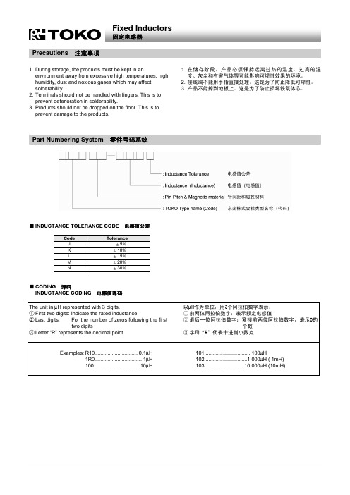
Fixed Inductors
固定电感器
Precautions
注意事项
1. 在储存阶段,产品必须保持远离过热的温度、过高的湿 度、灰尘和有害气体等可能影响可焊性效果的环境。 2. 接线端不能用手指直接处理。这是为了防止降低可焊性。 3. 产品不能掉到地板上。这是为了防止损坏铁氧体芯。
1. During storage, the products must be kept in an environment away from excessive high temperatures, high humidity, dust and noxious gases which may affect solderability. 2. Terminals should not be handled with fingers. This is to prevent deterioration in solderability. 3. Products should not be dropped on the floor. This is to prevent damage to the products.
2. Q FACTOR
The unloaded Q is measured with a Q-meter, LCR meter or impedance analyzer. The frequency of measurement is that at which the inductance has been measured or at a different frequency as specified. However, for high current power line inductors, the resistance is measured and the Q may be neglected.
国巨电容规格书
Conditions
NPO
Requirements
X7R
Y5V
Bending rate 1mm/s, jig. Radius ∆C/C ≤ 1%
∆C/C ≤ 10%
∆C/C ≤ 20%
340mm
260±5°C for 10±0.5s in static ∆C/C ≤ 0.5% or 0.5pF, -5% ≤ ∆C/C ≤ 10% -10% ≤ ∆C/C ≤ 20%
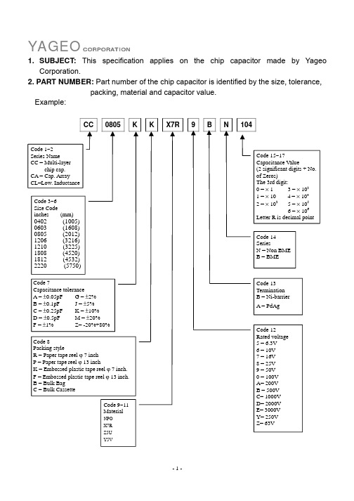
Code 9~11 Material
NPO X7R Z5U Y5V
Code 15~17
Capacitance Value
(2 significant digits + No.
of Zeros)
The 3rd digit:
0=×1
3 = × 103
1 = × 10 4 = × 104
2 = × 102 5 = × 105
CC1812 4.5±0.20 3.2±0.20 0.50 1.80 0.25 0.75 2.20
CC2220 5.7±0.20 5.0±0.20 0.50 1.80 0.25 0.75 2.20
Unit: mm
-3-
YAGEO CORPORATION
Aging Rate
∆C/C (%) 10
Aging Curve
国巨电容国巨贴片电容国巨电阻规格书国巨电阻规格书中文国巨电容型号国巨电子电容厂国巨电子
YAGEO CORPORATION
1. SUBJECT: This specification applies on the chip capacitor made by Yageo Corporation.
TDK 电感产品数据手册说明书

Dimensions: [mm]Scale - 4:1B CT e m p e r a t u r eT pT LCautions and Warnings:The following conditions apply to all goods within the product series of WE-PD of Würth Elektronik eiSos GmbH & Co. KG:General:•This electronic component is designed and manufactured for use in general electronic equipment.•Würth Elektronik must be asked for written approval (following the PPAP procedure) before incorporating the components into any equipment in fields such as military, aerospace, aviation, nuclear control, submarine, transportation (automotive control, train control, ship control), transportation signal, disaster prevention, medical, public information network etc. where higher safety and reliability are especially required and/or if there is the possibility of direct damage or human injury.•Electronic components that will be used in safety-critical or high-reliability applications, should be pre-evaluated by the customer. •The component is designed and manufactured to be used within the datasheet specified values. If the usage and operation conditions specified in the datasheet are not met, the wire insulation may be damaged or dissolved.•Do not drop or impact the components, the component may be damaged.•Würth Elektronik products are qualified according to international standards, which are listed in each product reliability report. Würth Elektronik does not warrant any customer qualified product characteristics beyond Würth Elektroniks’ specifications, for its validity and sustainability over time.•The responsibility for the applicability of the customer specific products and use in a particular customer design is always within the authority of the customer. All technical specifications for standard products also apply to customer specific products.Product specific:Soldering:•The solder profile must comply with the technical product specifications. All other profiles will void the warranty.•All other soldering methods are at the customers’ own risk.•Strong forces which may affect the coplanarity of the components’ electrical connection with the PCB (i.e. pins), can damage the part, resulting in avoid of the warranty.Cleaning and Washing:•Washing agents used during the production to clean the customer application might damage or change the characteristics of the wire insulation, marking or plating. Washing agents may have a negative effect on the long-term functionality of the product.•Using a brush during the cleaning process may break the wire due to its small diameter. Therefore, we do not recommend using a brush during the PCB cleaning process.Potting:•If the product is potted in the customer application, the potting material may shrink or expand during and after hardening. Shrinking could lead to an incomplete seal, allowing contaminants into the core. Expansion could damage the components. We recommend a manual inspection after potting to avoid these effects.Storage Conditions:• A storage of Würth Electronik products for longer than 12 months is not recommended. Within other effects, the terminals may suffer degradation, resulting in bad solderability. Therefore, all products shall be used within the period of 12 months based on the day of shipment.•Do not expose the components to direct sunlight.•The storage conditions in the original packaging are defined according to DIN EN 61760-2.•The storage conditions stated in the original packaging apply to the storage time and not to the transportation time of the components. Packaging:•The packaging specifications apply only to purchase orders comprising whole packaging units. If the ordered quantity exceeds or is lower than the specified packaging unit, packaging in accordance with the packaging specifications cannot be ensured. Handling:•Violation of the technical product specifications such as exceeding the nominal rated current will void the warranty.•Applying currents with audio-frequency signals may result in audible noise due to the magnetostrictive material properties.•The temperature rise of the component must be taken into consideration. The operating temperature is comprised of ambient temperature and temperature rise of the component.•Temperature rise is highly dependent on many factors including PCB land pattern, trace size, and proximity to other components.Therefore, temperature rise should be verified in application conditions.The operating temperature of the component shall not exceed the maximum temperature specified.These cautions and warnings comply with the state of the scientific and technical knowledge and are believed to be accurate and reliable.However, no responsibility is assumed for inaccuracies or incompleteness.Würth Elektronik eiSos GmbH & Co. KGEMC & Inductive SolutionsMax-Eyth-Str. 174638 WaldenburgGermanyCHECKED REVISION DATE (YYYY-MM-DD)GENERAL TOLERANCE PROJECTIONMETHODALa006.0002023-05-30DIN ISO 2768-1mDESCRIPTIONWE-PD SMT Shielded PowerInductor ORDER CODE74477830SIZE/TYPE BUSINESS UNIT STATUS PAGEImportant NotesThe following conditions apply to all goods within the product range of Würth Elektronik eiSos GmbH & Co. KG:1. General Customer ResponsibilitySome goods within the product range of Würth Elektronik eiSos GmbH & Co. KG contain statements regarding general suitability for certain application areas. These statements about suitability are based on our knowledge and experience of typical requirements concerning the areas, serve as general guidance and cannot be estimated as binding statements about the suitability for a customer application. The responsibility for the applicability and use in a particular customer design is always solely within the authority of the customer. Due to this fact it is up to the customer to evaluate, where appropriate to investigate and decide whether the device with the specific product characteristics described in the product specification is valid and suitable for the respective customer application or not.2. Customer Responsibility related to Specific, in particular Safety-Relevant ApplicationsIt has to be clearly pointed out that the possibility of a malfunction of electronic components or failure before the end of the usual lifetime cannot be completely eliminated in the current state of the art, even if the products are operated within the range of the specifications.In certain customer applications requiring a very high level of safety and especially in customer applications in which the malfunction or failure of an electronic component could endanger human life or health it must be ensured by most advanced technological aid of suitable design of the customer application that no injury or damage is caused to third parties in the event of malfunction or failure of an electronic component. Therefore, customer is cautioned to verify that data sheets are current before placing orders. The current data sheets can be downloaded at .3. Best Care and AttentionAny product-specific notes, cautions and warnings must be strictly observed. Any disregard will result in the loss of warranty.4. Customer Support for Product SpecificationsSome products within the product range may contain substances which are subject to restrictions in certain jurisdictions in order to serve specific technical requirements. Necessary information is available on request. In this case the field sales engineer or the internal sales person in charge should be contacted who will be happy to support in this matter.5. Product R&DDue to constant product improvement product specifications may change from time to time. As a standard reporting procedure of the Product Change Notification (PCN) according to the JEDEC-Standard inform about minor and major changes. In case of further queries regarding the PCN, the field sales engineer or the internal sales person in charge should be contacted. The basic responsibility of the customer as per Section 1 and 2 remains unaffected.6. Product Life CycleDue to technical progress and economical evaluation we also reserve the right to discontinue production and delivery of products. As a standard reporting procedure of the Product Termination Notification (PTN) according to the JEDEC-Standard we will inform at an early stage about inevitable product discontinuance. According to this we cannot guarantee that all products within our product range will always be available. Therefore it needs to be verified with the field sales engineer or the internal sales person in charge about the current product availability expectancy before or when the product for application design-in disposal is considered. The approach named above does not apply in the case of individual agreements deviating from the foregoing for customer-specific products.7. Property RightsAll the rights for contractual products produced by Würth Elektronik eiSos GmbH & Co. KG on the basis of ideas, development contracts as well as models or templates that are subject to copyright, patent or commercial protection supplied to the customer will remain with Würth Elektronik eiSos GmbH & Co. KG. Würth Elektronik eiSos GmbH & Co. KG does not warrant or represent that any license, either expressed or implied, is granted under any patent right, copyright, mask work right, or other intellectual property right relating to any combination, application, or process in which Würth Elektronik eiSos GmbH & Co. KG components or services are used.8. General Terms and ConditionsUnless otherwise agreed in individual contracts, all orders are subject to the current version of the “General Terms and Conditions of Würth Elektronik eiSos Group”, last version available at .Würth Elektronik eiSos GmbH & Co. KGEMC & Inductive SolutionsMax-Eyth-Str. 174638 WaldenburgGermanyCHECKED REVISION DATE (YYYY-MM-DD)GENERAL TOLERANCE PROJECTIONMETHODALa006.0002023-05-30DIN ISO 2768-1mDESCRIPTIONWE-PD SMT Shielded PowerInductor ORDER CODE74477830SIZE/TYPE BUSINESS UNIT STATUS PAGE。
- 1、下载文档前请自行甄别文档内容的完整性,平台不提供额外的编辑、内容补充、找答案等附加服务。
- 2、"仅部分预览"的文档,不可在线预览部分如存在完整性等问题,可反馈申请退款(可完整预览的文档不适用该条件!)。
- 3、如文档侵犯您的权益,请联系客服反馈,我们会尽快为您处理(人工客服工作时间:9:00-18:30)。
DFE201610E
Inductance Range: 0.24~10μH
(Unit: mm)
(Unit: mm)
∙ Miniature size: 2016 footprint (2.0mm×1.6mm) and low profile(1.0mm Max. height)
∙ The use of magnetic iron powder ensure capability for large current.
∙ The use of Flat wire for Low DC resistance. ∙ Magnetically shielded, low audible core noise. ∙ Reflow solderable.
∙ Operating temperature : -40~+125°C ∙ 小型薄型構造 (2.0x1.6mm角、高さ1.0mm Max.) ∙ 磁性材に鉄系磁性粉を用いた大電流対応 ∙ 平角線採用による低直流抵抗 ∙ 閉磁路構造、低コア鳴きノイズ ∙ リフロはんだ対応
∙
動作温度範囲:-40~+125°C
(1) Inductance is measured with a LCR meter 4284A (Agilent Technologies ) or equivalent. Test frequency at 1MHz
(2) DC resistance is measured with 34420A (Agilent Technologies) or 3541(HIOKI). (Reference ambient temperature 20°C)
(3) Inductance Decrease Current based upon 30% inductance reduction from the initial value
(4) Temperature Rise Current based upon 40°C temperature rise. (Reference ambient temperature 20°C)
(1) インダクタンスはLCR メータ4284A (Agilent Technologies ) または同等品により測定する。
測定周波数は1MHz 。
(2) 直流抵抗は測定器34420A (Agilent Technologies )または3541(HIOKI )と同等品により測定する。
(周囲温度20°C )
(3) 直流重畳許容電流:直流重畳電流を流した時インダクタンスの値が初期値より30%減少する直流電流値
(4) 温度上昇許容電流:コイルの温度が40°C 上昇する値 (周囲温度20°C を基準とする。
)
Recommended patterns
推奨パターン図
Metal Alloy Inductors
メタルアロイ®
インダクタ。