eCO系统用户手册1
ET 200eco PN M12-L 系统手册说明书

1
系统概述
2
安装
3
连接
4
组态
5
调试
6
维护
7
技术规范
8
安全相关关断
A
尺寸图
B
附件/备件
C
停用
D
08/2023
A5E48753351-AF
法律资讯
警告提示系统 为了您的人身安全以及避免财产损失,必须注意本手册中的提示。人身安全的提示用一个警告三角表示,仅与财产 损失有关的提示不带警告三角。警告提示根据危险等级由高到低如下表示。
约定
另请注意下列注意事项:
说明 说明中包含与以下内容有关的重要信息: • 文档中所述的产品 • 产品操作 • 文档中需要特别注意的内容,若不遵守这些内容,则可能会造成损坏。
前言
其它支持
• 有关技术支持的信息,请参见“Siemens 工业在线支持 (页 6)”部分。 • 有关各种 SIMATIC 产品和系统的技术文档信息,请访问 Internet
3.1
基本知识.......................................................................................................................... 21
3.2
无安装导轨的安装............................................................................................................. 22
文档使用范围
本文档适用于 SIMATIC ET 200eco PN M12‑L 分布式 I/O 设备。
AC500-eCo 使用手册

北京 ABB 电气传动系统有限公司 PLC 技术部
2
技术资料 AC500/Issue: 09.2011
1. 序言
1.1. 面向的读者
本手册面向的读者是那些负责调试和使用 AC500-eCo 的用户。读者需要具备基本的电气知识、电 气接线经验以及 PLC 操作方面的知识。
1.2.
准备工作
在开始之前,需要至少准备以下元件: 1. AC500-eCo 的 CPU(本手册以 PM564-T-ETH 为例)及 24V 直流电源; 2. RS485 的 USB 编程电缆(TK503)或以太网电缆; 3. PS501 安装 CD 及电脑; 4. 螺丝刀; 5. 电缆若干;
此外,带以太网的 AC500-eCo 与电脑连接还可以使用以太网电缆进行连接。
北京 ABB 电气传动系统有限公司 PLC 技术部
5
技术资料 AC500/Issue: 09.2011
2. 安装 PS501 Control Builder
如果你的电脑上的 CD - ROM 驱动器设置为“自动运行”,则安装界面自动打开。否则,你可以执行 位于 CD - ROM 根目录上的文件“CD_Menu_V5x.exe”,选择”开始”- >“运行”,然后输入 “[X]:\ CD_Menu_V5x.exe”(其中[X]是 CD- ROM 驱动器)来执行这个文件。
北京 ABB 电气传动系统有限公司 PLC 技术部
7
技术资料 AC500/Issue: 09.2011
北京 ABB 电气传动系统有限公司 PLC 技术部
4
技术资料 AC500/Issue: 09.2011
1.5.
PLC 与电脑连接
AC500-eCo 与电脑连接需要使用 TK503 编程电缆。如下图:
2021 ECO 5.0L 驱动系统安装说明说明书

Please visit for the most current instruction and warranty information.PLEASE READ ALL OF THE FOLLOWING INSTRUCTIONS CAREFULLY PRIOR TOINSTALLATION. IF AT ANY TIME YOU DO NOT UNDERSTAND THE INSTRUCTIONS, PLEASE CALL THE FORD PERFORMANCE TECHLINE AT 1-800-367-3788The use of a vehicle hoist is recommended for this installation. If you do not have access to one, use a hydraulic floor jack and jack stands to safely raise the vehicle.CAUTION: JACK STANDS MUST BE USED ON A LEVEL SURFACE AND BE SECURELY SEATED. FAILURE TO DO SO MAY RESULT IN PERSONAL INJURY OR VEHICLE DAMAGE 2021 ECO 5.0L Drivetrain Installation InstructionsSection Topic1.0 Introduction .…………………………………………………………………………………………………..2.0 Overview .……………………………………………………………………………………………………..3.0 Included/Possibly Required Components ..……………………………………………………………….1.0 IntroductionThis kit was developed by Ford Performance in order to allow performance enthusiasts the ability to install a 5.0L Gen3 Mustang Crate Engine (Fordequipment up to, and including, OBD I equipped vehicles. This Kit is NOT intended for fitment into OBD II equipped vehicles. Note: Cruise control is not available with this system.vehicle speed signal from CAN bus circuit. Analog gauges will require either a CAN translator box or a drive shaft speed3.7 Accelerator Pedal Position Sensor (APPS)•The Accelerator Pedal Assembly includes a pair of Integrated Pedal Position Sensors (APPS1/APPS2). This pedal has electrical properties designed specifically for correct interface with PCMengine operation.3.8 Evaporative System•The Purge Solenoid is required to control the flow of fuel vapors from the Carbon Canistor. It is required toEvaprotive Canistor ConnectionsEvaprotive Canistor Mounting Options3.9 Brake Aspirator•The Brake Aspirator utilizes a flow of air thru an orifice to increase the vacuum to the Brake Booster. The flow of air from the induction tube to the intake manifold is a specific calibrated volume that is accounted for in the engine contol software. The use of the Brake Aspirator is required for proper engine operation.3.10 Passive Anti-Theft System Module (PATS)The PATs module is matched to your Powertrain Control Module (PCM) as received. The PCM will not allow the starter to crank the engine without communications with the specific matched PATs module.The PATs module stores your hardware configuration for use by the PCM (tire circumference and axle ratio) Ford Performance Pro Cal Flash ToolA programing tool is included in the kit to configure your powertrain.Crank Position Sensor profile (also known as the misfire profile learning).3.14 Plastic Bag of Assorted Items3.15 Air Cleaner Assembly with Integral Mass Air Flow SensorThe AAT must be installed in the vehicle forward of the radiator or other heat exchangers.The installation location must be in the flow of fresh air to provide optimum performance as it effects the calculation of the delivered spark and fuel.3.17 Controls Pack Wiring Assembly•Connects to vehicle battery and inline connector on engine harness.•Contains Ford Performance Power Distribution Box (FPPDB) and High Power inline fuse.•Electrical connections to Accelerator Pedal (APPS) and Clutch Switch (CBT).•Wire leads for Ignition Switch & Starter.•Data Link Connector for reading Diagnostic Trouble Codes (DTCs).•Check Engine/Malfunction Indicator Lamp (MIL) for visual indication of engine control system fault code4.0 Pre-Installation of Harnesses and Drive Train4.1 Planning- Taking a few moments to plan your installation will make the installation and completion of the drivetrain much easier. To assist you, below are the external dimensions of the engine with the exhaust manifoldsinstalled.Total Width (without the AIS): 768mmTotal Length (without the exhaust or AIS) 1370mm:Total Length with AIS (without exhaust):1520mmMount the Floor Shifter and route the Shifter Cable.The Shifter Cable will need to be routed so the cable mounts to the Transmission with the cable end to thefront on the left side of the Transmission.Picture shown is for reference only to assist in component placement suggestionsThe following is a list of key factors to consider before any of the installation takes place:• PCM mounting location is limited by the length of the PCM lead of the Engine Harness (located on the rightfront corner of the Engine). The PCM Connector Lead measures 22 inches from the lower edge of the right Valve Cover. This will dictate the location of where the PCM will need to be mounted.• Ford Performance Power Distribution Box must be mounted, in the engine compartment, within 60 inches ofthe vehicle battery or positive battery post if you have a trunk mounted battery as dictated by the battery+/ ground lead lengths of the controls pack wiring harness.• Lay out the harness and components first in order to ensure that the wiring leads will reach everywhere youintend them to. This is a good check before you drill any holes or mount any components!• Plan on a good location to mount the EVAP Canister. Traditionally, they are located under the rear of theVehicle, close to the Fuel Tank.• If your transmission tunnel is very tight, decide how you will check your transmission fluid level after the firststart-up. You may need to fabricate an access hole to check it from above then, re-seal the hole with rubber body plug or a removable panel. If you test fit your drivetrain, that will be a good time to determine your needs.Fuse Box/PCM LocationAir BoxBattery BoxMAFFuel PressureRegulator5.1. Assembling the Drive Train- Remove the Engine (including all the components) from the packaging, and inspect the Engine for damage.Inspect the Crankshaft Sensor Ring for damage. If the Crankshaft Sensor Ring has beendropped, or has any visual damage, it must be discarded. A slight bend in any tooth of the ringcould result in a “no start” condition as this ring triggers the Crank Position Sensor (CPS).Place the Crankshaft Sensor Ring on the Crankshaft being sure the Locator Pin engages theHolding ToolIMPORTANT NOTEThe Ford 10R80 Automatic Transmission is a “sealed”, non-service unit. There is no Transmission Fluid Dip Stick Tube. Therefore, it is VERY important that you follow the Instructions below to initially fill the Transmission. You will need to check the fluid level AFTER the first start-up. Be sure you allow room in the vehicle to be able to execute the check.Install the Transmission Fluid Cooler Tubes and the new bolt to the Transmission on the forward left side of the Transmission.Torque: 18 lb/ft (25 Nm)Attach the Cooler Lines to the Bell Housing Stud.- Place a Exhaust Manifold Gasket on the Manifold Studs.- 1. Position the Catalytic Converter onto the Engine and finger-tight the nuts. - 2. Tighten the nuts in the sequence shown.- Install the Drive Train into the Vehicle.Install the Brake Aspirator.NOTE:It is very important that this Brake Aspirator is utilized as it increases the vacuum available to the Brake Booster as well as being important to the tuning in the PCM.To the EVAP CanisterIf not already present, install the Canister Purge Valve. The yellow colored hose on the right side of the above photo needs to be run to the EVAP Canister.Connect the Fuel Line from the Fuel Pressure Regulator.Connect your cooling system.BATTERYENGINESTARTER ALTERNATORSuggested Battery Cable diagramConnect the Battery positive to the Starter and Alternator.Ground the Engine to the Chassis.Pay close attention to the vehicle grounds. Many times, electrical Issues can be traced back to insufficient ground circuits. Ensuring your vehicle is well grounded now, will save you time and- Install and adjust the Shifter CableUnlock the adjuster.6.0 Control Pack Connection Details Item Connector #A -B -C C160AD C2040- -Inside the VehicleFigure 1b – Transmission Harness6.1 Engine Harness Routing(Automatic)Front View of Engine:6.3 Controls Pack Harness Installation InstructionsNOTE: To avoid electrical shock and/or damage to sensitive electrical control system components, before beginning any work, remove the vehicle’s negative Battery terminal and place a rag or towel between it and the Battery negative Post. The negative Battery terminal is not to be reinstalled until the last step of installation.1. Identify proper mounting location for the PCM, Power Distribution Box (Item A) & Inline Fuse Holder. Locate the PCMconnector (Item L) on the Engine Harness as indicated in Figures 2 and 3 by the “START HERE” arrow.- Shifter Lever Switch Pigtail.Pin 1 connect to Pin 4Pin 2 connect to Brake Switch Output (12v when the Brake Pedal is depressed)Pin 3 NOT USEDPin 4 connect to Pin 1Pin 5 Ground to ChassisPlug the Shifter in. Wiring the Shifter in this manner allows the Park Release to operate as intended in the 2020 Mustang. When the Brake Pedal is depressed, It will allow you to shift from Park. It will not operate when in any other Gear is selected.6.4 6-way I/P Pigtail Connection DetailsThe 6-way pigtail is to be connected according to the chart below. See also the diagrams on the following pages for illustrations of wire connection points, based on the ignition/starter switches that you intend to use. Setup A uses separate toggle switches for ignition and starter inputs, while Setup B uses an ignition cylinder with a key.WireColorGN Provides +12V to the fuel pump-Apply +12V to send a request to the PCM to energize the starterLight Blue6.4.5 Blunt Lead 5 – Ignition Relay Trigger (Light Green):Set-up A:Set-up B:7.0 Ford Performance Power Distribution Box Installation7.1. Before you start, yourecommended), one from Battery to fuse holder, the other one from fuse holder to FPPDB.7.2. Carefully remove the nut and washers on both terminals of the in-line fuse holder and set aside.7.3. Use one of your battery cables and place the eyelet onto one of the two in-line fuse holder terminals, then one of thewashers, and then tighten down with one of the two nuts.7.4. Locate the power terminal of the side of FPPDB, notice there is a battery positive blunt lead eyelet already attached8.0 Fuel SystemThe PCM is calibrated for a return style fuel system as shown below.- Included pressure regulator is set at the factory to 75psi. Do not try to adjust it.- Use only AN type fuel fitting to interface with OEM fuel rail.- Fuel Pump must be capable of 160 liters per hour flow at 75 psi..Fuel pump requirements: 160L/Hr minimum at 75psiA common and often overlooked problem is the location of the fuel pump or pumps. Optimally, the fuel pump should be mounted IN THE TANK to reduce the possibility of pump cavitation. Cavitation is essentially localized boiling caused by a reduction in pressure, generally occurring on the inlet side of a pump. This localized boiling results in fuel vapor bubbles which will reduce the volume of fuel the pump is capable of delivering to the engine. Any reduction in pressure or increase in temperature at the inlet side of the pump increases the chances that cavitation will occur. For this reason, it is always best to either have the pump inside the tank immersed in fuel or (in the case of an external pump) gravity fed, which will increase the pressure on the inlet side of the pump. If the fuel pump has to “pull” the fuel, this will result in a reduction in pressure at the fuel pump inlet potentially allowing cavitation and, thus, vapor bubbles to develop. These vapor bubbles are then drawn into the fuel pump and exit the high-pressure side of the fuel pump as compressed vapor. They travel the entire length of the fuel system and are expelled through the fuel injector. This can cause issues ranging from stumbles and hesitations to engine damage due to insufficient fuel delivery and lean A/F ratios. Sometimes this problem can characterize itself by only appearing when the weather gets warmer, which can confound the diagnosis of the issue. In certain cases, it may seem to only develop when driving on certain surfaces, because pavement reflects more heat than an off-road 4x4 trail. Remember, more heat and lower pressure on the inlet side of the pump means a greater chance of cavitation, which is to be avoided whenever possible.If you are using an external mounted fuel pump, you should run a very coarse (typically around 100 micron) filter on the inlet side of the fuel pump, and a finer (typically around 10 micron) filter on the outlet side of the pump. A paper filter is NOT recommended on the inlet of the fuel pump because it can cause a restriction in fuel flow which, as mentioned previously, can lead to cavitation.Warning: It is highly recommended that an inertia switch is incorporated into the fuel pump wiring to turn off the fuel pump in event of an accident.10.0 Wire Usage SchematicsThe following two pages detail the two most common wiring configurations—please choose one to complete installation of your controls pack kit. You will need to provide 12V HAAT wire yourself.11.0 Fuses & Relays•The following diagram outlines the array of fuses and relays included in the controls pack wiring harness, and the function of each.•NOTE: Do NOT replace any of the fuses with a higher value than those specified below.12.0 Troubleshooting tips:The following troubleshooting tips are intended for you to run a few quick tests to roughly determine what the issues are before calling or find a solution yourself:•Double check all the grounds. The wirings included in this kit is extremely sensitive to ground issues. Secure all the connections from the chassis grounds to the battery’s negative post. Do a continuity test with your multi meter between all your ground terminals and battery ground.•Check all reference voltages, confirm they are not shorted. Use a multimeter to measure the voltage at each sensor.It should read 5V.•If none of the sensors or components have power, check th ignition switch, ignition relay R6, and PCM relay R1 wiring. It should have 12V at both relay outputs with the ignition on. This is fused via F5 and F1 separately. Use a13.0 Connector Faces。
eHPoca 3in1 高效热泵系统用户手册说明书

eHPoca3in13in1 built-in The ultimate heat pumps.P. 2P. 1Heat pumpsP. 2P. 3Heat pumpsP. 4P. 575%25%Heat pumpsExternal heatWHA T IS A HEA T PUMP?A heat pump is used to heat and cool, as well as produce domestic hotwater. The way it works is similar to a fridge: the heat taken from a placewith a low temperature is transferred to a place with a higher temperature.So, the heat pump takes heat from a cold outside area and transfers toanother indoor, warmer area. By inverting the operating cycle, you can coolrooms in summer with the same principle: the heat extracted indoors istaken outdoors.This process uses the thermal energy already present in nature, so the heatpumps are highly efficient heat generators which use renewable, free energy.The heat pumps are powered by electric energy which allows a cooling cycleto be completed, but the production of heat occurs through absorption fromthe external source: the air, water or ground (geothermal heat pump).Electrical energy can also be supplied by a photovoltaic or wind plant. Inthis case, the thermal energy produced is completely free and renewable.Heat pump75% of the energyrequired is takenfrom outside.The remaining25% is electricenergy suppliedby the grid or bythe photovoltaicsystem.P. 6* daily energy requirement of one individual = 50 litres of hot water at 40° C** CO 2 emissions indirectly produced by national power grid 1kWhe = 0.4332 Kg CO 2ENERGY REQUIREDENERGY PRODUCED BY AGAS BOILERENERGY PRODUCED BY A HEA T PUMPCOMPARISON BETWEEN A GAS BOILER AND A HEA T PUMPP. 7dal 30% al 50%Heat pumpsEnergy savingsINNOVA DC Inverter heat pumps guarantee significant energy savings both in heating and in the production of domestic hot water thanks to the high levels of SCOP (seasonal coefficient of performance). Compared to a conventional heating system (e.g. boiler), the cost of energy, used for an entire winter, can be between 30% and 50% less.The requirement of a building is maximum at the design temperature and decreases linearly as the outside temperature increases.The heat pump with inverter compressor modulates the power supplied based on the building requirement.As the external temperature increases, the power supplied decreases and so, increases efficiency.The heat pump with on/off compressor always works at 100% and, as the external temperature increases, the power generated increases, in contrast to the building requirement. In these conditions, in order to meet the requested load, the compressor works by repeatedly turning off and on which significantly reduces efficiency.Efficiency of a Heat pumpInverter vs on/offheatersradiant panelsCOP : Represents the power produced and the power absorbedHeat pump Compressor On-OffDC Compressor InverterThermal loadExternal air temperature CO 2Inverter modulation areaThermal powerkWtP. 8InterfaceBUTLER web server is the system developed by INNOVA to manage an entire heating and cooling system directly in your home or remotely.BUTLER allows you to connect the heat pump, controlled mechanical ventilation system, fan coils and all the other system elements via a serial connection.BUTLER is complete, simple and intuitive at the same time. You can configure a weekly calendar with time zones, create specific zones and change the settings so your home is at the right comfort level for your needs.BUTLER,smart system controllocal PCDisplay Via network or WEBBUTLER with built-in displayVia WEBSmartphone or tabletRoom by room controlYou can control each room with BUTLER by configuring a weekly calendar with time zones, creating settings for each room or area, modifying the settings so your home is at just the right comfort level for your needs.BUTLER is both simple and intuitive: you can manage your own comfort both from the BUTLER display and from a computer or mobile device, such as a smartphone or tablet.Web Server BUTLERMain functions• Monitoring and control in local network or remotelyThe system can be managed by any smartphone,tablet or computer• Personalised winter and summer programmingYou can have different programmes for every season• Three temperature level setting on INNOV Afan coil networkFor each room or area, you can select 3 differentoperating temperatures, which can be modifiedat any time• Weekly programming scheduleY ou can set the schedule for the different functions foreach room; the same can be done for HRV and fan coils• PC-type network interfaceOnce the bus network has been set up between theheat pump and the fan coils, the connection to theweb server is the same as a standard computer• Remote assistanceWith the consent of the user, BUTLER can automaticallyenter the INNOV A cloud for diagnostics and assistanceif it is neededDomestic hot water settings Weekly schedulingHeat pumpsTotal controlRemote assistanceWith the consent of the user, BUTLER can automatically enter the INNOVA cloud fordiagnostics and assistance, if needed.Thanks to the internet connection, it ispossible to check if the INNOVA productsconnected to the BUTLER are workingcorrectly.Any malfunctions can be automaticallysent to the BUTLER at the support centrewhich can intervene by modifying theoperating parameters or deciding tointervene directly, thus providinga fast and prompt service.The advantage of choosing acomplete INNOVA system isthat we are your sole contactpoint for any requirement, bothfor programmed maintenanceand support. A complete,quality service.INNOVA HRA - iCONTROLLED MECHANICAL VENTILA TIONwith thermodynamic recoveryHeat pumps32kWH2OOUR HEA T PUMPSeHPoca3in1Internal hydraulic module connected to the external unit via refrigerant pipes. Flexible solution suitable for implementing tailor-made systems.Suitable for:Suitable for:Features:Features:Tower with integrated 200-litre DHW tank for and connected to the external unit via refrigerant pipes. Complete solution which guarantees reliability and space saving designPower up to 32 kWOfficesLarge homes Centralised systems Built-in water tank Medium-size homesApartmentsCompact sizeBuilt-in components Guaranteed resultH2OHeat pumps3in1 built-inRange of powerSuitable for:Features:Built-in cabinet with integrated 170-litreDHW tank and connected to the externalunit via refrigerant pipes.Ideal for apartments with outer wallinstallation.Medium-size homesApartmentsBuilt-in water tankBuilt-in componentsCompact sizeOutdoor installationMaximum heating power A7/W35Maximum cooling power A35/W7Power kW3534333231302928272625242322212019181716151413121110987654321Heat pumpseHPocaWidth505 mmDepth300 mmHeight900 mmInternal hydraulic module connected tothe external unit via refrigerant pipes.Ideal for:Indoor unit with compactsize. Only 30 cm deep.High range of poweravailable up to a maximumpower of 32 kW.Remote management viaWIFIMaximum A+++ energyclass(g. 9-12-15)• Offices, where DHW is not required.• Detached houses, thanks to thecombination of a DHW tank of a suitablesize capable of meeting high requirements.• Centralised multi-family systems thanksto the high range of power up to 32 kWper unit, possibility of installing additionalunits in sequence and availability ofstorage tanks for DHW that cansupply multiple utilities.1210987653411Heat pumpsAccessories kit (supplied installed in the unit)Accessories kit(supplied separately)eHPoca is a flexible solution.Suitable accessories are supplied based on the application.For large homes or apartment blocks, for example, the DHW requirement may be met by choosing the appropriate DHW tank capacity of between 200 and 1,500 litres.eHPoca is a heat pump which can be modular and used in sequence to meet high power requirements.The indoor unit must be installed indoors in a suitable room to house all the system components.A. Attic B. Laundry C. CellareHPoca installationOffices Large homes Centralised systemsExample of centralised system1. eHPoca indoor unit2. Domestic hot water tank3.Outdoor unit Refrigerant pipes Domestic hot water /heatingBasementGround floor1st floor2nd floorRoofHeat pumpsDomestic hot water Cold watereHPoca system diagramA. Outdoor unitB. eHPoca indoor unitC. 3-way valveD. Thermal storage tank for instant preparation of DHWE.Domestic hot water supplyF. Hydraulic separatorG. Secondary circuit pump H.Heating and cooling systemSETTING ROOM40°CHeat pumps3in1Tower with integrated 200-litre DHW tank andconnected to the external unit via refrigerant pipes.Ideal for houses and apartments for 4 peoplewith a standard consumption of DHW.The comprehensive range of options allows theoverall size of the system inside the indoor unitto be maintained, so that a technical room is notrequired.All the hydrauliccomponents are integratedin the indoor unit.DHW production up to 40°C of external air.Remote management viaWIFIMaximum A+++energy class(g. 9-12-15)Width600 mmDepth600 mmHeight2000 mm3in1 diagramA. BoilerB. Domestic hot waterutilitiesC. High temperature utilities(decorative radiators) D. System utilities1. Outdoor unit2. Plate exchanger3. Automatic vent valve4. System safety valve 3 bar5. System expansion vessel24 litres6. Filling unit7. Y filter 8. System pressure gauge9. Electrical heaters 2-4-6 kW(optional)10. Primary pump circuit11. ACS/system 3-way valve12. Domestic hot water tank200 litres13. Boiler vent valve14. Stainless steel coil forinstant DHW heating15. DHW safety valve 7 bar16. DHW thermostatic mixer17. Hydraulic separator(optional)18. Secondary circuit pump(optional)19. Inertial tank 20 litres(optional)20. Heated towel rail pump(optional)21. Solar load valve (optional)22. Solar safety valve 3 bar(optional)23. Solar circuit pressuregauge (optional)24. Solar circuit pump(optional)25. Solar heating coil(optional)26. Solar expansion vessel24 litres (optional)27. Solar panelHeat pumpsBACGFKDEHIJ3in1 standard componentsWater and cooling connectionsStandard componentsA. 3in1 structure and cover panels with RAL9003 finishB. Automatic vent valveC. System safety valve 3 barD. System expansion vessel 24 litresE. System filling unit and Y filterF. Pressure gaugeG. Primary circuit circulation pump H. ACS system 3-way valveI. Domestic hot water tank 200 litres J. DHW safety valve 7 bar K.DHW thermostatic mixerL MN O PQR AHeat pumps3in1 accessories kitsupplied installedin the unitAccessories kit suppliedinstalled in the unitL. BUTLER + Tablet: control system and remote managementvia internet/WIFIM. Separator kit with secondary pump for 5-7 kW unitN. Separator kit with secondary pump for 5-15 kW unitO. Heated towel rail kitP. Electrical heater kit 2-4-6 kW for system and ACSQ. Solar kit (can be used if there is no inertial tank kit):control unit, pump, safety valve, expansion vessel24 litres, filling unit, system filling valveR. Inertial tank kit 20 litres2The 3in1 is a complete solution.All the system elements are contained inside the cabinet to save space and provide greater reliability because everything is installed, adjusted and tested in the factory.The indoor unit can be installed indoors in any room thanks to its compact size and elegant design.A. Kitchen / Living room B. Laundry / Cellar3in1 installation instructionsMedium-size homesApartmentsExample of system1. 3in1 indoor unit2.Outdoor unit RefrigerantDomestic hot water / heatingGround floor1st floorHeat pumpsDomestic hot water Cold water3in1 system diagramA. Outdoor unitB. 3in1 indoor unitC. Domestic hot water supplyD. Heating systemSETTINGHeat pumps3in1 built-inIndoor unit consisting of a cabinet to buildinto the internal or perimeter wall withaccess from the outside, such as a balconyor connected to the outdoor unit viarefrigerant pipes.Ideal for apartments with 3-4 people witha proportionate consumption of DHW,thanks to the 170 litre storage tank.Modular indoor unit with various optionsto fulfil all the system requirements of anapartment.High range of poweravailable up to a maximumpower of 23 kW.Modularity, thanks to awide variety of optionalmodules to fulfil allsystem configurationsWidth950 mmDepth350 mmHeight2200 mmRemote management viaWIFIMaximum A+++energy class(g. 9-12-15)BAHeat pumps3in1 built-in diagramA. Domestic hot water utilitiesB.Utilities1. Outdoor unit2. Plate exchanger3. Automatic vent valve4. System safety valve 3 bar5. System expansion vessel 24 litres6. Filling unit7. Y filter8.System pressure gauge9. Electrical heaters 2-4-6 kW (optional)10. Primary pump circuit 11. ACS/system 3-way valve 12. Domestic hot water tank 170 litres13. Boiler vent valve14. Stainless steel coil for instant DHW heating 15. DHW safety valve 7 bar 16. DHW thermostatic mixer 17.Inertial storage tank / 30 litre hydraulic separator (optional)18. Secondary circuit pump (optional)19. Secondary circuit pump and mixer valve (optional)20. Solar load valve (optional) 21. Solar safety valve 3 bar (optional)22. Solar circuit pressure gauge (optional)23. Solar circuit pump (optional) 24. Solar heating coil (optional) 25. Solar expansion vessel 8 litres (optional) 26. Solar panelCDE GIKFLHB AJA. Built-in kit with front closure doorsB. Domestic hot water tank 170 litresC. Hydronic moduleD. Automatic vent valveE. Differential pressure switchF. Primary circuit circulation pumpG. Safety valve 3 barH. Expansion vessel 24 litres I. DHW thermostatic mixerJ. System filling unit and Y filter K. ACS system 3-way valve L.DHW safety valve 7 barStandard 3in1 built-in componentsStandard componentsSOQPRNMTUAHeat pumpsM. Inertial storage tank 30 litresN. Hydraulic separator kit 30 litres and secondary circuit pumps kit control board O. Secondary circuit pump kit for 5-7 kW unitsP. Secondary circuit pump kit+mixing valve for 5-7 kW units Q. Secondary circuit pump kit for 5-15 kW unitsR. Secondary circuit pump kit+mixing valve for 5-15 kW unitsS. Solar kit: control panel, pump, safety valve, expansion vessel 8 litres, filling unit T. Electrical heater kit 2-4-6 kW for system and ACSU.BUTLER + Tablet: control system and remote management via internet/WIFI3in1 built-in accessories kitAccessories kit1.Positioning of the built-in casing in the wall.The 3in1 built-in is a flexible solution with various modules which can also be installed at a later stage depending on the system configuration.The unit housing is inserted in the wall during the building work. There are hydraulic connections in the housing for connection to the water supply.The various internal modules are installed afterwards when the system has been completed. A. Landing access to apartment B. LaundryC. Terrace / Balcony3in1 built-in installationMedium-size homesApartments3in1 built-in installation stages2.Connection of the systemconnections from three different positions: rear, side or bottom.3.Installing the internalcomponents and relevant connections.2Heat pumpsDomestic hot water Cold waterA. Outdoor unitB. 3in1 built-in indoor unitC. Domestic hot water supplyD. Heating systemENVIRONMENTSystem diagram of 3in1 built-inExample of system1. Heat pump (3in1 built-in)2.Outdoor unit RefrigerantDomestic hot water / heatingOutdoor unitsWidth 799 mm Weight 39 Kg Weight 69 KgWeight 98 Kg (25T - 128 kg)Width 940 mm Width 940 mmDepth 299 mm Depth 340 mm Depth 340 mmHeight 619 mm Height 996 mm Height 1416 mm (25T - 1526 mm)Single fan unit5M - 7MSingle fan unit9MTwin fan unit12M-12T-15M-15T-18T-25THeat pumpsDistance between components.AdvantagesSilent unit thanks to the continuous modulation of the fan with DC inverter motor.DC inverter compressor with wide modulation range.Advanced algorithms for preventing frosting offinned coil.Finned coil with hydrophilic coating and subcoolingcircuit.45-15520External air temperature C°External air temperature °CSystem water temperature °CSystem water temperature °CHeating be means of electrical heaters, boiler or solar integration Integration by electrical heaters or boilersHeating and domestic hot waterCoolingInstallation distances≥ 15 cm≥ 20 cm≥ 25 cm≥ 20 cm≥ 50 cm≥ 50 cm≥ 50 cmHeat pumpsTechnical data sheets1. Water out T 35°C / ext. air T 7°C / R.H. 85%2. Water out T 35°C / ext. air T -7°C3. Water out T 18°C / ext. air T 35°C4. Water out T 7°C / ext. air T 35°C5. Seasonal efficiency and BT Energy Class Efficiency certified according to UNI EN 14825 by third party accredited according to standard UNI EN 17025 Rating performance according to UNI EN 14511The performance specifications indicated may undergo variationsHeat pumpsT ABLE OF HEA T PUMP PERFORMANCE FOR HEA TING - RA TING FREQUENCYT. ae =T. a =DC=PF =PA =Heat pumpsT ABLE OF COOLING PERFORMANCE - RA TING FREQUENCIESOutdoor ambient temperature (C°)Output water temperature (°C)Heating power (kW)Cooling power (kW)Total power absorbed (kW)The performance specifications indicated may undergo variations without prior noticeThe performance specifications, in accordance with the test conditions, take all the auxiliary elements and defrosting cycles into accountT ABLE OF HEA T PUMP PERFORMANCE FOR HEA TING - MAXIMUM FREQUENCIESP. 39T. ae =T. a =DC =PF =PA =Heat pumpsT ABLE OF COOLING PERFORMANCE - MAXIMUM FREQUENCIESOutdoor ambient temperature (C°)Output water temperature (°C)Heating power (kW)Cooling power (kW)Total power absorbed (kW)The performance specifications indicated may undergo variations without prior noticeThe performance specifications, in accordance with the test conditions, take all the auxiliary elements and defrosting cycles into accountP. 40Available pressure curvesPRIMARY PUMP CIRCUIT eHPoca PRIMARY PUMP CIRCUIT 3in1 and 3in1 built-inSEPARA TOR KIT with secondary circuit pump for 3in1 (optional)SEPARA TOR KIT with secondary circuit pump for 3in1 built-in (optional)Separator kit with secondary circuit pump for 5-7 kW unitSeparator kit plus secondary circuit pump for 5-15 kW unitDp (kPa): residual available pressure to unit fittings Q (m3/h): water flow rateP. 41Heat pumpsP. 42P. 43Heat pumpsP. 44CREDITSProduct DesignerLuca PapiniArt Direction & GraphicFederico CastelliPhotographyOttavio TomasiniSpecial thanks to:Akira NishikawaNext Village, 50 apartmentsIndependent systems with 3in1 heat pumps Viterbo, ItalyDetached house withtimber frameSystem with eHPocaheat pump Ledro, ItalyP. 45We turn ideasinto reality.INNOVA s.r.l.Via 1° Maggio, 838089 Storo (Tn)Tel. +39 0465 670104 Fax: +39 0465 674965********************** Edizione 2019/1。
ECO新风线控器说明书

1主界面图1.主界面控制主界面主要有7个按键,分别是开关按键(),模式按键(),风速调节按键(),确定按键(),定时按键(),上键(),下键()。
液晶显示器上显示出风口温度、设定温度、时钟、工作模式、风扇开关状态、风速,报警状态等信息。
温度以摄氏度表示当前时间为24小时制(时:分)。
如果当前有报警,会有报警图标“”闪烁;无报警则不显示。
左下角4个8有报警时会滚动显示当前机组和报警总数,滚动时间间隔为5秒,5秒后显示下一个机组号码和它的错误总数,无故障的机组不显示,最多可显示8个机组。
长按上键()进入报警查看。
2系统图标自动模式。
制冷模式。
制热模式。
送风模式。
当前显示温度值当前显示湿度值室外风机开启,如果是调速的室外风机可以根据后面的显示是高速还是低速。
时间设定模式远程开关机当前有报警线控器与主板通讯故障按键操作说明:长按:按住按键3秒以上有效短按:按住按键3秒以下有效1.主页面下短按定时按键()进入定时时间查询页面2.主页面下长按定时按键()进入时间设定页面3.主页面下长按上键()进入故障查询页面4.不在主页面下长按确定按键()返回到主页面5.主页面下短按风速调节按键()在高速低速之间切换风速6.故障查询和设定时间页面下短按风速调节按键()返回上一层菜单7.主界面下短按模式按键()用于切换当前工作模式。
8.主界面下短按开关按键()系统开关机切换。
9.主界面和定时时间查询页面下短按上键下键,用于修改设定的控制温度。
10.故障查询页面下短按上键下键,用于选择要查看的机组号和故障代码。
11.时间设定页面下短按上键下键,用于修改时间。
3主界面主界面下会显示出风口温度(左侧)和设定温度(右侧)。
可以利用上下键直接修改设定水温,温度值可设定的范围:16℃~30℃。
右下角数字显示系统实时时钟,左下角数字显示故障机组号及对应故障的个数,多个机组故障时,可以循环显示。
当机组无故障时,不显示。
4故障查询页面主界面下长按上键()进入故障查询页面。
ECO作业流程说明
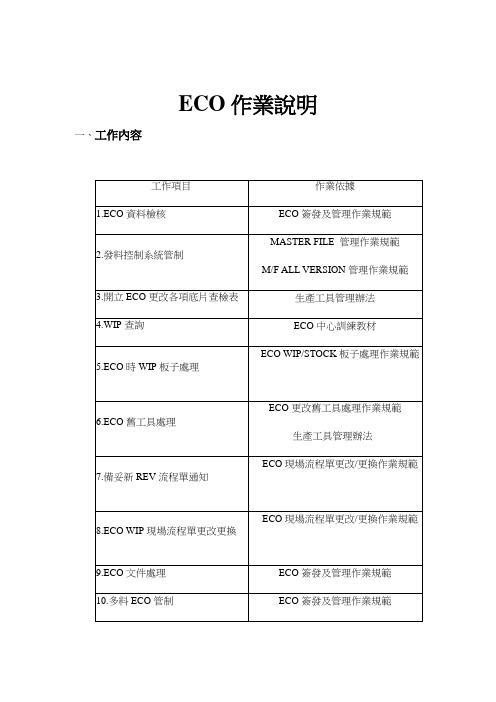
ECO作業說明一、工作內容ECO簽發及管理作業規範MASTER FILE 管理作業規範M/F ALL VERSION管理作業規範生產工具管理辦法ECO中心訓練教材ECO WIP/STOCK板子處理作業規範ECO更改舊工具處理作業規範生產工具管理辦法ECO現場流程單更改/更換作業規範ECO現場流程單更改/更換作業規範ECO簽發及管理作業規範ECO簽發及管理作業規範ECO簽發及管理作業規範內層銅渣偵測板資料變更提示單作業規範O/S FIXTURE SAMPLE及ECO處理作業規範流程單檢驗作業規範CM轉CC生產P/N各項PCB工具檢驗作業規範一次銅電流作業規範二次銅電流作業規範二、ECO處理作業總流程三、作業步驟3-1 執行ECO文件處理作業☞ ECO會簽傳送至ECO中心(ECO簽發流程如附件一、↓ECO A式如附件1)☞依ECO料號、舊版序找出對應的工程圖(工程圖袋如↓附件2)☞舊工具作廢直接將原稿流程單扯下作為更改藍本,若↓共存則COPY一份原稿流程單作為更改藍本☞填寫ECO更改目的、更改內容是否明確、清楚,KEY↓PROCESS能否判定,若含糊不夠明確,應向簽發人詢問澄清☞數量是否準確,資料是否齊全↓☞工具是作廢,還是共存,是否都很清楚、明了↓☞ WIP板子按何種方式生產或按何種方式處理↓是否填寫清楚、明了☞料號版序書寫是否正確,版序進階是否正確;有多個↓版序共存時,應列出讓CSE/SALES確認舊版序工具處理方式(依據附件4檢查)☞交于主管核准↓☞舊版序作廢應立即鎖“10”,版序未前進但流程單內↓容有改應鎖“55”(依據附件5作業, 依據附件6操作)☞若ECO A式未編號,須交藍圖室編ECO .NO.↓☞詳細操作見附件7↓☞填寫清楚查檢表各項目,送與照相房簽收,第一聯留↓存(底片查檢表見附件8)☞依照A式KEY PROCESS及流程單、WIP帳填寫↓(ECO B式見附件9)☞ ECO料號、新版序(ECO C式見附件10)↓☞填寫工具處理及WIP板子處理傳票及通知單,若工具↓共存,則不需此步(傳票見附件11~17)☞登錄ECO出件日期及內容(表格見附件18)↓☞填寫ECO日期、ECO號碼、更改內容等↓☞ COPY附件留存其余給藍圖室分發,ECO資料傳與CAM及照相房,注意有附件時應提示藍圖室分發給品管及藍圖室,有工程圖時還要分發給成型課3-2 ECO舊工具處理作業☞依據A式定義舊生產工具作廢而非共存↓☞以電腦系統查出現場應有底片套數,操作見附件19↓☞依A式及KEY PROCESS判定工具立即收回作廢,在舊生產工具收回傳票上填寫清楚ECO號碼、ECO料號、收回工具之版序、各工具使用↓生產單位現有工具類別及數量及處理日期、限定收回日期并注明立即收回填寫WIP完成收回傳票☞依A式及KEY PROCESS判定工具WIP完成收回作廢,在舊生產工具收回傳票上填寫清楚ECO號碼、ECO料號、收回工具之版序、各工具↓使用生產單位現有工具類別及數量及處理日期并注明WIP完成收回,處理時限需在WIP過站后票發出時填寫報表登錄☞把WIP立即收回傳票填寫之所有工具登錄在“ECO 舊工具WIP立即收回報廢FOLLOW-UPLIST”上(表格見附件20)↓把WIP完成后收回傳票填寫之所有工具登錄在“ECO 舊工具WIP完成后收回報廢FOLLOW-UPLIST”上(表格見附件21)發送傳票☞把工具立即收回傳票立即送與工具使用相應單位簽收,并在送傳票傳票處簽名,第一聯留存,↓其余3聯留與現場單位;WIP完成收回需建檔管理,定期查看WIP是否已過站,過站立即發出傳票收回舊工具(同立即收回)測試模具資料提供☞依據內層銅渣偵測板資料變更提示單作業規範,并依↓據CM廠提供之資料,自行填寫完成(表單見附件22)提供O/S模具查檢表☞依據O/S FIXTURE SAMPLE及ECO處理作業規範↓并依據CM廠提供之資料,自行填寫完(表單見附件23)FOLLOW-UP ☞跟催工具處理執行狀況(舊工具收回、新工具提供)↓工具收回正確☞執行傳票送回時,檢核工具是否真正準確收回,若工具未准時處理,反應與主管并知會相關↓單位主管,提出改善對策;收回正確登錄報表新工具已提供☞ ECO C式傳回,已填寫完成↓3-3 ECO WIP/STOCK 板子REWORK 處理作業☞依據ECO A式定義板子REWORK↓☞ REWORK通知單由簽發人填寫、并附在ECO A ↓式后(REWORK通知單見附件24)☞檢核REWORK通知單內容清楚是否與A式相↓符,并簽收REWORK通知單☞依據ECO REWORK 通知單內容登錄于ECO ↓WIP/STOCK板子REWORK/報廢管理報表(報表見附件25)☞把通知單送與REWORK執行單位、CQE、生↓管簽收,第一聯留存☞每周送報表與生管填寫執行情況及完成日期↓☞通知單及報表整理存檔管理3-4 ECO WIP/STOCK 板子報廢處理作業☞依據ECO A式定義WIP報廢之板子↓☞依ECO A式填寫傳票內容↓☞登錄ECO WIP/STOCK板子REWORK/報廢管理↓報表(報表見附件26)☞把傳票送與報廢執行單位簽收,第一聯留存↓☞裝訂處理傳票管理↓☞一周送與生管填寫完成日期及執行情況↓☞報表存檔管理3-5流程單更改、更換操作☞依ECO A式及WIP狀況已判斷須更改、更換流↓程單☞操作見“附件27 ”,依批號列印一份電腦帳單↓☞在電腦帳單上標示出須調帳的批號↓☞將ECO更改後原稿流程單COPY一份作為↓更改藍本☞標示流程單須更改的內容及途程站別↓☞在M/F上蓋“流程單更改”章并填寫↓EC.NO及操作方式☞需注明調帳之內容及列印現場流程單之批數↓(樣本見附件28)☞生管調電腦帳并依批數列印現場更改流程單,↓并交回ECO中心ECO中心流程單更改更換☞赴現場更改、更換現場流程單↓附件填寫并登錄報表☞在ECO WIP流程單更改、更換FOLLOW- ↓UP LIST報表上登錄(報表見附件29)登錄報表并交于生管確認☞將ECO WIP流程單更改、更換FOLLOW-UP LIST報表定時交于生管確認3-6報表及傳票填寫1 ECO B式之填寫操作“立即收回工具”欄填寫立即收回作廢工具的版序“WIP完成收回”欄填寫WIP完成后收回作廢的生產工具的版序“工具共存”欄填寫工具之版序“P/N-REV”欄填寫處理之料號及版序依列印之WIP電腦帳填寫站別、數量標示各站別WIP/STOCK板子的處理方式及流程單處理方式填寫ECO.NO. 及處理日期2制前工程課ECO進/出登錄表之填寫填寫操作步驟ECO 日期☞此欄填寫ECO出件日期↓☞此欄填寫ECO號碼即ECO A式內ECO NO之↓數據☞此欄填寫ECO料號↓☞此欄填寫ECO舊版序↓☞此欄填寫ECO新版序↓☞此欄填寫是否有黃單子ECO↓☞此欄依ECO A式填寫(C=客戶,S=業務,Q= ↓品管,E=工程)☞此欄依ECO A式填寫(A=重新制作,B=局部↓更改,C=簡易更改)☞此欄依ECO A填寫(O=立即作廢,S=局部作↓廢,T=WIP完成后作廢,C=共存)☞此欄填寫ECO A 式訂單交期之日期↓更改順序☞此欄依ECO A式填寫工具更改之優先順序↓ECO OUT ☞此填寫ECO A 式上之出件時間↓ECO 內容摘要☞此欄填寫ECO更改內容之記錄↓工具別☞此欄依ECO B式分別填寫各工具的處理方式(R=立即作廢,F=WIP完成后作廢,C=共存)注意﹕每頁需填起止日期便于查詢其余報表可參照此種方式填寫3-7 流程單CHECK LIST需建立原稿流程單☞新料號、ECO版序前進或ECO時流程單內容有更改↓列印流程單☞列印需建立(更新)之流程單,操作見附件30 ↓交叉核對☞與CM傳來之流程單交叉核對,原則上兩張流程單應↓當一致,否則應檢查其出入之原因或詢問CM設計者☞依照流程單check list逐項檢查(流程單check list 見附↓件31)并填寫完整,如發現疑問,詢問CM設計者,得以解決☞將原稿流程單依料號類別、順序裝訂在相應的“原稿↓流程單資料夾”☞將DEC發料控制代碼改為“CC”ECO作業注意事項﹕1.在接到ECO后,KEY PROCESS或需更改之工具自己不能確定時,必須詢問ECO簽發人,準確判定。
(经济型)ECOTRON使用说明书
第4页
E20185-P920-B700-X-7400中文版
3 一般的描述
继电器输出
用于开关D量C输2出4V信s号up的ply外部24 V直流电源for(oPut2p4utesx(t.P)24 ext.)
5个开关量5输bi出nary outputs
M 地(外部gr地ou)nd (M ext.) 实际位置po信si号tion4—0/420…mA20 mA (只有调节型才有)
保留所有权利!
订货号: E20185-P920-B700-X-7400中文版
内容
页
1 总的说明
3
1.1 和安全有关的术语
3
1.2 一般的安全准则
3
2 运输和储存
4
3 一般的描述
5
4 安装和联接
6
4.1 安装在阀门上
6
4.1.1 A 型输出轴
6
4.1.2 螺杆保护管
6
4.2 电气联接
7
4.3 分体安装
停止 开
STOP OPEN
关 CLOSE
M 地(外g部ro地un)d (M ext.)
c通ha道nn1el 1 c通ha道nn2el 2 output DDCC2244VV(P电2源4 输int出.) 给in电pu子t D板C供2电4V的supply 外fo部r eDleCct2ro4nVi电cs源unit (P24)
如果使用了其它类似的防腐的螺栓,则螺栓表面要涂上少许的凡士林。 旋进深度不少于 1.25 x 螺栓直径。 注:8.8级意味者抗拉强度不小于800N/mm2,屈服点为 80%=600N/mm2。
• 均匀的以对角线的先后顺序拧紧螺栓。
4.1.1 A型输出轴
ECO 系列自动门使用说明书
ECO Series AUTOMATIC DOOR SYSTEM1、Using permanent magnet DC motor drives, more stable performance, and high precision .2、Smooth operation even with high speeds.3、Pre-adjusted and tested in the factory with self-learning functions for opening and closing speed.No extra works for additional adjustments in the jobsite make theinstallation works fast and easy.saving space and flexible installation.4、Lower energy consumption.TYPE: ECO 02/C 中分轿门TYPE: ECO 02/CTwo Panels Center Opening Car DoorTYPE: ECO 02/R-L旁开轿门TYPE: ECO 02/R-LTwo Panels Telescopic Opening Car DoorOSCAR O SeriesAUTOMATIC DOOR SYSTEM1、Using AC VVVF motor drive, controlled by Panasonic VVVFdoor inverter.2、It utilizes the synchronous belt drive, low noise.3、Strong resistance of electromagnetic interference.4、Speed, position and torque adjustable for opening andclosing curve.5、Towed truck with mechanical anti-derailment devices.TYPE: OSCAR 02/CPL 60065070075080085090095010001050110011501200D162/D2217/D3/225A 1290134013901560166017101890194019902190224022902340B211271296361436中分轿门TYPE: OSCAR 02/CTwo Panels Center Opening Car DoorOSCAR 系列自动门AUTOMATIC DOOR SYSTEM标准配置不含轿门锁 Standard configuration are not including the car door lock.接受特殊规则定制 Accept for special size Customized.ECO 中分门机OSCAR中分门机中分层门TYPE: 01/CTwo Panels Center Opening Landing DoorECO/OSCAR 系列自动门AUTOMATIC DOOR SYSTEMTYPE: 01/C• TYPE:01/C 层门同时适用ECO、OSCAR 系列门机。
ECO基础设置和应用操作手册_20121009
Oracle EBS 工程变更系统基础设置和应用文档作者: 柳茂创建日期: 2012-10-19更新日期: 2012-11-11Version: 1.0文档控制更改记录审阅分发人员目录1ECO模块基础设置 (1)1.1设置ECO相关的配置文件 (1)1.2定义优先级 (2)1.3定义ECO更改类型 (2)1.4定义审批列表 (3)1.5定义原因 (4)1.6定义自动编号 (4)2ECO部门和ECO安全性控制 (5)2.1物料清单访问控制 (5)2.2ECO部门权限管理 (6)3物料版本与ECO的关系 (8)4ECO各种审批流程详解 (11)4.1标准审批流程 (11)4.2表单审批流程 (12)4.3ERES审批流程 (12)5ECO的实施对后续业务的影响 (13)5.1ECO实施对工单的影响 (13)6ECO在工程管理模块中的应用 (15)6.1工程环境和制造环境隔离 (15)6.2工程环境转制造环境 (16)7其他关于ECO有趣的功能点 (17)7.1ECO能够分行实施 (17)7.2ECO能够更改并且仅仅更改BOM行上的说明性弹性域 (17)7.3ECO可以更改已经失效的物料 (19)1ECO模块基础设置1.1设置ECO相关的配置文件路径:系统管理员——配置文件——系统和ECO相关的配置文件:1.2定义优先级路径:ENG——设置——优先级定义ECO的优先级,用于标识不同的ECO的优先程度和紧急程度。
1.3定义ECO更改类型路径:ENG——设置——更改类型设置ECO的更改类型。
ECO的更改类型可以和优先级、审批流程关联,从而精确控制各种类型的ECO在不同的优先级下采用哪种审批流程。
并且可以控制哪种ECO类型可以修订工程物料。
ECO类型与流程关联:关于ECO流程设置参考后文:ECO各种流程审批详解。
1.4定义审批列表路径:ENG——设置——审批列表定义一个审批列表,在审批列表中加入员工。
1.5定义原因路径:ENG——设置——原因定义ECO修订物料的原因。
ECO-DKL-1说明书
一、概述:ECO-DKL-1-W型电控柜是DZL2-1.25-AⅡ链条炉排卧式快装锅炉配套,用于控制锅炉的引风机、鼓风机、水泵电机、炉排电机、出渣电机、给煤电机及水位显示、报警、危低水位停炉保护,保证锅炉安全运行的关键设备。
本电控柜为立式结构,重量轻,体积小,操作板置于上半部,因而操作按钮不易落灰,从而可延长元件的使用寿命。
二、型号及意义:DKL-1CECO:经济型D:电气K:控制柜L:链条传动2:锅炉的蒸发量三、电控柜的主要功能:1、引风机、鼓风电机、出渣电机、水泵电机、炉排电源均接成直接启动和停止。
2、水泵电机的启动,停止备有手动-自动功能。
其转换装置由钮子开关1SA来完成。
处于手动位置时,按一下2SB即可启动,按1SB即可停止抽水,处于自动位置时,由水位继电器控制水泵电机的启动和停止。
3、锅炉水位控制系统由三个水位继电器组成,其中,由其中两个控制超高水位、极低水位的声光(蜂鸣器、面板指示灯,其中高报警为绿色,低报警为红色)报警及联锁停炉控制功能;由另外一个水位继电器控制水泵的低液位自动启动、高液位自动停止、高低水位灯光,声音报警自控系统。
水位在危低水位时,引风、鼓风、炉排均不能正常工作,只有水泵电机工作,高于危低水位后,引风、鼓风、炉排控制回路方能在人工启动后进行工作。
4、电控柜设有调试/运行选择开关2SA,当开关处于调试位置时,锅炉的各电机可单独启、停,便于对锅炉进行调试和维修,当开关处于运行位置,可对引风、鼓风机的启动和停止进行联锁控制,并可以在锅炉水位处于危低状态下,自动停止引风机、鼓风机和炉排电机。
不管该装置处于何种状态,均有高低水位及超压的声光报警。
当处于运行位置时还动作危低水位停炉的保护功能。
按一下3SB按钮即可解除声音报警。
报警灯显示必须在锅筒水位恢复正常后方可自动解除。
5、炉排转动由炉排控制器控制,请详细阅读其说明书。
四、技术参数:1、电源进线:3相四线制∽380伏±5% 50HZ2、控制电源:AC220伏±10% 50HZ3、功率:≤30KW4、工作条件:0-50℃相对湿度≤85% 无振动和腐蚀气体5、重量:150Kg6、水位控制范围:正常水位:±30mm高水位报警:+60mm保护停炉水位:-60mm五、包装运输及保管:1、包装前保证:无积尘,出厂技术资料、合格证齐全。
- 1、下载文档前请自行甄别文档内容的完整性,平台不提供额外的编辑、内容补充、找答案等附加服务。
- 2、"仅部分预览"的文档,不可在线预览部分如存在完整性等问题,可反馈申请退款(可完整预览的文档不适用该条件!)。
- 3、如文档侵犯您的权益,请联系客服反馈,我们会尽快为您处理(人工客服工作时间:9:00-18:30)。
eCO系统用户手册目录1 eCO系统安装及配置 (2)1.1 系统概述及配置 (2)1.2 软件安装 (2)1.3 eCO系统部署方案 (3)1.4 样品图片准备与图片加密 (5)1.5 登录系统 (6)2 系统管理 (11)2.1 基础档案下载 (12)2.2 系统参数设置 (12)2.3 数据库设置 (15)2.4 用户设置 (15)2.5 扩展列头自定义 (17)2.6 数据分发 (18)2.7 数据收集 (20)3 订货操作 (20)3.1 订货会下单 (20)4 报表查询 (29)4.1 订货数据分析 (29)4.2 订货现场分析 (30)2 百胜eCO订货会管理软件1 eCO系统安装及配置1.1 系统概述及配置eCO系统可以将数据分发到下面客户,客户使用eCO系统进行下单,下单后总部将数据收集到iOM系统中,再通过iOM系统将订单上传到对应的总部数据库中,用分摊工作量的方式来大大减小订货会对总部的压力。
环境配置:WINDOWS98/2000/XP/2003/vista系统。
1.2 软件安装双击Setup.exe,弹出界面如图所示。
单击【下一步】,直至安装完成。
图1 自定义安装用户手册 3 1.3 eCO系统部署方案eCO系统部署可支持三种方案,如下图所示:4 百胜eCO订货会管理软件图2 eCO部署方案图用户手册 5方案一订货会总部和订货会客户直接连接iOM数据库,所有客户用户下单的数据直接存放在iOM数据库。
方案二订货会总部连接iOM数据库,分发下去的客户使用ACCESS本地数据库。
每一个订货会客户下单的数据存放到自己本机的ACCESS数据库,总部对每个客户的数据进行收集。
方案三订货会总部用户和分发下去的客户都使用各自本机的ACCESS数据库,这样速度较快,总部将客户的数据收集后统一提交到iOM数据库中。
1.4 样品图片准备与图片加密因为eCO系统中的样品图片都是取安装路径PIC目录下面的图片,在数据分发的时候,会将本机图片目录备份到客户的图片目录,这样就会造成图片的安全性。
因此,eCO 提供一个图片加密的工具:图片加密圣手,能将bmp,jpg,jpeg转成加密后的bse图片,加密后的图片是不能直接打开的。
打开图片加密工具,系统界面如图所示:6 百胜eCO订货会管理软件图3 图片加密圣手界面在左边的文件目录,选择需要加密的图片所在的目录,选中以后,点击加密,将会对图片进行加密,加密后的图片文件名和原文件名一样,但扩展名是bse。
手工将原有的图片删除,通过数据分发会将图片自动拷到客户目录。
1.5 登录系统双击,将弹出登录界面,如图:用户手册7图4 登录界面:如果是第一次登录,要先进行数据库设置,此处配置的是订货会总部的数据库连接情况。
单击【数据库设置】(订货会客户用户登录此按钮不显示),将弹出数据库设置界面,如图所示:8 百胜eCO订货会管理软件图5 数据库设置界面连接iOM系统,数据库配置必须勾选“启用BS2平台连接”。
订货会总部的数据库连接有两种配置方式,一种是使用SQL Server数据库;一种是使用Access数据库。
使用SQL Server数据库,不需要勾选“使用Access数据库”,需要配置“iOM订货会数据库”,“后台数据库配置”可以不配置。
此处配置的是iOM业务库所在服务器地址和数据库名。
如图:用户手册9图6 iOM订货会数据库配置使用Access数据库,则需要勾选“使用Access数据库”,且需要配置“后台数据库配置”。
此处配置的是iOM业务库所在服务器地址和数据库名。
后台数据库为eCO基础数据的来源,订货会订单提交也会将单据提交到该数据库。
如图:图7 后台数据库配置:如果订货会总部使用Access数据库或订货会客户使用Access数据库,则需要下载基础数据,单击登录界面的【数据下载】,将弹出数据下载界面,如图10 百胜eCO订货会管理软件所示:图8 基础档案下载选择需要下载的基础档案,单击【下载】,下载数据;也可勾选“全选”下载全部档案。
“覆盖更新”勾选,则下载档案时会将Access数据库的数据先清空;不勾选,则只会下载Access库没有的档案。
配置完成后,输入用户名、密码,默认用户名为ADMIN,密码为system;如果是分发下去的订货会客户登陆系统,则公司默认为客户代码,用户名默认为000,密码为1。
单击【确定】,登录系统。
登录成功后,将打开eCO系统主窗体,如图所示:图9 eCO主界面eCO共有三大功能模块,分别是:系统管理、订货操作、报表查询。
状态栏用来记录当时的登录状态,如登录用户、登录客户以及登陆时间。
说明:订货会总部只能使用ADMIN用户登录,ADMIN用户不能做订货会订单。
2 系统管理系统管理用来设置系统的基础数据,包括基础档案下载、系统参数设置、数据库设置、用户设置、扩展列头自定义、数据分发、数据收集。
图10 系统管理2.1 基础档案下载关于基础档案的下载在1.5 登录系统章节已做介绍,此处不再赘述。
2.2 系统参数设置系统参数设置分为基本设置和个性设置两个页面。
基本设置,对所有连接到该数据库的客户有效;个性设置,只会对本客户有效。
双击“系统参数设置”,弹出系统参数设置界面,如图所示:图11 系统参数设置界面(基础设置)尺码层数:设置样品显示的尺码层数,可以在订货会下单中体现。
尺码列数:设置样品的尺码列数,可以在订货会下单中体现。
均码尺码代码:设置均码对应的尺码代码。
若客户没有均码,则此处可以不填写。
颜色缺省:如果样品不关心颜色或统一颜色,则可以让颜色缺省,系统将会取该样品的第一种颜色。
体现在订货会下单中为不显示颜色、颜色名称列。
默认订单类型:默认交货日期:订货会下单,默认的交货日期。
启用客户调价:勾选,则会取客户调价数据。
订货会下单扩展明细会显示折扣、实际售价、实际金额。
允许客户订单提交:勾选,则订货会下单的【订单提交】功能可用。
客户使用Access库【订单提交】功能有效。
启用客户预定功能:勾选,则订货会下单的【预定提交】功能可用。
客户使用Access库【预定提交】功能有效。
仅加载当前订货会商品:图12 系统参数设置界面(个性设置)预警数量:预警启用时,如果订货会下单数量小于等于预警数量,则该数量会红显。
预警启用:勾选,会拿订货会下单数量和预警数量比较,如果小于预警数量,则红显。
扩展列头宽:设置尺码扩展列头的宽度,可以在订货会下单中体现。
扩展列头显示尺码代码:勾选,则扩展列头显示尺码代码;不勾选,显示尺码名称。
尺码起始列:设置尺码从哪一列起始,可以在订货会下单中体现。
比如尺码起始列为3,则订货会下单的扩展列头不显示前两列的尺码。
扩展列头方案:设置默认扩展列头方案。
具体方案在扩展列头自定义中设置。
自定义扩展列头:勾选,则扩展列头方案有效。
浮动图片显示:勾选,则订货会下单选择样品时,如果样品有图片,则图片会以浮动框显示,并能拖动。
图片对应样品颜色级:订货会下单,样品图片按照样品颜色级显示。
尺码扩展定位:勾选,则订货会下单,选择样品后,会将该样品的尺码在扩展列头以蓝色显示,并且在该样品不存在对应尺码的列不允许输入数量。
不显示所选样品无效的尺码:订货会下单,尺码扩展显示只显示所选样品的尺码。
字体大小:设置订货会下单中编辑区字体的大小。
系统版本:服装,搭配款;鞋业,类似款。
不允许与最近订单合并:勾选,在订货会下单,生成订单时,【与最近订单合并】功能不可用。
拷档明细不能修改样品和颜色:勾选该参数,则通过拷档取到的明细不能修改,只能输入数量。
2.3 数据库设置关于数据库设置在1.5 登录系统章节已做介绍,此处不再赘述。
2.4 用户设置用户设置用来管理用户信息。
双击打开用户设置,如图如示:图13 用户设置界面系统默认有两个用户:ADMIN和000。
ADMIN用户,不能做订货会下单;000用户,不能进行数据分发和数据收集。
单击【新增】,可以新增用户信息。
新增的用户只能在订货会客户端使用,订货会总部只能使用admin用户登录。
新增的用户默认没有任何权限,因此需要给用户分配权限,单击【权限设置】,弹出界面如图所示。
图14 权限设置勾选用户拥有的权限,单击【保存】即可。
2.5 扩展列头自定义“扩展列头自定义”可以设置客户自己想要的尺码扩展列头,而不拘泥于订货会系统本身的尺码层列。
双击“扩展列头自定义”,打开界面如图所示:图15 扩展列头自定义在“自定义方案”文本框输入方案代码,如果系统已存在该方案,单击【刷新】会显示相应的方案明细信息,单击【修改】,可以修改数据,修改完成后,单击【保存】;如果方案在系统中不存在,则可单击【获取】,会将系统中的尺码信息获取出来,层和列显示的多少由系统管理->系统参数设置->基本设置的尺码层数和尺码列数控制,获取数据后,单击【修改】,修改完成后,单击【保存】即可。
2.6 数据分发数据分发用来将样品图片、eCO程序、数据库以及权限信息等拷贝到以客户代码命名的文件夹下,然后将对应的文件夹拷贝到客户的机器供其进行下单操作。
双击“数据分发”,打开界面如图所示:图16 数据分发界面数据进行分发前需要设置有效时间、网络模式、自录入客户、代录入客户。
有效时间:用来设置客户能够使用系统的截止时间,超过有效时间,eCO系统不能使用,打开时会提示License已过期!网络模式:在线模式、离线模式。
在线模式,适用于客户网络环境较好的情况,客户直接连接iOM数据库(SQL Server)进行操作,订货会订单直接保存在iOM数据库中,不需要做订单提交或数据收集;离线模式,适用于客户网络环境不好的情况,客户下的单据先保存在本地的Access数据库,通过订单提交或数据收集将数据收集到总部。
注:总部使用在线模式,分发数据时可以是在线模式或离线模式;总部使用离线模式,则分发数据时只能选择离线模式。
且如果分发离线模式的数据,则总部需要先下载基础数据。
客户模式:数据分发根据客户能否自行做单,分为自录入客户和代录入客户。
自录入客户,客户自己有机器环境,可以自行做订货会订单;代录入客户,客户没有机器环境,由总部帮助做订货会订单。
注:代录入客户只能在“在线模式”下使用。
如果订货会总部,使用在线模式,则分发下去的客户可以是在线模式,也可以是离线模式;如果订货会总部,使用离线模式,则分发下去的客户只能是离线模式。
分发下去的客户是离线模式,订货会总部需要先下载基础数据,具体操作参考1.5 登录系统章节。
2.7 数据收集该模块的功能是将客户做好订单的ACCESS数据库中的订单数据收集到当前数据库中来,如下图所示:图17 数据收集界面操作方法是:选择客户ACCESS数据库所在的路径,单击【收集】。
3 订货操作该模块功能是本系统最核心的功能,主要用于客户下单操作。