Operator Configuration Guide for VIP Aircraft - Water and Waste
计算机科学部WiFi基础IMSI捕获器介绍说明书

Automatic WiFi Authentication
• Port Based Network Access Control [IEEE 802.1X]
• Uses Extensible Authentication Protocol (EAP) [RFC3748] over LAN
Department of Computer Science
WiFi-Based IMSI Catcher
Piers O’Hanlon
Ravishankar Borgaonkar
BlackHat, London, 3rd November 2016
Overview
• What is an IMSI?
• Apple included ‘conservative peer’ support due to our work
• Deployed in many countries – adoption growing
EAP-SIM/AKA Identities
• Three basic identity types for authentication
• ‘Auto Connect’ Encrypted WiFi access points
• WiFi key is negotiated without user intervention
• Based on credentials in the USIM/UICC (‘SIM Card’)
• Controlled by operator provided configuration
• One of a few like WiFi/Bluetooth/NFC Hardware address (e.g.
Automated External Defibrillator Trainer2 Operator
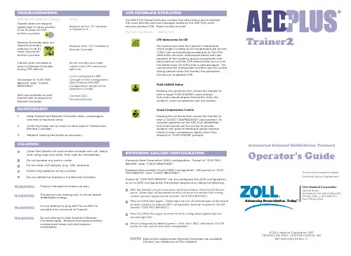
Show current scenario selection (press once) Start scenario (press again)
CPR Metronome set up to beep or not beep
(Real CPR Help® during CPR interval)
MAINTENANCE
1.
Keep Trainer2 and Remote Controller clean, undamaged,
and free of excessive wear.
2.
Verify that there are no cracks or loose parts in Trainer2 and
TROUBLESHOOlem / display:
Trainer2 does not respond
(green light in status window
is not lit) when On/Off
button is pushed
On
Off
Remote Controller does not respond (scenario selection is not lit) when view/enter button is pushed
© ZOLL Medical Corporation 2007 TRAINING USE ONLY - NOT FOR CLINICAL USE
REF 9650-XXXX-XX Rev. A
CONTROLS / INDICATORS Handheld Remote Controller:
Scenario Set-up Controls:
AirLink MP70高性能车载路由器说明书

Sierra Wireless EMBEDDED MODULES HL SERIES AirLink MP70 DatasheetAirLink® MP70 High Performance Vehicle RouterVehicle Grade, LTE-Advanced, Gigabit Wi-Fi The AirLink® MP70 is a high performance, LTE-Advanced vehicle router developed specifically for mission critical applications in public safety, transit and field services. Offering high power, long range Gigabit Wi-Fi and Gigabit Ethernet, and up to 300 Mbps downlink speeds over LTE-Advanced, the AirLink MP70 unites the fleet with the enterprise network and enables multiple field applications to work simultaneously, further and faster from the vehicle than ever before. The MP70 supports advanced remote visibility and instant insight into the vehicle area network (VAN), field applications and assets, and the mobile workforce. Purpose built for the vehicle, the MP70 delivers superior reliability and uninterrupted operation in harsh mobile environments.Secure, managed LTE networking for mission critical applicationsE-TicketingRecognitionVehicle Routers and Gateways Secure, Intelligent Communications Network ManagementHIGH PERFORMANCE VEHICLE AREA NETWORK (VAN)With dual-band Gigabit Wi-Fi and Gigabit Ethernet, the AirLink MP70 enables a complete portfolio of broadband mission critical applications to work simultaneously, further and faster from the vehicle than ever before.Built for first responders and field personnel, the MP70 offers up to 300 Mbps downlink speeds over LTE-Advanced, and up to 1.3 Gbps over 802.11ac Wi-Fi (with 3x3 MIMO) and Gigabit 4-port Ethernet. The AirLink MP70 can host up to 128 simultaneous Wi-Fi clients, and concurrently connect multiple mission critical applications in and around the vehicle including laptops, DVRs and tablets, in addition to providing live video streaming, and rapid and secure access to remote databases, such as record management systems.The AirLink MP70 supports 21 LTE frequency bands, enabling superior coverage on LTE networks worldwide. With automatic configuration of the radio based on the SIM, the AirLink MP70 has two product variants—one for LTE networks in North America, Europe, Middle East and Africa, and another variant to support all major LTE networks in Asia Pacific.Outside of the US, the AirLink MP70 offers dual-SIM functionality to enable automatic failover between SIMs, providing superior connectivity and cost optimization when roaming.CONNECTED VEHICLE AWARENESSThe AirLink MP70 increases efficiency, streamlines operations and reduces costsby supporting advanced remote visibility and instant insight into the vehicle area network (VAN), field applications and assets, and the workforce.Offering built-in vehicle-ready I/O, with the capacity to support AirLink Vehicle Telemetry, the MP70 enables remote monitoring of auxiliary devices such as light bars, sirens and gun racks, and can collect OBD-II vehicle telemetry data for engine diagnostics and performance data to monitor vehicle health.The MP70 offers an integrated mobile events engine to monitor hundreds of router, network, and connected vehicle parameters in real time, and create custom alerts, event triggers and reports. Reports and alerts are synchronized with third party server platforms or AirLink network management software to enable centralized and remote management of critical events.Utilizing next generation GNSS location technology that supports 48 satellites from 4 different satellite constellations (GPS, GLONASS, Galileo, Beidou), the MP70 provides fast, reliable and precise vehicle location, even in the most challenging environments. The MP70 contains an Inertial Navigation System1 that allows it to track without satellites, using dead reckoning algorithms integrated with the GNSS. The Inertial Navigation System continues to provide positioning information when the GNSS is unable to acquire satellites. This enables tracking through urban canyons, tunnels and underground parking.Location information can be streamed from the GNSS locally over the serial portto connected in-vehicle driver navigation and dispatch systems, and remotely over NMEA, TAIP, RAP and XORA protocols for integration with 3rd party applications.1activated in an upcoming software releasePURPOSE BUILT FOR VEHICLESThe MP70 provides superior reliability and continuous operation in harsh environments. It will survive extreme transient surges, and maintain continuous power during 5V brownouts and spikes from -600 VDC to 200 VDC.The AirLink MP70 safeguards vehicle operation by using built-in battery charge protection to monitor ignition state and battery voltage and, with a class leading power supply which meets and exceeds the requirements for E-Mark, ISO 7637-2 and SAEJ1455, the MP70 requires no additional power conditioning. Developed with industrial grade components, the AirLink MP70 has a customized die cast aluminum housing to manage the thermal output from its high performance LTE-Advanced and Wi-Fi radios. The MP70 is designed to meet IP64 for resistance to dust and water ingress, and is tested to meet and exceed the MIL-STD-810G specifications for shock, vibration, temperature and humidity. SECURE, INTELLIGENT COMMUNICATIONS The AirLink MP70 provides consolidated data security for all field applications and mobile assets in the vehicle area network (VAN). Offering up to 5 concurrent VPN sessions, the AirLink MP70 enables secure communications to multiple back-end systems, and provides remote authentication management to allow the implementation of enterprise-grade systems to control access to devices in the field. Secure signing and authentication of software images offers end-to-end protection of the software upgrade process, protecting the MP70 against unwanted malware. NETWORK MANAGEMENT Network Management solutions for the MP70 allow over-the-air registration, configuration and software updates for all AirLink gateways and routers, and can be deployed either as a hosted cloud-based service, or as a licensed software platform in the enterprise data center. Both options provide a centralized and remote view of an entire vehicle fleet and enable simplified management, control and monitoring of connected MP70s, field applications and mobile assets. AirLink Management Service (ALMS) is a secure, centralized cloud-based service that remotely monitors and manages signal strength, network technology and location. ALMS provides dashboards with up-to-date views of an entire deployment, and custom alerts to monitor and report critical events, to increase efficiency and prevent downtime.oMM Management System (oMM) is a licensed, unified software platform which can be deployed in the enterprise data center, and provides a consolidated network view of an entire fleet, using a virtual dashboard to monitor, report, manage, and troubleshoot all mobile resources as required.DASHBOARDSOFTWARE UPGRADES/UPDATESMONITOR CONNECTIVITYSECURITY CONFIGURATION2 activated in an upcoming software releaseNorth America and EMEA Model (Sierra Wireless MC7455) Carrier Approvals: Verizon, AT&T, T-Mobile USA Other major carriers pending Supported Frequency BandsLTE: 2100(B1), 1900(B2), 1800(B3), AWS(B4), 850(B5), 2600(B7), 900(B8), 700(B12), 700(B13), 800(B20), 1900(B25), 850(B26), 700(B29), TDD B41WCDMA: 2100(B1), 1900(B2), 1800(B3), AWS(B4), 850(B5), 900(B8)Industry Approvals: FCC, IC, PTCRB, R&TTE, GCF, CEAutomatic Network Operator Switching based upon SIM Dual SIM Functionality (2FF SIM)APAC Model (Sierra Wireless MC7430) Supported Frequency BandsLTE: 2100(B1), 1800(B3), 850(B5), 2600(B7),900(B8), 850(B18), 850(B19), 1500(B21), 700(B28), TDD Bands 38, 39, 40, 41WCDMA: 2100(B1), 850(B5), 800(B6), 900(B8), 1700(B9), 850(B19), TD-SCDMA B39 Industry Approvals: RCMAutomatic Network Operator Switching based upon SIM Dual SIM Functionality (2FF SIM)USB 2.0 Micro-B Connector6 SMA antenna connectors (cellular, diversity, GNSS, 3x3 Wi-Fi) Active GNSS antenna supportWPA2 EnterpriseHigh output power 21 dBm (per chan) 3x3 MIMO (Reverse Polarity SMA Connectors) Simultaneous AP/Client Mode (2.4 GHz) WiFi as WAN Mode1 Digital Open Collector Output > sinking 500 mA 3 Analog Inputs: 0.5-36 VDCConfigurable Pull-ups for dry contact input VLANHost Interface Watchdog PPPHost Port Routing NEMO/DMNR VRRPReliable Static RouteSplit TunnelDead Peer Detection (DPD)Remote Authentication (LDAP, RADIUS, TACACS+) DMZInbound and Outbound Port filtering Inbound and Outbound Trusted IP MAC Address Filtering PCI compatibleReports: NMEA 0183 V3.0, TAIP, RAP, XORA Multiple Redundant Servers Reliable Store and ForwardRouter staging over the air and local Ethernet connection Over-the-air software and radio module firmware updates Device Configuration Templates Configurable monitoring and alertingRemote provisioning and airtime activation (where Event Types: Digital Input, Network Parameters, Data Usage, Timer, Power, Device Temperature and VoltageReport Types: RAP, SMS, Email, SNMP Trap, TCP (Binary, XML, CSV)Event Actions: Drive Relay OutputSMS CommandsBuilt-in protection against voltage transients including 5 VDC engine cranking and +200 VDC load dump Humidity: 90% RH @ 60°CMilitary Spec MIL-STD-810G conformance to shock, vibration, thermal shock, and humidity IP64 rated ingress protectionISO7637-2, SAE J1455 (Shock, Vibration, Electrical) Environmental: RoHS2, REACH, WEEE1-day Accelerated Hardware Replacement available through In the box: DC Power Cable and Quick Start Guide----About Sierra Wireless Sierra Wireless is building the Internet of Things with intelligent wireless solutions that empower organizations to innovate in the connected world. We offer the industry’s most comprehensive portfolio of 2G, 3G, and 4G embedded modules and gateways, seamlessly integrated with our secure cloud and connectivity services. OEMs and enterprises worldwide trust our innovative solutions to get their connected products and services to market faster. Sierra Wireless has more than 950 employees globally and operates R&D centers in North America, Europe, and Asia. For more information, visit .。
AADvance Configuration Guide(配置手册)
Document no. 553633 Issue 1: February 2009
iii
Configuration Guide
WARNING
ELECTRICAL ARCS AND EXPLOSION RISK
Do not remove wiring, modules or communications cabling while circuit is live unless area is known to be non hazardous.
Failure to follow these instructions may result in personal injury.
CAUTION
Caution notices call attention to methods and procedures which must be followed to avoid damage to the equipment.
SAFETY Note
This symbol calls attention to items which must be considered and implemented when designing and building a safety system using the AADvance range of products.
If you connect or disconnect wiring, modules or communications cabling while power is applied, an electrical arc can occur. This could cause an explosion in hazardous location installations. Be sure that power is removed or the area is nonhazardous before proceeding.
数字有线电视网络手动搜台指南说明书
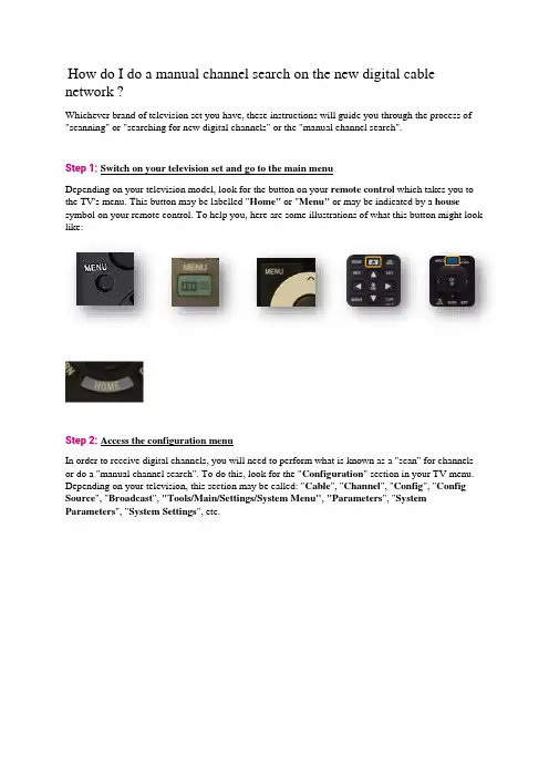
How do I do a manual channel search on the new digital cable network ?Whichever brand of television set you have, these instructions will guide you through the process of "scanning" or "searching for new digital channels" or the "manual channel search".Step 1:Switch on your television set and go to the main menuDepending on your television model, look for the button on your remote control which takes you to the TV's menu. This button may be labelled "Home" or"Menu" or may be indicated by a house symbol on your remote control. To help you, here are some illustrations of what this button might look like:Step 2:Access the configuration menuIn order to receive digital channels, you will need to perform what is known as a "scan" for channels or do a "manual channel search". To do this, look for the "Configuration" section in your TV menu. Depending on your television, this section may be called: "Cable", "Channel", "Config", "Config Source", "Broadcast", "Tools/Main/Settings/System Menu", "Parameters", "System Parameters", "System Settings", etc.Here are some illustrations to help you (the following illustrations have been taken from a "Samsung" television". However, the steps remain the same for all brands of television):Step 3:Select the installation optionThen select"Channels","Index", "Installation", "Installation Programme", "Install channels", "Parameters", "System Parameters", "Channel Search", "Digital Settings", "Rescan" "Scan", etc.Step 4:Select the option to search for digital channelsTo carry out a "scan" or perform a "manual channel search", you need to look for the manual channel search option amongst the available settings. If this option is not available, carry out an automatic channel searchThe channel search function may have different names, such as: "Search Assistant", "Auto Installation", "Automatic/Operator Scan", "Auto System Configuration", "Clear Channels", "Aerial/Cable/Service Installation", "Auto Digital Store", "Channel Settings", "Reinstall/Search All Channels", "Automatic Digital Channel Search", "Automatic Digital Cable Network Search", "Manual DVB-C Search", "Factory/Manual Digital Settings", "Reinitialise Channels/TV", "Reinstall everything", "Reset to startup settings", "Cable synchronisation", etc.Please note! Do not choose updateSome television models will ask you if you want to perform a scan for digital or analogue channels. Here you want to search for digital channels.The television might ask you if you want to search for channels via the aerial or via the cable network. In all cases, you want to search via the cable network.Step 5:Enter your password if the television requests itIt's possible that the television will ask you to enter a password during this process. If you know your password, enter it now. If you don't know the password, try: "0000", "1111", "1234", "8888", "9999".If your equipment warns you that all your previous channels will be deleted, this is normal.Step 6:Set the channel search settingsWhen you have found the right section, you should be on a configuration page with some settings which can be modified. Here are some general indications of what you might be asked:Reference table:Step 7:Start a channel searchOnce you have entered these settings, you can start a search by pressing "Start Scan", "Start ATP", "Start", or "Search",Wait until the process is complete. This can take several minutes.Step 8:Exit the installation menuPress "Back", "Confirm", "Exit", "Menu" or "Complete" to exit the installation menu.Step 9:Check that the scan has returned the correct channelsYou will now be asked to go to Channel 99. You should see the following screen:If you see this screen, you have completed the scan and now have access to cable television.。
易于管理的 Wi-Fi 来宾网络 快速生成安全的来宾通行证说明书

NetworkingSimplified Wi-fi GueSt AcceSS mAnAGementGuest pass generation made simple and secure in under 60 seconds.Ruckus Guest Networking radically simplifies the setup and management of wireless LAN (WLAN) access for guests, contractors and other temporary WLAN users.Guest networking is an essential capability required forenterprises, healthcare organizations, schools, hotels and local “hotzones” such as airports, restaurants and other venues that want to provide Internet connectivity to a myriad of guests while controlling access times, privileges and bandwidth consumption. An integrated capability within every Ruckus ZoneDirector™ Smart WLAN controller, Ruckus Guest Networking is a highly intuitive, browser-based facility that lets any guest-facing staff generate a unique Wi-Fi guest pass in less than 60 seconds with no configuration changes required on any client device.Since the guest WLAN uses the same enterprise infrastructure that carries internal traffic, Ruckus Guest Networking segregates guest traffic from corporate traffic while providing IT administra-tors controls for limiting bandwidth and the amount of connection time that guests can access the network.Guest Pass authentication enables enterprises and hotzone providers to generate time-limited access passes in hour, day, and week increments allowing more granularity between different types of guests.Highly flexible, unique pass keys can be dynamically generated by the ZoneDirector for a single guest or in batch for a large group of guests, where each key is bound to a specific clientfeAtuReS/BenefitSSimple, browser-based guest pass generationIn less than a minute, any guest-facing staff can generate single or multiple guest passes from a centrally-hosted URL through an intuitive, point-and-click, menu-driven interface, freeing IT administrators from this tasktime-limited guest accessAdministrators can simply and easily limit the time of guest passes forcing them to expire in hours, days or weeks from when the pass is created or from when the user first logs inflexibleOperators can create a guest pass on demand, orgenerate multiple passes by uploading a list of guests — if they want to be able to identify the guest pass users by their names (for monitoring or auditing purposes in a hotel). Pass keys can be random, system-generated values, or they can be defined by the operator as an easy-to-remember phrase.customizableAdministrators can customize the Guest Pass Portal with their company logo, terms of use and login instructionsAutomatic guest redirectionAfter agreeing to terms and conditions, users can be au-tomatically redirected to a custom Web page or directed to the requested URLRestricted subnet accessGuest pass users can be automatically blocked from accessing pre-defined subnets, leaving enterprise users unaffected by guest usageBandwidth thresholds per SSidAdministrators can limit capacity for a given guest network (SSID) as well as bandwidth per user within a given guest networkAcceSS mAnAGementportals are customizable with the organization’s logo and welcome text can be customized into any language. Print a single guest pass or print all of them. (see Figure 3: Step 2a and Step 2b).MAC address upon successful authentication. A single pass key can also be shared among many users. Keys can be randomly generated values, or the operator can specify an easy to remember phrase. Unlike other solutions, no additional appliances are needed.enterprise and Guest SecurityGuest WLANs can be created without requiring special con-figuration of authentication and encryption settings on client devices to minimize guest connectivity problems (see Figure 1).The Guest WLAN provides authentication services while the wireless client isolation option prevents clients on the same WLAN from communicating with each other (see Figure 2). Guests can be automatically blocked from accessing any or all of the subnets connected through the ZoneDirector and its managed access points (APs).When APs are on subnets different from the ZoneDirector, the administrator can block guest users from accessing these subnets by adding access restrictions for them.Additionally, IT administrators can limit the bandwidth for the guest WLAN to ensure sufficient performance for employee applications. The guest is placed on the guest virtual LAN and all its traffic is sent directly to the Internet, or bypassing the ZoneDirector, thereby preventing a bottleneck in the network.Guest Account creationSimple-to-use menus guide front desk staff and other guest-facing personnel through the process of creating single or multiple guest passes. For a single guest pass enter the guest user name, specify the time period (days, hours, or weeks), WLAN, optional remarks, and use the ZoneDirector randomly generated key or change it to a customized key between one and 16 ASCII characters (see Figure 3; Step 1a). Or choose multiple guest passes and specify the time period, WLAN, and the number of guest passes or upload a file with guest pass user names, remarks, and customized keys (see Figure 3; Step 1b).For example, contractors can receive extended access to the network, while a visitor can get access only for the day. This minimizes inconvenience for the guest while maximizing enterprise security.The guess pass printout is a printable HTML page that contains all the login information needed for the guest to use the WLAN and connection instructions for Windows. Ruckus Guest PassFigure 1: A single Web-based screen that lets administrators point-and-click through a variety of optionsFigure 2: IT administrator enables guest WLANRuckus Wireless, Inc. 350 West Java DriveSunnyvale, CA 94089 USAAcceSS mAnAGementThe Ruckus ZoneDirector provides comprehensive guest management for monitoring, tracking, and removing guestaccounts. The IT administrator can receive a list of all generated guest passes, and a log tracks when guests joined and left the guest WLAN. The ZoneDirector shows all authorized and unauthorized guests.When a guest has a problem connecting to the WLAN, theadministrator can easily see if that user has successfully entered the guest pass. The IT administrator can deal with threats by removing any guest pass and blocking any client device attempting to connect to the WLAN APs. A historical log of all blocked clients is maintained over time for the IT administrator.Guest pass portalWhen guests on a pre-defined guest SSID open a browser to connect to the Internet, they are redirected to captive portal page hosted on the Ruckus ZoneDirector, requesting login credentials (see Figure 3: Step 3). Ruckus Guest Pass portals are customizable with the organization’s logo and welcome text.Once a valid pass key is entered, a terms of use agreement page (optional) is sent to the guest for acceptance. Uponacceptance, guests can be redirected to a specific URL or sent to the originally requested Web site.Guest WlAn managementIT administers the guest pass generation rights to employees and selection of authentication servers to validate their login to the ZoneDirector.Copyright © 2012, Ruckus Wireless, Inc. All rights reserved. Ruckus Wireless and Ruckus Wireless design areregistered in the U.S. Patent and Trademark Office. Ruckus Wireless, the Ruckus Wireless logo, BeamFlex, ZoneFlex, MediaFlex, MetroFlex, FlexMaster, ZoneDirector, SpeedFlex, SmartCast, and Dynamic PSK are trademarks of Ruckus Wireless, Inc. in the United States and other countries. All other trademarks mentioned in this document or websiteFigure 3: Simplified setup of guest portalStep 2a: Single Guest Access Generated Step 1b: Multiple Guest Pass CreationStep 1a: Single Guest Pass CreationF o r m o r e i n f o r m a t i o n , p l e a s e c a l l 877.449.0458, o r e m a i l u s a t S a l e s @C o r p o r a t e A r mo r .c o m .。
千兆光猫用户手册说明书
The CODA-5519is a powerful router that will be used as the heart of your wireless home.It will offer strong Wi-Fi that will covers most houses.The CODA-5519has the capability to receive 5Gbps bi-directional based on 2OFDM +32QAM downstream channels and with 2OFDMA +8upstream channels over its DOCSIS 3.1interface.The integrated Wi-Fi 4x42.4GHz 802.11ax and 4x45GHz 802.11ax dual band MU-MIMO Access Point significantly improves customer experience extending range and coverage with blazing speeds.For wired clients,2.5G plus two Gigabit Ethernet ports offer ultra-fast connection.It can be paired with Hitron extenders/mesh pods for extra coverage.•DOCSIS 3.1 2x2 multi-carrier OFDM •DOCSIS 3.0 32x8 channel bonding•4x4 2.4GHz 802.11ax and 4x4 5GHz 802.11ax dual band concurrent MU-MIMO internal antennas •16 SSIDs (8SSIDs per radio)•Individual configuration for each SSID (security, bridging, routing, firewall and Wi-Fi parameters)•Extensive operator control via configuration file and SNMP•Integrated DLNA Media Server with support for video, audio and image servingDOCSIS 3.1 Wi-Fi 6 and eMTA GatewayIntel® Puma™ 7 OFDM 2x2 w / fixed upstream, 4x4 dual band Wi-Fi w/ concurrent 802.11ax 2.4Ghz + 5GHz, MoCA 2.0 channel bonding and voice HIGH PERFORMANCE INTERNET AND WIRELESS ACCESSThe CODA-5519supports pre-configured and pre-enabled Wi-Fi security via Wi-Fi Protected Setup (WPS),allowing the end-user to rapidly set up a secure wireless network without manual configuration.Hitron's AutoSync software provides secure automated setup of extenders in the customer's home or business.It comes with MyHitron (end user management mobile application).MSO can also get extra management and analytics via HitronCloud/OptiMy CSR interface from the support center.SECURE WIRELESS NETWORKING CONTROLLED AT THE TIP OF YOUR FINGERSKEY FEATURES•IPv6 routing•MoCA 2.0 channel bonding•TR-069 and HNAP for easy setup and remote management•Enhanced management and stability for low total cost of ownership•One 2.5G and Two 1G Ethernet ports •Hitron Ecosystem Support (OptiMy, HitronCloud, MyHitron)•2 HD voice ports with SIP or MGCP supportTVStreamer Smartphone TabletThermostatHome Security LaptopCODA-5519Printer PCMoCA ExtenderPhonesWi-Fi1G Ethernet Analog2.5G Ethernet Coax PodLaptop Gaming ConsoleConnectivity•RF F-Type 75Ωfemale connector•2x RJ-45 Ethernet port 10/100/1000Mbps•1x RJ-45 Ethernet port 10/100/1000/2500Mbps•USB 3.0 type A connector with host interface•2x RJ-11 HD voice ports•EBBU jackManagement•Protocol support: TR-069, TFTP, SSHv2, SNMP v2C, v3•Web-based GUI control, configuration and management •Power-on self diagnostic•Hitron proprietary MIBs for extended support onDOCSIS, router management, Wi-Fi managementand MoCA management•app support•and back end supportReception-Demodulation•DOCSIS 3.1/3.0/2.0•DOCSIS 3.1 demodulation: Multi-carrier OFDM 16 to 4096QAM •DOCSIS 3.1 data rate: Up to 5Gps with 2 OFDM 192MHz downstream channels +32 QAM•DOCSIS 3.0 demodulation: 64QAM, 256QAM•DOCSIS 3.0 data rate: Up to 1.2Gbps with 32 bonded downstream channels•Frequency (edge-to-edge): 108-1218MHz and 258-1218 •Channel Bandwidth: 6MHz•Signal level: -15dBmV to 15dBmVTransmitter-Modulation•DOCSIS 3.1/3.0/2.0•DOCSIS 3.1 modulation: Multi-carrier OFDMA BPSK to 4096QAM •DOCSIS 3.1 data rate: Up to 700Mbps with OFDMA 96MHz upstream channels•DOCSIS 3.0 modulation: QPSK, 8QAM, 16QAM, 32QAM, 64QAM, and 128QAM (SCDMA only)•DOCSIS 3.0 data rate: Up to 320Mbps with 8 bonded upstream channels•Frequency: Fixed 5-85MHz•Upstream transmit signal level: +11 to 65dBmVMoCA 2.0 Reception / Transmitter-Modulation •Demodulation/ Modulation: BPSK, QPSK, 8QAM, 16QAM,32QAM, 64QAM, 128QAM, 256QAM, 512QAM, 1024QAM •PHY data rate: 700Mbps (baseline Mode) / 1400Mbps (bonding channel)•Throughput: 400+Mbps (baseline mode) / 500+Mbps (turbo mode, point to point) / 800Mbps (bonding channel)•Frequency (center frequencies): 1400-1625MHz•Channel bandwidth: 100MHz (baseline mode) / 225MHz (bonding channel)Voice•Protocol support: SIP or MGCP•2x 8kHz each HD voice•Audio codecs: G.711 (a-law and mu-law), G.722 (HD codec), G.723.1, G.726, G.728, and G.729Routing Support•Protocol support: IGMP v3 for IPTV service capability•MAC address filtering (IPv4/IPv6)•IP source/destination address filtering (IPv4/IPv6)•DHCP, TFTP and ToD clients (IPv4/IPv6)•DHCP server supports RFC 1541 (IPv4)•DHCPv6 obtains prefix from DHCPv6 server through prefix delegation•Firewall with stateful inspection (IPv4/IPv6)•Hacker intrusion prevention and detection•Application content filtering (IPv4/IPv6)•Complete NAT software implemented as per RFC 1631 with port and address mapping (IPv4)•DSLite support for IPv4 in-home support with IPv6 MSO backbone •6RD support for quick IPv6 deployment over IPv4 backbone •RIPv2 for static IP supportWireless•802.11a/b/g/n/ac/ax•4T4R 2.4GHz 11ax and 4T4R 5GHz 11ax dual band concurrent MU-MIMO with 1Gbps+4.8Gbps PHY rate•20/40/80/160MHz channel bandwidth•Up to 8 SSIDs for each frequency•Security: WPA-PSK/WPA2-PSK (TKIP/AES), WPA3, WAPI •QoS: WMM/WMM-PS•WPS (Wi-Fi Protected Setup) PBC, PIN•Airtime Fairness (ATF), Band Steering (BS)•Dynamic Frequency Selection (DFS)•Wi-Fi output power range: Max permitted by FCC/IC Electrical•Input power: 12VDC, 4A•Power adaptor: 100-240VAC, 50/60Hz•Power consumption: 4.92 (power saving), 22W (typ.), 38W (Max)•Support power outage for 24 hours on Hitron external battery •Surge protection: RF input sustains at least 4KVEthernet RJ-45 sustains at least 4KV Mechanical•Factory default reset button•WPS button•Dimensions: 74.3mm (W) x 251.5mm (H) x 230.8mm (D)•Weight: Weight: 1850 ±10gEnvironmental•Operating temperature: 0°C (32°F) ~ 40°C (104°F)•Operating humidity: 10% ~ 90% (Non-condensing)•Storage temperature: -40°C (-40°F) ~ 60°C (140°F) Compliance Certificates•RoHS compliant•FCC, IC, ULSPECIFICATIONS。
配置说明书
Step 28. Select Latch Type SubmenuPress d to display flashing DSBL / ENBL .If flashing DSBL is displayed, press a , if ENBL is displayed, press b until DSBL is displayed, then press d to store and go to the next menu item.Step 29. Select the Above Type of Active Submenu Press d . If flashing ABoV Above is displayed, press a ,otherwise press b until ABoV is displayed. Press d to store and advance to next menu item.Step 30. Select the Deadband Value Submenu Press d . The display will show 020.0, otherwisepress b or c.Press d to store and advance to next menu item.Step 31. Enter the Alarm 2 MenuThe display will show ALR2the top menu for Alarm 2.Repeat steps from 29 and 30 to set for Alarm 2 the same conditions as for Alarm 1.Step 32. Configuration of Display Color Selection Press a until the COLR Display Color Selection Menu appears on the Display. Configure COLR as N.CLR / GRN (green), 1.CLR / RED (red), 2.CLR / AMBR (amber). Please refer to the operator’s manual if needed.Step 33. Run a TestPress a until reset the controller and return to RUN Mode to display 075.0(Ambient Temperature). Now you are ready to observe temperature as it rises 10°F higher than displayed. Touch the tip of the Thermocouple to raise the temperature above the Alarm 2 value 082.0, and AL2 will turn on, and Display Color will change from Green toAmber. Continue touching the tip to raise the temperature above the Alarm 1 value 087.0and Display Color will change from Amber to Red.Step 10. Enter to the Thermocouple Input Submenu Press d to store Thermocouple Input. The display will stop flashing and show the top menu for Thermocouple types. If you press a controller will step to next menu item (Skip to Step 14).Step 11. Enter to the Thermocouple Type Input Submenu Press d to display flashing, previously selected Thermocouple type.Step 12. Scroll through available selection of TC types Press b to sequence thru flashing Thermocouple types,(select k -for type "K" CHROMEGA ®/ALOMEGA ®)J K T E N DIN J R S B C - TC types J k t E N dN J R S b C - DisplayStep 13. Store TC typeAfter you have selected the Thermocouple type press d to store your selection, the instrument automatically advances to the next menu item.Step 14. Enter to Reading Configuration MenuThe display shows RDG Reading Configuration, which is the top menu for 4 submenus: Decimal Point, Degree Units,Filter Constant and Input/Reading Submenus.Step 15. Enter to Decimal Point Submenu Press d to show DEC Decimal Point.Step 16. Display the Decimal Point positionPress d again to display the flashing Decimal Point position.Step 17. Select the Decimal Point position Press b to select FFF.F Decimal Point position.Step 18. Store selected Decimal Point positionBy pressing d momentarily the Decimal Point position will be stored and the instrument will go to the next menu item.Step 19. Enter to Temperature Unit Submenu Display shows TEMP Temperature Unit.Step 20. Display available Temperature Units Press d to display the flashing Degree °F or °C .Step 21. Scroll through Temperature Units selection Press b to select °F Degree.Step 22. Store the Temperature UnitPress d to display momentarily that the Degree Unit has been stored and the instrument will go automatically to the next menu item.Step 23. Enter the Filter Constant Submenu Display shows FLTR Filter Constant Submenu.Step 24. Display the Filter Constant Value Submenu Press d to display the flashing, previously selected Filter Constant.Step 25. Scroll through available Filter Constants Press b to sequence thru Filter Constants 0001, 0002,0004, 0008, 0016, 0032, 0064and 0128.Step 26. Store the Filter ConstantPress d momentarily to store 0004Filter Constant and the instrument will automatically go to the next menu item.Step 27. Enter Alarm 1 MenuPress a until the ALR1Alarm 1 Menu appears on the Display. In the following steps we are going to DisableLatch, Active Above, Deadband 020.0, and above Setpoint 1Value will activate Alarm 1.MQS3846/N/0905SPECIFICATIONAccuracy:+0.5°C temp;0.03% rdg. process typical Resolution:1°/0.1°; 10 µV process Temperature Stability:0.04°C/°C RTD;0.05°C/°C TC @ 25°C (77°F); 50 ppm/°C process Display:4-digits, 9-segments LED,10.2 mm (0.40") with red, green and amber programmable colors Input Types:Thermocouple, RTD, Analog Voltage and Current TC:(ITS90)J, K, T, E, R, S, B, C, N, L RTD:(ITS68)100/500/1000 ohm Pt sensor 2-wire, 3-wire, or 4-wire;0.00385 or 0.00392 curve Voltage:0 to 100 mV, 0 to 1 V, 0 to 10 Vdc Current:0 to 20 mA (4 to 20 mA)Output 1†:Relay 250 Vac @ 3 A Resistive Load,SSR, Pulse, Analog Voltage and Current Output 2†:Relay 250 Vac @ 3 A Resistive Load,SSR, Pulse †Only for AlarmsOptions:Communication RS-232 / RS-485 or 10BaseT or Excitation:24 Vdc @ 25 mAExc. not available for Low Power OptionLine Voltage/Power:90 - 240 Vac ±10%,50 - 400 Hz*,or 110-375 Vdc, 4W for i16; 5W for i16D* No CE compliance above 60 HzLow Voltage Power Option:12 - 36 Vdc, 3 W** for i16;20 - 36 Vdc, 4 W** for i16D;**Units can be powered safely with 24 Vac but No Certification for CE/UL are claimed.Dimensions:48 H x 48 W x 127 D mm (1.89 x 1.89 x 5")Weight:159 g (0.35 lb)Approvals:CE per EN 61010-1:2001NEWPORT is constantly pursuing certification of its products to the European New Approach Directives.NEWPORT will add the CE mark to every appropriate device upon certification.The information contained in this document is believed to be correct, but NEWPORT Electronics, Inc.accepts no liability for any errors it contains, and reserves the right to alter specifications without notice.TRADEMARK NOTICE:,NEWPORT , NEWPORT , ,andthe “Meter Bezel Design”are Trademarks of NEWPORT ELECTRONICS, INC.This Quick Start Reference provides informationon setting up your instrument for basic operation.The latest complete Communication and OperationalManual as well as free Software and ActiveX Controlsare available at /i or on theCD-ROM enclosed with your shipment.SAFETY CONSIDERATIONThe instrument is a panel mount device protected in accordance with EN61010-1:2001. Remember that the unit has no power-on switch. Building installation should include a switch or circuit-breaker that must be compliant to IEC 947-1 and 947-3.SAFETY:•Do not exceed voltage rating on the label located onthe top of the instrument housing.•Always disconnect power before changing signal andpower connections.•Do not use this instrument on a work bench withoutits case for safety reason.•Do not operate this instrument in flammable orexplosive atmospheres.•Do not expose this instrument to rain or moisture. EMC:•Whenever EMC is an issue, always use shielded cables.•Never run signal and power wires in the same conduit.•Use signal wire connections with twisted-pair cables.•Install Ferrite Bead(s) on signal wire close to theinstrument if EMC problems persist.Panel Mounting Instruction:ing the dimensions from the panel cutout diagramshown above, cut an opening in the panel.2.Insert the unit into the opening from the front of the panel,so the gasket seals between the bezel and the front of the panel.3.Slide the retainer over the rear of the case and tightenagainst the backside of the mounting panel.。
远程SIM配置用户手册说明书
RemoteSIM Configurations User ManualMarch2023Introduction3 Requirements3 Scenario1:SIM Injector in LAN of Cellular Router4 Setup topology4 Configuring the SIM Injector/SIM Injector Mini4 Configuring the Cellular Router5 Scenario2:SIM Injector in WAN of main Router and multiple Cellular Routers8 Setup topology8 Additional configurations for Cellular Routers8 Configuration requirements for the main Router10 Scenario3:SIM Injector in LAN of main Router and multiple Cellular Routers11 Setup topology11 Main Router configuration12 Scenario4:SIM Injector in LAN of main Router and Dome with Starlink13 Setup topology13 Configuring the MAX HD2router14 Configuring the SIM Injector15 Configuring the HD1Dome Pro16 Scenario5:SIM Injector/SIM Injector Mini in a remote location18 Setup topology18 Cellular Router configuration18 How to check if a Peplink Cellular Router supports RemoteSIM20 Monitor the status of the RemoteSIM20 Appendix A:Declaration21IntroductionPeplink has developed a unique technology called RemoteSIM,which allows SIM cards to remotely link to a cellular router.This can be done via cloud or within the same physical network.There are a few key scenarios to fit certain applications.The purpose of this manual is to provide an introduction on where to start and how to set up for the most common scenarios and uses.Requirements-Cellular router that supports RemoteSIM technology.-SIM Injector.-SIM card.Notes:-Always check for the latest Firmware version for both the cellular router and the SIM Injector.You can also check for the latest Firmware version on the device’s WEBconfiguration page.-A list of products that support RemoteSIM can be found on the SIM Injector WEB page.Please check under the section Supported models.SIM Injector reset and login detailsHow to reset a SIM Injector:-Hold the reset button for5-10seconds.Once the LED status light turns RED,the reset button can be released.SIM Injector will reboot and start with the factory default settings. The default WEB login settings:-User:admin-Password:admin-IP address:the device only has a DHCP client and no fallback IP address..Therefore,it is advised to check every time what IP address is assigned to the SIM Injector.Notes:-The SIM Injector can be monitored via InControl2.Configuration is not supported.Scenario1:SIM Injector in LAN of Cellular RouterSetup topologyThis is the most basic scenario in which the SIM Injector/SIM Injector Mini(hereinafter referred to as SIM Injector)is connected directly to the cellular router’s LAN port via an ethernet cable. This allows for the cellular router to be positioned for the best possible signal.Meanwhile,the SIM cards can be conveniently located in other locations such as the office,passenger area,or the bridge of a ship.The SIM Injector allows for easily swapping SIM cards without needing to access a cellular router.IMPORTANT:Cellular WAN will not fallback to the local SIM if it is configured to use the SIM Injector.Configuring the SIM Injector/SIM Injector Mini1.Connect the SIM Injector to the LAN port of the cellular router.2.Insert SIM cards into the SIM Injector.The SIM cards will be automatically detected. IMPORTANT:SIM cards inserted into SIM Injector must not have a PIN code.Note1:The SIM Injector gets its IP address via DHCP and doesn't have a static IP address.To find it’s address,please check the DHCP lease on the cellular router.Configuring the Cellular RouterStep1.Enable the SIM Injector communication protocol.1a.If you are using a Balance cellular router,go to the Network tab(top navigation bar).1b.If you are using a MAX cellular router,go to the Advanced tab(top navigation bar).2.Under Misc.settings(left navigation bar)find Remote SIM Management.3.In Remote SIM Management,click on the edit icon next to Remote SIM is Disabled.4.Check the Auto LAN discovery checkbox and click Save and Apply Changes.5.Click Save and then Apply Changes.Step2.Enable RemoteSIM for the selected Cellular interface.1.Go to Network(top navigation bar),then WAN(left navigation bar)and click Details for a selected cellular WAN.This will open the WAN Connection Settings page.2.Scroll down to Cellular settings.3.In the SIM Card section,select Use Remote SIM Only.4.Enter configuration settings in the Remote SIM Settings section.Click on Scan nearby remote SIM server to show the serial number(s)of the connected SIM Injector(s).Available configuration options for cellular interface are shown below:A.Defining SIM Injector(s)-Format:<S/N>-Example1:1111-2222-3333-Example2:1111-2222-33334444-5555-6666B.Defining SIM Injector(s)SIM slot(s):-Format:<S/N:slot number>-Example1:1111-2222-3333:7,5(the Cellular Interface will use SIM in slot7,then5)-Example2:1111-2222-3333:1,21111-2222-3333:3,4(the cellular Interface will use SIM in slot1,then in2from the first SIM Injector,and then it will use3and4from the second SIM Injector).Note:It is recommended to use different SIM slots for each cellular interface.5.Click Save and Apply Changes.Step3.(Optional)Custom SIM cards settings.1a.For a Balance router,go to the Network(Top tab).1b.For a MAX router,go to the Advanced(Top tab).2.Under Misc.settings(Left-side tab)find Remote SIM Management.3.Click on the Add Remote SIM button,fill in all the required info and click Save.This section allows defining custom requirements for a SIM card located in a certain SIM slot: -Enable/Disable roaming(by default roaming is disabled).-Add Custom mobile operator settings(APN,user name,password).4.Repeat configuration for all SIM cards which need custom settings.5.Click Apply Changes to take effect.Scenario2:SIM Injector in WAN of main Router and multiple Cellular RoutersSetup topologyIn this scenario,each HD Dome creates a WAN connection to the main router.A single SIM Injector is used to provide SIM cards for each HD Dome.The HD Dome can be replaced with any Peplink cellular router supporting RemoteSIM technology.This scenario requires the completion of the configuration steps shown in Scenario1in addition to the configuration steps explained below.Additional configurations for Cellular RoutersStep1.Disable the DHCP server.-HD Dome1should act as a DHCP server.-HD Dome2should be configured to have a static IP address with DHCP disabled.-Both routers should be in the same subnet(e.g.192.168.50.1and192.168.50.2).1.Go to Network(Top tab),then Network Settings(Left-side tab),and click on Untagged LAN.This will open up the LAN settings page.2.Change the IP address to192.168.50.2.3.In the DHCP Server section,uncheck the checkbox to disable DHCP Server.4.Click Save and Apply Changes.Step2.Ethernet port configurationThe Ethernet port must be set to ACCESS mode for each HD Dome.To do this,dummy VLANs need to be created first.1.Go to Network(Top tab),then Network Settings(Left-side tab),and click on New LAN.This will open the settings page to create a dummy VLAN.2.The image below shows the values that need to be changed to create a new VLAN:Note:set different IP addresses for each HD dome(e.g.192.168.10.1and192.168.10.2).3.Click Save and Apply Changes.4.Go to Network(Top tab),then Port Settings(Left-side tab).5.Set the Port Type to Access and set VLAN to Untagged LAN(see picture below).6.Click Save and Apply Changes.Configuration requirements for the main RouterRequirements for the main router are:-Configure WAN1as a DHCP client.-WAN1will automatically get the Gateway IP address from HD Dome1.-Configure WAN2as a Static IP and set it to192.168.50.12.-Configure WAN2Gateway to192.168.50.2.Same as the HD Dome2’s IP address.Scenario3:SIM Injector in LAN of main Router and multiple Cellular RoutersSetup topologyIn this scenario,SIMs are provided to the HD Domes via the main router.In this example,the Remote SIM Proxy functionality needs to be enabled on the main router.Notes:-HD Dome can be replaced with any other cellular router that supports RemoteSIM.-It is recommended to use Peplink Balance series or X series routers as the main router.This scenario requires the completion of the configuration steps for the cellular router and the SIM Injector as in Scenario1.The configuration for the main router is explained below.Main Router configurationIMPORTANT:Main router LAN side and Cellular Routers must be configured using different subnets,e.g.192.168.50.1/24and192.168.100.1/24.Note:please make sure the Peplink router is running Firmware8.1.0or above.1.Open the main router WEB interface and change:From<IP address>/cgi-bin/MANGA/index.cgi to<IP address>/cgi-bin/MANGA/support.cgi.This will open the support.cgi page.2.Scroll down to find Remote SIM Proxy and click on[click to configure]that is located next to it.3.Check the Enable checkbox.4.Click on Save.5.Go back to the index.cgi page and click on Apply Changes.Scenario4:SIM Injector in LAN of main Router and Dome with StarlinkSetup topologyEquipment used:-HD1Dome Pro(MAX-HD1-DOM-PRO-5GD),FW version8.2.1-MAX HD2(MAX-HD2-LTEA-W-T),FW version8.2.1-SIM Injector Mini(SIM-MINI-8-1E),FW version1.1.120Configuring the MAX HD2routerIMPORTANT:Main router LAN side and Cellular Routers must be configured using different subnets,e.g.192.168.50.1/24and192.168.100.1/24.Step1.Change router subnet to192.168.100.1/24.1.Go to Network tab,then click on LAN network2.Change IP addresses to the new subnet:3.Click on Save.4.Go back to the index.cgi page and click on Apply Changes.Step2.Enable the Remote SIM Proxy1.Open the main router WEB interface and change:From192.168.100.1/cgi-bin/MANGA/index.cgi to192.168.100.1/cgi-bin/MANGA/support.cgi 2.Scroll down to find Remote SIM Proxy and click on[click to configure]that is located next to it.3.Check the Enable checkbox.4.Click on Save.5.Go back to the index.cgi page and click on Apply Changes.Configuring the SIM InjectorThere is no need to configure a SIM Injector mini.Once the HD2router configuration is finished you power on SIM Injector mini.IMPORTANT:in case SIM Injector Mini was connected to HD2before its configuration,then need to power off and then power on SIM Injector Mini.Configuring the HD1Dome ProStep1.Enable the SIM Injector communication protocol.1.By default the HD1Dome Pro IP address is192.168.50.1.Open WEB based configuration interface and then go to Advanced tab(top navigation bar).2.Under Misc.settings(left navigation bar)find Remote SIM Management.3.In Remote SIM Management,click on the edit icon next to Remote SIM is Disabled.4.Check the Auto LAN discovery checkbox and click Save and Apply Changes.5.Click Save and then Apply Changes and reboot the HD1Dome Pro.Step2.Enable RemoteSIM for the selected Cellular interface.1.Go to Network(top navigation bar),then WAN(left navigation bar)and click Details for a selected cellular WAN.This will open the WAN Connection Settings page.2.Scroll down to Cellular settings.3.In the SIM Card section,select Use Remote SIM Only.4.Click Scan nearby remote SIM server.The system must find the SIM Injector Mini serial number as shown below.5.Click Update RemoteSIM Settings.6.Click Save and Apply Changes.Step3.(Optional)Custom SIM cards settings.1.For a MAX router,go to the Advanced(Top tab).2.Under Misc.settings(Left-side tab)find Remote SIM Management.3.Click on the Add Remote SIM button,fill in all the required info and click Save.This section allows defining custom requirements for a SIM card located in a certain SIM slot: -Enable/Disable roaming(by default roaming is disabled).-Add Custom mobile operator settings(APN,user name,password).4.Repeat configuration for all SIM cards which need custom settings.5.Click Apply Changes to take effect.Scenario5:SIM Injector/SIM Injector Mini in a remote locationSetup topologyRequirements for installing a SIM Injector/SIM Injector Mini(hereinafter referred to as SIM Injector)in a remote location:●Cellular router communicates with the SIM Injector via UDP port50000.Therefore thisport must be reachable via public IP over the Internet.●The one way latency between the cellular router and the SIM Injector should be up to250ms.A higher latency may lead to instability issues.●The cellular router must have Internet connection to connect to the SIM Injector.It canbe another Internet connection via Ethernet or Fiber if possible,or a secondary cellular interface with a local SIM(Ignite SIM).●Due to its high latency,it is not recommended to use satellite WAN for connecting to aSIM Injector in remote locations.SIM Injector configuration is the same as in Scenario1.Cellular Router configurationStep1.Enable the SIM Injector communication protocol.1a.For a Balance cellular router,go to the Network(Top tab).1b.For a MAX cellular router,go to the Advanced(Top tab).2.Under Misc.settings(Left-side tab),find Remote SIM Management.3.In Remote SIM Management,click on the edit icon next to Remote SIM is Disabled.4.Enter the public IP of the SIM Injector and click Save and Apply Changes.Notes:-Do NOT check Auto LAN Discovery.-Adding a SIM Injector serial number to the Remote SIM Host field is a mistake! Step2.RemoteSIM and custom SIM card settings configurations are the same as in Scenario1.How to check if a Peplink Cellular Router supports RemoteSIM1.Go to Network(Top tab),then WAN(Left-side tab),and click Details on any cellular WAN. This will open the WAN Connection Settings page.2.Scroll down to Cellular settings.If you can see the Remote SIM Settings section,then the cellular router supports RemoteSIM.Monitor the status of the RemoteSIM1.Go to Network(Top tab),then WAN(Left-side tab),and click Details on the cellular WAN which was configured to use RemoteSIM.2.Check the WAN Connection Status section.Within the cell WAN details,there is a section for Remote SIM(SIM card IMSI,SIM Injector serial number and SIM slot).Appendix A:DeclarationFCC Requirements for Operation in the United StatesFederal Communications Commission(FCC)Compliance Notice:For SIM InjectorFederal Communication Commission Interference StatementAny changes or modifications not expressly approved by the party responsible for compliance could void your authority to operate the equipment.This equipment has been tested and found to comply with the limits for a Class B digital device, pursuant to part15of the FCC Rules.These limits are designed to provide reasonable protection against harmful interference in a residential installation.This equipment generates, uses and can radiate radio frequency energy and,if not installed and used in accordance with the instructions,may cause harmful interference to radio communications.However,there is no guarantee that interference will not occur in a particular installation.If this equipment does cause harmful interference to radio or television reception,which can be determined by turning the equipment off and on,the user is encouraged to try to correct the interference by one or more of the following measures:—Reorient or relocate the receiving antenna.—Increase the separation between the equipment and receiver.—Connect the equipment into an outlet on a circuit different from that to which the receiver is connected.—Consult the dealer or an experienced radio/TV technician for help.This device complies with Part15of the FCC Rules.Operation is subject to the following two conditions:(1)this device may not cause harmful interference and(2)this device must accept any interference received,including interference that may cause undesired operation.Industry Canada StatementThis product meets the applicable Innovation,Science and Economic Development Canada technical specifications.Le présent produit est conforme aux spécifications techniques applicables d'Innovation, Sciences et Développementéconomique Canada.This device contains licence-exempt transmitter(s)/receiver(s)that comply with Innovation, Science and Economic Development Canada’s licence-exempt RSS(s).Operation is subject to the following two conditions:(1)This device may not cause interference.(2)This device must accept any interference,including interference that may cause undesired operation of the device.Le present appareil est conforme aux CNR d'Industrie Canada applicables aux appareils radio ex-empts de licence.L'exploitation est autorisee aux deux conditions suivantes:(1)l’appareil ne doit pas produire de brouillage,et(2)l’utilisateur de l’appareil doit accepter tout brouillage radioelectrique subi,meme si le brouillage est susceptible d’enFCC Requirements for Operation in the United StatesFederal Communications Commission(FCC)Compliance Notice:For SIM Injector MiniFederal Communication Commission Interference StatementAny changes or modifications not expressly approved by the party responsible for compliance could void your authority to operate the equipment.This equipment has been tested and found to comply with the limits for a Class B digital device, pursuant to part15of the FCC Rules.These limits are designed to provide reasonable protection against harmful interference when the equipment is operated in a commercial environment.This equipment generates,uses,and can radiate radio frequency energy and,if not installed and used in accordance with the instruction manual,it may cause harmful interference to radio communications.Operation of this equipment in a residential area is likely to cause harmful interference,in which case the user will be required to correct the interference at his own expense.This device complies with Part15of the FCC Rules.Operation is subject to the following two conditions:(1)this device may not cause harmful interference and(2)this device must accept any interference received,including interference that may cause undesired operation.Industry Canada StatementThis product meets the applicable Innovation,Science and Economic Development Canada technical specifications.Le présent produit est conforme aux spécifications techniques applicables d'Innovation, Sciences et Développementéconomique Canada.This device contains licence-exempt transmitter(s)/receiver(s)that comply with Innovation, Science and Economic Development Canada’s licence-exempt RSS(s).Operation is subject to the following two conditions:(1)This device may not cause interference.(2)This device must accept any interference,including interference that may cause undesired operation of the device.Le present appareil est conforme aux CNR d'Industrie Canada applicables aux appareils radio ex-empts de licence.L'exploitation est autorisee aux deux conditions suivantes:(1)l’appareil ne doit pas produire de brouillage,et(2)l’utilisateur de l’appareil doit accepter tout brouillage radioelectrique subi,meme si le brouillage est susceptible d’enCE Statement for Pepwave Routers(SIM Injector Mini)contact as:https:///UK Statement for Pepwave Routers(SIM Injector Mini)。
阿特拉斯·科普柯 STwrench A 万能扳手说明书
AInterchangeable end fittings with patented recognition technology for PSET selection. Full traceability of various applications.BOptional advanced electronic gyroscope for precise angle measurement.CLow clearance compact head to get better accessibility and stability of operation.DBright LED headlight in front of the smartHEAD to illuminate dark spaces.EThe communication interfaces are USB or Wi-Fi thanks to the radio module. It is also possible to have communication with Power Focus via Wi-Fi or Bluetooth. Barcode module can be added to improve traceability and automatically startthe tests.FEasy-to-read display that can beread at angles of up to 180°.GFour signal lights forimproved operator feedback visible at 360°. Three special LED signals guide the operator for accurate tightening and measuring control.HErgonomic vibrating handle to ensure precise use.FeaturesABD FGHE C147.5 - 1 344 m m30 - 1 000 N m UNLIKE ANY OTHERCritical fastening duties are among themost essential tightening operations within industry today. So whether you are in thebusiness of assembling cars or trucks, tractors or harvesters, trains or planes, you need to be in control when it comes to production and quality assurance.That is where the Atlas Copco STwrench comes in. The STwrench provides a whole new approach to manual assembly applications. Naturally, it provides the accuracy, durability and ergonomics that are the hallmarks of the Atlas Copco product range. But the construction of the tool itself is entirely different.This is far from your standard transduce r i zed hand-held nutrunner. Unlike any other Atlas Copco tool, you can build the STwrench to meet your exact requirements. Due to its truly modular design, you have the freedom to create a tool that suitsThe STwrench implements a patented residual torque/angle measurement algorithm to measure the torque left on the joints by the tools inproduction. The STwrench residual torque/angle algorithm makes the residual torque check operator independent.Furthermore, as the residual point is detected in realyour applications perfectly. So you get outstanding Atlas Copco performance, but with greater flexibility than ever before.Use the STwrench for production to get full traceability of the entire tightening oper a tion including torque control, angle control and yield control. Or build your wrench to just tighten your joint with high torque accuracy.Use the STWrench for quality control to checkresidual torque, to perform joint analysis, including joint behaviour and stiffness, to set the correcttightening parameters for production and to test the reproducibility of joint stiffness on the benches.Build your own STwrench and create theultimate wrench for your specific requirements.Residual Torque/Angle Algorithmtime, buzzer, LEDs and vibration alert the operator to stop, avoiding overtorqueing.BUILD TO FITDeciding on the degree of control andconnectivity is the next step in creating your STwrench system. Establish what is right for you. Critical fastening duties are demanding, Atlas Copco believes in keeping both control and connectivity simple.Be in control. The STwrench controller puts you in charge. Menus, parameters and alarms are more manageable, with easy-to-use, text based software. Simply use the five navigation buttons for anytightening activity. Built-in LED signals immediately alert you to deviations from the preset program.Decrease downtime. Get fast access to the programmed data you need with Atlas Copco’spatented Rapid Backup Unit (RBU). The RBU transfers critical data to the hardware unit and serves as back-up for programming and configuration. If you need to change hardware, just connect the RBU on to the new hardware, switch on the unit and you are ready. All programming and network config u rations are transferred in seconds.Accessorize. Add the right accessories to yourSTwrench controller. Choose the wireless module to support wireless transmission of critical data. Add the barcode reader to easily scan barcode labels on assembly components for ease of traceability. Or select the correct PSet or Job. Manage up to four levels of barcodes for better error proofing.Get connected. It’s easy to connect your STwrench to the control systems you have in place. Standard fieldbus I/O, TCP/IP or Ethernet connectivity lets you decide between wired or wireless communications. Communications with ToolsNet, Torque Supervisor and Power Focus are easy with the wide variety of formats.Program and customize. Use ToolsTalk BLM to program the STwrench. You can export the latest 5000 results into an excel file or save the latest 10 traces. View and zoom the tightening trace for accurate analysis.STwrench RBU Production(8059 0930 91)STwrench Battery(8059 0930 86)smartHEAD A400 – 400 Nm(8059 0930 60)Reversible ratchet 14 x 18 – 3/4 in(4620 0082 00)THE SMARTHEADThe SmartHEAD really lives up to itsname. The smartHEAD has a built-in memorychip to store calibration values that areautomatically recognized by the STwrenchcontroller. They come in 21 different versionsfrom 15 Nm up to 1000 Nm, with or withoutangle reading. The smartHEAD is fast toexchange, this makes STwrench easy toupgrade and Service.The transducer and the gyroscope are locatedin the front part of the smartHEAD to be lessdependent from bending effects, a coefficientis stored after calibration to compensate anyremaining bending effect. The smartHEADhas a patented mechanism to recognize theend fitting tool connected, this allows toautomatically start the associated program.Choose your smartHEAD fitting yourapplication, connect it and you are ready to go.IRC Modules. Two different IRC moduleswith two different wireless technologies.No extra software isneeded. Simply plug in the new module to activatecommunication to the Power Focus, QATnode or different systems on the internet.QATnode P. The QATnode P makes it possible to print out a ticket result on a STAR DP8340 that is a 40 column serial printer. The layout of the ticket is fully configurable via TT BLM.OPTIONS AND ACCESSORIESQA TnodeThree different models ofQATnodes provide customized solutions to meet individual customer needs. The STwrench Modules can be connected to the QATnodes with WiFi via access point in real time – or via IrDa when not mounted on the cradle.With this module, theSTwrench is able to handle four different bar codes that activate or control the process. It also enables traceability. Simply plug in the module to activate the function.The battery charger fullyrecharges a STwrench battery in just four hours. The charger can be mounted horizontally on a wall, the battery screws into the charger.The lithium ion battery provides 16 hours of working time. If wireless communication is used, the working time is 10 hours.Connect the STwrench to the Power Focus using a standard Tensor SL cable. The STwrench cable box supplies power to the wrench and handles the communication between the wrench and the Power Focus.Battery charger Battery Cable boxBar code modulePower Focus 4000 is the control system for the STwrench. The Power Focus 4000 is available in one model with two versions, PF 4000 Compact and PF 4000 Graph. Power Focus 4000 or Focus 4000 is used in combination with the STwrench for line integration via digital I/O or fieldBus. This makes it possible to use Atlas CopcoQuality Integration Fastening (QIF) accessories, such as stack light, operator panel, mini display and other Atlas Copco standard QIF components.QATnode I/O. Inaddition to the QATnode P functionality, there are also 6 digital inputs and 5 digital outputs. Each of these are fully configurable and make it possible to enable or disable the wrench, select a PSet or JOB, as well as send out an OK or NOK.QATnode ing QATnode T function-ality, the STwrench can also send data to the ToolsNet server.• Lightweight and ergonomic all purpose manual torque wrench.• Tailored to your exact requirements.• Modular and cost-effective – only invest in what you need.• Easy to integrate, use, service and upgrade.• Joint analysis and quality control.• Quick and easy residual torque checks during production when traceability and error proofing are required.• Joint analysis when advanced functionality such as trace export,• Difficult access or limited space applications.• For immediate temporary backup on the line and assembly of special production.• Repair stations that need greater flexibility and a wider torque range.WHY YOU SHOULD INVESTThere are many reasons to invest in the STwrench. It could be the ergonomic lightweight design. Maybe you feel that its modularity guarantees that you’ll get just the right tool for your job – at the right cost. Maybe The agility and accessibility is what is appealing to you. Any way, this tool will easily find its place in your applications and have them run fast, easy and correct.Product Benefits:Benefits in quality assurance:Benefits in production:• Reliable, always up-to-date programming strategies and backup.• Smart accessories for error proofing and traceability, including wireless module, barcode reader, and Power Focus or Focus Interface Module.zoom and yield point detection are required.• Accurate residual torque checks communication using a reliablepaperless interface to the quality system.• Accurate and afford a ble tube-nut tightening.• When you need the same error proofing, traceability and quality as an electric tool.For all types of applications*End fitting has to be ordered separately, please see Industrial Power Tools Catalogue 9837 3000 01*Dimension Z is 50.5 mm when the STwrench battery short HD is installed (and Dimension K decreases by 45.5 mm). **Dimension J is the standard arm (measured at the center of the end-fitting tool); these data are used to calculate the torque correction coefficient when anextension is used. This dimension is calculated for the standard Atlas Copco end-fitting tools; if a different end-fitting tool is used, this measure must be recalculated.Refer to the “Appendix A – Calculating Torque and Angle Correction Coefficients” for further details. ***For STwrench Heavy Duty, both the feature “IRDA Port” and “Shock Indicator” arenot available.Functionality overviewTypeAB H L g Ordering No. mm mm mm mm Open end 9 x 12722517.5404620 0001 00822517.5394620 0002 00926 5.517.5384620 0003 001026 5.517.5424620 0004 001126 5.517.5414620 0005 001230717.5434620 0006 001330717.5484620 0007 001435817.5524620 0008 001535817.5514620 0009 0016388.517.5584620 0010 0017388.517.5604620 0011 001842920714620 0012 001942920744620 0013 00Open end 4 x 1813307251284620 0049 0014358251294620 0050 0015358251324620 0051 0016389251404620 0052 0017389251364620 0053 00184210251474620 0054 00194210251474620 0055 00215011251714620 0056 00225011251654620 0057 00245312251674620 0058 00276013302194620 0059 00306614302454620 0060 0032661432.52464620 0061 0034661432.52394620 0062 00B ALLHStandard end fitting tools with TAGTypeHexB H W L gOrdering No.mm mm mm mm mm Flared end 9 x 121022127.117.5574620 0028 001122.5128.617.5554620 0029 001223.512917.5594620 0030 001325.2121017.5554620 0031 001427131117.5604620 0032 001630131317.5654620 0033 001731.5131417.5654620 0034 0018331514.817.5744620 0035 001934.51515.819804620 0036 002137.51516.219884620 0037 002239151719924620 0038 002442151819754620 0039 00TypeAH L gOrdering No.mm mm mm mm Blank end 9 x12for making up specials 8 x 1414.58304620 0048 00Blank end 14 x1811 x 2521.521984620 0084 00Blank end 21 x2613 x 3030132204620 0085 00ALHBLWLHStandard end fitting tools with TAGTypeHexB H L g Ordering No. mm mm mm mm Ring end 9 x 12713817.5374620 0014 00814.2817.5404620 0015 001017.2917.5444620 0016 001118.5917.5414620 0017 0012201217.5494620 0018 001321.51217.5564620 0019 0014231217.5524620 0020 001524.21217.5524620 0021 001625.71317.5544620 0022 001727.21317.5594620 0023 001828.51317.5564620 0024 001930.31317.5654620 0025 0021331517.5714620 0026 002234.51517.5744620 0027 00Ring end 14 x 181321.511251274620 0063 00142311251234620 0064 001524.211251284620 0065 001625.712251334620 0066 001727.212251354620 0067 001828.512251344620 0068 001930.512251384620 0069 00213315251444620 0070 002234.515251454620 0071 002437.515251534620 0072 002741.517251624620 0073 00304519251824620 0074 003247.519251814620 0075 003450.519282104620 0076 00365319282034620 0077 00415920302404620 0078 00BLHTypeHexB H L gOrdering No.in mm mm mm Reversible ratchet 9 x 121/42214.517.5624620 0043 003/8332417.51364620 0044 001/23328.317.51474620 0045 00Reversible ratchet 14 x 181/24326.2253024620 0081 00*3/45030.7254674620 0082 00Reversible ratchet 21 x 263/4693062.513504620 0086 00BLHThe TAG placed on the ratchet defines the Pset. NOTE: Since several sockets could be used, it is recom -mended to hold the socket in such a way that it is not possible to remove it (e.g. using a pin).* The maximum torque which can be applied with 4620 0081 00 is 300 Nm.Standard end fitting tools without TAGTypeAB H L g Ordering No. mm mm mm mm Open end 9 x 12722517.5408059 0975 ********.5398059 0975 01926 5.517.5388059 0975 021026 5.517.5428059 0975 031126 5.517.5418059 0975 041230717.5438059 0975 051330717.5488059 0975 061435817.5528059 0975 071535817.5518059 0975 *******.517.5588059 0975 *******.517.5608059 0975 101842920718059 0975 111942920748059 0975 12Open end 14 x 1813307251288059 0976 0014358251298059 0976 0115358251328059 0976 0216389251408059 0976 0317389251368059 0976 04184210251478059 0976 05194210251478059 0976 06215011251718059 0976 07225011251658059 0976 08245312251678059 0976 09276013302198059 0976 10306614302458059 0976 1132661432.52468059 0976 1234661432.52398059 0976 13B ALHTypeHexB H W L gOrdering No.mm mm mm mm mm Flared end 9 x 121022127.117.5578059 0975 271122.5128.617.5558059 0975 281223.512917.5598059 0975 291325.2121017.5558059 0975 301427131117.5608059 0975 311630131317.5658059 0975 321731.5131417.5658059 0975 3318331514.817.5748059 0975 341934.51515.819808059 0975 352137.51516.219888059 0975 362239151719928059 0975 372442151819758059 0975 38B L WH TypeHexB H L g Ordering No. in mm mm mm Reversible ratchet 9 x 121/42214.517.5628059 0975 423/8332417.51368059 0975 431/23328.317.51478059 0975 44Reversible ratchet 14 x 181/24326.2 253028059 0976 32*3/45030.7254678059 0976 33Reversible ratchet 21 x 263/4693062.513508059 0976 38B LHStandard end fitting tools without TAGTypeHexB H L g Ordering No. mm mm mm mm Ring end 9 x 12713817.5378059 0975 13814.2817.5408059 0975 141017.2917.5448059 0975 151118.5917.5418059 0975 1612201217.5498059 0975 171321.51217.5568059 0975 1814231217.5528059 0975 191524.21217.5528059 0975 201625.71317.5548059 0975 211727.21317.5598059 0975 221828.51317.5568059 0975 231930.31317.5658059 0975 2421331517.5718059 0975 252234.51517.5748059 0975 26Ring end 14 x 181321.511 251278059 0976 14142311251238059 0976 151524.211251288059 0976 161625.712251338059 0976 171727.212251358059 0976 181828.512251348059 0976 191930.512251388059 0976 20213315251448059 0976 212234.515251458059 0976 222437.515251538059 0976 232741.517251628059 0976 24304519251828059 0976 253247.519251818059 0976 263450.519282108059 0976 27365319282038059 0976 28415920302408059 0976 29B L H TypeHex B H L g Ordering No. in mm mm mm Bits holder 9 x 121/4141017.5508059 0975 455/161612.517.5478059 0975 46Bits holder 14 x 185/161612.5251128059 0976 34BLHTypeHex B H L g Ordering No. in mm mm mm Fixed square 9 x 121/4221417.5718059 0975 393/8221417.5768059 0975 401/2221417.5828059 0975 41Fixed square 14 x 181/23018252038059 0976 303/44025253968059 0976 31BLHTypeA H L gOrdering No.mm mm mm mm Blank end 9 x 12for making up specials 8 x 1414.58308059 0975 47Blank end 14 x 1811 x 2521.521988059 0976 35Blank end 21 x 2613 x 3030132208059 0976 36ALHL* The maximum torque which can be applied with 8059 0976 32 is 300 Nm.ECO DESIGN STwrenchAtlas Copco BLMVia Guglielmo Pepe, 11 Paderno Dugnano (MI) - Italy 9 8 3 3 1 9 0 9 0 1 2 0 1 5 : 1–E N ©A t l a s C o p c o B L M , M i l a n , I t a l y . P r o d u c t i o n : A t l a s C o p c o B L M . 2 0 2 0。
- 1、下载文档前请自行甄别文档内容的完整性,平台不提供额外的编辑、内容补充、找答案等附加服务。
- 2、"仅部分预览"的文档,不可在线预览部分如存在完整性等问题,可反馈申请退款(可完整预览的文档不适用该条件!)。
- 3、如文档侵犯您的权益,请联系客服反馈,我们会尽快为您处理(人工客服工作时间:9:00-18:30)。
ACJ Water/waste 3838 Water/wasteACJObjectivefaucets etc.Basic aircraft stalled.DescriptionEPAC selection mode IndividualWater/waste 38 ACJIntentionally left blank38 Water/wasteACJObjectiveflight and on the ground. Basic aircraftnormal flight conditions. Description•••ACJ Information systems 4646 Information systems ACJ 46.21.000 - Air Traffic Services Unit (ATSU) alternate equipmentObjectiveTo select an ATSU hardware and software configuration,capable of the following options (to be selected sepa-rately):- activation of high speed VHF datalink transmission(VDL mode 2)- activation of high speed software dataloading (compli-ant with AEEC 615A standard).Basic aircraftThe aircraft is equipped with an ATSU not capable ofhigh speed VHF datalink transmission (VDL mode 2) orhigh speed software dataloading.DescriptionIn order to activate the required ATSU functions it is nec-essary to have the adequate ATSU hardware and soft-ware platform. This option proposes the different ATSUconfigurations.EPAC selection modeIndividualInformation systems 46ACJ46 Information systemsACJ46.21.106 - Airbus standard Airline Operational Communication (AOC) softwarealternate equipmentObjectiveTo provide alternate supplier for Airbus standard defini-tion of Airline Operational Communication (AOC) soft-ware in the Air Traffic Service Unit (ATSU).Basic aircraftThe aircraft is equipped with a software diskette provid-ing Airbus standard definition of Airline Operational Communication (AOC) in the Air Traffic Service Unit (AT-SU).DescriptionThe baseline diskette providing Airbus standard defini-tion of Airline Operational Communication (AOC) in the Air Traffic Services Unit (ATSU) is provided by an alter-nate supplier.NoteNote 1: Use of the ATSU requires installation of airline ground system and contract with Datalink Service Pro-viders.Note 2: Customization of the AOC software Customization of the AOC function is the responsibility of the airline and its selected supplier. It should not require airworthiness re-certification of the ATSU. Particular at-tention should be given to compatibility of the custom-ized AOC software with the ATSU aircraft interface (core) software.Note 3: Customization of the ATSUIn order to use the ATSU, it must be configured with air-line specific information. Providing this information is supplied by the operator during the delivery process, Air-bus can handle the customization of the ATSU during aircraft delivery under direct responsibility of the airline (configuration of ACARS router and VHF scan mask). In addition, Airbus can install the customized AOC soft-ware.Should problem occur during the customization process or if the operator does not provide customization infor-mation in due time, the aircraft will be delivered with de-fault ATSU configuration: default router and scan mask configuration, selected standard AOC software. Information to be provided during the delivery process:Information systems 46 ACJ46.21.106 - Airbus standard Airline Operational Communication (AOC) softwarealternate equipment (Continued)•Airline Identification: 2 characters and 3 characterscode•List and regional applicability of Datalink Service Pro-viders contracted by the airline for VHF 3 Scan Mask(e.g. SITA Europe, SITA Pacific, Arinc, Avicom, AirCanada)•Customized AOC software diskettes.EPAC selection modeIndividual46 Information systemsACJInformation systems 46 ACJIntentionally left blank46 Information systemsACJObjectiveBasic aircraftmode A are installed. Description•2/AOA function •capable.Notecertification.Information systems 46 ACJIntentionally left blank46 Information systemsACJObjectiveBasic aircraftA429 bus. Descriptionthe avionics bay). Note••Information systems 46 ACJIntentionally left blank46 Information systemsACJObjectivetenance purposes.Basic aircraftNoneDescriptionhind the first officer seat.•••NoteIncompatible with:•ties in cockpit••third occupant DME •cockpit wall.ACJ Auxiliary Power Unit (APU) 4949 Auxiliary Power Unit (APU)ACJ 49.00.111 - Auxiliary Power Unit (APU) alternate equipmentObjectiveTo provide alternate APU.Basic aircraftThe APU is installed in the tailcone of the aircraft and theassociated Electronic Control Box (ECB) in the pressur-ized bulk cargo compartment, No. 5.DescriptionThe basic APU and ECB are replaced by alternateequipment, designed to be compatible with all aircraftsystem interfaces (drop-in installation).It is fully interchangeable with the basic equipment.EPAC selection modeIndividualAuxiliary Power Unit (APU) 49ACJ49 Auxiliary Power Unit (APU)ACJ51.00.115 - Fuselage and wings extended corrosion preventionObjectiveTo have an extended corrosion protection on fuselage and wings.Basic aircraftThe following areas are treated with Type III Corrosion Inhibitor (CI) & Water Repellent Fluid (WRF) as per AIMS 09-08-003:Fuselage•from frames C01 to C12, between stringers P32 LH and P32 RH•from frames C12 to C21, between stringers P19 LH and P19 RH•from frames C21 to C35, between stringers P32 LH and P32 RH•from frames C35 to C47.5, between stringers P23 LH and P23 RH•from frames C47.5 to C60, between stringers P36 LH and P36 RH•from frames C60 to C77, between stringers P23 LH and P23 RH•floorgrid (cross beam only) and tail cone, between stringers P13 LH and P13 RH.Doors•emergency exits •hatches•cargo holds doors•bulk compartment door.Vertical stabilizer•rear spar including servo-control.Horizontal stabilizer•rear spar including servo-control.Wings•MLG bay on areas of underwing and overwing panel (wing strut wells)•aft face of false rear spar•aft face of rear spar inboard of gear rib 5•aft faces of shroud box.DescriptionCorrosion prevention Type III is enlarged on fuselage, floor grid and wings.The following additional areas are protected:Fuselage•lower shell from frames C01 to C12, between string-ers P23 and P32 on LH and RH sides51.00.115 - Fuselage and wings extended corrosion prevention (Continued)•lower shell from frames C21 to C35, between string-ers P23 and P32 on LH and RH sides•lower shell from frames C47.5 to C60, betweenstringers P23 and P36 on LH and RH sides•the whole pressure bulk head, longitudinal beamsand seat rails between frames C36 and C70•floor panel connection sheets in the area sections 13to 18.Wings•all along forward face of front spar•all along aft face of rear spar•forward face of false rear spar•wing root joint and build door•pylon enclosure external top and bottom surfaces(forward face of front spar, aft face of D-nose subspar and adjacent leading edge ribs)•internal surfaces of the dry bay wing.EPAC selection modeIndividualIntentionally left blank51.22.300 - Alternate paint system on standard areas (fuselage, vertical stabilizersand nacelles)ObjectiveTo provide alternate paint systems for basic paintscheme on fuselage, vertical stabilizer and nacelles.Basic aircraftThe basic paint scheme on fuselage, vertical stabilizerand nacelles is:•primer•top coat.DescriptionThe fuselage, vertical stabilizer and nacelle are paintedusing paint according to the customers choice.EPAC selection modeIndividualorative adhesive film. Basic aircraftspray process. Descriptionfollowing criteria:••EPAC selection modeIndividualACJ Stabilizers 5555 StabilizersACJObjectiverepair at an early stage. Basic aircraftDescriptionals.NoteEPAC selection mode IndividualStabilizers 55ACJ55 Stabilizers ACJIntentionally left blankACJ Windows 5656 Windows ACJ 56.10.102 - Cockpit windows alternate equipmentObjectiveTo provide alternate equipment for cockpit windows.Basic aircraft• 2 front windshields made of glass (all fixed)• 4 lateral windows made of acrylic (2 sliding and2fixed).DescriptionThis modification consists in replacing the two front wind-shields and/or four lateral windows by windows from analternate manufacturer.EPAC selection modeIndividualWindows 56ACJ56 WindowsACJWindows 56ACJ56 Windows ACJIntentionally left blankACJ Engines 7272 Engines ACJ 72.01.119 - Engines selectionObjectiveTo allow basic engines selection by the customer.Basic aircraftThe following engines are installed:•CFM INTERNATIONAL (CFMI): CFM56-5B7/P at 27000 lbf nominal thrust,Or•INTERNATIONAL AERO ENGINES (IAE): V2527M-A5 at 26 500 lbf nominal thrust.Description•installation of CFMI or IAE engines•modification or pin programming of the associatedequipment: DMC, ELAC, FAC, FDIMU, FMGC, FWC.EPAC selection modeIndividualEngines 72ACJ72 Engines ACJACJ Oil 7979 Oil ACJ 79.00.101 - Engine, engine accessories and Auxiliary Power Unit (APU) alternatelubricating oilObjectiveTo provide alternate engine/APU lubricating oil.Basic aircraftOil MOBIL JET II is used.DescriptionChange lubricating oil type in the following equipment:•engine•engine starter•IDG•APU.Instruction labels on the oil system shall also be re-placed.EPAC selection modeIndividualOil 79ACJ79 OilACJOil 79 ACJIntentionally left blank79 Oil ACJ。