2SC4964YV-TL-E中文资料
中文资料TL494CN
TL494常应用于电源电路当中,在本站的文章中,除了本文TL494中文资料及应用电路,还有一个电路是应用了TL494资料的,具体的电路图,请参考本站文章:200W的ATX电源线路图,本文已经提供了比较丰富的TL494中文资料了TL494是一种固定频率脉宽调制电路,它包含了开关电源控制所需的全部功能,广泛应用于单端正激双管式、半桥式、全桥式开关电源。
TL494有SO-16和PDIP-16两种封装形式,以适应不同场合的要求。
其主要特性如下:TL494主要特征集成了全部的脉宽调制电路。
片内置线性锯齿波振荡器,外置振荡元件仅两个(一个电阻和一个电容)。
内置误差放大器。
内止5V参考基准电压源。
可调整死区时间。
内置功率晶体管可提供500mA的驱动能力。
推或拉两种输出方式。
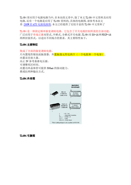
TL494外形图TL494引脚图TL494工作原理简述TL494是一个固定频率的脉冲宽度调制电路,内置了线性锯齿波振荡器,振荡频率可通过外部的一个电阻和一个电容进行调节,其振荡频率如下:输出脉冲的宽度是通过电容CT上的正极性锯齿波电压与另外两个控制信号进行比较来实现。
功率输出管Q1和Q2受控于或非门。
当双稳触发器的时钟信号为低电平时才会被选通,即只有在锯齿波电压大于控制信号期间才会被选通。
当控制信号增大,输出脉冲的宽度将减小。
参见图2。
TL494脉冲控制波形图控制信号由集成电路外部输入,一路送至死区时间比较器,一路送往误差放大器的输入端。
死区时间比较器具有120mV的输入补偿电压,它限制了最小输出死区时间约等于锯齿波周期的4%,当输出端接地,最大输出占空比为96%,而输出端接参考电平时,占空比为48%。
当把死区时间控制输入端接上固定的电压(范围在0—3.3V之间)即能在输出脉冲上产生附加的死区时间。
脉冲宽度调制比较器为误差放大器调节输出脉宽提供了一个手段:当反馈电压从0.5V变化到3.5时,输出的脉冲宽度从被死区确定的最大导通百分比时间中下降到零。
常用光电耦合器参数表

35
6
0.2
18/18
5.3 kV
H11A817D
FSC
300
600
35
6
0.2
18/18
5.3kV
4 脚,光电耦合器 (4 Pin Optocouplers)----GaAs 输入,光电晶体管输出
Part
Number
厂牌
CTR @
10 mA IF(%)
BVCEO
(V)
min
BVCBO
(V)
min
--
--
5.3 kV
MOC8111
20
--
30
7
20/20
5.3 kV
MOC8112
50
--
30
7
20/20
5.3 kV
MOC8113
100
--
30
7
20/20
5.3 kV
SL5582.W
40
320
50
7
20/50
3.75kV
6 脚,光电耦合器 (6 Pin Optocouplers)---GaAs 输入,高电压光电晶体管输出
50
150
35
6
0.2
4/18
5.0kV
H11AA814
Fairchild
20
300
35
6
0.2
--
5.3 kV
H11AA814A
FAIRCHILD
50
150
35
6
0.2
--
5.3 kV
LTV814A
LITEON
50
150
35
4EE-02中文资料

1• 15W Isolated Output • Remote ON/OFF Control • 4:1 Input Range • Efficiency to 82% • Six-Sided Shield • 200KHz Switching FrequencyNOTE: 1.Nominal Input Voltage 24 or 48 VDCMODEL INPUT OUTPUT OUTPUT INPUT CURRENT % EFF.CASENUMBER VOLTAGE VOLTAGE CURRENT NO LOAD FULL LOAD 4EE-014EE-024EE-034EE-044EE-054EE-064EE-074EE-084EE-114EE-124EE-134EE-144EE-154EE-164EE-174EE-189-36 VDC18-72 VDC5 VDC 12 VDC 15 VDC±12 VDC ±15 VDC 5/±12 VDC 5/±15 VDC +5/+12/-5 VDC5 VDC 12 VDC 15 VDC±12 VDC ±15 VDC 5/±12 VDC 5/±15 VDC +5/+12/-5 VDC3000 mA 1250 mA 1000 mA ±625 mA ±500 mA 1500/±310 mA 1500/±250 mA 1500/310/500 mA3000 mA 1250 mA 1000 mA ±625 mA ±500 mA 1500/±310 mA 1500/±250 mA 1500/310/500 mA15 mA 15 mA 15 mA 20 mA 20 mA 20 mA 20 mA 20 mA 10 mA 10 mA 10 mA 15 mA 15 mA 15 mA 15 mA 15 mA810 mA 780 mA 780 mA 780 mA 780 mA 780 mA 780 mA 715 mA 410 mA 390 mA 390 mA 380 mA 380 mA 380 mA 380 mA 350 mA77808080808080807780808282828282EEBEHLMAN2Specifications4E EAll Specifications Typical At Nominal Line,Full Load and 25˚C Unless Otherwise Noted.INPUT SPECIFICATIONS:Input Voltage Range.........................................................................................................................................................24V ....................................................9-36V48V ...................................................18-72VInput Filter....................................................................................................................................................................................................................................Pi TypeOUTPUT SPECIFICATIONS:Voltage AccuracySingle Output........................................................................................................................................................................................................................±1.0% max.Dual +Output........................................................................................................................................................................................................................±1.0% max.-Output........................................................................................................................................................................................................................±3.0% max.Triple,5V .................................................................................................................................................................................................................................±2.0% max.12V/15V .......................................................................................................................................................................................................................±3.0% max.Voltage Balance (Dual).......................................................................................................................................................................................................±1.0% max.Transient Response:Single,25% Step Load Change...........................................................................................................................................................................................<500µsec.Dual,FL-1/2L±1% Error Band.................................................................................................................................................................................................<500µsec.External Trim Adj.Range...............................................................................................................................................................................................................±10%.Ripple & Noise,20MHz BW.........................................................................................................................................................................................10mV RMS,max.75mV p-p max.Temperature Coefficient.....................................................................................................................................................................................................±0.02%/°C Short Circuit Protection......................................................................................................................................................................................................Continuous Line Regulation 1,Single/Dual.............................................................................................................................................................................................±0.2% max.Triple...................................................................................................................................................................................................±1.0% max.Load Regulation 2,Single/Dual...........................................................................................................................................................................................±1.0% max.Triple..................................................................................................................................................................................................±5.0% max.GENERAL SPECIFICATIONS:Efficiency .........................................................................................See Table Isolation Voltage.......................................................................500 VDC min Isolation Resistance.........................................................................109ohms Switching Frequency ..................................................................200KHz,min Operating Temperature Range.........................................-25°C to + 71°C Case Temperature.....................................................................100˚C max.Cooling..........................................................................Free-Air Convection Storage Temperature Range...........................................-55°C to + 105°C EMI/RFI..............................................................Six-Sided Continuous Shield Dimensions...............................................................2.56 x 3.0 x 0.83 inches(65 x 76.2 x 21.1 mm)Case Material................................................Black Coated Copper withNon-Conductive BaseCASE EAll Dimensions In Inches(mm)NOTE:1.Measured From High Line to Low Line2.Measured From Full Load to 1/4 LoadRemote On/Off ControlLogic Compatibility EC-On EC-OffShutdown Idle Current Input Resistance Control Common CMOS or Open Collector TTL >+5.5VDC or Open Circuit<1.8 VDC 10 mA100K ohms (Ein 0 VDC to 9 VDC)Referenced to Input MinusExternal Output TrimmingOutput may optionally be externally trimmed (±10%) with a fixed resistor or an external trimpot as shown.PIN 4PIN 6RT 1OR RT 210K ohms TRIMPOTTRIM DOWNPIN 7PIN 4TRIM UPPIN 6PIN 7PIN 4PIN CONNECTIONPin Single Output Daul Output Triple Output 1.2.3.4.5.6.7.8.+Input-InputNo PinOutput TrimNo Pin+Output-Output+Input -Input +Output Common -Output No Pin No Pin +Input -Input +Output Common -Output +5V Output No PinRemote On/Off ControlTRIPLE OUTPUT LOADING TABLE (1)AmperesMin.(2) Nom.Output Voltage( Pin No.)63 & 53 & 53 & 5+5+12 or -12+15 or -15+12 & -50.250.100.100.10/0.101.50.310.250.31/0.50NOTE:1.Maximum total power from all outputs is limited to 15 watts but no output should be allowed to exceed its maximum current.2.Minimum current on each output is required to maintain specified regulation.BEHLMAN4532 Telephone Road Suite 103 Ventura, CA 93003 80 Cabot Court Hauppauge, NY 11788(805 ) 642-0660 (800)456-2006 Fax (805) 642-0790 e-mail: sales@ (631)435-0410 (800)874-6727 Fax(631)951-4341Web-site: 。
电缆型号详解

电缆型号详解
1、◆ 铜芯塑料绝缘耐火电力电缆 3、◆ 隔火层阻燃电力电缆 5、◆ 辐照交联聚烯烃绝缘电力电缆 7、◆ 交联聚乙烯绝缘无卤低烟阻燃电力电缆 9、◆ 聚氯乙烯绝缘电力电缆 11、◆ 船用控制电缆 13、◆ 舰船用电力电缆 15、◆ 舰船用通信电缆 17、◆ 低烟低卤阻燃电力电缆 19、◆ 低烟无卤阻燃控制电缆 21、◆ 辐照交联聚烯烃绝缘控制电缆 23、◆ 本安型防暴控制电缆
燃性能有高要求的重要场合。
型 号及 名 称
铜芯
型号
铝芯
名称
GZR-W
GZR-VLV
聚氯乙烯绝缘聚氯乙烯护套隔火层阻燃电力电缆
GZR-YJV
GZR-YJLV
交联聚乙烯绝缘聚氯乙烯护套隔火层阻燃电力电缆
GZR-VV22
GZR-VLV22
聚氯乙烯绝缘钢带铠装聚氯乙烯护套隔火层阻燃电力电缆
GZR-YJV22
电气性能
(1) 导体直流电阻参照聚氯乙烯绝缘及护套电力电缆。 (2) 绝缘电阻见表
序号
性能
聚氯乙烯绝缘
交联聚乙烯绝缘
体积电阻率 r W.cm
1
20℃
在电缆工作温度时
1013 1010
1012
绝缘电阻常数 M W.km
2
20℃
在电缆工作温度时
36.7 0.037
3.67
(3) 交流电压试验 成品电缆经受交流 50Hz、5min、3500V 的电压试验不击穿,对于单芯电缆,则进行浸水耐压试验。
用 途:普遍适用于 125℃及以下辐照交联聚烯烃绝缘,且能够阻燃要求的,额定电压 0.6/1KV 及以下的电力系统。 主 要 特 点:
1 电性能较高 由于辐照交联材料内无需添加会导致电性能变差的交联剂,因而体积电阻系数比化学交联高 1~2 个数量级,击穿电场强
黄石科威24V新型EC、EP说明书
AI6+、AI6-:6#通道模拟量输入端子,接热电偶、标准信号、PT100 信号。 AI7+、AI7-:7#通道模拟量输入端子,接热电偶、标准信号、PT100 信号。 AI8+、AI8-:8#通道模拟量输入端子,接热电偶、标准信号、PT100 信号。 AI9+、AI9-:9#通道模拟量输入端子,接热电偶、标准信号、PT100 信号。 CANH、CANL:CAN 网络接口端子。 A、B : RS485 网络端子 A+、B-,固化 CAN 网络配置、组建 RS485 网络。固化 CAN 网络配置时要另配 485/232 转换器。 RS0:编程口,为 232 接口,配专用通讯电缆,下载程序、与人机界面连接。 拨码开关:运行控制端子,拨动拨码开关,可编程控制器处于 RUN 或 STOP 状态。
壁挂式垂直安装
4
★ 接地方式 专用接地(最好) 共用接地(可) 公共接地(不可)
1.2 外形结构尺寸
产品型号
L(mm) 产品型号
L(mm)
EC/P-08M08R-24 100
EP-10H-24
100
EC/P-08M08T-24 100
EP-32M-24
140
EP-10E-24
100
EP-32T-24
使用注意事项
● 可编程控制器的安装位置尽量远离高电压、强电流、高频率等对周围有较强干扰的设备。 ● 请一定在可编程控制器外部组成紧急停电电路,制止正反动作同时进行的连锁电路、上下限定位连锁电路。 ● EC/EP 系列可编程控制器指令集有 86 条指令,如果程序中含有超出这 86 条指令范围的指令,可编程控制器运行时会出错。 ● 在下载梯形图或固化 CANSET 时,下载完毕后,将拨码开关拨到 RUN,等可编程控制器运行后,才能断电,否则,程序得不到固化。 ● 对于变更运行中的程序、强制输出、RUN、STOP 等操作,必须熟读使用手册,充分确认其安全之后进行。
东芝V系列PLC

•Distance
•Speed • Transmission •Scan Transmission
Max 2 km (Between Nodes) / Max 8 Km
100Mbps / 10Mbps 1) Scan Transmission (Common Memory) 2) Message Transmission (TCP/IP, UDP/IP) High Speed Middle Speed Low Speed 1~160 ms (100Mbps) 10~1,000 ms 100~10,000 ms
Integrated Controller V series
Model 3000
Model 1000
Model 2000
1
Features of Integrated Controller
• Adapting IEC language (IEC61131-3 (LD,SFC,FBD,ST,IL))
・TC-Net100 … Time Critical Application (100 Mbps) Metal Industries, General purpose, etc.
・DeviceNet … FA Device Open Network ・TL-S20 … PLC/PLC Communication, TMEIC Drive
High Speed Scan Task : 128 Main Scan Task : 256
IO : 20,000 points
3
Performance of S3
Ladder
r R PCS6000 s R g 0.45 0.04 0.22 1.00 0.02 0.03 1.00 0.20 0.40 0.60 0.80 1.00 1.20 0.20 1.00
E-VAC系列中等电压真空断路器产品说明说明书

Ideal contact material and geometry ensure lowchopping current and reliable contact resistanceA few components and compact and reasonable structure ensure morereliable and safer operation Enable ideal cutoff and close of resistance, inductance load and capacitive loadSecondary plug, chassis, moving contact and grounding methods are specially designed ,completely compatible with domestically dominantmedium voltage switchgearProduct modelsE-VAC vacuum circuit breaker120E-VAC(R)i40/3150-210Voltage ratingsE: IEC/GB standardEaton circuit breaker seriesR indicates fixed type,none indicates drawout typei indicates solid-envelope d pole, none indicates assembled polerated short circuit breaking current ratedcurrentphase spacing1E-VAC series medium voltage vacuum circuit breakerProduct descriptionContentsDescription Page 156810E-VAC series medium voltage vacuum circuit breakerProduct description .................................................................Technical data ..........................................................................Dimensions .............................................................................Wiring diagram ........................................................................E-VAC series vacuum circuit breaker selection table ..............E-VAC vacuum circuit breakerProduct descriptionE-VAC Series medium voltage vacuum circuit breakers from Eaton Electrical combine our excellent vacuum technology with decades of experience in designing and manufacturing power distribution system. They offer high reliability, ease of handling and maintenance, high cost efficiency for different customers.Meet IEC, GB and DL standardsE-VAC equipped with new generation vacuum interrupter, suited fortechnologies and operation condition of power system••••••Technical featuresE-VAC utilizes mature spring operating mechanism, offers reliable and stableperformance, long service life, ease of operating,excellent corrosion protection and low maintenance within the lifetimeE-VAC adopts vertical epoxy insulation cover which can prevent harsh environment influence, making E-VAC circuit breaker suitable for various applications. Unique contact material and primary plum-shaped moving contact make E-VAC suitable for medium voltage system in various applications.E2 level electrical life extended and M2 levelmechanical life extended as per standard, capacitivecurrent breaking and making having extremelylowre-breakdown probability C2 level, having completed the type testAll products have been subject to hundreds of mechanical operation running-in tests beforeleaving the factory, ensuring the product performance in the most stable phase Utilize advanced imported testing equipment, exactly record no-load mechanical characteristics of each product, and provide users with these characteristic curves, ensure product reliability2Application conditionAmbient air temperature not exceeding 40℃, and the average value measured within 24 hours not exceeding 35℃. The minimum ambient air temperature is -15℃The effect by solar radiation can be ignoredThe ambient air is notobviously polluted by dust, smoke, corrosive orflammable gases, vapor or salt mistSeismic intensity not exceeding 8 degreeAmplitude of electromagnetic interference induced in secondary system not exceeding 1.6kV•••••••Outline dimension anddistribution panel interlocking method completelycompatible with domestically dominant medium voltage switchgear, high universality, significantly reduce design costProduct assembly utilizes tooling method to ensure dimension consistency. All products have been subject to the push panel test for standard panel, ensuringproduct interchangeability and universality•••••As the manufacturer of theworld’s first vacuum interrupter, the pioneer of vacuumtechnology, Eaton Electrical has been committed to the research, development and manufacturing of vacuum interrupters for over 70 years, and gathered plenty ofexperience. Westinghouse has become the synonym of quality and reliability.We own the world’s largest and globally leading vacuuminterrupter plant and the only vacuum interrupter plant that is equipped with large capacity high voltage laboratories.Our manufacturing capacity and design and development always maintain a leadership position.Application areasTechnology creation historyOptional accessoriesCharging handle Trolley handleLifterE-VAC series medium voltage vacuum circuit breakerProduct descriptionChemical industry Oil industry Piping industry Offshore mining ShipbuildingPaper making industry Opencast coal mine SubstationCement industry Automotive industry Power plantTextile and food industries Metallurgical industry•••••••••••••Temperature conditionThe average of relativehumidity measured within 24 hours not exceeding 95%The average vapor pressure measured within 24 hours not exceeding 2.2kPaThe average of relative humidity measured within one month not exceeding 90%The average vapor pressure measured within one month not exceeding 1.8kPa••••3E-VAC vacuum circuit breaker requires almost no relevant maintenanceIdeal for control and protection in medium voltage power supply and distribution systemSimple structure design of E-VAC vacuum circuit breaker further minimizes faultoccurrence, simplifies daily maintenance. With theindicator on the circuit breaker panel, no detection instrument is required, facilitating the judgment of working state of circuit breaker.The circuit breaker utilizes the world’s first class EatonElectrical’s vacuum interrupter with vacuum degree up to 10-6Pa, low air leakage, and ensure 50-year life with no maintenance required.The circuit breaker is equipped with superior spring charging mechanism, utilizes modular design, offering optimized mechanism main partdistribution, simpler structure and more reliable performance. The whole mechanism is composed by three modules: charging, closing, opening. Assembly and maintenance of these three parts are very simple. The spring charging mechanism composed by ratchet wheel mechanism,oscillator and closing spring is compact and smart. Theoperating mechanism is usually equipped with manual charging device and electric charging device, enabling automatic reclosing function.The circuit for manual charging operating mechanism isprovided with manual opening and closing operation buttons, circuit breaker position indicator and spring mechanism charging status indicator, switch operations counter, shunt release auxiliary switch, position and fault signals, etc..The circuit breaker of electric charging operating mechanism: added with spring charging motor, shunt release, trip free relay, and auxiliary switch for spring charging motor release.The following accessories can also be provided as needed: undervoltage release,overcurrent relay, etc..E-VAC series medium voltage vacuum circuit breakerProduct description4Main specification and technical parametersItem Unit Value Technical parameters for trip/close coilsNameParameter Note: (1)forced air cooling is required at 4000A; (2) If the user has special requirements, up to 125kA.O-0.3s-CO-180s-CO, O-180s-CO-180s-CO(50kA)5Technical dataE-VAC series medium voltage vacuum circuit breakerT echnical dataRated operating sequenceCharging duration Rated power of spring charging motor Rated voltage of spring charging motor Rated opening operating voltage Rated closing operating voltage Allowable accumulated wearingthickness of moving/fixed contact Rated short circuit current breaking cycleRated current breaking cycleMechanical lifeClosing time Opening time Secondary circuit power frequency withstand voltage (1 min)Rated short circuit making currentRated peak withstand current Rated currentRated frequency Rated lightning impulse withstand voltage (peak)Rated short-time power frequency withstand voltage (1 min)Rated voltageRated short-circuit breaking current Rated short-time withstand current (4s)Hz A kVkA kA kA kA V ms ms Cycle Cycle Cycle mm V V W s1242(phase to ground, phase to phase) 48 (gap)75 (phase to ground, phase to phase) 85(gap)506301250630 12501600 20001250 16002000 25003150 4000(1)1250 16002000 25003150 4000(1)252531.531.54040505063638080100(2)100(2)125130200020~5035~7020000, (10000 cycles at 50kA)20000, (10000 cycles at 50kA)E2(274)3AC 110/220AC 110/22065, (80W at 50kA)≤15DC 110/220V AC 110/220 DC 110/220DC 110/220Normal working voltage rangeRated working voltage (V)Rated working current of close coil (A)Rated working current of trip coil (A)AC, DC110AC, DC2202.0 1.01.80.9Closing: 80%~110% of rated working voltageOpening: 65%~120% of rated working voltage, opening will not occur when the normal working voltage is less than 30% of rated working voltageOutline and dimension of E-VAC circuit breaker (drawout type)Rated short circuit breaking current (kA)Rated current (A)Distribution panelwidth(mm)W S R N M L K J G F E D C B A H P T 6E-VAC series medium voltage vacuum circuit breakerDimensionsDimensions80080080080010001000100010001000630125016001250630125016001600~20002500~400020~31.520~4031.540(Short-circuit 125)20~31.520~4031.531.5~5031.5~50210210210275275275275275275275275275310275275275310310638638638638838838838838838652652652652852852852852852640640640640838838838838838650650650650850850850850850433433433361433433433361361626626626680626626626680680354955793549557910928028028029528028028029529559859859858659859859858658676767677767676777778787888787878888863763763769863763763769869850850850853650850850853653627727727727737737737737737740404004040400023232319313131313180010001000630~1600630~16001600~4000275275210310275275650720520720720520770770588632580580786590IIIII I 275275250252237237465455455Outline and dimension of E-VACR circuit breaker (fixed type)Note: during installation, make sure copper busbar reliably contacts the conductive surface of circuit breaker outlet in free state. Do not exert external force on the copper busbar to adjust its shape. Forced installation is not allowed!Distribution panel width Rated current (A)P H A B C E F G1\G2I J K 7E-VAC series medium voltage vacuum circuit breakerDimensionsE-VAC series medium voltage vacuum circuit breakerWiring diagramWiring diagramSecondary control connection diagram of E-VAC series vacuum circuit breaker (drawout type)The diagram shows the circuit breaker in test position, opening, discharged states8E-VAC series medium voltage vacuum circuit breakerWiring diagramSecondary control connection diagram of E-VACR series vacuum circuit breaker (fixed type) The diagram shows the circuit breaker in opening, discharged states9E-VAC series vacuum circuit breaker selection table1. Circuit breaker models2. Parameters of E-VAC series vacuum circuit breaker3. Technical parameters of spring operating mechanism4. Optional configuration (Standard option includes trip free device. Please note if the trip free device has to been canceled)E-VAC (drawout type)□E-VACR (fixed t ype)□Note: Technical parameters of products will be changed without notice. Please confirm with Eaton Corporation before ordering.10E-VAC series medium voltage vacuum circuit breakerE-VAC series vacuum circuit breaker selection tableParameters NameParameters NameName800Panel width(mm)Breaker phase spacing(mm)Rated short circuit breaking current (kA)(kA)Rated working current (A)21010002752531.540(Short-circuit 100kA )40(Short-circuit 125kA )31.54050□630□630□1250□1250□1250□1250□1600□1600□2000□1600□2000□2500□1600□2000□2500□3150□4000*□3150□4000** Forced air cooling is required at 4000AOpening power supply (V)Closing power supply (V)Spring charging motor power supply (V)□DC110□DC110□DC110□AC110□AC110□AC110□DC220□DC220□DC220□AC220□AC220□AC220□Overcurrent release □Closing latch □Position latch □Trip free relay □Undervoltage release □Operating handle□2 Overcurrent □3 Overcurrent□A□V □V □V □V□Quantity neededEaton is dedicated to ensuring that reliable, efficient and safe power is available when it’s needed most. With unparalleled knowledge of electrical power management across industries, experts at Eaton deliver customized, integrated solutions to solve our customers’ most critical challenges.Our focus is on delivering the right solution for the application. But, decision makers demand more than just innovative products. They turn to Eaton for an unwavering commitment to personal support that makes customer success a top priority. For more information,visit /seasia-electrical.Electrical Sector Asia PacificNo.3, Lane 280, Linhong Road,Changning District, ShanghaiEaton Industries Pte LtdElectrical Sector4 Loyang Lane #04-01/02Singapore 508914/seasia-electrical© 2013 Eaton Corporation All Rights Reserved Printed in SingaporeJuly 2013Eaton is a registered trademarkof Eaton Corporation.All trademarks are property of their respective owners.。
CS5460A中文数据手册
Cirrus Lohai benhong Electronics Technologies Co.,Ltd Contactee: Zhoubenhong Addr: Rm1101,No 47,Lane 1111,Lianhua South Rd,Shanghai China, P.R.China. 201100
2.综述 ..................................................................................................................................................... 12 2.1 操作原理 ..................................................................................................................................... 12 2.1.1 ÄÓ 调制器 .......................................................................................................................... 12 2.1.2 高速数字低通滤波器......................................................................................................... 12 2.1.3 数字补偿滤波器 ................................................................................................................ 12 2.1.4 数字高通滤波器 ................................................................................................................ 12 2.1.5 总的滤波器响应 ................................................................................................................ 12 2.1.6 增益及 DC 偏移量调整 ..................................................................................................... 12 2.1.7 有功能量及有效值计算 ..................................................................................................... 13 2.2 执行测量 ..................................................................................................................................... 13 2.2.1 CS5460A 线性性能 ........................................................................................................... 14 2.2.2 单计算周期(C=0 ) ....................................................................................................... 14 2.2.3 连续计算周期(C=1 ).................................................................................................... 15 2.3 基本应用电路结构....................................................................................................................... 15
- 1、下载文档前请自行甄别文档内容的完整性,平台不提供额外的编辑、内容补充、找答案等附加服务。
- 2、"仅部分预览"的文档,不可在线预览部分如存在完整性等问题,可反馈申请退款(可完整预览的文档不适用该条件!)。
- 3、如文档侵犯您的权益,请联系客服反馈,我们会尽快为您处理(人工客服工作时间:9:00-18:30)。
2SC4964
Silicon NPN Epitaxial
REJ03G0736-0300 (Previous ADE-208-005A)
Rev.3.00 Aug.10.2005
Application
VHF / UHF RF switch
Features
• Low Ron and high performance for RF switch. • Capable of high density mounting.
Outline
RENESAS Package code: PLSP0003ZB-A (Package name: MPAK)
12
3
1. Emitter
2. Base
3. Collector
Marking is “YV–”.
Absolute Maximum Ratings
(Ta = 25°C)
Item Symbol Ratings Unit
Collector to base voltage V CBO 12 V Collector to emitter voltage V CEO 8 V Emitter to base voltage V EBO 3 V Collector current I C 100 mA Collector power dissipation P C 150 mW Junction temperature Tj 150 °C Storage temperature Tstg –55 to +150 °C
Electrical Characteristics
(Ta = 25°C)
Test
conditions
Unit
Typ
Item Symbol
Min
Max
Collector to base breakdown voltage V(BR)CBO 12 — — V I C = 10 µA, I E = 0
Collector cutoff current I CBO — — 1 µA V CB = 10 V, I E = 0
V CE = 8 V, R BE = ∞
I CEO — — 1 mA
Emitter cutoff current I EBO — — 10 µA V EB = 3 V, I C = 0
DC current transfer ratio h FE 100 250 600 V CE = 5 V, I C = 5 mA
I C = 80 mA, I B = 5 mA
Collector to emitter saturation voltage V CE(sat) — 200 300 mV
Collector output capacitance Cob — 1.2 1.6 pF V CB = 5 V, I E = 0, f = 1 MHz
On resistance Ron — 2.0 — ΩI B = 2.5 mA, f = 1 kHz
Main Characteristics
150
10050Ambient Temperature Ta (°C)
Collector Current I C 12510200
1251020Collector to Base Voltage V CB (V)I = 0f = 1 MHz
E
Collector Output Capacitance vs.
Collector to Base Voltage
Collector Current I C 12510202.0
1.61.20.80.4G a i n B a n d w i d t h P r o d u c t f T (G H z )
V = 5V Gain Bandwidth Product vs.
Collector Current
f = 1kHz
On Resistance vs. Base Current
Vin
100µF R1(1k )Ω
100Ron test circuit
100
200
500
1000
Frequency f (MHz)
V = 5V B
V = 0B
INPUT 33pF
33pF 2nF
L2
V B
D.U.T.
L1 , L2 : Inside dia φ 3 mm ,
φ 0.5 mm Enameled Copper Wire 7 Turns.
L1
2.7k Ω
Package Dimensions
b
x S
A
M A
A 2
A 1
S
b A-A Section
b 1
c 1Pattern of terminal position areas
I 1
b 2
e
e 1
A A 1A 2A 3b b 1c c 1D E e H E L L 1L P x b 2e 1I 1Q
Ordering Information
Part Name Quantity
Shipping Container
2SC4964YV-TL-E 3000
φ 178 mm Reel, 8 mm Emboss Taping
Note: For some grades, production may be terminated. Please contact the Renesas sales office to check the state of
production before ordering the product.
RENESAS SALES OFFICES
Refer to "/en/network" for the latest and detailed information.
Renesas Technology America, Inc.
450 Holger Way, San Jose, CA 95134-1368, U.S.A
Tel: <1> (408) 382-7500, Fax: <1> (408) 382-7501
Renesas Technology Europe Limited
Dukes Meadow, Millboard Road, Bourne End, Buckinghamshire, SL8 5FH, U.K.
Tel: <44> (1628) 585-100, Fax: <44> (1628) 585-900
Renesas Technology Hong Kong Ltd.
7th Floor, North Tower, World Finance Centre, Harbour City, 1 Canton Road, Tsimshatsui, Kowloon, Hong Kong
Tel: <852> 2265-6688, Fax: <852> 2730-6071
Renesas Technology Taiwan Co., Ltd.
10th Floor, No.99, Fushing North Road, Taipei, Taiwan
Tel: <886> (2) 2715-2888, Fax: <886> (2) 2713-2999
Renesas Technology (Shanghai) Co., Ltd.
Unit2607 Ruijing Building, No.205 Maoming Road (S), Shanghai 200020, China
Tel: <86> (21) 6472-1001, Fax: <86> (21) 6415-2952
Renesas Technology Singapore Pte. Ltd.
1 Harbour Front Avenue, #06-10, Keppel Bay Tower, Singapore 098632
Tel: <65> 6213-0200, Fax: <65> 6278-8001
Renesas Technology Korea Co., Ltd.
Kukje Center Bldg. 18th Fl., 191, 2-ka, Hangang-ro, Yongsan-ku, Seoul 140-702, Korea
Tel: <82> 2-796-3115, Fax: <82> 2-796-2145
Renesas Technology Malaysia Sdn. Bhd.
Unit 906, Block B, Menara Amcorp, Amcorp Trade Centre, No.18, Jalan Persiaran Barat, 46050 Petaling Jaya, Selangor Darul Ehsan, Malaysia
Tel: <603> 7955-9390, Fax: <603> 7955-9510。