KFD阀门控制箱中英文说明书
电动阀门执行器出口英文使用说明书
Non-Invasive Electric Actuator Electronic control module debugginginstructionsVersion V201SummaryThis component can receive the DCS system on-off signals (passive dry contact of active, active 24 v, 220 v, keep running can switch) or analog signals (DC4-20 ma, 0 to 10 v, etc.), direct drive electric actuators switch action or adjust the action. Output DC4-20 ma feedback current and contact/remote control state instructions. The component integration the servo control unit, solid-state drive unit, liquid crystal display unit, knobs and other ancillary units and aluminum shell assembly operation.The product operates as a fool camera is simple, like intelligent perfect protection function.2Operating Instructions2.1Knob Operating InstructionsThe red knob is the mode button, can be switched between Local/Stop/Remote. Or in a set state, to save the menu contents (from the stop bit screwed to the site) or to exit the menu(from the stop bit screwed into the remote).Black knob for the operating button can be opened or closed operation at the local.Or to plus or minus in the set state.With button operation, short time effect for the inching mode. When the operation button is effective for more than 3 seconds, in the lower right corner of the LCD, the bc is displayed automatically entered into the hold mode. When actuator movement, click the action button reverse rotation or spin mode button to Stop, the actuator Array stops.2.2 setting tool description (setting tool are optional, needto please when ordering special instructions)"Up" button = Open calibration key, "Down" button = close calibrationkey, "Enter" button = Confirm key or Save key"Stop" button = stop key, "Open" button = open key, "Close" button =close key.When mode button at Local location, press "Open" button to performopen, press "Close" button to perform off. In the action, press the"Stop" button to stop the move, short press "Close" to stop the openingprocess, short press "Open" to stop the closing process.In local mode, even by three "Up" key to enter the open position calibration status, "Open", "Close" and "Stop" keys to control the electric actuator to open, close and stop, "Enter" key to save the trip, "Stop "key is used to return.In local mode, even by three "Down" key to enter the closed position calibration status, like the rest of the operation as above.3Signal query (LCD lower left corner for a signal check area) 3.1 Remote control signal inquiryWhen the mode button is screwed into the Remote, the remote control signal received is displayed in the lower-left corner of the LCD. Switch type: show OP represents a open signal, show CL represents a close signal, show BC represents a keep signal (multi state of coexistence of alternate display). Regulating type: to display the received control current value or voltage value.3.2 Valve position signal queryWhen the mode button is screwed onto the Local, the LCD shows the valve position signal in lower left corner. When using a potentiometer, show the percentage of resistance (d01 ~ d99); When using 12 encoder, shows the percentage of the encoder (b01 ~ b99); When using 18 encoder, display micrometer ratio of the encoder (001 to 999).4 4 Stroke calibrations4.1 Calibration for close limit:The mode button at the Stop position, the rotary operation knob to the Close position for about 3 seconds, until the letter L is flashing of the LCD to release operation button, then the mode button to the Local position, now letter L no longer flashes and the system into the closed position calibration status. The actuator can open or close by the operating button. When the actuator operates to the closed position, then the mode button to spin the Stop position, and back to the Local position, at this time the red LED flashing two times said the closed position calibration is completed. If the mode button is screwed to the Remote position from Stop position, that exit travel calibration.4.2 Calibration for open limitThe mode button at the Stop position, the rotary operation knob to the Open position for about 3 seconds, until the letter H is flashing of the LCD to release operation button, then the mode button to the Local position, now letter H no longer flashes and the system into the open position calibration status. The actuator can open or close by the operatingmode button to spin the Stop position, and back to the Local position, at this time the green LED flashing two times said the open limit position calibration is completed. If the mode button is screwed to the Remote position from Stop position, that exit travel calibration.Note: When you save a stroke, display Fu or Fn characters on the LCD, please re-adjust potentiometer or rotary encoder range, and recalibrate the trip.5Feedback current trimming5.1 Feedback current 4mA trimmingThe mode button at the Stop position, the rotary operation knob to the Open position for about 10 seconds, until the letter LF is flashing of the LCD to release operation button, then the mode button to the Local position and back to the Stop position, and the system into the 4mA current trimming status. At this point,the size of the output current can be adjusted by the operating button. When adjusting the output current reaches 4mA, then mode button to spin the Local position, this time the red LED flashes three times, said 4mA output current trim is complete. If the mode button to Stop position from Remote position, which exit status of the output current trim.5.2 Feedback current 20mA trimmingThe mode button at the Stop position, the rotary operation knob to the Open position for about 10 seconds, until the letter HF is flashing of the LCD to release operation button, then the mode button to the Local position and back to the Stop position, and the system into the 20mA current trimming status. At this point,the size of the output current can be adjusted by the operating button. When adjusting the output current reaches 4mA, then mode button to spin the Local position, this time the green LED flashes three times, said 20mA output current trim is complete. If the mode button to Stop position from Remote position, which exit status of the output current trim.6About dead zoneThe dead zone to adapt automatically, without setting can ensure that in any conditions without oscillation, and the positioning precision is higher.7Alarm description (error code displayed on the LCD in the lower right corner) FaultcodeFault informationFA Actuator running direction errorFu V alve position potentiometer or encoder Angle is too largeFn V alve position potentiometer or encoder Angle is too smallFP Power phaseFF Broken valve position potentiometer, rotary to blind or pick the wrong line, or encoder failure.FC Over closed torqueFO Over open torqueFH Remote control signals to open and close signals exist (only on-off type)FS Control current signal is lost (only positioning)Fb Current control signal calibration error(only positioning)Fd Stall or other causes the valve position does not changeFL Limit contact line or torque contact line reversedFE The motor is too hot or the torque public terminal is openNOTE: The green LED is the open limit position light on the screen, the red LED is closed position light on the screen.8Advanced SettingsNOTE: All the Advanced Settings can be set after the mode button in the "Local" position. Advanced settings must open the electrical box cover and you can operate. The Close Key and Open Key mentioned below are in the electronic control board.8.1 Action when the control current loss:(Only positioning type, default: Remain in Situ)8.1.1 To press the “Close Key” and power up for 3 seconds until the red LED on the board is lit. And you release the key, then the red LED flashes three times; the “FullClose” setup is completed.8.1.2 To press the “Open Key” and power up for 3 seconds until the green LED on the board is lit. And you release the key, then the green LED flashes three times; the “Full Open” setup is completed.8.1.3 Simultaneously press two keys and power up for 3 seconds until the green and red LEDs on the board are lit. And you release the two keys simultaneously, then the two LEDs flashes three times; the “Remain in Situ” setup is completed.8.2 Control current calibration:(Only positioning type)8.2.1 To send 4mA control current to the module from the outside, press the “Close Key” and power up for 10 seconds until the red LED on the board is lighted second times. And you release the key, then the red LED flashes three times; and the4mA calibration is completed.8.2.2 To send 20mA control current to the module from the outside, press the “Open Key” and power up for 10 seconds until the green LED on the board is lighted second times. And you release the key, then the green LED flashes three times; and the20mA calibration is completed.8.3 Polarity for the control current:(Only positioning type)20mA = Full Open /4mA = Full Open (default:20mA = Full Open) Simultaneously press “Open Key” and “Close Key” and then power up for 10 seconds. To release the key after the red LED and green LED second lights up. Short press “Open Key” or “Close Key” to alternately lit red LED or green LED. The red LED light represents “20mA = Full Open”, the green LED light represents “4mA = Full Open”. Simultaneously press “Open Key” and “Close Key” for 3 seconds. To release two keys after the two LEDs lights up. Then corresponding LED flashes three times, the polarity for the control current setup is complete.8.4 Two-Wire Control:(Only on-off type)Disable or Open First or Close First (default: Disable)8.4.1Close FirstYou press “Close Key” and then power up for 10 seconds. The key is released after the red LED second light up. And the red LED flashes three times, this setup is complete. This Close First refers to the actuator close operation when voltages signal on the “Remote Close” terminal of the actuator. But no voltage signal, actuators open operation. When wiring, “Remote Open” terminal connected to 24V +.8.4.2Open FirstYou press the “Open Key” and then power up for 10 seconds. The key is released after the green LED second light up. And the green LED flashes three times, this setup is complete.This Open First refers to the actuator open operation when voltages signal on the “Remote Open” terminal of the actuator. But no voltage signal, actuators close operation. When wiring, “Remote Close” terminal connected to 24V +.8.4.3 DisableYou press the two keys simultaneously and then power up for 10 seconds. The key is released after the two LEDs second lights up. Then the two LEDs flashes three times, this setup is complete.8.5 Close direction:Clockwise /Anti-clockwise (default:Clockwise)You press the “Open Key” and “Close Key” simultaneously and then power up for 20 seconds. The keys are released after the red LED and green LED third lights up. Short press “Open Key” or “Close Key” to alternately lit red LED or green LED. Red LED light represents “Clockwise”, green LED light represents “Anti-clockwise”. You press the two keys simultaneously for 3 seconds. The keys is released after the two LEDs light up. Then corresponding LED flashes three times, the Close direction setup is complete.9Common problems to deal withPower LED is not lit or digital display does not show 1. Power is not actually access. 2. voltage is too low 3. Wiring fault. 4. Module badLEDs and digital display abnormal 1. See fault code.2. Query information.3. Replace the moduleAfter power on ,actuator can be not control in the LOCAL and REMOTE mode 1. Wiring fault or loose wiring. 2. Fault Protection.3. Motor bad or stuck.4. Bad start capacitor.5. module badLOCAL mode work is normal but the REMOTE mode can't control 1. No signal or junction anti- , 2. Bad or no knob plate in Remote3. Positive / reaction set wrong.4. Module badREMOTE mode work is normal but the LOCAL mode can't control 1. Not in LOCAL mode. 2. Knobs board bad or not at the scene mode. 3. Operation button is not properly screwed in placeActuator can open but not close or can close but not open 1. Torque wiring fault or loose wiring. 2. to limit position or over torque3. Motor bad or stall or wiring fault.4. Module badThe action immediately after power on 1. Wiring fault. 2. control signal is present3. Implementation the action when the control current loss4. Set the wrong.5. module badThe middle position can move but to the limit position does not move 1. Reverse limit switch line. 2. Motor bad or loose wiring 3. Module badThe direction of movement is the anti 1. Motor lines reversed. 2. Anti valve calibration.3. Signal Reverse4. Polarity for the control current or closing direction set wrong.No output current or sometimes no 1. The output wiring fault or bad. 2. Module bad 3. potentiometer wiring fault or loose wiringFeedback current is larger or smaller or unchanged 1.Potentiometer failure. 2. Calibration error.3. module bad4. potentiometer meshing with drive gear not wellNote: Please strictly in accordance with the wiring diagram electrical wiring connection.Like has the change, without notice。
电动蝶阀使用说明书中英文
电动蝶阀使用说明书中英文电动蝶阀Electric Butterfly Valve使用说明书Operation Manual一、用途Ⅰ.Application本系列蝶阀适用于冶金、矿山、建材、石化、造纸、纺织等行业的工业管道中。
它对气体半流体等管道中的介质按不同的信号,改变其流量的大小,从而达到自动调整风量,实现自动控制。
体阀采用优质钢板焊接结构,具有传动轻巧灵活,密封性能好,开闭时间短,切断速度快,能可靠的杜绝事故的发生。
This series butterfly valve is suitable to use in the industry pipe of metallurgical, ore building material. Paper textile and so on, Accord to the different signal in the pipes of the gas half fluid medium. Change the flow volume, and adjust the fan volume automatically. It can realize automatic control. The valve is used good welding structure. It is characterized by light, nimble good sealing, short open time, fast speed broken and dependable.二、结构及工作原理Ⅱ.The structure and Working principle1、电动蝶阀由电动执行机构和蝶阀组成,有关电动执行机构作用原理,使用维护等参阅电动执行机构说明书。
1、The electric butterfly valve is composed of electric execute structure and butter fly valve. The relative electric execute. Working principle and main is refer to the operation manual of electric executor.2、电动蝶阀按作业方式可分为电开式和电关式两种。
D型阀门执行头使用说明
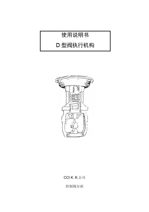
CCI K. K.公司控制阀分部目录D型执行机构的操作 (2)各部件的检查与更换建议 (3)1. 从阀体上(整体)拆卸执行机构的方法 (4)2. 隔膜的检查与维护 (5)3. 执行机构组件的拆卸 (6)4 测试 (7)5. 直接动作到反向动作执行机构的重新组装 (8)D型执行机构的安装I 收到阀门时要注意的事项:1. 检查一下阀体、执行机构和附件,看是否存在运输途中损坏的现象。
2. 在将阀安装到管道上之前,不要去掉保护板或其他保护件。
II 阀门的支撑阀门最好是靠其本体或依靠其邻近的管道来支撑。
执行机构通常不需要支撑,因为它有足够的强度,但当对其提供支撑时,应注意:直动阀(DA):不要固定轭铁,因为它要在行程范围内运动。
反向动作阀(RA):用一个支架支撑执行机构,注意不要固定轭铁、隔膜座和盖,因为它们都将要在全行程内运动。
手轮操作注意事项(1)关于开启与关闭方向,请注意参看铭牌上的旋转方向说明,不要搞错。
(2)操作手轮,同时用阀行程指示器确认阀的开度。
(3)操作之后,将手轮以逆时针方向转到底,保持自动工作方式。
(4)不得用管子或类似的东西来转动手轮。
D 型执行机构的操作—直动操作式—这种D 型执行机构的操作比较独特。
用示意图来表示这种操作,图中用不同的颜色来表示所有运动部件。
左侧的图式,表示的是直动操作。
当隔膜上方的空气压力增加时,阀门的开度减小。
随着空气压力的下降,阀门的开度加大。
操作时,应对整个轭铁部位施加作用力,而不要只将力量作用到阀杆这一小部分区域上。
阀门的定位十分精密。
填料函内的游隙很小,磨损也很小。
阀杆的动作引导得十分精确。
—反向动作式—右侧的图式表示的是反向动作。
隔膜板被固定在框架上。
该框架被固定死而不能移动。
隔膜腔和阀杆均被安装在轭铁上,轭铁可自由活动。
气压通过与直动操作中一样的开口,从隔膜的顶部进入到隔膜腔。
与其它老式设计的反向动作阀门不同的是, 这种阀门,在隔膜的下方不需要设立额外的填料函。
DFK 型电动阀门控制器 说明书
DFK型电动阀门控制器概述DFK型电动阀门控制器(以下简称“控制器”)是与阀门电动装置配套使用的产品,用以控制电动阀门的开启和关闭。
特点1.控制电路采用直流低压控制,调试、操作安全,控制可靠,开度指示准确直观。
2.机壳采用标准的仪表机箱,体积小重量轻,便于安装在控制屏上。
3.指示灯指示开阀、关阀、阀全开、阀全关、事故、保护、现场、远控等状态。
4.提供现场控制可能。
5.电动阀门出力矩(事故)或电机过电流、过热(保护)时报警显示,便于及时排除故障(取决于电动装置的相关功能,不同生产厂家的阀门电动装置,可能不含电动机过热保护)。
技术数据1.工作电压220V / 50Hz控制电压380V / 50Hz2.控制功率小于1.1KW3.环境温度:-20~40℃4.相对湿度:不大于80%(20±5℃时)5.周围不含有强腐蚀性、易燃易爆介质。
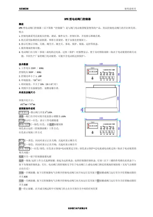
外形及安装尺寸:屏装开孔尺寸:152+1mm×76+1mm前面板部件说明开度显示—指示阀门开度0~100%调整—阀门全开时可将开度表指示调整为100%电源指示灯—红色,表示工作电源接通现场/远控灯—绿色/红色,由选择按键切换绿色表示远控(控制器面板)工作方式;红色表示现场工作方式阀关灯—黄色,闪动时表示正在关阀;亮起时表示阀全关阀开灯—绿色,闪动时表示正在开阀;亮起时表示阀全开事故/保护灯—红色/绿色,红色表示事故-电动装置过力矩;绿色表示保护-过电流或电动机过热(取决于电动装置的相关功能)电源开关—按下控制器接通电源选择—现场/远控工作方式选择按键,抬起为远控状态,也即控制器控制状态,灯绿(以下三键的作用都在此状态下);按下为现场控制状态,灯红,电动阀门的控制权交予位于电动阀门上或电动阀门附近的现场控制按钮(无电气自锁即点动方式)开阀—开阀按键,按下后控制器电气自锁并控制电动阀门向开向运行直至按下停按键或阀门运行至全开位置触动限位开关KXK关阀—关阀按键,按下后控制器电气自锁并控制电动阀门向关向运行直至按下停按键或阀门运行至全关位置触动限位开关GXK停—停止按键,在开或关阀过程中可使阀门停止在全开到全关中间的任何位置后面板部件说明熔断器—控制器工作电源保护,熔芯型号0.5A/Φ5×20A.B.C.N—电源端子AC 380V 50HzPE—保护接地端子U.V.W—电动机接线端子,分别接电动机相应端子1~9—电动装置控制反馈端子,分别接电动装置的相应端子10.11.12—现场开关端子工作原理简述FCHⅡ型控制器的电路主要由控制电路、工作显示电路、开度指示电路和主电路(主电路中的行程和力矩微动开关KXK,GXK,KZK,GZK和电机在阀门电动装置内)四部分组成。
阀门的安装说明书(中英文)
阀门的安装说明书(中英文对照)焊接与银钎焊SOLDERING AND SILVER BRAZING务必记住所推荐的阀门的用途是什么,并对所应用的环境进行分析,这样才能决定选用最适合安装什么样的阀门。
在安装正确的阀门之前,为了防止损坏阀门,并保证充分发挥阀门的工作性能,请阅读一下安装指南:Analyze the application to determine which valve is best suited for installations, keeping in mind the service for which the valve is recommended. Before installing the correct valve, review the installation instructions to prevent damage to the valve and to assure its maximum efficiency:先沿着垂直方向切割管道,并修整、去除毛刺,测量管径。
Cut tube end square. Ream, burr and size.使用纱布或钢丝刷清除管道和切割部位,使其金属表面发光发亮。
建议不要使用钢丝绒。
Use sand cloth or steel wire brush to clean both ends to a bright metal finish. Steel wool is not recommended.在管道的外面和焊接罩的内部涂上焊剂,焊剂必须完全覆盖焊接表面。
请有节制地使用焊剂。
Apply flux to outside of tube and inside of solder cup. Surfaces to be joined must be completely covered. Use flux sparingly.要确保阀门处于开启状态。
中英文对照说明书
中英文对照说明书【篇一:中英文对照说明书】前言preface感谢您使用徐州燃烧控制研究院有限公司生产的就地点火控制柜装置。
本公司的就地点火控制柜装置是徐州燃烧控制研究院有限公司自主开发生产的高品质就地控制装置,在使用系列本程控装置之前请您仔细阅读该手册以保证正确使用并充分发挥其优越性。
本说明书对就地控制柜(以下简称控制柜)的操作和安装方法等做了详细的介绍。
使用控制柜以前,在阅读本说明书的基础上,进行安全正确使用。
thank you for choosing the local ignition control cabinet designed by our company.the local ignition control device is explored by our company for the ignition control of boiler.this manual describes installation and operation of the cabinet clearly, please read this manual before using.内容介绍brief introduction本手册介绍了点火控制柜的组成、安装、配线、功能参数、日常使用维护及对故障的处理the manual includes the cabinet’s components, installation, wiring, data, maintenance, and troubleshooting.读者对象applicable readers本书适合下列人员阅读this manual is applicable for设备安装人员、维护人员、设计人员installer, maintenance man, and designer本书约定stipulation符号约定symbol stipulations说明提醒操作者需重点关注的地方points operator should pay attention to由于没有按要求操作可能造成死亡或重伤的场合危险!this symbol indicates death or gbh that may occur as a result of improper operation由于没有按要求操作可能造成中等程度伤害或轻伤或造成物质损害的场合注意!this symbol indicates secondary injury, flesh wound or object damage that may occur as a result of improper operation一、序言prologue1.1 开箱检查checking在开箱时请认真确认在运输中是否有破损现象控制柜内元器件与附图中的型号数量是否相符如发现有某种遗漏请速与供货商或我司联系解决!check if there is any damage.ensure the model and quantity in chart are accordance with components in cabinet.if there is any mistake, please contact with supplier or ourcompany.1.2 安全注意事项security不要安装在含有爆炸气体的环境里否则有引发爆炸的危险!必须由具有专业资格的人员进行配线作业否则有触电的危险!确认电源处于完全断开的情况下才能进行配线作业否则有触电危险!必须将控制柜的接地端子可靠接地否则有触电的危险!通电情况下不要用手触摸控制端子否则有触电的危险!do not install in explosive environment, or it may causeexplosion.do invite professionals for accompany when wiring, or it may cause electric shockdo shut off power before wiring.do earth the cabinet ground terminal.do not touch the control terminal when power is on.1.3 安装条件installation requirement1.4 日常维护maintenance定期检查柜内各种元器件,确认任一单元都没有松动的螺钉,所有电源和电线的连接都安全可靠;并保持外观完好。
中英文对照说明书
前言Preface感谢您使用徐州燃烧控制研究院有限公司生产的就地点火控制柜装置。
本公司的就地点火控制柜装置是徐州燃烧控制研究院有限公司自主开发生产的高品质就地控制装置,在使用系列本程控装置之前请您仔细阅读该手册以保证正确使用并充分发挥其优越性。
本说明书对就地控制柜(以下简称控制柜)的操作和安装方法等做了详细的介绍。
使用控制柜以前,在阅读本说明书的基础上,进行安全正确使用。
Thank you for choosing the Local Ignition Control Cabinet designed by our company.The local ignition control device is explored by our company for the ignition control of boiler.This manual describes installation and operation of the cabinet clearly, please read this manual before using.内容介绍Brief introduction本手册介绍了点火控制柜的组成、安装、配线、功能参数、日常使用维护及对故障的处理The manual includes the cabinet’s components, installation, wiring, data, maintenance, and troubleshooting.读者对象Applicable readers本书适合下列人员阅读This manual is applicable for设备安装人员、维护人员、设计人员Installer, maintenance man, and designer本书约定Stipulation符号约定Symbol stipulations说明提醒操作者需重点关注的地方Points operator should pay attention to由于没有按要求操作可能造成死亡或重伤的场合危险!This symbol indicates death or GBH that may occur as a resultof improper operation由于没有按要求操作可能造成中等程度伤害或轻伤或造成物质损害的场合注意!This symbol indicates secondary injury, flesh wound or objectdamage that may occur as a result of improper operation一、序言Prologue1.1 开箱检查Checking在开箱时请认真确认在运输中是否有破损现象控制柜内元器件与附图中的型号数量是否相符如发现有某种遗漏请速与供货商或我司联系解决!Check if there is any damage.Ensure the model and quantity in chart are accordance withcomponents in cabinet.If there is any mistake, please contact with supplier or ourcompany.1.2 安全注意事项Security不要安装在含有爆炸气体的环境里否则有引发爆炸的危险!必须由具有专业资格的人员进行配线作业否则有触电的危险!确认电源处于完全断开的情况下才能进行配线作业否则有触电危险!必须将控制柜的接地端子可靠接地否则有触电的危险!通电情况下不要用手触摸控制端子否则有触电的危险!Do not install in explosive environment, or it may causeexplosion.Do invite professionals for accompany when wiring, or it maycause electric shockDo shut off power before wiring.Do earth the cabinet ground terminal.Do not touch the control terminal when power is on.1.3 安装条件Installation Requirement1.4 日常维护Maintenance定期检查柜内各种元器件,确认任一单元都没有松动的螺钉,所有电源和电线的连接都安全可靠;并保持外观完好。
KFD阀门控制箱中英文说明书
额定电流(安培)调节型适用电装型号Ⅲ配型、型Ⅳ配型结构形式:、抽屉式、小型R ated current (am pere)T A djusting typeZ W Q W JQ A pplicable type of electric fitting: for ZW type and Q W type.C X G Structure from : C draw er type, X sm all C ontrol cabinet of electric valve cabinetⅢⅣ抽屉式、挂壁式、、、阀门电动装置控制箱for JQ type draw er type, G wall type K F D —— 普 通 型 KFD 系 列 Common type KFD series一、概 述 Brief introduction该系列电动阀门控制箱,是与我厂生产的ZW 型、JQ 型及QW 型阀门电动装置配套使用的电控箱,用于控制阀门的开启和关闭,可用于现场单独控制或远方集中控制。
KFD 型电控箱有抽屉式和挂壁式两种结构。
This series of control cabinet of electric valve is the one to be used together with ZW type, JQ type and QW type electric valve actuator produced by our company and to control the opening and closing of valve. It can be used in site individual control or long-distance centralized control.KFD type electric control cabinet has two kinds of structure: drawer type and wall type. Designation型号表示方法 Designation二、技术数据 T echnical data1、电源:380V 50Hz 三相四线制(特殊要求,另见)2、工作环境:(1)环境温度:—20℃~+60℃ (2)相对湿度:≤85%(20℃时)(3)周围不含强腐蚀性、易燃易爆介质及导电尘埃。
浦发电子方向控制阀门说明书
Directionalcontrol Valves G1/8, 3/2 and 5/2 Spool valves Catalogue no: 2131GB-caDirectional control valves G1/8 3/2 - 5/2 Spool valves 3/2, 5/2 - G1/8 PortsAvailable in 3/2 or 5/2 versions, all valves including double pilot and double solenoid types may be mounted in any position, The balanced spool design ensures that operating forces remain unaffected by variations in inlet pressure.The body is a zinc alloy die-casting with stainless steel spool, sealed by viton rubber 'O' rings. All operating parts exposed to the working fluid are of non-corrosive material and all ports are threaded G1/8 B.S.P. parallel. The block design of the body with its three mounting holes is ideally suited to close banking and all valves may be serviced without disturbing the pipework simply by unscrewing the actuator and return assemblies.The 3/2 valve can be piped normally open or closed simply by changing the air inlet from the normal inlet port to the exhaust port, and the 5/2 valve can be piped in different variations to suit the application required. Midget spool valves can also be used as impulse type valves, when the signal is required at the end of the cylinder stroke or when the tripping cylinder or machine cam is too small to clear the mechanical trip of the valve.Operation of the actuator on the 5/2 valve opens the cylinder port nearest to the actuator. On the 3/2 version the inlet is piped to the port furthest away from the actuator for normally closed operation, and to the port nearest the actuator for normally open. Any of the actuators may be fitted with spring or pilot return mechanism. Valves may also be supplied with the same actuator at both ends; e.g. double roller. Roller versions are designed to give a common height on both 3/2 and 5/2 valves to ensure uniformity and efficiency in a multi-valve assembly.The reasonably short travel and lightweight spool ensures that extremely high operating speeds are possible. A double pilot 5/2 valve has been tested at over 3000 cycles per minute, but for practical purposes the operating speed of the valve is determined by cylinder stroke and bore size.FeaturesZinc diecastseal spacersIntegral mountingholesStatic Viton 'O' ringsNylon spring housingStainless steelspoolPlastic bushNitrile pilotpiston sealsDirectional control valves G 1/8 3/2 - 5/2Basic body dimensions (mm)Actuator mechanismsReturn mechanismsFacia actuators Ø22mmManual ButtonLock down lever Palm lever FootMechanical Plunger Whisker RollerOne way tripOne way roller tripAir pilotSolenoid pilotBasic bodies 3/2 bodyDirectional control valves G 1/8 3/2 - 5/2Solenoid pilot operated - spring returnSymbolBody Zinc diecast Actuator Zinc diecast Spool Stainless steel Bushes BrassSealsViton (valve body)Nitrile (solenoid)Spring housingPlasticMaterialsPressure range Vacuum to 10 bar Minimum Spring return3 bar Nominal Ø3,2mm Nominal flow at 7 bar 7 dm 3/s Cv factor0,24Pneumatic informationType Spool valve Style Body ported Port size G 1/8MountingAny plane Temperature range-100C to +550CTechnical informationPart nos.Type Actuator Return SymbolLB43313*3/2Solenoid pilot SpringOrdering information*Specify voltage and add suffix lettersFor manual override add suffix M to part no.Power consumptionInrush Hold AC 9VA 6VADC5 WattRating 100% continuous Isolating class FProtection class IP 65 (P 54) DIN 40 050ConnectionISO 4400, BS 56361Electrical informationVoltage selectionSuffix 50 Hz D.C.T 10-135-6.5TA 20-2610-13TF 44-5520-26TC 85-11044-55S 94-12047-60TS 153-19876-99SA204-264102-132Directional control valves G1/8 3/2 - 5/2 3/2 valve dimensions (mm)5/2 valve dimensions (mm)Directional control valves G 1/8 3/2 - 5/2Solenoid pilot operated - pilot returnSymbolBody Aluminium Actuator Zinc diecast Spool Stainless steel Bushes BrassSealsViton (valve body)Nitrile (solenoid)MaterialsPressure range Vacuum to 10 bar Minimum Spring return3 bar Nominal Ø3,2mm Nominal flow at 7 bar 7 dm 3/s Cv factor0,24Pneumatic informationType Spool valve Style Body ported Port size G 1/8MountingAny plane Temperature range-100C to +550CTechnical informationPart nos.Type Actuator Return SymbolLB43333*3/2Solenoid pilot Air pilotOrdering information*Specify voltage and add suffix lettersFor manual override add suffix M to part no.Power consumptionInrush Hold AC 9VA 6VADC5 WattRating 100% continuous Isolating class FProtection class IP 65 (P 54) DIN 40 050ConnectionISO 4400, BS 56361Electrical informationVoltage selectionSuffix 50 Hz D.C.T 10-135-6.5TA 20-2610-13TF 44-5520-26TC 85-11044-55S 94-12047-60TS 153-19876-99SA204-264102-132241315Directional control valves G1/8 3/2 - 5/2 3/2 valve dimensions (mm)Directional control valves G 1/8 3/2 - 5/2Double solenoid pilot operated valvesSymbolBody Zinc diecast Actuator Zinc diecast Spool Stainless steel Bushes BrassSealsViton (valve body)Nitrile (solenoid)MaterialsPressure range Vacuum to 10 bar Minimum Spring return3 bar Nominal Ø3,2mm Nominal flow at 7 bar 7 dm 3/s Cv factor0,24Pneumatic informationType Spool valve Style Body ported Port size G 1/8MountingAny plane Temperature range-100C to +550CTechnical informationPart nos.Type Actuator Return SymbolLB43323*3/2Solenoid pilot Solenoid pilotOrdering information*Specify voltage and add suffix lettersFor manual override add suffix M to part no.Power consumptionInrush Hold AC 9VA 6VADC5 WattRating 100% continuous Isolating class FProtection class IP 65 (P 54) DIN 40 050ConnectionISO 4400, BS 56361Electrical informationVoltage selectionSuffix 50 Hz D.C.T 10-135-6.5TA 20-2610-13TF 44-5521-26TC 85-11043-55S 94-12154-69TS 153-24294-121SA204-264102-13213315224Directional control valves G 1/83/2 - 5/23/2 valve dimensions (mm)Directional control valves G 1/8 3/2 - 5/2Air pilot operated valvesSymbolBody Zinc diecast Actuator Zinc diecast Spool Stainless steel Bushes BrassSealsViton (valve body)Spring housingNylonMaterialsPressure range Vacuum to 10 bar Minimum Spring return 3 bar pilot pressure Air pilot return2 bar Nominal Ø3,2mm Nominal flow at 7 bar 7 dm 3/s Cv factor0,24Pneumatic informationType Spool valve Style Body ported Port size G 1/8MountingAny plane Temperature range-100C to +800CTechnical informationPart nos.Type Actuator Return SymbolB43003PS 3/2Air pilot SpringOrdering information3/2 valve dimensions (mm)Air pilot operated spring returnAir pilot operated Air pilot return5/2 valve dimensions (mm)Air pilot operated spring returnAir pilot operated Air pilot returnG1/8Diaphragm operated valvesSymbolBody Zinc diecast Actuator Zinc diecast Spool Stainless steel Bushes Brass SealsViton Spring housing Zinc diecast DiaphragmNitrileMaterialsPressure range Vacuum to 10 bar Minimum Spring return 0,3 bar pilot pressure Diaphragm return0,13 bar Nominal Ø3,2mm Nominal flow at 7 bar 7 dm 3/s Cv factor0,24Pneumatic informationType Spool valve Style Body ported Port size G 1/8MountingAny plane Temperature range-100C to +800CTechnical informationPart nos.Type Actuator Return SymbolB43003DF 3/2Diaphragm SpringB43004D-50Mounting bracket kitOrdering informationComprises: 1 bracket, 3 bolts and nuts3/2 valve dimensions (mm)Diaphragm operated spring returnDiaphragm operated Diaphragm return5/2 valve dimensions (mm)Diaphragm operated spring returnDiaphragm operated Diaphragm returnMounting bracketsMechanically operated valvesSymbolBody Zinc diecast Actuator Zinc diecast Spool Stainless steel Bushes Brass SealsViton Spring housingNylonMaterialsPressure range Vacuum to 10 bar Minimum pilot pressure 3 bar Nominal Ø3,2mm Nominal flow at 7 bar 7 dm 3/s Cv factor0,24Pneumatic informationType Spool valve Style Body ported Port size G 1/8MountingAny plane Temperature range-100C to +800CTechnical informationPart nos.Type Actuator Return SymbolOptional air pilot returnB43003CS 3/2Plunger SpringB43004W5/2WhiskerSpringOrdering informationNote:All valves featured on this page are available with an air pilot return mechanism.To order delete 'S ' for spring and add 'P '. e.g. B43003CPFor dimensions of air pilot housing see page 3.4133513/2 valve dimensions (mm)Plunger operated spring return Whisker operated spring return5/2 valve dimensions (mm)Plunger operated spring return Whisker operated spring returnMechanically operated valvesSymbolBody Zinc diecast Actuator Zinc diecast Spool Stainless steel Bushes Brass SealsViton Spring housingNylonMaterialsPressure range Vacuum to 10 bar Minimum pilot pressure 3 bar Nominal Ø3,2mm Nominal flow at 7 bar 7 dm 3/s Cv factor0,24Pneumatic informationType Spool valve Style Body ported Port size G 1/8MountingAny plane Temperature range-100C to +800CTechnical informationNote: All valves featured on this page are available with an air pilot return mechanism.To order delete 'S ' for spring and add 'P '. e.g. B43003CP For dimensions of air pilot housing see page 3.Part nos.Type Actuator Return SymbolOptional air pilot returnB43003RS 3/2Roller SpringOrdering information133513/2 valve dimensions (mm)Manually operated valvesSymbolBody Zinc diecast Actuator Zinc diecast Spool Stainless steel Bushes Brass SealsViton Spring housingNylonMaterialsPressure range Vacuum to 10 bar Minimum pilot pressure 3 bar Nominal Ø3,2mm Nominal flow at 7 bar 7 dm 3/s Cv factor0,24Pneumatic informationType Spool valve Style Body ported Port size G 1/8MountingAny plane Temperature range-100C to +550CTechnical informationPart nos.Type Actuator Return SymbolOptional air pilot returnB43003BS 3/2Button SpringB43003LS 3/2Lock down lever SpringOrdering informationNote: All valves featured on this page are available with an air pilot return mechanism.To order delete 'S ' for spring and add 'P '. e.g. B43003CP For dimensions of air pilot housing see page 3.242133513/2 valve dimensions (mm)Button operatedspring or button returnLock down lever operated spring return5/2 valve dimensions (mm)Button operatedspring or button returnLock down lever operated spring returnManually operated valvesSymbolBody Zinc diecast Actuator Zinc diecast Spool Stainless steel Bushes Brass SealsViton Spring housingNylonMaterialsPressure range Vacuum to 10 bar Minimum pilot pressure 3 bar Nominal Ø3,2mm Nominal flow at 7 bar 7 dm 3/s Cv factor0,24Pneumatic informationType Spool valve Style Body ported Port size G 1/8MountingAny plane Temperature range-100C to +550CTechnical informationPart nos.Type Actuator Return SymbolOptional air pilot returnOrdering informationNote: All valves featured on this page are available with an air pilot return mechanism.To order delete 'S ' for spring and add 'P '. e.g. B43003CP For dimensions of air pilot housing see page 3.24213351Directional control valves G 1/8 3/2 - 5/23/2 valve dimensions (mm)Palm lever operated spring returnFoot pedal operated spring return5/2 valve dimensions (mm)Palm lever operated spring returnFoot pedal operated spring returnDirectional control valves G 1/8 3/2 - 5/2Facia actuators Ø22mm, G 1/8 3/2 - 5/2The systemPanel mounting screwsValve body complete withactuator retaining clipActuator holder/panel mounting clampActuatorMountingAssembly is simple; the actuators fit into the holder/panel mounting clamp with bayonet fixing. The panel mounting screws may then be tightened up to the panel as required and the valve body assembly clipped on. No seals orspecial tools are required, interchanging actuators or valve body assemblies is equally simple.Ø22mmPart no.Type SymbolB43003-100A 3/2Basic valve with adaptor2Dimensions (mm)Directional control valves G1/8 3/2 - 5/2。
飞特芝加哥飞鸽式阀门核心产品系列说明书
Piloted check valves HGLe Festo Core RangeSolves the majority of your automation tasks With the Festo Core Range, we have selected the most important products and functions from our broad product catalogue, and added the quickest delivery.Worldwide: Simply good: Fast:Quickest delivery – wherever, wheneverExpected high Festo qualityEasy and fast to selectThe Core Range off ers you the best valuefor your automation tasks.Just lookfor thestar!Piloted check valves HGLProduct range overview2d I nternet: /catalogue/...Subject to change – 2023/08Piloted check valves HGLType codes32023/08 – Subject to change d I nternet: /catalogue/...Piloted check valves HGL Datasheet – Push-in connectorFunction-M-Flow rate130 ... 1400 l/min-Q-Temperature range–10 ... +60°C-L-Operating pressure0.05 ... 1 MPaThe piloted check valve is suitable for brief positioning and braking functions in pneumatic drives. Compressed air flows to and from the drive as long as a control signal is ap-plied to pneumatic connection 21. If no control signal is applied, the valveshuts off the exhaust air from the drivein flow direction 2 a 1 and the drivestops moving.• Tried and tested component, suita-ble for use in safety-related systems• Swivel connection can be turned af-ter mounting• Manual exhausting of air trapped inthe cylinder with manual overrideHAB as an accessory a page 10H--NoteAdditional measures are required foruse in safety-related applications; inEurope, for example, the standardslisted under the EC MachineryDirective must be observed.Without additional measures in ac-cordance with legally specified mini-mum requirements, the product isnot suitable as a safety-related com-ponent in control systems.-H-Note: This product conforms to ISO 1179-1 and ISO 228-1.1)More information /x/topic/crc2)More information /catalogue/hgl d Support/Downloads.4d I nternet: /catalogue/...Subject to change – 2023/08Piloted check valves HGL Datasheet – Push-in connectorMinimum pilot pressure p21 as a function of operating pressure p15 2023/08 – Subject to change d I nternet: /catalogue/...Piloted check valves HGLDatasheet – Push-in connector-H- Note: This product conforms to ISO 1179-1 and ISO 228-1.q Core Range1)Sealing ring for male thread is included in the scope of delivery.6d I nternet: /catalogue/...Subject to change – 2023/08Piloted check valves HGL Datasheet – Female threadFunction-M-Flow rate130 ... 1600 l/min-Q-Temperature range–10 ... +60°C-L-Operating pressure0.05 ... 1 MPaThe piloted check valve is suitable for brief positioning and braking functions in pneumatic drives. Compressed air flows to and from the drive as long as a control signal is ap-plied to pneumatic connection 21. If no control signal is applied, the valveshuts off the exhaust air from the drivein flow direction 2 a 1 and the drivestops moving.• Tried and tested component, suita-ble for use in safety-related systems• Swivel connection can be turned af-ter mounting• Manual exhausting of air trapped inthe cylinder with manual overrideHAB as an accessory a page 10H--NoteAdditional measures are required foruse in safety-related applications; inEurope, for example, the standardslisted under the EC MachineryDirective must be observed.Without additional measures in ac-cordance with legally specified mini-mum requirements, the product isnot suitable as a safety-related com-ponent in control systems.-H-Note: This product conforms to ISO 1179-1 and ISO 228-1.1)More information /x/topic/crc2)More information /catalogue/hgl d Support/Downloads.7 2023/08 – Subject to change d I nternet: /catalogue/...Piloted check valves HGLDatasheet – Female threadMinimum pilot pressure p21 as a function of operating pressure p18d I nternet: /catalogue/...Subject to change – 2023/08Piloted check valves HGL Datasheet – Female thread-H- Note: This product conforms to ISO 1179-1 and ISO 228-1.q Core Range1)Sealing ring for male thread is included in the scope of delivery.9 2023/08 – Subject to change d I nternet: /catalogue/...Piloted check valves HGL AccessoriesManual override HABFor check valve HGLMaterial:Housing: Anodised wrought aluminium alloyNote on materials:RoHS-compliant Used in conjunction with a check valve HGL for manually exhausting an air vol-ume trapped in the cylinder.1)More information /x/topic/crc-H- Note: This product conforms to ISO 1179-1 and ISO 228-1.10d I nternet: /catalogue/...Subject to change – 2023/08Festo - Your Partner in AutomationConnect with us/socialmedia 1Festo Inc.2Festo Pneumatic 3Festo Corporation 4Regional Service Center 5300 Explorer DriveMississauga, ON L4W 5G4CanadaAv. Ceylán 3,Col. Tequesquináhuac 54020 Tlalnepantla, Estado de México1377 Motor Parkway Suite 310Islandia, NY 117497777 Columbia Road Mason, OH 45040Festo Customer Interaction CenterTel:187****3786Fax:187****3786Email:*****************************Multinational Contact Center 01 800 337 8669***********************Festo Customer Interaction Center180****3786180****3786*****************************S u b j e c t t o c h a n g e。
- 1、下载文档前请自行甄别文档内容的完整性,平台不提供额外的编辑、内容补充、找答案等附加服务。
- 2、"仅部分预览"的文档,不可在线预览部分如存在完整性等问题,可反馈申请退款(可完整预览的文档不适用该条件!)。
- 3、如文档侵犯您的权益,请联系客服反馈,我们会尽快为您处理(人工客服工作时间:9:00-18:30)。
额定电流(安培)调节型适用电装型号Ⅲ配型、型Ⅳ配型结构形式:、抽屉式、小型R ated current (am pere)T A djusting typeZ W Q W JQ A pplicable type of electric fitting: for ZW type and Q W type.C X G Structure from : C draw er type, X sm all C ontrol cabinet of electric valve cabinetⅢⅣ抽屉式、挂壁式、、、阀门电动装置控制箱for JQ type draw er type, G wall type K F D —— 普 通 型 KFD 系 列 Common type KFD series一、概 述 Brief introduction该系列电动阀门控制箱,是与我厂生产的ZW 型、JQ 型及QW 型阀门电动装置配套使用的电控箱,用于控制阀门的开启和关闭,可用于现场单独控制或远方集中控制。
KFD 型电控箱有抽屉式和挂壁式两种结构。
This series of control cabinet of electric valve is the one to be used together with ZW type, JQ type and QW type electric valve actuator produced by our company and to control the opening and closing of valve. It can be used in site individual control or long-distance centralized control.KFD type electric control cabinet has two kinds of structure: drawer type and wall type. Designation型号表示方法 Designation二、技术数据 T echnical data1、电源:380V 50Hz 三相四线制(特殊要求,另见)2、工作环境:(1)环境温度:—20℃~+60℃ (2)相对湿度:≤85%(20℃时)(3)周围不含强腐蚀性、易燃易爆介质及导电尘埃。
3、规格(见表):1. Power: 380V , 50Hz, three-phase and four-wire system (special requirement can also be raised)2. Working environment(1) Ambient temperature: -20~+60℃ (2) Relative humidity:≤85% (at 20℃)(3) There should not be strong corrosive, flammable and explosive medium and conductive dust around.三、工作原理Working principle按照阀门电动装置的型号所配KFD 型控制箱的电气工作原理见图1~8。
线路图有主电路、控制内,电气元件见表1~4。
The electric working principle of KFD type control cabinet equipped according to the type of electric valve actuator sees diagram 1~8. The circuit diagram consists of main circuit, control circuit, working display circuit and opening degree indicating circuit, etc. The elements in the box of broken line are installed in the electric fitting and other elements are installed in the control cabinet. The electric elements see sheet 1~4.四、外形及外形尺寸Outline and outline dimensionKFD —G 型挂壁式控制箱外形和尺寸见图9、10KFD — C 型抽屉式控制箱外形和尺寸见图11KFD —X 型小型抽屉式控制箱外形和尺寸见图12The outline and dimension of KFD-G wall type control cabinet see diagram 9 and 10.The outline and dimension of KFD-C drawer type control cabinet see diagram 11.The outline and dimension of KFD-X small drawer type control cabinet see diagram 12.五、安装与调试Installation and debugging1、将控制箱固定在支架上。
2、对照控制箱电气原理图、端子接线图,用电缆按对应的线号把控制箱和电动装置的端子连接起来。
3、把三相电源分别接到控制箱的L1、L2;L3、N端子上。
4、在阀门处于中间位置时,按“开”或“关”按钮,检查阀门的旋向是否与按钮一致,如不一致则调换电机电源相序。
5、在阀“开”“闭”过程中,检查开度表指针是否正常。
6、当阀门处于“全开”位置时,检查开度表指针是否指示在满刻度,如有误差,调整面板上的“开度微调”电位器。
7、与阀门电动装置配套控制,详见阀门电动装置说明书。
1.Fix the control cabinet on the bracket.2.Connect the terminals on the control cabinet with those of the electric actuator by the cable as perelectric schematic diagram and terminal wiring diagram of control cabinet.3.Connect the three-phase power with L1, L2; L3, N terminal on the control cabinet.4.When the valve is in the middle, press on the ON or OFF button to inspect whether the rotationdirection of valve accords with the button. If not, please exchange the phase sequence of power of the motor.5.In the opening and closing course of valve, inspect whether the needle of opening degree meter isnormal.6.When the valve is totally open, inspect whether the needle of opening degree meter indicates to thelimit scale. If there is error, adjust the potentiometer of “fine adjustment of opening degree”on the panel.7.For the details for control of electric valve actuator, please see the operation instructions of electricvalve actuator.Drawing 1 KFD-C III type (for ZW type electric fitting)Drawing 2 KFD-C IV type (for JQ type electric fitting)Drawing 3 KFD-X III type (for ZW type electric fitting)Drawing 4 KFD-X IV type (for JQ type electric fitting)Drawing 5 KFD-G III type图5 KFD-G III型Drawing 5 KFD-G III type图6 KFD- G IV型图7 KFD-GT III型图8 KFD-GT IV型表1 KFD-C 型电器元件表表2 KFD-X 型电器元件表Sheet 1 Electric elements of KFD-C type Sheet 2 Electric elements of KFD-X type表3 虚线框内电器元件表(在电装上)Sheet 3 Elements sheet in the box of broken line ( on the electric fitting)表4 KFD-G 型电器元件表图9 KFD-G 型控制箱外型尺寸(普通型)Drawing 9 Outline dimension of KFD-G type control cabinet (common type)图10 KFD-G 型控制箱外型尺寸(户外型)Drawing 10 Outline dimension of KFD-G type control cabinet (outdoor type)图 11 KFD-C 型控制箱外型尺寸(括号内数据为安装开孔尺寸)Diagram 11 Outline dimension of KFD-C type control cabinet (The data in the parenthesis is the dimension of installation hole)图 12 KFD-X 型控制箱外型尺寸(括号内数据为安装开孔尺寸)Diagram 12 Outline dimension of KFD-X control cabinet (The data in the parenthesis is the dimension of installation hole)隔 爆 型 KFDB 系 列Explosion-separation type KFDB series一、概 述Brief introduction隔爆型阀门电动装置控制箱与我厂生产的隔爆型阀门电动装置配套,也可以与其它类似的产品组配,也可以现场单独控制,也可以远距离集中控制。