Dutch ELP-project (2)(impel)
ImageJ cell counting 说明书

Two Ways to Count Cells with ImageJFiguring out how many cells are in a given image or group of images is a common need in image analysis. There are several ways to go about this, some more involved than others. These instructions cover two very basic ways to get cell counts, onemanual and one automated. The automated version also allows other information about each cell, such as pixel intensity, area and/or diameter, to be read out at the same time. Manual Cell Counting and Marking (plugin required)This set of instructions allows you to count cells by clicking in the cell image. Each click marks the cell with a colored square and adds the cell to a tally sheet. You can mark up to four different groups of cells, and each group is tallied separately and marked with a different color square.1) First, you must install the Cell Counter plugin, which is available on the microscopy server under ~ImageJ → plugins → 1 analysis. To install the plugin, copy the Cell Counter .jar file into the ImageJ plugins folder on your computer. You can also chooseto install the entire “1 analysis” folder. Either way, you must re-start ImageJ after plugin installation for the Cell Counter plugin to appear under the Plugins menu.2) Open the image you want to count. Cell counter onlyworks on single images, not stacks. You can use Image →Stacks → Stack to Images to convert a .tiff stack or .stk tosingle .tif files.It does not matter if the image is greyscale, single color ormultiple colors. However, if your image is in greyscale (youcan tell because it will say “8-bit” or “16-bit” at the top, ours isa color image, so it says “RGB”) and you want your clickedsquares to be in color, you must convert the image to an RGBcolor image with Image → Type → RGB color. Greyscaleimages are supported by the counter plugin, but the squaresare white or black, so difficult to distinguish between types. .3) Select Plugins → 1 analysis → CellCounter (or Plugins → Cell Counter). Twonew windows will open, a counter windowwith your image on top of a row of buttons,and a results window where cells will tally.4) To begin counting, click one of thebuttons at the bottom of the counterwindow. Then click directly on a cell/objectyou wish to count. A white square will beleft behind on the object, and a tally will start in the results window. If you click on an object by mistake, you can undo it by selecting Edit → Undo. You must undo right away, you cannot undo more than one object in a row. To change the type of cell counted, click another button at the bottom. Type 1 = white, type 2 = green, type 3 = blue and type 4 = yellow markers. In this example we distinguish between nuclei inside the green area (type 4, yellow markers) and outside the green area (type 1, white marks). You can switch back and forth between types at any time, the tally will keep track. Cells may be counted as more than one type.5) When you are finished counting, click the Results button. You will get a total for each cell type plus a grand total of all clicks at the bottom of the Results window. The results log can be copied and pasted and/or saved as .xls Excel spreadsheet. Unfortunately, the only way we know of to save the image with the marks is to create a screenshot (Print screen), open this in ImageJ with File → New → System Clipboard (Cntl + Shift + V) and save this as a .tif or .jpg file. This is essentially a snapshot of the image plus marks, it cannot be altered.Automated Counting of Single Color Images (no plugin required)Sometimes counting by hand is just not practical, such as when there are many cells per image or you have many images to process. Counting can be automated, although depending on your image, this can get to be a complicated process. The example below details a simple count from a single color fluorescence image.For more complicated counts (multi-color images, counts from histology or brightfield image, counting cells within a region, etc.) the Microscopy Core Facility staff can help you develop a custom counting routine or macro.1) Open the image to be counted. If it is a color image (RGB),as in our example above, it will have to be converted togreyscale before proceeding. Check that you have set Edit →Options → Conversions to “scale when converting.” Then useImage → Type → 16-bit to convert to greyscale.2) Once the image is in greyscale (8-bit or 16-bit) use Image→ Adjust → Threshold (Cntl + Shift + T) to highlight all of thestructures you want to count. To highlight, either use thesliders or use the “set” button to type in a known range of pixelintensities (if you want to threshold a whole set of images thesame way, for instance).Some particles may be touching already, shown here, or theymay run together during the threshold. This is somewhatfixable. Process → Subtract background with rolling ball mayhelp if you find you are highlighting too many “noise” orbackground pixels.Once you have the area highlighted as well as you can, click“apply.” This will create a binary version of the image withonly two pixel intensities: black = 0 and white = 255.3) If you have particles that have merged together, Process→ Binary → Watershed can often (but not always) accuratelycut them apart by adding a 1 pixel thick line where it feels the division should be. The example at right has been thresholded, turned into a binary image with “apply” and then run through the watershed program. For more information on other binary image tools, such as fill holes, see the Menu Commands section of the ImageJ Documentation page at /ij/docs/index.html.4) Once you have a binary image of the particles you wishto count, go to Analyze → Analyze Particles. There aresome choices here that can effect the counts from yourimages. Size will effect what size particles to count. It willeither be in pixels, or, if your image is calibrated, in a unit ofmeasurement^2 (check under Image → Properties (Cntl +Shift + P). To count all particles, leave it at the default of 0– Infinity. If you are getting too many small “noise” pixelscounted as pixels, or you want to exclude particles basedon size, adjust these numbers.Circularity excludes particles based on how close toperfectly round they are. To include everything, keep at thedefault 0.00 – 1.00. To exclude things, adjust thesenumbers, keeping in mind that 1.00 is a perfect circle and 0.00 is a straight line. “Show” is helpful for troubleshooting. The example below shows the results of the “outline” choice. A copy of the image is made, and all counted particles are shown as numbered outlines. These numbers correspond to data for individual particles that is listed in the “Results”window if you check the“Display Results” option.“Clear Results” clears theResults window before anew run (save this windowas an Excel file if theresults are important!).“Summarize” gives asummary window with thename of the image, total counts and other information for the whole image (shown). If you count multiple images, all counts remain listed in the Summary window, even if you clear the Results window.“Add to Manager” adds the particle outline to the region of interest manager, which can be useful if you plan to do something else with the position information of the particle, such as use it to figure out how many foci are in a nucleus, or what other colors may be present in the particle. “Exclude on Edges” will not count particles that are touching the edge of the image (for example, #5 in the upper righthand corner of the example would not be counted with the exclude box checked). “Include Holes” will disable counting of particles inside other particles and “Record Starts” is a way of keeping track of the particles so they can be recreated with the “do Wand” function in a plugin or macro.5) To get other information from the image besides justarea, go to Analyze Set Measurements. Check theboxes next to the information you want. For an explanationof any of these parameters, see the ImageJ documentationpage: /ij/docs/menus/analyze.html#set6) To get information about another image based on theoutlines in the counted image (such as an accurate pixelintensity instead of the 255 binary image pixel intensity)you can “redirect” to the original image or another, relatedimage. Use the “Redirect To” section on the SetMeasurements window, putting in the name of the imageyou want to use with the pulldown (image must be open inImageJ for this to work. Specify the number of decimalplaces you want for your numerical data (2 is usuallyenough).This is an example of a countthat “redirected” to the original8-bit greyscale image. Theresults window lists mean pixelintensities for the blobs on theoriginal image (top left), basedon outlines applied from thebinary image (top right andoutline drawing).。
NuMicro N9H30系列开发板用户手册说明书

NuMicro®FamilyArm® ARM926EJ-S BasedNuMaker-HMI-N9H30User ManualEvaluation Board for NuMicro® N9H30 SeriesNUMAKER-HMI-N9H30 USER MANUALThe information described in this document is the exclusive intellectual property ofNuvoton Technology Corporation and shall not be reproduced without permission from Nuvoton.Nuvoton is providing this document only for reference purposes of NuMicro microcontroller andmicroprocessor based system design. Nuvoton assumes no responsibility for errors or omissions.All data and specifications are subject to change without notice.For additional information or questions, please contact: Nuvoton Technology Corporation.Table of Contents1OVERVIEW (5)1.1Features (7)1.1.1NuMaker-N9H30 Main Board Features (7)1.1.2NuDesign-TFT-LCD7 Extension Board Features (7)1.2Supporting Resources (8)2NUMAKER-HMI-N9H30 HARDWARE CONFIGURATION (9)2.1NuMaker-N9H30 Board - Front View (9)2.2NuMaker-N9H30 Board - Rear View (14)2.3NuDesign-TFT-LCD7 - Front View (20)2.4NuDesign-TFT-LCD7 - Rear View (21)2.5NuMaker-N9H30 and NuDesign-TFT-LCD7 PCB Placement (22)3NUMAKER-N9H30 AND NUDESIGN-TFT-LCD7 SCHEMATICS (24)3.1NuMaker-N9H30 - GPIO List Circuit (24)3.2NuMaker-N9H30 - System Block Circuit (25)3.3NuMaker-N9H30 - Power Circuit (26)3.4NuMaker-N9H30 - N9H30F61IEC Circuit (27)3.5NuMaker-N9H30 - Setting, ICE, RS-232_0, Key Circuit (28)NUMAKER-HMI-N9H30 USER MANUAL3.6NuMaker-N9H30 - Memory Circuit (29)3.7NuMaker-N9H30 - I2S, I2C_0, RS-485_6 Circuit (30)3.8NuMaker-N9H30 - RS-232_2 Circuit (31)3.9NuMaker-N9H30 - LCD Circuit (32)3.10NuMaker-N9H30 - CMOS Sensor, I2C_1, CAN_0 Circuit (33)3.11NuMaker-N9H30 - RMII_0_PF Circuit (34)3.12NuMaker-N9H30 - RMII_1_PE Circuit (35)3.13NuMaker-N9H30 - USB Circuit (36)3.14NuDesign-TFT-LCD7 - TFT-LCD7 Circuit (37)4REVISION HISTORY (38)List of FiguresFigure 1-1 Front View of NuMaker-HMI-N9H30 Evaluation Board (5)Figure 1-2 Rear View of NuMaker-HMI-N9H30 Evaluation Board (6)Figure 2-1 Front View of NuMaker-N9H30 Board (9)Figure 2-2 Rear View of NuMaker-N9H30 Board (14)Figure 2-3 Front View of NuDesign-TFT-LCD7 Board (20)Figure 2-4 Rear View of NuDesign-TFT-LCD7 Board (21)Figure 2-5 Front View of NuMaker-N9H30 PCB Placement (22)Figure 2-6 Rear View of NuMaker-N9H30 PCB Placement (22)Figure 2-7 Front View of NuDesign-TFT-LCD7 PCB Placement (23)Figure 2-8 Rear View of NuDesign-TFT-LCD7 PCB Placement (23)Figure 3-1 GPIO List Circuit (24)Figure 3-2 System Block Circuit (25)Figure 3-3 Power Circuit (26)Figure 3-4 N9H30F61IEC Circuit (27)Figure 3-5 Setting, ICE, RS-232_0, Key Circuit (28)Figure 3-6 Memory Circuit (29)Figure 3-7 I2S, I2C_0, RS-486_6 Circuit (30)Figure 3-8 RS-232_2 Circuit (31)Figure 3-9 LCD Circuit (32)NUMAKER-HMI-N9H30 USER MANUAL Figure 3-10 CMOS Sensor, I2C_1, CAN_0 Circuit (33)Figure 3-11 RMII_0_PF Circuit (34)Figure 3-12 RMII_1_PE Circuit (35)Figure 3-13 USB Circuit (36)Figure 3-14 TFT-LCD7 Circuit (37)List of TablesTable 2-1 LCD Panel Combination Connector (CON8) Pin Function (11)Table 2-2 Three Sets of Indication LED Functions (12)Table 2-3 Six Sets of User SW, Key Matrix Functions (12)Table 2-4 CMOS Sensor Connector (CON10) Function (13)Table 2-5 JTAG ICE Interface (J2) Function (14)Table 2-6 Expand Port (CON7) Function (16)Table 2-7 UART0 (J3) Function (16)Table 2-8 UART2 (J6) Function (16)Table 2-9 RS-485_6 (SW6~8) Function (17)Table 2-10 Power on Setting (SW4) Function (17)Table 2-11 Power on Setting (S2) Function (17)Table 2-12 Power on Setting (S3) Function (17)Table 2-13 Power on Setting (S4) Function (17)Table 2-14 Power on Setting (S5) Function (17)Table 2-15 Power on Setting (S7/S6) Function (18)Table 2-16 Power on Setting (S9/S8) Function (18)Table 2-17 CMOS Sensor Connector (CON9) Function (19)Table 2-18 CAN_0 (SW9~10) Function (19)NUMAKER-HMI-N9H30 USER MANUAL1 OVERVIEWThe NuMaker-HMI-N9H30 is an evaluation board for GUI application development. The NuMaker-HMI-N9H30 consists of two parts: a NuMaker-N9H30 main board and a NuDesign-TFT-LCD7 extensionboard. The NuMaker-HMI-N9H30 is designed for project evaluation, prototype development andvalidation with HMI (Human Machine Interface) function.The NuMaker-HMI-N9H30 integrates touchscreen display, voice input/output, rich serial port serviceand I/O interface, providing multiple external storage methods.The NuDesign-TFT-LCD7 can be plugged into the main board via the DIN_32x2 extension connector.The NuDesign-TFT-LCD7 includes one 7” LCD which the resolution is 800x480 with RGB-24bits andembedded the 4-wires resistive type touch panel.Figure 1-1 Front View of NuMaker-HMI-N9H30 Evaluation BoardNUMAKER-HMI-N9H30 USER MANUAL Figure 1-2 Rear View of NuMaker-HMI-N9H30 Evaluation Board1.1 Features1.1.1 NuMaker-N9H30 Main Board Features●N9H30F61IEC chip: LQFP216 pin MCP package with DDR (64 MB)●SPI Flash using W25Q256JVEQ (32 MB) booting with quad mode or storage memory●NAND Flash using W29N01HVSINA (128 MB) booting or storage memory●One Micro-SD/TF card slot served either as a SD memory card for data storage or SDIO(Wi-Fi) device●Two sets of COM ports:–One DB9 RS-232 port with UART_0 used 75C3232E transceiver chip can be servedfor function debug and system development.–One DB9 RS-232 port with UART_2 used 75C3232E transceiver chip for userapplication●22 GPIO expansion ports, including seven sets of UART functions●JTAG interface provided for software development●Microphone input and Earphone/Speaker output with 24-bit stereo audio codec(NAU88C22) for I2S interfaces●Six sets of user-configurable push button keys●Three sets of LEDs for status indication●Provides SN65HVD230 transceiver chip for CAN bus communication●Provides MAX3485 transceiver chip for RS-485 device connection●One buzzer device for program applicationNUMAKER-HMI-N9H30 USER MANUAL●Two sets of RJ45 ports with Ethernet 10/100 Mbps MAC used IP101GR PHY chip●USB_0 that can be used as Device/HOST and USB_1 that can be used as HOSTsupports pen drives, keyboards, mouse and printers●Provides over-voltage and over current protection used APL3211A chip●Retain RTC battery socket for CR2032 type and ADC0 detect battery voltage●System power could be supplied by DC-5V adaptor or USB VBUS1.1.2 NuDesign-TFT-LCD7 Extension Board Features●7” resolution 800x480 4-wire resistive touch panel for 24-bits RGB888 interface●DIN_32x2 extension connector1.2 Supporting ResourcesFor sample codes and introduction about NuMaker-N9H30, please refer to N9H30 BSP:https:///products/gui-solution/gui-platform/numaker-hmi-n9h30/?group=Software&tab=2Visit NuForum for further discussion about the NuMaker-HMI-N9H30:/viewforum.php?f=31 NUMAKER-HMI-N9H30 USER MANUALNUMAKER-HMI-N9H30 USER MANUAL2 NUMAKER-HMI-N9H30 HARDWARE CONFIGURATION2.1 NuMaker-N9H30 Board - Front View Combination Connector (CON8)6 set User SWs (K1~6)3set Indication LEDs (LED1~3)Power Supply Switch (SW_POWER1)Audio Codec(U10)Microphone(M1)NAND Flash(U9)RS-232 Transceiver(U6, U12)RS-485 Transceiver(U11)CAN Transceiver (U13)Figure 2-1 Front View of NuMaker-N9H30 BoardFigure 2-1 shows the main components and connectors from the front side of NuMaker-N9H30 board. The following lists components and connectors from the front view:NuMaker-N9H30 board and NuDesign-TFT-LCD7 board combination connector (CON8). This panel connector supports 4-/5-wire resistive touch or capacitance touch panel for 24-bits RGB888 interface.Connector GPIO pin of N9H30 FunctionCON8.1 - Power 3.3VCON8.2 - Power 3.3VCON8.3 GPD7 LCD_CSCON8.4 GPH3 LCD_BLENCON8.5 GPG9 LCD_DENCON8.7 GPG7 LCD_HSYNCCON8.8 GPG6 LCD_CLKCON8.9 GPD15 LCD_D23(R7)CON8.10 GPD14 LCD_D22(R6)CON8.11 GPD13 LCD_D21(R5)CON8.12 GPD12 LCD_D20(R4)CON8.13 GPD11 LCD_D19(R3)CON8.14 GPD10 LCD_D18(R2)CON8.15 GPD9 LCD_D17(R1)CON8.16 GPD8 LCD_D16(R0)CON8.17 GPA15 LCD_D15(G7)CON8.18 GPA14 LCD_D14(G6)CON8.19 GPA13 LCD_D13(G5)CON8.20 GPA12 LCD_D12(G4)CON8.21 GPA11 LCD_D11(G3)CON8.22 GPA10 LCD_D10(G2)CON8.23 GPA9 LCD_D9(G1) NUMAKER-HMI-N9H30 USER MANUALCON8.24 GPA8 LCD_D8(G0)CON8.25 GPA7 LCD_D7(B7)CON8.26 GPA6 LCD_D6(B6)CON8.27 GPA5 LCD_D5(B5)CON8.28 GPA4 LCD_D4(B4)CON8.29 GPA3 LCD_D3(B3)CON8.30 GPA2 LCD_D2(B2)CON8.31 GPA1 LCD_D1(B1)CON8.32 GPA0 LCD_D0(B0)CON8.33 - -CON8.34 - -CON8.35 - -CON8.36 - -CON8.37 GPB2 LCD_PWMCON8.39 - VSSCON8.40 - VSSCON8.41 ADC7 XPCON8.42 ADC3 VsenCON8.43 ADC6 XMCON8.44 ADC4 YMCON8.45 - -CON8.46 ADC5 YPCON8.47 - VSSCON8.48 - VSSCON8.49 GPG0 I2C0_CCON8.50 GPG1 I2C0_DCON8.51 GPG5 TOUCH_INTCON8.52 - -CON8.53 - -CON8.54 - -CON8.55 - -NUMAKER-HMI-N9H30 USER MANUAL CON8.56 - -CON8.57 - -CON8.58 - -CON8.59 - VSSCON8.60 - VSSCON8.61 - -CON8.62 - -CON8.63 - Power 5VCON8.64 - Power 5VTable 2-1 LCD Panel Combination Connector (CON8) Pin Function●Power supply switch (SW_POWER1): System will be powered on if the SW_POWER1button is pressed●Three sets of indication LEDs:LED Color DescriptionsLED1 Red The system power will beterminated and LED1 lightingwhen the input voltage exceeds5.7V or the current exceeds 2A.LED2 Green Power normal state.LED3 Green Controlled by GPH2 pin Table 2-2 Three Sets of Indication LED Functions●Six sets of user SW, Key Matrix for user definitionKey GPIO pin of N9H30 FunctionK1 GPF10 Row0 GPB4 Col0K2 GPF10 Row0 GPB5 Col1K3 GPE15 Row1 GPB4 Col0K4 GPE15 Row1 GPB5 Col1K5 GPE14 Row2 GPB4 Col0K6GPE14 Row2GPB5 Col1 Table 2-3 Six Sets of User SW, Key Matrix Functions●NAND Flash (128 MB) with Winbond W29N01HVS1NA (U9)●Microphone (M1): Through Nuvoton NAU88C22 chip sound input●Audio CODEC chip (U10): Nuvoton NAU88C22 chip connected to N9H30 using I2Sinterface–SW6/SW7/SW8: 1-2 short for RS-485_6 function and connected to 2P terminal (CON5and J5)–SW6/SW7/SW8: 2-3 short for I2S function and connected to NAU88C22 (U10).●CMOS Sensor connector (CON10, SW9~10)–SW9~10: 1-2 short for CAN_0 function and connected to 2P terminal (CON11)–SW9~10: 2-3 short for CMOS sensor function and connected to CMOS sensorconnector (CON10)Connector GPIO pin of N9H30 FunctionCON10.1 - VSSCON10.2 - VSSNUMAKER-HMI-N9H30 USER MANUALCON10.3 - Power 3.3VCON10.4 - Power 3.3VCON10.5 - -CON10.6 - -CON10.7 GPI4 S_PCLKCON10.8 GPI3 S_CLKCON10.9 GPI8 S_D0CON10.10 GPI9 S_D1CON10.11 GPI10 S_D2CON10.12 GPI11 S_D3CON10.13 GPI12 S_D4CON10.14 GPI13 S_D5CON10.15 GPI14 S_D6CON10.16 GPI15 S_D7CON10.17 GPI6 S_VSYNCCON10.18 GPI5 S_HSYNCCON10.19 GPI0 S_PWDNNUMAKER-HMI-N9H30 USER MANUAL CON10.20 GPI7 S_nRSTCON10.21 GPG2 I2C1_CCON10.22 GPG3 I2C1_DCON10.23 - VSSCON10.24 - VSSTable 2-4 CMOS Sensor Connector (CON10) FunctionNUMAKER-HMI-N9H30 USER MANUAL2.2NuMaker-N9H30 Board - Rear View5V In (CON1)RS-232 DB9 (CON2,CON6)Expand Port (CON7)Speaker Output (J4)Earphone Output (CON4)Buzzer (BZ1)System ResetSW (SW5)SPI Flash (U7,U8)JTAG ICE (J2)Power ProtectionIC (U1)N9H30F61IEC (U5)Micro SD Slot (CON3)RJ45 (CON12, CON13)USB1 HOST (CON15)USB0 Device/Host (CON14)CAN_0 Terminal (CON11)CMOS Sensor Connector (CON9)Power On Setting(SW4, S2~S9)RS-485_6 Terminal (CON5)RTC Battery(BT1)RMII PHY (U14,U16)Figure 2-2 Rear View of NuMaker-N9H30 BoardFigure 2-2 shows the main components and connectors from the rear side of NuMaker-N9H30 board. The following lists components and connectors from the rear view:● +5V In (CON1): Power adaptor 5V input ●JTAG ICE interface (J2) ConnectorGPIO pin of N9H30Function J2.1 - Power 3.3V J2.2 GPJ4 nTRST J2.3 GPJ2 TDI J2.4 GPJ1 TMS J2.5 GPJ0 TCK J2.6 - VSS J2.7 GPJ3 TD0 J2.8-RESETTable 2-5 JTAG ICE Interface (J2) Function●SPI Flash (32 MB) with Winbond W25Q256JVEQ (U7); only one (U7 or U8) SPI Flashcan be used●System Reset (SW5): System will be reset if the SW5 button is pressed●Buzzer (BZ1): Control by GPB3 pin of N9H30●Speaker output (J4): Through the NAU88C22 chip sound output●Earphone output (CON4): Through the NAU88C22 chip sound output●Expand port for user use (CON7):Connector GPIO pin of N9H30 FunctionCON7.1 - Power 3.3VCON7.2 - Power 3.3VCON7.3 GPE12 UART3_TXDCON7.4 GPH4 UART1_TXDCON7.5 GPE13 UART3_RXDCON7.6 GPH5 UART1_RXDCON7.7 GPB0 UART5_TXDCON7.8 GPH6 UART1_RTSCON7.9 GPB1 UART5_RXDCON7.10 GPH7 UART1_CTSCON7.11 GPI1 UART7_TXDNUMAKER-HMI-N9H30 USER MANUAL CON7.12 GPH8 UART4_TXDCON7.13 GPI2 UART7_RXDCON7.14 GPH9 UART4_RXDCON7.15 - -CON7.16 GPH10 UART4_RTSCON7.17 - -CON7.18 GPH11 UART4_CTSCON7.19 - VSSCON7.20 - VSSCON7.21 GPB12 UART10_TXDCON7.22 GPH12 UART8_TXDCON7.23 GPB13 UART10_RXDCON7.24 GPH13 UART8_RXDCON7.25 GPB14 UART10_RTSCON7.26 GPH14 UART8_RTSCON7.27 GPB15 UART10_CTSCON7.28 GPH15 UART8_CTSCON7.29 - Power 5VCON7.30 - Power 5VTable 2-6 Expand Port (CON7) Function●UART0 selection (CON2, J3):–RS-232_0 function and connected to DB9 female (CON2) for debug message output.–GPE0/GPE1 connected to 2P terminal (J3).Connector GPIO pin of N9H30 Function J3.1 GPE1 UART0_RXDJ3.2 GPE0 UART0_TXDTable 2-7 UART0 (J3) Function●UART2 selection (CON6, J6):–RS-232_2 function and connected to DB9 female (CON6) for debug message output –GPF11~14 connected to 4P terminal (J6)Connector GPIO pin of N9H30 Function J6.1 GPF11 UART2_TXDJ6.2 GPF12 UART2_RXDJ6.3 GPF13 UART2_RTSJ6.4 GPF14 UART2_CTSTable 2-8 UART2 (J6) Function●RS-485_6 selection (CON5, J5, SW6~8):–SW6~8: 1-2 short for RS-485_6 function and connected to 2P terminal (CON5 and J5) –SW6~8: 2-3 short for I2S function and connected to NAU88C22 (U10)Connector GPIO pin of N9H30 FunctionSW6:1-2 shortGPG11 RS-485_6_DISW6:2-3 short I2S_DOSW7:1-2 shortGPG12 RS-485_6_ROSW7:2-3 short I2S_DISW8:1-2 shortGPG13 RS-485_6_ENBSW8:2-3 short I2S_BCLKNUMAKER-HMI-N9H30 USER MANUALTable 2-9 RS-485_6 (SW6~8) FunctionPower on setting (SW4, S2~9).SW State FunctionSW4.2/SW4.1 ON/ON Boot from USB SW4.2/SW4.1 ON/OFF Boot from eMMC SW4.2/SW4.1 OFF/ON Boot from NAND Flash SW4.2/SW4.1 OFF/OFF Boot from SPI Flash Table 2-10 Power on Setting (SW4) FunctionSW State FunctionS2 Short System clock from 12MHzcrystalS2 Open System clock from UPLL output Table 2-11 Power on Setting (S2) FunctionSW State FunctionS3 Short Watchdog Timer OFFS3 Open Watchdog Timer ON Table 2-12 Power on Setting (S3) FunctionSW State FunctionS4 Short GPJ[4:0] used as GPIO pinS4Open GPJ[4:0] used as JTAG ICEinterfaceTable 2-13 Power on Setting (S4) FunctionSW State FunctionS5 Short UART0 debug message ONS5 Open UART0 debug message OFFTable 2-14 Power on Setting (S5) FunctionSW State FunctionS7/S6 Short/Short NAND Flash page size 2KBS7/S6 Short/Open NAND Flash page size 4KBS7/S6 Open/Short NAND Flash page size 8KBNUMAKER-HMI-N9H30 USER MANUALS7/S6 Open/Open IgnoreTable 2-15 Power on Setting (S7/S6) FunctionSW State FunctionS9/S8 Short/Short NAND Flash ECC type BCH T12S9/S8 Short/Open NAND Flash ECC type BCH T15S9/S8 Open/Short NAND Flash ECC type BCH T24S9/S8 Open/Open IgnoreTable 2-16 Power on Setting (S9/S8) FunctionCMOS Sensor connector (CON9, SW9~10)–SW9~10: 1-2 short for CAN_0 function and connected to 2P terminal (CON11).–SW9~10: 2-3 short for CMOS sensor function and connected to CMOS sensorconnector (CON9).Connector GPIO pin of N9H30 FunctionCON9.1 - VSSCON9.2 - VSSCON9.3 - Power 3.3VCON9.4 - Power 3.3V NUMAKER-HMI-N9H30 USER MANUALCON9.5 - -CON9.6 - -CON9.7 GPI4 S_PCLKCON9.8 GPI3 S_CLKCON9.9 GPI8 S_D0CON9.10 GPI9 S_D1CON9.11 GPI10 S_D2CON9.12 GPI11 S_D3CON9.13 GPI12 S_D4CON9.14 GPI13 S_D5CON9.15 GPI14 S_D6CON9.16 GPI15 S_D7CON9.17 GPI6 S_VSYNCCON9.18 GPI5 S_HSYNCCON9.19 GPI0 S_PWDNCON9.20 GPI7 S_nRSTCON9.21 GPG2 I2C1_CCON9.22 GPG3 I2C1_DCON9.23 - VSSCON9.24 - VSSTable 2-17 CMOS Sensor Connector (CON9) Function●CAN_0 Selection (CON11, SW9~10):–SW9~10: 1-2 short for CAN_0 function and connected to 2P terminal (CON11) –SW9~10: 2-3 short for CMOS sensor function and connected to CMOS sensor connector (CON9, CON10)SW GPIO pin of N9H30 FunctionSW9:1-2 shortGPI3 CAN_0_RXDSW9:2-3 short S_CLKSW10:1-2 shortGPI4 CAN_0_TXDSW10:2-3 short S_PCLKTable 2-18 CAN_0 (SW9~10) Function●USB0 Device/HOST Micro-AB connector (CON14), where CON14 pin4 ID=1 is Device,ID=0 is HOST●USB1 for USB HOST with Type-A connector (CON15)●RJ45_0 connector with LED indicator (CON12), RMII PHY with IP101GR (U14)●RJ45_1 connector with LED indicator (CON13), RMII PHY with IP101GR (U16)●Micro-SD/TF card slot (CON3)●SOC CPU: Nuvoton N9H30F61IEC (U5)●Battery power for RTC 3.3V powered (BT1, J1), can detect voltage by ADC0●RTC power has 3 sources:–Share with 3.3V I/O power–Battery socket for CR2032 (BT1)–External connector (J1)●Board version 2.1NUMAKER-HMI-N9H30 USER MANUAL2.3 NuDesign-TFT-LCD7 -Front ViewFigure 2-3 Front View of NuDesign-TFT-LCD7 BoardFigure 2-3 shows the main components and connectors from the Front side of NuDesign-TFT-LCD7board.7” resolution 800x480 4-W resistive touch panel for 24-bits RGB888 interface2.4 NuDesign-TFT-LCD7 -Rear ViewFigure 2-4 Rear View of NuDesign-TFT-LCD7 BoardFigure 2-4 shows the main components and connectors from the rear side of NuDesign-TFT-LCD7board.NuMaker-N9H30 and NuDesign-TFT-LCD7 combination connector (CON1).NUMAKER-HMI-N9H30 USER MANUAL 2.5 NuMaker-N9H30 and NuDesign-TFT-LCD7 PCB PlacementFigure 2-5 Front View of NuMaker-N9H30 PCB PlacementFigure 2-6 Rear View of NuMaker-N9H30 PCB PlacementNUMAKER-HMI-N9H30 USER MANUALFigure 2-7 Front View of NuDesign-TFT-LCD7 PCB PlacementFigure 2-8 Rear View of NuDesign-TFT-LCD7 PCB Placement3 NUMAKER-N9H30 AND NUDESIGN-TFT-LCD7 SCHEMATICS3.1 NuMaker-N9H30 - GPIO List CircuitFigure 3-1 shows the N9H30F61IEC GPIO list circuit.Figure 3-1 GPIO List Circuit NUMAKER-HMI-N9H30 USER MANUAL3.2 NuMaker-N9H30 - System Block CircuitFigure 3-2 shows the System Block Circuit.NUMAKER-HMI-N9H30 USER MANUALFigure 3-2 System Block Circuit3.3 NuMaker-N9H30 - Power CircuitFigure 3-3 shows the Power Circuit.NUMAKER-HMI-N9H30 USER MANUALFigure 3-3 Power Circuit3.4 NuMaker-N9H30 - N9H30F61IEC CircuitFigure 3-4 shows the N9H30F61IEC Circuit.Figure 3-4 N9H30F61IEC CircuitNUMAKER-HMI-N9H30 USER MANUAL3.5 NuMaker-N9H30 - Setting, ICE, RS-232_0, Key CircuitFigure 3-5 shows the Setting, ICE, RS-232_0, Key Circuit.NUMAKER-HMI-N9H30 USER MANUALFigure 3-5 Setting, ICE, RS-232_0, Key Circuit3.6 NuMaker-N9H30 - Memory CircuitFigure 3-6 shows the Memory Circuit.NUMAKER-HMI-N9H30 USER MANUALFigure 3-6 Memory Circuit3.7 NuMaker-N9H30 - I2S, I2C_0, RS-485_6 CircuitFigure 3-7 shows the I2S, I2C_0, RS-486_6 Circuit.NUMAKER-HMI-N9H30 USER MANUALFigure 3-7 I2S, I2C_0, RS-486_6 Circuit3.8 NuMaker-N9H30 - RS-232_2 CircuitFigure 3-8 shows the RS-232_2 Circuit.NUMAKER-HMI-N9H30 USER MANUALFigure 3-8 RS-232_2 Circuit3.9 NuMaker-N9H30 - LCD CircuitFigure 3-9 shows the LCD Circuit.NUMAKER-HMI-N9H30 USER MANUALFigure 3-9 LCD Circuit3.10 NuMaker-N9H30 - CMOS Sensor, I2C_1, CAN_0 CircuitFigure 3-10 shows the CMOS Sensor,I2C_1, CAN_0 Circuit.NUMAKER-HMI-N9H30 USER MANUALFigure 3-10 CMOS Sensor, I2C_1, CAN_0 Circuit3.11 NuMaker-N9H30 - RMII_0_PF CircuitFigure 3-11 shows the RMII_0_RF Circuit.NUMAKER-HMI-N9H30 USER MANUALFigure 3-11 RMII_0_PF Circuit3.12 NuMaker-N9H30 - RMII_1_PE CircuitFigure 3-12 shows the RMII_1_PE Circuit.NUMAKER-HMI-N9H30 USER MANUALFigure 3-12 RMII_1_PE Circuit3.13 NuMaker-N9H30 - USB CircuitFigure 3-13 shows the USB Circuit.NUMAKER-HMI-N9H30 USER MANUALFigure 3-13 USB Circuit3.14 NuDesign-TFT-LCD7 - TFT-LCD7 CircuitFigure 3-14 shows the TFT-LCD7 Circuit.Figure 3-14 TFT-LCD7 CircuitNUMAKER-HMI-N9H30 USER MANUAL4 REVISION HISTORYDate Revision Description2022.03.24 1.00 Initial version NUMAKER-HMI-N9H30 USER MANUALNUMAKER-HMI-N9H30 USER MANUALImportant NoticeNuvoton Products are neither intended nor warranted for usage in systems or equipment, anymalfunction or failure of which may cause loss of human life, bodily injury or severe propertydamage. Such applications are deemed, “Insecure Usage”.Insecure usage includes, but is not limited to: equipment for surgical implementation, atomicenergy control instruments, airplane or spaceship instruments, the control or operation ofdynamic, brake or safety systems designed for vehicular use, traffic signal instruments, all typesof safety devices, and other applications intended to support or sustain life.All Insecure Usage shall be made at customer’s risk, and in the event that third parties lay claimsto Nuvoton as a result of customer’s Insecure Usage, custome r shall indemnify the damagesand liabilities thus incurred by Nuvoton.。
USB Type-C 规范1.2(中文版)

知识产权声明
THIS SPECIFICATION IS PROVIDED TO YOU “AS IS” WITH NO WARRANTIES WHATSOEVER, INCLUDING ANY WARRANTY OF MERCHANTABILITY, NON-INFRINGEMENT, OR FITNESS FOR ANY PARTICULAR PURPOSE. THE AUTHORS OF THIS SPECIFICATION DISCLAIM ALL LIABILITY, INCLUDING LIABILITY FOR INFRINGEMENT OF ANY PROPRIETARY RIGHTS, RELATING TO USE OR IMPLEMENTATION OF INFORMATION IN THIS SPECIFICATION. THE PROVISION OF THIS SPECIFICATION TO YOU DOES NOT PROVIDE YOU WITH ANY LICENSE, EXPRESS OR IMPLIED, BY ESTOPPEL OR OTHERWISE, TO ANY INTELLECTUAL PROPERTY RIGHTS.
预发行行业审查公司提供反馈
Revision History.......................................................................................................................14
LIMITED COPYRIGHT LICENSE: The USB 3.0 Promoters grant a conditional copyright license under the copyrights embodied in the USB Type-C Cable and Connector Specification to use and reproduce the Specification for the sole purpose of, and solely to the extent necessary for, evaluating whether to implement the Specification in products that would comply with the specification.
LD05-20BxxMU系列AC DC转换器用户说明书
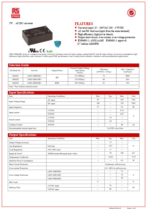
5W, AC/DC converterRoHSFEATURES● Universal input: 85~264V AC/100~370VDC● AC and DC dual-use (input from the same terminal) ● High efficiency, high power density● Output short-circuit, over-current, over-voltage protection ● EN60601-1, ANSI/AAMI ES60601-1 approval (3rd edition 2xMOPP)LD05-20BxxMU series is a compact size power converter. It features universal input voltage, taking both DC and AC input voltage, low power consumption, high efficiency, high reliability, safer isolation. It offers good EMC performance, and is widely used in medical, industrial and instrumentation applications.Selection GuideRS Stock No. Part No. Output PowerNominal Output V oltageand Current (V o/Io)Efficiency (230V AC, %/Typ.)Max. Capacitive Load*(µF)1446281 LD05-20B05MU 5W 5V/1000mA 76 4000 1446282 LD05-20B12MU 12V/420mA 80 820 1446283 LD05-20B24MU5.5W24V/230mA81330Note: *Test without external circuit.Input SpecificationsItemOperating Conditions Min. Typ. Max. Unit Input V oltage Range AC input 85 -- 264 V AC DC input 100 -- 370 VDC Input frequency 47 -- 63 HzInput current115V AC -- -- 0.12 A 230V AC -- -- 0.07 Inrush current 115V AC -- 10 -- 230V AC -- 20 -- Leakage Current264V AC ----80uA Recommended external input fuse2A/250V , slow blowOutput SpecificationsItemOperating Conditions Min. Typ. Max. UnitOutput V oltage Accuracy-- ±2 -- % Line Regulation Full load -- ±0.5 -- Load Regulation 10%-100% load-- ±1 -- Ripple & Noise* 20MHz bandwidth (peak-peak value)-- 50 100 mV Temperature Coefficient -- ±0.02 -- %/℃ Stand-by Power Consumption----0.3W Short Circuit Protection Continuous, self-recovery Over-current Protection110 - 280% Io self-recoveryOver-voltage Protection LD05-20B05MU -- -- 7.5 VLD05-20B12MU -- -- 16 LD05-20B24MU-- -- 30 Min. Load0 -- -- % Hold-up Time115V AC input -- 10 -- ms 230V AC input --80--General SpecificationsItem Operating Conditions Min. Typ. Max. Unit Isolation V oltage Input-output Test time: 1min 4000 -- -- V AC Operating Temperature -25 -- +70℃Storage Temperature -40 -- +85Max. Casing Temperature -- -- +95Storage Humidity -- -- 95 %RHWelding Temperature Wave-soldering 260±5℃; time:5~10s Manual-welding 360±10℃; time:3~5sSwitching Frequency -- -- 140 kHzPower Derating -25 ~ 0℃ 1 -- -- %/℃+55 ~ +70℃ 2 -- -- %/℃Safety Standard EN60601/UL60601Safety Certification EN60601/UL60601Safety Class CLASS IIinsulation Level Primary to Secondary2xMOPPMTBF MIL-HDBK-217F@25℃ >300,000 h Physical SpecificationsCasing Material Black flame-retardant and heat-resistant plastic (UL94-V0)Package Dimensions 53.80*28.80*19.00 mmWeight 43g (Typ.)Cooling method Free air convectionEMC SpecificationsEMI CE CISPR11/EN55011 CLASS B RE CISPR11/EN55011 CLASS BEMS ESD IEC/EN61000-4-2 Contact±6KV/Air±8KV Perf. Criteria B RS IEC/EN61000-4-3 10V/m perf. Criteria AEFTIEC/EN61000-4-4 ±2KV perf. Criteria BIEC/EN61000-4-4 ±4KV (See Fig. 2 for recommended circuit) perf. Criteria B SurgeIEC/EN61000-4-5 ±1KV perf. Criteria BIEC/EN61000-4-5 ±2KV/±4KV (See Fig. 2 for recommended circuit) perf. Criteria B CS IEC/EN61000-4-6 10 Vr.m.s perf. Criteria A PFM IEC/EN61000-4-8 10A/m perf. Criteria A V oltage dips, short interruptions andvoltage variations immunityIEC/EN61000-4-11 0%-70% perf. Criteria BProduct Characteristic Curve-25 0 55 701007075O u t p u t P o w e r P e r c e n t a g e (%)Amb ie nt T e mp e ra ture ()℃T empe rature Dera ting Curve100~264VAC 120~370VDCInp ut vo lta g e:1007010085264120100370VAC VD C240340Input Volta ge De ra ting CurveAmb ie nt te m p e ra ture :25℃Inp ut Vo lta g eO u t p u t P o w e r P e r c e n t a g e (%)Note: Input voltage should be derated based on temperature derating when it is 85~100VAC/100~120VDC;This product is suitable for use in natural air cooling environments, if in a closed environment, please contact our company’s FAE.L D05-20B05MU50 55 6065 70 75 80 85 9095 100 85V110V120V220V240V264VE f f i c i e n c y (%)Input Voltage(V)E fficiency Vs Input Voltage (F ull L oad)L D05-20B05MU5055 6065 70 75 808590 10254050657590100E f f i c i e n c y (%)Output Cur r ent Per centage(%)E fficiency Vs Output L oad(Vin=230VAC)L D05-20B24MU50 556065 70 75 80 859095 100 85V110V120V220V240V264VE f f i c i e n c y (%)Input Voltage(V)E fficiency Vs Input Voltage (F ull L oad)L D05-20B24MU5055 6065 70 75 808590 10254050657590100E f f i c i e n c y (%)Output Cur r ent Per centage(%)E fficiency Vs Output L oad(Vin=230VAC)Design Reference1. T ypical application circuitAC (L )+Vo-VoA C (L )AC (N)AC(N)C 1C 2L O ADF US E AC /DCM O VN T CFig. 1: Typical application circuitModelC1(µF) C2(µF) LD05-20B05MU 1220 LD05-20B12MU 100 LD05-20B24MU47Note:Output filtering capacitor C2 is electrolytic capacitor, it is recommended to apply electrolytic capacitor with high frequency and low resistance. For capacitance and current of capacitor please refer to manufacture’s datasheet. Capacitance withstand voltage derating should be 80% or above. C1 is ceramic capacitor, which is used to filter high-frequency noise. External input NTC is recommended to use 5D-9. External input MOV is recommended to use S14K300. External input FUSE is recommended to use 2A/250V , slow blow.2. E MC solution-recommended circuitAC DCAC (N)AC (L)LCMM OVC XC Y1C Y2FUSEAC (N)AC (L)+Vo-Vo+L1C1C2R LC a n us e MO RNS UN’s FC -L X1DNT CFig 2: EMC Recommended circuit with higher requirementsElement modelRecommended valueMOV S14K300 CX 0.1µF/275V AC L1 4.7uH/2.0A CY1 1nF/400V AC CY2 1nF /400V ACNTC 5D-9LCM 2.2mH, recommended to use MORNSUN’s FL2D -10-222FUSE 2A/250V , slow blow, necessaryFC-LX1DEMC FilterDimensions and Recommended LayoutNote:1.If the product is not operated within the required load range, the product performance cannot be guaranteed to comply with all parameters in the datasheet;2.Unless otherwise specified, parameters in this datasheet were measured under the conditions of Ta = 25℃, humidity <75% with nominal input voltage andrated output load;3.All index testing methods in this datasheet are based on our Company’s corporate stan dards;4.The performance parameters of the product models listed in this manual are as above, but some parameters of non-standard model products may exceed therequirements mentioned above. Please contact our technicians directly for specific information;5.We can provide product customization service;6.Specifications are subject to change without prior notice.。
Keysight PXI GSM EDGE 测量套件数据手册说明书
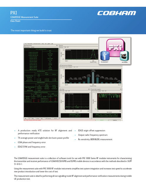
• A product i on ready ATE solut i on for RF al i gnment and performance verification•TX average power and single/multi slot burst power profile•GSM phase and frequency error •EDGE EVM and frequency error•EDGE origin offset suppression •Output radio frequency spectrum •Rx sensitivity (BER/BLER) measurementThe GSM/EDGE measurement suite is a collection of software tools for use with PXI 3000 Series RF modular instruments for characterising the transmitter and receiver performance of GSM/HSCSD/GPRS and EGPRS mobile devices in accordance with the methods described in 3GPP 51-010-1.Using the measurement suite with PXI 3000 RF modular instruments simplifies test system integration and increases test speed to accelerate new product introduction and lower the cost of test.The measurement suite is ideal for performing all non signalling mode RF alignment and performance verification measurements during mobile UE production test.The measurement suite components can be used for applications spanning bench-top manual operation in R&D to high volume production ATE.•Measurement and analysis component libraries provide programming APIs for highly customised ATE system integration for design validation or production.•An easy to use and versatile graphical user interface enables bench-top manual operation using PXI Studio 2 for design integration or trouble shooting•A test sequencer provides an out of the box production ready ATE solution using PXI Maestro software.The test sequencing feature provides an off the shelf production ready ATE solution for testing up to four devices in parallel. This includes fully integrated tester and device control providing the user the ability to write and execute a custom test sequence optimized for speed with ease.The test sequencing feature is an optional extension to the measurement suite used with PXI Maestro software.Manual operation uses PXI Studio 2 application software. This intuitive software, common to all measurement suites, allows the user to configure instrument and measurement parameters, execute measurements and display results.Measurements can be performed for either single or multiple active-slot GSM frames. Burst detection and signal analysis is performed on either Normal or Access burst types with automatic detection of modulation type from GMSK or 8PSK and automatic detection of training sequence (TSC). Measurement results are output as either numerical values with/without statistics or graphical trace displays.Signal generation waveforms provide downlink broadcast, control and data channels to simulate a BTS. These signals enable the mobile device to synchronise and perform receiver sensitivity measurements either as a single BER/BLER measurement or using loopback methods as defined in ETSI TS 100 293-GSM 04.14PXI Maestro and PXI Studi o 2 appli cati on software i s suppli ed free of charge wi th all PXI 3000 modules. Operati on of the GSM/EDGE measurement suite requires simple activation of a license key option on the PXI 3000 hardware. Further information for these applications is available through the following links:PXI StudioPXI MaestroSPECIFICATIONGSM/EDGEAll specifications are defined when used in conjunction with the 3030 Series PXI RF digitizer with option 100 operating in any GSM band between 400 MHz and 2000 MHz.Test sequencing with PXI Maestro additionally requires option 200Specifications are defined with the input signal at the RF digitizer tuned frequency and at the reference level unless otherwise stated. Measurements performed are in accordance with 3GPP TS 151 010-1 section 13 and 14 as applicable.BER/BLER measurements, Burst Timing Error measurements, specific timeslot analysis and multi-DUT operation additionally require a 3020 Series PXI digital RF signal generator to be assigned.CONFIGURATIONFrequencyUplink (Hz)User defined frequency or preset bands, as shown in the table belowBurst TypeGMSK: Auto or Manual (Normal / Access)8PSK: NormalTSC (training sequence)Uplink: Auto or Manual (0 to 7)Path Loss CorrectionTx and Rx (dB)Acquisition Trigger SourceImmediate (free run), Burst (video), Ext (PXI trigger bus, local bus, star trigger, LVDS, TTL)Synchronization (Auto Burst Detection)Burst Detection threshold (dB)Search length (ms)Burst Timing Latency Compensation0 to ±78.125 symbolsBER/BLER LoopbackGSM (Mode A/B)Number of Speech Frames: 1 to 250GSM (Mode C)Number of Burst Frames: 1 to 1000Measurement ResultsUseful Part/Guard (Pass / Fail)Useful Part/Guard Fail time (symbols)Useful Part/Guard Fail level (dB)Values with closest proximity to mask or worst case failure for the complete, rising edge, falling edge, guard and useful parts of the burst. Dynamic RangeTypically -80 dBc (for 3030 Series RF input levels > 0 dBm)Accuracy (rising falling edges)Level: Typically ±0.1 dB /10 dB(1)(relative to peak power)Time accuracy <0.5 μsAccuracy (useful part)Level: Typically ±0.02 dB (relative to peak power)Time accuracy <0.25 symbolAccuracy (Guard)Level: Typically ±0.1 dB /10 dB(1)(relative to peak power)Time Accuracy <0.25 symbolGMSK MODULATIONGMSK phase error measurements performed for a single slotPhase Error Range0 to 100RMS0 to 400peakIndicationResults are expressed as numerical values for RMS + Peak phase errorTracesPeak phase error vs. timeAccuracyBetter than ±0.5° rms phase error ±1.0° peak phase error8PSK MODULATIONThe minimum RMS magnitude of the error vector is calculated for a single slot.Burst TypeNormal onlyEVM Range0 to 20% EVM RMS0 to 40% EVM peakIndicationEVM % (rms and peak), phase error degrees (rms and peak), 95th percentile EVM %, origin offset suppression (dB), and droop (dB) Accuracy±0.4% RMS ±1% peakOffset Origin Suppression Range>20 dB to 60 dB (floor)Offset Origin Suppression Accuracy±0.5 dB at 33 dBNotes(1) Excluding the effects of noise(2) Requires opt 100BLERMeasurement ResultsBlock Error Rate (%)Number of Radio Blocks TestedNumber of Radio Blocks in ErrorNumber of Active Slots Analyzed per frameBER, BER II, RBER II, FERMeasurement ResultsMode C burst loopbackNumber of bits examinedNumber of error bits foundBit Error Rate (%)Mode A/B Speech loopbackNumber of frames examinedErased Speech FramesSpeech Frame Erasure Rate (%)GENERALOperating SystemWindows®7/32-bit or 7/64 bitRequired Memory512 Mbytes minimum, 1024 Mbytes recommendedDisplay ResolutionMinimum 1024 x 768OtherPXI 3000 Series modules require NI VISA version 4.6 or later (NI Visa 4.2 or later). PXI 3000 Series module drivers version 7.0.0 or laterORDERINGGSM/EDGE Measurement SuiteWhen purchased with a 303x, order as: 3030 option 100When purchased as an upgrade, then order as: RTROPT100/3030GSM/EDGE test sequencing (for use with PXI Maestro)(2)When purchased with a 303x, order as: 3030 option 200When purchased as an upgrade, then order as: RTROPT200/3030PXI Studi o 2 and PXI Maestro core appli cati ons are suppli ed as standard wi th PXI 3000 Seri es modules or may be downloaded from/products/validation/modular-instrumentation/pxi/application-software/Cobham Wireless -Validation/wireless Part No.46891/475, Issue 5, 07/15。
VVDI2 – Transponder Programmer User Manual
VVDI2 –Transponder Programmer User ManualTable of Contents1.Document Declaration (4)2.Overview (5)2.1.Noun explanation (5)2.2.Options (5)2.3.Transponder Programming (5)2.4.Special Transponder (6)2.5.Immobilizer Data Tool (6)2.6.Other Key Tool (6)2.7.Prepare Remote (6)2.8.Remote frequency test (6)2.9.IC Chip Program (6)3.Options (7)3.1.Choose Language (7)3.2.Antenna Parameters (7)4.Transponder Programming (8)4.1.Autodetect Transponder (9)4.2.PCF7930/PCF7931/PCF7935 (10)4.3.HITAG2 (11)4.4.HITAG2+ EE (14)4.5.HITAG2 Extended (15)4.6.HITAG3 (16)4.7.HITAG Pro (17)4.8.HITAG (BMW) (18)4.9.HITAG (VAG) (19)4.10.MEGAMOS 13 (20)4.11.MEGAMOS 48 (21)4.12.MEGAMOS 8E (22)4.13.TEMIC 11/ TEMIC 12 (23)4.14.TEMIC 8C (24)4.15.TIRIS 4C (25)4.16.TIRIS DST 4D/TIRIS DST 4E (26)4.17.TIRIS DST+ (27)4.18.T5/TK5551 (28)5.Special Transponder (29)5.1.Mainly function (29)5.2.Support Type (29)5.3.Some Special Transponder Note (32)6.Immobilizer Data Tool (34)6.1.Mainly function – Make a working key (34)6.2.Support Car Type (35)6.3.Special Note (37)7.Other Key Tool (38)8.Prepare Remote (43)8.1.Prepare new remote key (43)1.D ocument DeclarationPlease view the following declaration carefully:◆VVDI2 – Transponder Programmer User Manual can help you maintenance vehiclesand read/write transponder with VVDI2 device. Please DON’T used for illegal purpose, Please follow the national law◆VVDI2 – Transponder Programmer User Manual is written by VVDI2, please DON’Tused for commercial purposes without authorize◆VVDI2 –Transponder Programmer User Manual can help you how to useTransponder Programmer software, please view carefully◆Any illegal use VVDI2 –Transponder Programmer User Manual, illegal useVVDI2 device, The user should take all risks, the company does not assume any responsibility2.O verview2.1.Noun explanation◆Transponder: immo transponder, the transponder inside key, sometimes we call itchip◆sub-remote-pcb: the remote PCB, used in Prepare Remote function. After write datawith remote programmer, it can adapt to car for remote function◆Remote Programmer: It is not standard device, This device can connect to DB15 inVVDI2, it can prepare remote key with sub-remote-pcb◆Byte: a decimal value between 0-255, but we can’t input decimal value, we input hexvalue, every byte between 00-FF.Note: For the byte use in transponder, every input character must belong to 0, 1, 2, 3, 4, 5, 6, 7, 8, 9, A, B, C, D, E, F2.2.OptionsDetail can be found in chapter 3 Options◆Choose Language2.3.Transponder ProgrammingDetail can be found in chapter 4 Transponder ProgrammingSupport auto detect transponder type, support following types:1) PCF7930/PCF7931/PCF79352) HITAG23) HITAG2+ EE4) HITAG2 Extended5) HITAG36) HITAG Pro7) HITAG (BMW)8) HITAG (VAG)9) MEGAMOS1310) MEGAMOS4811) MEGAMOS8E12) TEMIC 11/TEMIC 1213) TEMIC 8C14) TIRIS 4C15) TIRIS DST 4D/4E16) TIRIS DST+17) T5/TK55512.4.Special TransponderDetail can be found in chapter 5 Special TransponderThis function can prepare a blank transponder to special one, just as key ordered by dealer, it can be learned to car with PIN2.5.Immobilizer Data ToolDetail can be found in chapter 6 Immobilizer Data ToolThis function can make a working key directly with immobox EEPROM dump. Support most of the car manufacture2.6.Other Key ToolDetail can be found in chapter 7 Other Key ToolMainly include unlock key, VAG searching 7th bytes CS, VAG prepare dealer with 7 bytes CS, Change MEGAMOS 48 ID etc2.7.Prepare RemoteDetail can be found in chapter 8 Prepare RemoteThis function use Remote Programmer write special data to sub-remote-pcb, make sub-remote-pcb become an original remote key, it can adapt to car for remote function2.8.Remote frequency testJust provide power to VVDI2, place remote key on CHECK area, CHECK area is on VVDI2 device, Press button “F”, then press any button of your remote key, the frequency and type will display on VVDI2 LCD display2.9.IC Chip ProgramAttention: this function not support now3.O ptions3.1.Choose LanguageSupport following languages:◆Chinese (Simplified)◆EnglishPlease manual set user language after first run program3.2.Antenna ParametersYou can make the antenna more stable with change gain value (PICTURE 3.1)For every key is different from each other, the transponder is different position in the key, Thus will cause bad answer while access transponder. You can change antenna gain to large the sensing range, make antenna access the far away transponderAntenna gain value can be 0, 1, 2, 3When gain value smaller, the sensing range will be small and lower. If the transponder position is higher from antenna, the access may failedWhen gain value larger, the sensing range will be large and higher. If the transponder position is lower from antenna, the access may failedSimply:If the transponder position is far away from antenna, you need select higher gain for access, example: 2 or 3If the transponder position is nearby or in antenna, you need select lower gain for access, example: 0 or 1(PICTURE 3.1)4. Transponder ProgrammingSupport following types:1) Autodetect Transponder2) PCF7930/PCF7931/PCF79353) HITAG24) HITAG2+ EE5) HITAG2 Extended6) HITAG37) HITAG Pro8) HITAG (BMW)9) HITAG (VAG)10) MEGAMOS1311) MEGAMOS4812) MEGAMOS8E13) TEMIC 11/TEMIC 1214) TEMIC 8C15) TIRIS 4C16) TIRIS DST 4D/4E17) TIRIS DST+18) T5/TK55514.1.Autodetect Transponder(PICTURE 4.1)Input transponder to VVDI2 programmer, press button “Autodetect Transponder”, it will detect transponder type and simple status information. You can turn to specify type after success read (PICTURE 4.1). Autodetect Transponder function can run without software, just provide power to VVDI2, press button “T” on the device, transponder type will show in the LCD display4.2.PCF7930/PCF7931/PCF7935Many old cars use this transponder as immo transponder, this transponder support generate many types special transponder. It mainly contains Password, Main memory, Shadow memory etc. Note: PCF7930 and PCF7931dont have Shadow memory, only have Main memory. PCF7935 have this 2 memory both. Shadow memory only has 16 bytesWrite: You need read transponder success before write, modify the position to your expect value, the byte will change read after edit, then write to transponder(PICTURE 4.2)(PICTURE 4.2)Read Transponder: Read Main memory don’t require passwordWrite: For the transponder enabled Password feature, you must place correct password in Password area before write4.3.HITAG2HITAG2 is very popular immo transponder(PICTURE 4.3),it is compatible with PHILIPS PCF7936 transponders. It support following types:PCF7936PCF7941PCF7942/44PCF7943PCF7945PCF7946PCF7947PCF7952PCF7953PCF7961(There’s some other HITAG2 transponder made by small company, it don’t have the above type, but also support)Access method:PCF7936 support Password mode and Cipher modeOther’s don’t have Password mode itself, only have Cipher modeFor Password mode: Only SK low was used for login,Default key:4D494B52For Cipher mode: It use SK low and SK high for login,Default key:SK low:4D494B52;SK high: 4F4ECoding method:Support Manchester and Biphase coding (Note: Most immo transponder use Manchester coding, rarely use Biphase type)(PICTURE 4.3)◆Read TransponderIt will read all readable page and shown in window (Transponder information, Transponder data, Remote control(not all transponder have this area)),it will try password mode and cipher mode automatically, also Manchester and Biphase automatically. For the transponder with default key we can read all readable pages. If the transponder was changed SK value, we can only read ID before you input correct SK value in Parameter. Every page in HITAG2 has 4 bytes. The type is detect with identifier, so it will not strictly for many OEM keys◆About the transponder manufacture configuration(TMCF)TMCF byte is very important; usually it is the first byte in Config page. Example: Config page is “XXYYZZWW”(4 bytes). The first byte “XX”is TMCF,write error TMCF value can lock the transponder or damage it. The specify explanation for TMC following: Convert XX(hex) to binary, it have 8 bits, every bit can be 0 or 1, we set as: X1 X2 X3 X4 X5 X6 X7 X8X1: If set to 1, the SK low and SK high was unable to read and writeX2: If set to 1, the Config page was unable to write, but read is always availableX3: If set to 1, Remote control area was unable to read and write(Note: PCF7936 have none about this bit)X4: If set to 1, transponder data was unable to write, but read is always available X5: If set to 1, transponder is use transponder data area. If set to 0, mean use remote control area (Attention: For PCF7936, if set to 1, transponder use Cipher mode, if set to 1, transponder use Password mode)X6: Always 0, reserve bit (Attention: PCF7936 must set to 1, set to 0 will damage transponder)X7: Always 0, reserve bit (Attention: PCF7936 must set to 1, set to 0 will damage transponder)X8: If set to 0, transponder use Manchester coding, if set to 1, use Biphase coding (CDP)How to change a byte to binary: With PC system Calculator ->Select Scientific->Select Hex ->input TMCF value ->Select Bin, you can see the binary values. If binary not have total 8 bits, means the front have several 0Example: TMCF value is C8, so X1-X8 have value: 11001000The transponder use Manchester codingThe transponder use transponder data areaThe SK low and SK high was unable to read and writeThe Config page was unable to write, but support read4.4.HITAG2+ EESupport read EEPROM data for PCF7952, PCF7945, PCF7953 etc. (Note:Standard access method for HITAG2+ EEPROM, just like Hyundai, Kia keys. BMW key not belong to this type)(PICTURE 4.4)(PICTURE 4.4)4.5.HITAG2 ExtendedSupport read/write EEPROM data for HITAG2 Extended transponder, mainly used n GM cars. You can read with SK values. Enable SK will read more data compared with not enable SKWrite: You need read transponder success before write, modify the position to your expect value, the byte will change read after edit, then write to transponder (PICTURE 4.5)(PICTURE 4.5)4.6.HITAG3Support read EEPROM data for HITAG3 (Some new key in Nissan use this type)(PICTURE 4.6)(PICTURE 4.6)4.7.HITAG ProHITAG Pro transponder, now we know BMW F-Series keys, new Porsche keys belong to this type. Support read EEPROM data (PICTURE 4.7)(PICTURE 4.7)Support read/write EEPROM data for BMW remote (keyless) keys.Write: You need read transponder success before write, modify the position to your expect value, the byte will change read after edit, then write to transponder(PICTURE 4.8)(PICTURE 4.8)HITAG (VAG) is a special transponder for VAG immo5 keys. It can read EEPROM data. As we know, A4/A5/A6/A7/A8/Q5/Touareg cars with immo5 system use this type key (PICTURE 4.9)(PICTURE 4.9)4.10.MEGAMOS 13MEGAMOS 13 only have a data stream.Support copy transponder: Just write the transponder identifier to the simulate transponder (T5 or PCF7935)(PICTURE 4.10)(PICTURE 4.10)MEGAMOS 48 have 16 pages(PICTURE 4.11),We can read Page0-Page4, Page15-Page12. Other pages only have write operation. Every page has 2 bytes(PICTURE 4.11)◆Read TransponderRead identifier (Page3/Page2), config page (Page1, Page0) and user page (Pager15-Page12)If page 1 shown with red mean the transponder is locked. You can’t write any data to locked transponderAbout change MEGAMOS 48 identifier: see Change megamos 48 ID in chapter 7 Other Key Tool◆PIN / UnlockThe PIN code is stored in Page11, Page10,this 2 pages is write only page. You can lock the transponder to blank one with button “Unlock” and correct PIN codeAttention: Electronic MEGAMOS 48 made by VAG don’t support unlock operation◆Crypto KeyMEGAMOS 48 have 12 bytes crypto key, stored in page9-page4Input correct key in page9-page4 (not write, only input), Press button “Verify”, you can verify the crypto key with values stored in transponderMEGAMOS 8E transponder (PICTURE 4.12), mainly contain identifier, Data area, Crypto key area. This transponder usually used in A6/Q7/Allroad (EZS-Kessy J518 4th immobilizer system)(PICTURE 4.12)Read Transponder: It can read identifier, and 8 pages data area. Every page has 2 bytesCrypto key area: This area only support write. It contain the crypto key, total 12 bytes Unlock: You can unlock the transponder to blank with correct crypto keyCheck Blank: Check transponder locked or not, the transponder will locked immediately after write crypto key4.13.TEMIC 11/ TEMIC 12TEMIC 11和TEMIC 12芯片非常接近, 通讯方式略有不同. 对于标准的芯片来说, TEMIC 11芯片默认头部为BEFA, TEMIC 12芯片默认头部为660F或66F0. 可以使用自动搜索,也可以通过移位功能手动搜索(PICTURE 4.13). 此芯片只有一个数据流信息, 支持芯片拷贝.拷贝只要把原始芯片ID写入到T5模拟芯片中(PICTURE 4.13)TEMIC 8C芯片只有一个数据流信息(PICTURE 4.14)(PICTURE 4.14)TIRIS 4C only have a Data stream (PICTURE 4.15)Support copy transponder: Just write the Tiris 4C data to TIRIS 4C or TPX1(PICTURE 4.15)4.16.TIRIS DST 4D/TIRIS DST 4ETIRIS DST 4D is very similar with TIRIS DST 4E,they have same data area and algorithm, crypto key is 40 bit(5 bytes) stored in page 4. The only different is they have different coding method, so this 2 transponder can’t instead each other (PICTURE 4.16)(PICTURE 4.16)◆Read Transponder: Read Page1-Page4 (default key can read for page4) and getlock status. If the page was locked, you can’t write data anymore. Page3 usually use as identifier, it combined with 3 bytes Serial and 1 bytes manufacture code◆Write: Write data to unlock page. Page1 and Page2 have 1 byte, Page3 have 4 bytes,Page4 have 5 byes◆Lock: It can protect the page for write operation◆TIRIS crypto verify: This function can verify the stored crypto key (page4) right ornotCheck TIRIS response (40 bits): VVDI2 send the seed to transponder and read the crypto value (3 bytes)Calc TIRIS response (40 bits): VVDI2 have the algorithm for TIRIS 40 bits, we can calculate the seed and key, get right crypto value (3bytes). Compare this value with transponder response value, if they are same, the transponder have same crypto key as you input. (Attention:For some special crypto key, you need check several different seed for the verify)4.17.TIRIS DST+TIRIS DST+ support 2 algorithm, one is same as TIRIS DST 4D (40 bits), another is 80 bits (10 bytes) algorithm (Toyota G transponder use this type). It have same coding method with TIRIS DST 4D,so if the transponder deploy to 40 bits method, it can instead TIRIS DST 4D transponder(PICTURE 4.17)(PICTURE 4.17)◆Read Transponder: Read Page1, Page2, Page3, Page4 (Default key can be read),Page8-Page12, Page29, Page30 and lock status. If the page was locked, you can’t write data anymore. Page3 usually use as identifier, it combined with 3 bytes Serial and 1 bytes manufacture code◆Write: Write data to unlock page. Page1 and Page2 have 1 byte, Page3 have 4 bytes,Page30 have 2 bytes, other’s page all have 5 bytes◆Lock: It can protect the page for write operation◆TIRIS crypto verify: This function only support verify 40 bits methodtransponderCh Check TIRIS response (40 bits): VVDI2 send the seed to transponder and read the crypto value (3 bytes)Calc TIRIS response (40 bits): VVDI2 have the algorithm for TIRIS 40 bits, we can calculate the seed and key, get right crypto value (3bytes). Compare this value with transponder response value, if they are same, the transponder have same crypto key as you input. (Attention:For some special crypto key, you need check several different seed for the verify)4.18.T5/TK5551T5/TK5551 is a very useful transponder; it can simulate many other transponders. The Data area only support write. Simulate require write different config and data. Attention: This transponder is very complex, you’d better not write data manually, use function provide by VVDI2, write error data can damage transponder (PICTURE 4.18)(PICTURE 4.18)5.S pecial Transponder5.1.Mainly functionSpecial Transponder, it can prepare a special transponder (original manufacture key). It can be learned to car with PIN code(PICTURE 5.1)(PICTURE 5.1)5.2.Support TypeSupport following types:1) TP22 (Seat-CAN) --- Megamos Crypto 482) TP23 (Volkswagen-CAN) --- Megamos Crypto 483) TP24 (Skoda-CAN) --- Megamos Crypto 484) TP25 (Audi-CAN) --- Megamos Crypto 485) ID33 Citroen/Peugeot/Fiat/Lancia VALEO --- PCF79356) ID33 Fiat BOSCH --- PCF79357) ID33 Mazda --- PCF79358) ID33 Mitsubishi --- PCF79359) ID33 Nissan --- PCF793510) ID33 Nissan 2 --- PCF793511) ID33 Opel/Vauxhall/Cadillac/Holden --- PCF793512) ID33 Opel/Vauxhall/Cadillac/Holden 2 --- PCF793513) ID33 Volkswagen --- PCF793514) ID40(44) China Cars --- PCF793515) ID40 Opel/Vauxhall/Cadillac/Holden --- PCF793516) ID41 Nissan --- PCF793517) ID42 Volkswagen --- PCF793518) ID44 Mitsubishi --- PCF793519) ID44 Volkswagen 1 --- PCF793520) ID44 Volkswagen 2 --- PCF793521) ID45 Peugeot --- PCF793522) ID46 China Cars --- PCF793623) ID46 VAG --- PCF793624) ID46 Nissan X-Trail25) ID46 Nissan Platina26) ID46 Nissan Keyless --- Key Card27) ID46 Infinity Keyless --- Key Card28) ID46 Nissan Micra --- Remote Key29) ID46 Nissan Tida --- Remote Key30) ID46 Renault Master II --- Remote Key31) ID46 Renault Clio II --- Remote Key32) ID46 Renault Master II --- Transponder 793633) ID46 Renault Trafic II --- Remote Key34) ID46 Renault Trafic II --- Transponder 793635) ID46 Nissan Primastar --- Remote Key36) ID46 Nissan Primastar --- Transponder 793637) ID46 Nissan Interstar --- Remote Key38) ID46 Nissan Interstar --- Transponder 793639) ID46 Opel Astra H / Zafira B --- Remote Key40) ID46 Opel Corsa D --- Remote Key41) ID46 Opel Vectra C --- Remote Key42) ID46 Opel Vivaro --- Remote Key43) ID46 Opel Vivaro --- Transponder 793644) ID46 Opel Movano --- Remote Key45) ID46 Opel Movano --- Transponder 793646) ID46 Opel Movano III --- Remote Key47) ID46 Renault Master III --- Remote Key48) ID46 Renault Clio III --- Remote Key49) ID46 Renault Modus III --- Remote Key50) ID46 Renault Espace IV --- Transponder 793651) ID46 Renault Espace IV --- Key Card 2-buttons52) ID46 Renault Espace IV --- Key Card 3-buttons53) ID46 Renault Laguna II --- Transponder 793654) ID46 Renault Laguna II --- Key Card 2-buttons55) ID46 Renault Laguna II --- Key Card 3-buttons56) ID46 Renault Laguna III --- Key Card57) ID46 Renault Vel Satis --- Transponder 793658) ID46 Renault Vel Satis --- Key Card 2-buttons59) ID46 Renault Vel Satis --- Key Card 3-buttons60) ID46 Renault Megane II --- Key Card61) ID46 Renault Scenic II --- Key Card62) ID46 Renault Twingo --- Remote key63) ID46 Renault Twingo --- Transponder 793664) ID46 Citroen/Fiat/Lancia/Peugeot --- PCF793665) ID46 Citroen/Peugeot --- PCF793666) ID46 Citroen/KIA/Hyundai/Peugeot --- PCF793667) ID46 Fiat/Iveco --- PCF793668) ID46 Renault/Chrysler --- PCF793669) ID46 Chrysler CAN bus (Y164,Y170) --- PCF793670) ID46 Chevrolet Circle Plus --- PCF793671) ID46 Mitsubishi --- PCF793672) ID46 Saab73) ID46 Hyundai Remote key 794674) ID46 KIA Remote key 794675) ID60 Generic --- Texas 4D76) ID61 Mitsubishi II --- Texas 4D77) ID62 Suzuki BIKE --- Texas 4D78) ID62 Kawasaki BIKE --- Texas 4D79) ID62 Mitsubishi III --- Texas 4D80) ID63 Ford/Mazda --- Texas 4D81) ID64 Chrysler/Subaru --- Texas 4E82) ID65 Suzuki/Subaru --- Texas 4D83) ID66 Suzuki --- Texas 4D84) ID67 Toyota --- Texas 4D85) ID68 Lexus --- Texas 4D86) ID69 Yamaha --- Texas 4D.(JMA TP31)87) ID70 Toyota Europe --- Texas 4D88) ID70E Toyota Hybrid --- Texas 4D89) ID73 Mitsubishi --- PCF793590) ID8C Ford/Mazda --- Temic 8C91) ID8C Proton --- Temic 8C92) Mercedes Benz G- Class --- PCF 793093) Mercedes Benz C- Class/E- Class --- PCF 793094) Mercedes Benz ML --- PCF 793095) VW Jetta 2010 (China) --- Megamos Crypto 485.3.Some Special Transponder Note◆ID40(44) China cars --- PCF7935: this type need select sub type: Chery, Geely,Great Wall, Haima, ChangAn (PICTURE 5.2)(PICTURE 5.2)◆ID46 China cars --- PCF7936: this type need select sub type: Chery, Geely, GreatWall, Haima, Zotye Auto, Maple Auto, Zhonghua 530, Zhonghua 230 (PICTURE 5.3)(PICTURE 5.3)ID67(Toyota)/ID68(Lexus)/ID70(Toyota-Euro)/ID70E(Toyota Hybrid) --- TIRIS 4D: this type need select key position: Master key1, Master key2, Master key3, Master Key4, Valet Key1, Valet Key2 (PICTURE 5.4)(PICTURE 5.4)6. Immobilizer Data Tool6.1.Mainly function – Make a working keyImmobilizer Data Tool, simply name write start. It can load car immobox EEPROM dump, make a working key directly. Provide detail transponder type and EEPROM type accord selected car (PICTURE 6.1): car original transponder, require new transponders, EEPROM chip, EEPROM size etcHow to make a working key with immobox EEPROM dump file, steps:1) Load immobox EEPROM dump (BIN file) with Load EEPROM dump…, it will displayused key ID, key number, and PIN(if it have) etc2) Select a key position for new key3) Input a blank key to VVDI2 programmer, Press button Make Dealer Key4) After make key success, if you get save new EEPROM window, you need write newdump file to immobox to make new key working(Expect there’s special note). If there’s no save new EEPROM window, the made key can start engine directly(PICTURE 6.1)6.2.Support Car TypeSupport following types:◆AsiaAcuraBrillianceBesturnChang AnGreat WallCheryDaewooDaihatsuGeelyHaimaHondaHyundaiInfinitiIsuzuKawasakiKiaLexusMazdaMitsubishiNissanProtonSaicMotorSaipaIKCOSsangYongSubaruSuzukiTataToyotaYamaha◆EuroAlfa RomeoApriliaAston MartinAudiBentleyBMWCitroenDaciaDAFDucatiFerrariFiatGileraIvecoJaguarLanciaLDVMANMaseratiMercedes BenzOpelPeugeotPiaggioPolonezPorscheRenaultRoverSaabScaniaSeatSkodaSmartTagAZUAZVAZVolvoVW◆USABuickBombardierCadillacChevroletChryslerDodgeFordGMCJeepLincolnOldsmobilePontiac6.3.Special Note◆You’d better use VVDI Programmer for read Immobox EEPROM dump file◆When you save new EEPROM dump, DON’T write to original dump file, save a newname◆For VAG CDC32xx type, some type need FLASH for make dealer key◆For BMW CAS3+ encrypt version, we need working key, engine EEPROM dump orISN support (PICTURE 6.2)◆For some special immobox, VVDI2 can fix the crashed EEPROM dump to new one.Please load new saved EEPROM dump and make key◆Porsche support Erase key, after ease key will save new dump. Make dealer keyshould load new dump(PICTURE 6.3)(PICTURE 6.2)(PICTURE 6.3)7. Other Key ToolMainly include following types, there will be a steps after select one item◆Unlock – Megamos 48 transponder: Unlock all dealer key prepared by VVDI2 (Expectelectronic MEGAMOS 48) (PICTURE 7.1)◆Unlock – A6/Q7/Allroad Key (MEGAMOS 8E): Require load J518 EEPROM(PICTURE7.2)◆Unlock – PassatB6/CC 46 transponder key (need 95320 EEPROM): Require comfort◆◆◆th ◆◆in(PICTURE 7.1)(PICTURE 7.2)(PICTURE 7.3)(PICTURE 7.4)(PICTURE 7.5)(PICTURE 7.6)(PICTURE 7.7)(PICTURE 7.8)8. Prepare Remote8.1.Prepare new remote keyThis function can write special data to sub-remote-pcb via Remote Programmer(PICTURE8.1). Make sub-remote-pcb have original remote key function (PICTURE 8.2)◆Requires connect Remote Programmer to VVDI2 DB15 Interface. RemoteProgrammer is not a standard device, you can connect your dealer for detail◆Have offline database, and can update database via internet automatically◆Choose specify remote type, connect Remote Programmer to VVDI2 DB15 interface,and connect another head to sub-remote-pcb. Press “Prepare Remote” and wait end ◆After write success, the sub-remote-pcb have same function as original remotekey, What you need to do is adapt the sub-remote-pcb to car◆About Prepare from file: If you select this option, it will ask you load a remote filewhen prepare remote. Attention: the file must get from VVDI2. Write other data may damage sub-remote-pcb◆Feedback: You can feedback any question in prepare remote here. Just write yourquestion and contact method and feedback to VVDI2(PICTURE 8.1)(PICTURE 8.2)。
altium窗口菜单中英文对照表
- ..Altium_Designer(protel_DXP)英文菜单汉化对应表表2021-01-08 17:065964人阅读评论(0)收藏举报分类:硬件〔100〕%s - No SI model for part%s - 没有部件的SI模型%s Degrees%s 度%s mm%s 毫米%s object selected in %s document在%s个文档有%s个对象被选中%s Objects Displayed (%s Selected)%s 对象显示(%s 被选择)%s objects selected%s 对象被选择(custom)(自定义)(pixels)(像素)+12 Power Port+12 电源端口+5 Power Port+5 电源端口-5 Power Port-5 电源端口0 Hidden ment strings0 隐藏注释行0.01uF Capacitor0.01uF 电容0.1uF Capacitor0.1uF 电容1 Locked ponents1 锁定元件1 By Ascending X Then Ascending Y根据X递增量决定Y递增量1.0uF Capacitor1.0uF 电容100K Hertz Pulse100KHz 脉冲100K Hertz Sine Wave100KHz 正弦波100K Resistor100K 电阻10K Hertz Pulse10KHz 脉冲10K Hertz Sine Wave10KHz 正弦波10K Resistor10K 电阻10uF Capacitor10uF 电容1K Hertz Pulse1KHz 脉冲1K Hertz Sine Wave1KHz 正弦波1K Resistor1K 电阻1M Hertz Pulse1MHz 脉冲1M Hertz Sine Wave1MHz 正弦波2 Pads and vias with a hole size between 15and 302 焊盘和过孔的孔大小在15-30之间2.2uF Capacitor2.2uF 电容4 All testpoints4 全部测试点4 Port Serial Interface4 端口串行接口4.7K Resistor4.7K 电阻47K Resistor47K 电阻5 ponent track and arc silkscreenprimitives5 元件丝印层的根本线和弧线A KeywordA关键字Abort Simulation终止仿真About Design Explorer关于设计浏览器Absolute绝对Absolute Layer绝对层Absolute Origin绝对原点AC Small Signal Analysis Setup交流小信号分析配置Accept Changes (Create ECO)成认改变(建立ECO)Access Code验证码Accuracy精度Activates open documents激活显示文本Active Low Input激活低电平输入Active Low Output激活低电平输出Active project当前激活工程Active sheet当前激活图纸Active Signals激活的信号Add All添加全部- ..Add All Waveforms添加全部波形Add as Rule作为规那么添加Add Assembly Outputs增加装配输出Add Class添加分类Add ponent Part添加元件部件Add Document增加文本Add Document to Focused Project添加文档到当前工程Add Documentation Outputs增加文本输出Add Existing Project添加已存在的工程Add Fabrication Outputs增加生产输出Add first condition添加首要条件Add From To添加From ToAdd Internal Plane增加电层Add Layer添加层Add Library添加库Add License添加许可证Add Net添加网络Add Net Class添加网络分类Add Netlist Outputs增加网表输出Add New Cursor增加标Add New Model添加新模式Add New Project添加新工程Add One添加一个Add or Remove Libraries添加或移出库文件Add Other Outputs添加其他输出Add Plane添加电层Add Plot增加图表Add Project To Version Control将工程添加到版本控制Add Remove ponent Libraries添加移出元件库Add Remove Libraries添加/移出库文件Add Reports增加报告Add Selected添加选择的Add Selected Primitives to ponent添加所选根本元素到元件Add Sheet Entry添加图纸入口Add Signal Layer增加信号层Add Suffix加后缀Add Template to Clipboard添加模板到剪贴板Add To Current Sheet添加到当前图纸Add to Custom Colors添加到自定义颜色Add To Design添加到设计Add To Entire Project添加到整个工程Add to new Y axis增加到新Y轴Add to Project添加到工程Add To Sheet添加到图纸Add To Version Control添加到版本控制Add top level signals to waveform给波形增加顶层信号Add Variant添加变量Add Watch增加监视Add Wave增加波形Add Wave To Plot给图表增加波形Add Waveform增加波形Add waveforms to the new plot给新图表增加波形Add Y Axis增加Y 轴Add/Edit Model增加/编辑模型Add/Remove Libraries装载/移出库文件Add/Remove Library装载/移出库AddAlias添加别名Advanced (Query)高级(查询)Advanced Mode高级模式Affected Document所影响的文本- ..Affected Object所影响的对象Aggregate合计Align Bottom底部对齐Align ponents对齐元件Align ponents by Bottom Edges根据元件下缘对齐Align ponents by Horizontal Centers元件居中对齐Align ponents by Left Edges元件左边对齐Align ponents by Right Edges元件右边对齐Align ponents by Top Edges元件对齐顶部边缘Align ponents by Vertical Centers根据垂直中心对其元件Align Left左对齐Align Right右对齐Align Top顶部对齐Aligned - Bottom对齐- 底部Aligned - Center对齐- 中心Aligned - Inside Left对齐- 部左边Aligned - Inside Right对齐- 部右边Aligned - Left对齐- 左边Aligned - Right对齐- 右边Aligned - Top对齐- 顶部all全部All ponents全部元件All Draft全部草图All Final全部最终All Hidden全部隐藏All Locked全部锁定All Nets全部网络All Off全部关闭All On全部翻开All On Current Document全部当前文档All on Layer全部翻开层All open schematic documents所有翻开原理图文档All Orientations所有方向All schematic documents in the currentproject当前工程中所有原理图文档All Text Docs全部文本文件Allow Dock允许停放Allow multiple testpoints on same net允许同一网络多个测试点Allow Ports to Name Nets允许端口到网络名Allow Sheet Entries to Name Nets允许图纸入口到网络名Allow Short Circuit允许电路短路Allow Synchronization With Database允许和数据库同步Allow Synchronization With Library允许和库同步Allow testpoint under ponent元件下允许测试点Allow Vias under SMD PadsSMD焊盘下允许过孔Allowed Orientations允许方向Allowed Side and Order允许边和定制Alpha字母Alpha Numeric字母数字Alpha Numeric Suffix字母数字下标Alphabetically字母顺序Alternate 1另一选择1Alternative其他选择Always load error file总是加载错误文件Amplitude振幅Analog模拟Analog +12V (+12V)模拟+12V (+12V)Analog +5V (+5V)模拟+5V (+5V)Analog Ground (AGND)模拟地(AGND)Analog Routing 1模拟布线层1Analog Routing 2模拟布线层2- ..Analog Routing 3模拟布线层3Analog Signal In模拟信号输入Analyse分析Analyses Setup分析配置Analyses/Options分析/选项Analysis分析Analysis Errors分析错误Analyze Design分析设计Analyze Document分析文档And Gate与门And to wrap long lines增加到可交换长行Angular角形Angular Dimension角度Angular Step角幅Animation speed动画速度Annotate标注Annotation注释Anode正极ANSIANSIAny任何Aperture File (using Wizard formats)光圈文件(利用向导格式) Aperture Library光圈库Aperture List光圈列表Aperture Matching TolerancesD码表匹配公差Append Sheet Numbers to Local Nets附加图纸编号到本地网络Applicable Binary Rules适用的二元规那么Applicable Rules适用的规那么Applicable Unary Rules适用的一元规那么Apply Filter应用过滤器Apply to Active Chart Only仅适用于激活图表Apply to Entire Document适用于整个文本Arc弧线Arc (Any Angle)弧形(任何角度)Arc (Center)弧形(定中心)Arc (Edge)弧形(边限)Arc Line Width弧线宽度Arc Radius圆弧半径Architecture构造Archive project document存档工程文件Arcs弧形Arithmetic算法Around Point附近的点Arrange All Windows Horizontally水平排列所有窗口Arrange All Windows Vertically垂直排列所有窗口Arrange ponents Inside Area在区域排列元件Arrange ponents Within Room在布局空间排列元件Arrange Outside Board在底边界外排列Arrange Within Rectangle在矩形里排列Arrange Within Room在布局空间里排列Arrow Length箭头长度Arrow Line Width箭头线宽度Arrow Position箭头位置Arrow Size箭头大小Arrow Style Power Port发射型电源端口Arrow Width箭头宽度Articles and Tutorials文章和教程Assembly %s装配%sAssembly Drawings装配制图Assembly Outputs装配输出At Margin在页边距- ..At Window在窗口Attributes on Layer层上属性Auto Create posite自动创立合成Auto indent mode自动缩进模式Auto Pan Fixed Jump自动平移固定围Auto Pan Off自动平移关闭Auto Pan Options自动平移选项Auto Pan ReCenter自动平移至中心Auto Placement自动布局Auto Placer自动放置Auto Route自动布线Auto save every自动保存间隔Auto Zoom自动缩放Auto-Increment During Placement在布局时自动增加Auto-Junction自动加节点Auto-Position Sheet自动定位图纸Automatic (Based on project contents)自动〔基于工程容〕Automatically crossprobe first error自动穿插检索第一个错误Automatically Remove Loops自动去除回路Autopan Options自动位移选项Autoposition自动定位Autosave desktop自动保存桌面设置Available Libraries当前库Available Routing Strategies可用的布线策略Available Signals可用的信号Average Track Length (mil)平均铜线长度〔mil〕Avg平均Avoid Obstacle避开障碍物Back Annotate反向标注Background背景Backspace unindents回车取消缩进Backup Files备份文件Backup Options备份选项Ball Grid Arrays (BGA)BGABallistic可变速度移动Bank1组列1Bank2组列2Bar Style Power Port条型电源端口Bar to use as Main Menu栏作为主菜单使用Bar Type栏类型Bars栏Base Value低电平Baseline基线Baseline Dimension基线尺度Basic DC根本直流Batch批处理Batch Mode批命令模式Begin Group开场分组Below is a list of all the processesprovided by this server以以下表是此效劳提供的所有处理模块Beta DegBeta降级Bezier曲线BGA OptionsBGA 选项Bidirectional Signal Flow双向信号流向Bill of Materials材料清单Bill of Materials (By PartType) For Project[%]工程[%s]物料清单(元件类型)Bill of Materials For PCB%sPCB %s材料清单Bill of Materials For Project %s工程材料清单%sBitmap File位图文件Blank Project (Embedded)空白工程(嵌入式)- ..Blank Project (FPGA)空白工程(FPGA)Blank Project (Library Package)空白工程(库包) Blank Project (PCB)空白工程(PCB)Block Indent块缩进Block Name块名称Block Name : %s块名称: %sBoard板Board Area Color板区域颜色Board Dimensions板尺寸Board in 3D3D 板视图Board Information板信息Board La&yers & Colors板层和颜色Board La&yers && Colors板层和颜色Board Layers Colors板层颜色Board Layers & Colors板层和颜色Board Layers and Colors板层和颜色Board Line Color板层线颜色Board Options板选项Board Shape板形Board Specifications板技术参数Bold Waveforms实线波形BOOLEAN布尔数学体系Border (Auto-Detect)边界(自动探测)Border Color边框颜色Border On边框显示Border Width边框宽度Bottom底层Bottom Dielectric底部绝缘层Bottom Layer底层Bottom Layer Annular Ring Size底层圆环尺寸Bottom Overlay底层丝印层Bottom Paste底层焊锡层Bottom Solder底层阻焊层Bottom Solder Mask底层阻焊层BottomLayer底层BottomOverlay底层丝印层Brackets支架Break All ponent Unions从单元中别离出所有元件Break ponent from Union从单元中别离出元件Break Track断开轨迹Breakpoints断点Brightness亮度Bring To Front Of带到某对象前面Browse浏览Browse ponent Libraries浏览元件库Browse ponents浏览元件Browse Libraries浏览库Browse Library浏览库文件Bubble Help Advisor (Shift+F1)浮动帮助参谋(Shift+F1) Build posite构造合成Build Later后来再建Build PCB Project构造PCB 工程Build Project构造工程Build Query构造智能语句Build Sooner立即创立Build-Up绝缘层对Building Query from Board从板构造查询Bus总线Bus Entry总线入口Bus indices out of range总线超出围- ..Bus range syntax errors总线围语法错误Bus Width总线线宽By class通过类By document type通过文本类型C MenuC 菜单C StandardC 标准Calc. Copper Area计算.铜面积Calculated Impedance =计算阻抗=Calculated Trace Width =计算线宽=CAM DocumentCAM 文档CAM EditorCAM 编辑器Cannot Locate Document %s无法找到%s文档信息Capacitance电容Capacitor电容Capacitors电容Categories类别Cathode负极Center Dimension中心点尺度Center Horizontal水平居中Center of Object对象中心Center Vertical垂直居中Change Language更换语言Change Order改变顺序Change System Font改变系统字体Change Technology改变封装技术Channel Offset通道偏移Characteristic Impedance Driven Width特性阻抗驱动线宽Chart制图Chart name is blank图表名称为空Chart Options图表选项Check All ponents检查所有元件Check In签入Check Mode校验模式Check Out签出Check Syntax校验语法Choose a snap grid size选择捕获网格尺寸Choose Color选择颜色Choose cursor to delete选择要光标删除Choose cursor to jump to选择要跳转到的光标Choose Default Backup Folder选择缺省的备份文件夹Choose Default Document Folder选择缺省文档文件夹Choose Design Rule Type选择设计规那么类型Choose Document选择文档Choose Document Scope选择文档围Choose Document to Open选择要翻开的文档Choose Document to Place选择文档放置Choose Documents选择文档Choose Documents to Add to Project %s选择文档加到工程%sChoose Documents To pare选择比拟文档Choose documents to pare - one from theleft list and one from the right list选择比拟文档- 一个从左面列表另一个从右面列表选择Choose Project选择工程Choose Project Group to Open选择要翻开的工程组Choose Project to Open选择要翻开的工程Choose second corner选择第二角Choose the document to pare against thedesign hierarchy of %s选择与设计层次%s进展比拟的文本Choose the document to pare against thedesign hierarchy of Documents.PRJPCB选择与工程文本的层次设计进展比拟的文本Choose Top Level选择顶层- ..Choose WAS-IS File for Back-Annotation fromPCB从PCB选择WAS-IS文件作为反向注释Circle Style Power Port循环型电源端口Circuit电路Circuit Simulation电路仿真CKTCKTClamping箝位Class I分类IClass II分类IIClass Type类型Classes分类Classic Color Set典型颜色设置Clean All Nets去除全部网络Clean Single Nets去除单一网络Clear All Nets去除全部网络Clear All Test points去除全部检测点Clear All Testpoints去除全部测试点Clear Browser Marks去除浏览器标记Clear Class去除类别Clear Current Filter去除当前过滤器Clear Current Filter (Shift+C)去除当前过滤器(Shift+C)Clear Existing去除已存在Clear Filter去除过滤器Clear History去除历史Clear Memory去除存储器Clear non-numerical values去除非数字的值Clear Selected去除已选Clear Status去除状态Clear workspace pile messages onpile编译时去除工作空间编译信息Clearance间距Click Clears Selection单击去除选择Click on the finish button to plete thetask在完毕按钮上点击完成任务Client客户端Client License Usage客户端许可证用法Client Setup客户端设置Clip to Area显示框文本Clipboard Reference剪贴板属性clock时钟Close 'pile Errors'关闭‘编译错误’面板Close 'piled Object Debugger'关闭‘编译对象调试器’面板Close 'Differences'关闭‘差异’面板Close 'Files'关闭‘文件’面板Close 'Help Advisor'关闭‘帮助参谋’面板Close 'Inspector'关闭'检视器'Close 'Libraries'关闭'库'Close 'List'关闭'列表'Close 'Messages'关闭‘消息’面板Close 'navigator'关闭‘浏览器’面板Close 'Projects'关闭‘工程’面板Close All Documents关闭全部文件Close posite关闭合成Close Documents关闭文档Close Focused Project关闭当前工程Close Project关闭工程Close Project Documents关闭工程文档Collapse Row折叠行Collect Data For数据收集类型Collector集电极Color Options颜色选项Color Set颜色设置- ..Colors && Gray Scales色彩/灰度级Colours颜色Column Best Fit适应列宽mand Reference命令参考mand Status命令状态栏ment type注释类型p Drag拖动比拟parator比拟器parison Type Description比拟类型描述pile Active Document编译当前文档pile Active Project编译当前工程pile All编译全部pile All Open Projects编译全部已翻开的工程pile All Projects编译所有工程pile Current Project编译当前工程pile Document编译文档pile Errors编译错误pile FPGA Project编译FPGA 工程pile Later后来再编译pile Library编译库pile only if modified仅编译修改之后pile PCB Project编译PCB 工程pile Project编译工程pile Sooner立即编译piled编译piled Object Debugger编译对象调试器piler Options编译选项piling %s正在编译%spiling Flattened Project编译平行工程plex Data复杂数据ponent元件ponent %s元件%sponent Actions元件操作ponent Class Generator元件分类发生器ponent Classes元件分类ponent ment元件注释ponent Connections元件连接ponent Cross Reference元件互相参照ponent Cross Reference Report ForProject %s工程元件穿插参考报告%s ponent Designator%s元件标识符%sponent Grid元件网格ponent Links元件ponent Name部件名ponent Names元件名称ponent Naming元件命名ponent Nets元件网络ponent Parameter元件参数ponent Pin Designator元件引脚标识符ponent Pin Editor元件引脚编辑器ponent Pins元件引脚ponent Placement元件布局ponent Primitives元件根本元素ponent Properties元件属性ponent Report元件报告ponent Rule Check元件规那么检查ponent scope for filtering andselection过滤及选择元件的围ponent Side元件层ponent Type元件类型ponent Types元件类型ponent Wizard元件向导- ..ponent Wizard - Pin Grid Arrays (PGA)元件向导- PGAponents元件ponents Cut Wires元件切线posite Drill Guide合成钻孔向导posite Layers合并层posite Properties合成特性Condition Type / Operator类型/操作状态Condition Value条件值Conductor Width导体宽度Conductors导体Configure Drill Pairs配置钻孔层对Configure Licenses配置软件许可证Configure PLD piler配置PLD编译Configure Project Options for ActiveProject为当前工程配置工程选项Confirm Delete Parameter确认删除参数Confirm Global Edit确定全局编辑Confirm Remove %s确认删除%sConfirm remove the layer %s确认是删除层%sConfirm Selection Memory Clear选择存储器去除时确认Connect Layer连接层Connect Style连接样式Connect To连接到Connect to Net连接到网络Connect Wire Check接线检查Connect Wire Extractor接线数据Connected Copper连接铜线Connected Tracks连接铜线Connection Color连接颜色Connection Matrix连接矩阵Connector连接器Connector Type连接器类型Constant Level常数等级Constraints约束限制Contract All全部压缩Convert Part To Sheet Symbol转换元件为图纸符号Convert Selected Free Pads to Vias将所选自由焊盘转换为过孔Convert Selected Vias to Free Pads将所选过孔转换为自由焊盘Convert Special Strings转换特殊字符串Convert to DXP Plane Mode转换为DXP电层模式Coordinate坐标Coordinate Positions坐标位置Copper thickness铜厚度Copy (Ctrl+C)复制(Ctrl+C)Copy ponent复制元件Copy Footprint From/To复制封装从/到Copy on Field复制域Copy preexisting edif models whenavailable当可访问到时拷贝已经存在的EDIF模型Copy Room Formats复制布局空间格式Copy to Layers复制到层Copyright ?Altium Limited 2002 Altium 所有2002Core (%s)核心(%s)Corner角Corner 1角1Corner 2角2Corrections校正Coupling耦合Create a new Board Level Design Project创立新的板级设计工程Create a new FPGA Design Project创立新的FPGA设计工程Create a new Integrated Library Package创立新的集成库包Create backup files创立备份文件- ..Create piled SimCode output file创立编译SimCode输出文件Create ponent创立元件Create Engineering Change Order创立工程改变顺序(ECO)Create Expression创立表达式Create FFT Chart新建FFT图表Create Library创立库Create List From PCB从PCB建表Create Netlist From Connected Copper从连接的铜板创立网表Create New Chart新建图表Create New Database新建数据库Create Non-Orthoganal Room from selectedponents根据所选元件创立非正交布局空间Create Non-Orthogonal Room from ponents根据元件创立非正交布局空间Create Orthogonal Room from ponents根据元件创立正交布局空间Create Orthogonal Room from selectedponents根据所选元件创立正交布局空间Create Pairs From Layer Stack从层堆栈中创立层对Create Pairs From Used Vias从所用过孔中创立层对Create Projects from Path从指定路径创立工程Create Rectangle Room from selectedponents根据所选元件创立矩形布局空间Create Rectangular Room from ponents根据元件创立矩形布局空间Create Report建立报告Create Report File创立报告文件Create Rule创立规那么Create Sheet From Symbol从符号创立图纸Create Symbol From Sheet从图纸创立符号Create Union from ponents从元件创立单元Create Union from Selected ponents根据所选元件创立单元Create VHDL File From Symbol从符号创立VHDL 文件Create VHDL from FPGA-Part从FPGA 零件创立VHDLCreate VHDL Testbench创立VHDL 测试平台Create Violations创立违规信息Cross Probe插入探针Cross Probe to Documents文档中插入探针Cross Probe to Schematic穿插检索到原理图Crossing Window穿插窗口Crossprobe schematic穿插检索原理图Crosstalk串扰Crosstalk Analysis串扰分析Crosstalk Waveforms串扰分析CTRL+Double Click Opens SheetCTRL+双击翻开图纸Current ponent当前元件Current Document当前文档Current Font当前字体Current Layer当前层Current Origin当前原点Current Page当前页Cursor A光标ACursor B光标BCursor beyond EOFEOF的光标Cursor beyond EOLEOL的光标Cursor Grid Options指针网格选项Cursor through tabs通过Tab移动光标Cursor Type光标类型Curve Width曲线宽度Custom Aperture Library File (*.LIB)自定义光圈库文件(*.LIB)Custom Height自定义高Custom Size自定义大小Custom Step定制调试Custom Style自定义风格Custom Width自定义宽- ..Customize Resources自定义资源Customizing DefaultEditor Editor用户缺省自定义编辑器Customizing PCB Editor自定义PCB 编辑器Customizing PCBLib Editor自定义PCBLib编辑器Customizing Sch Editor自定义原理图编辑器Customizing SchLib Editor定制原理图库编辑器Customizing VHDL Editor自定义VHDL编辑器Cut (Ctrl+X)剪切(Ctrl+X)Cutout挖除局部Darken调暗Data Process接线数据处理Database Connection数据库连接Database key field数据库关键字段Database Link File数据库文件Database Link Options数据库选项Database Linking数据库Database Linking Menu数据库菜单Database Links数据库DatabaseLink数据库Datasheet数据表Datum数据Datum Dimension数据尺度DC AnalysisDC分析DC Sweep Analysis Setup直流扫描分析配置Debugging Options调试选项Decision判定Declare ponent At Cursor在指针指向元件显示说明Decrease减少Decrease Horizontal Spacing of ponents减小元件水平间距Decrease Priority降低优先级Decrease Vertical Spacing of ponents减小元件的垂直间距default默认Default Background默认背景Default Bars缺省面板Default Color Set默认颜色设置Default Designator缺省名称Default File Name缺省文件名Default Locations默认位置Default Power Object Names默认电源对象名称Default Primitives默认根本元素Default Prints默认打印Default Shortcuts默认快捷方式Default Stimulus默认鼓励Default Template Name缺省模板名Default time units默认时间单位Default Value默认值Default Vendor Family默认厂家芯片系列DefaultEditor默认编辑DefaultRowHeight默认行高Define from selected objects从所选对象定义Define the layout of the PGA footprint byselecting the proper values选择适当的值定义PGA封装引脚布局degrees度数Delete All全部删除Delete All Cursors删除全部光标Delete All Waveforms删除全部波形Delete Chart删除图表Delete Class删除分类Delete Current Cursor删除当前光标Delete Cursor删除光标- ..Delete generated files before pile编译之前删除生成的文件Delete Net删除网络Delete Net Class删除网络分类Delete Plot删除坐标图Delete Watch删除监视Delete Waveform删除波形Delta Step增量调试Demote降级Density Map密度图Deselect All取消全部选择DeSelect All On Current Document取消选择当前的全部文档Design设计Design Documents设计文本Design Explorer DXP DXP 设计浏览器Design Explorer DXP - %s设计浏览器DXP - %sDesign Explorer Error设计浏览器错误Design Explorer Information设计浏览器信息Design Explorer Preferences设计浏览器属性Design Explorer Project Manager设计浏览器工程管理器Design Explorer Version 7.1.70设计浏览器版本7.1.70 Design Explorer Version 7.2.92设计浏览器版本7.2.92 Design Explorer Warning设计浏览器告警Design Rule Check设计规那么检查Design Rule Checker设计规那么检查Design Rules设计规那么Designator标识符Designator Display标识符显示Designator Format标识符格式Designator Index Control标识符指针控制Designators标识符Destination Library目标库Device Family器件系列Dielectric constant绝缘材料常数Dielectric Properties绝缘体属性Differences差异Different不同Digital Ground (GND)数字地层(GND)Digital Objects数字对象Digital Power (VCC)数字电源层(VCC)Digital Routing 1数字布线层1Digital Routing 2数字布线层2Digital Routing 3数字布线层3Digital Routing 4数字布线层4Digital Routing 5数字布线层5Digital Routing 6数字布线层6Digital Signal In数字信号输入Digital supply VCC数字电源VCCDigital Supply VDD数字电源VDDDimension标注线Dimensions标注线Diode二极管Diodes二极管Direction From Pad出焊盘方向Directive Options提示选项Directives指令Disable不激活Disable All全部禁用Disable All Watches禁用全部监视Disable dragging取消拖动Disable Update All取消修改全部- ..Disable Update Selected取消修改选择的Disable Watch禁用监视Display Cross Sheet Connectors显示图纸间连接符Display FFT Charts显示FFT图表Display Full Hierarchy显示全部层次Display Graphical Lines显示图形线条Display Logical Designators显示逻辑标识符Display Mode显示模式Display Name显示名称Display Net Labels显示网络标志Display No Hierarchy显示没有层次图Display Options显示选项Display Physical Designators显示物理标识符Display Pins显示引脚Display Ports显示端口Display Printer Fonts显示打印字体Display Report显示报告Display shadows around menus, toolbars andpanels显示菜单, 工具栏, 面板的阴影Display Sheet显示图纸Display Sheet Entries显示图纸入口Display Sheet Symbols显示图纸符号Display Symbols显示符号Display System Information显示系统信息Distance factor距离因素Distribute Horizontally水平居中分布Distribute Vertically垂直居中分布Division Size分割尺度Do not group不分组Do you wish to delete the Parameter你希望删除这个参数Documen文本Document Editors文档编辑器Document Name文档名称Document Options文档选项Document Order文档顺序Document Parameters文本参数Document Path文档路径Document scope for filtering and selection过滤选择文档围Documentation %s文本%sDocumentation Output文本输出Documents for %s%s 文档Documents for Free Documents文档为自由文档Does nothing无任何操作Don't Annotate ponent不注释元件Don't care不关注dot点Dot Grid网格点Dotted点Double click line双击行Double Click Runs Inspector鼠标双击那么运行检视器Double Sided双面Draft Thresholds草图起点Drag拖动Drag a column header here to group by thatcolumn拖动一列标头到这列用于分组Drag Orthogonal直角拖动Drag Selection拖动选择容Drag Track End拖动轨迹末端Draw Solid画实线Draw to Custom Aperture自定义光圈绘图Drawing制图Drawing Tools制图工具- ..DRC Error MarkersDRC 错误标记DRC Report OptionsDRC报告选项DRC ViolationsDRC违规数Drill钻孔机Drill Drawing钻孔图Drill Drawing Plots钻孔绘制图Drill Drawing Symbols钻孔绘制符号Drill Drawings钻孔图Drill Guide钻孔向导Drill Guide Plots钻孔导向图Drill Pair Properties钻孔层对属性Drill Pairs钻孔配对层Drill-Pair Manager钻孔层对管理器Drill-Pair Properties钻孔对属性DrillDrawing钻孔图DrillGuide钻孔向导Dual in-line Package (DIP)DIPDuplicate Selected复制被选DXP Help AdvisorDXP 帮助指导DXP Knowledge BaseDXP 知识库DXP Learning GuidesDXP 学习指南DXP Online helpDXP 在线帮助Dynamic动态Dynamic transparency动态透明效果Earth接地Earth Power Port接地电源端口ECO GenerationECO 启动EDA ServersEDA 效劳Edge Connectors边缘连接器EDIF MacroEDIF宏EDIF MenuEDIF 菜单EDIF StandardEDIF 标准Edit Buffer编辑缓冲Edit mand编辑命令Edit ment编辑注释Edit Full Pad Layer Definition编辑完整的焊盘层Edit Keyword Properties编辑关键字属性Edit Language Syntax编辑语言语法Edit Layer编辑层Edit Library编辑库Edit Net编辑网络Edit Net Class编辑网络分类Edit Nets编辑网络Edit Number编辑编号Edit Pins编辑引脚Edit Polygonal Room Vertices编辑多边形空间的顶点Edit Rule Priorities编辑规那么优先级Edit Rule Values编辑规那么数值Edit Selected编辑被选Edit Simulation Signals编辑仿真信号Edit String编辑字符串Edit Style编辑风格Edit Values编辑值Edit Variant编辑变量Edit Wave编辑波形Editing Options编辑选项Editor Preferences参数选择编辑器EditScript编辑脚本Eight Layer (5 x Signal, 3 x Plane)八层〔5信号层,3电层〕Elaborate and generate on pile编译时详细阐述和产生- ..Electrical Grid电子网格Electrical Type电气类型Ellipse椭圆形Elliptical Arc椭圆的弧线Embedded嵌入Embedded apertures (RS274X)嵌光圈表[RS274X]Embedded Project嵌入式工程Embedded Projects嵌入式工程Emitter发射极Enable All全部启用Enable All Watches启用全部监视Enable Font Substitution允许字型替换Enable In-Place Editing启用位置编辑Enable Update All使能修改全部Enable Update Selected使能修改选择的Enable Version Control允许版本控制Enable Watch启用监视Enabled激活End Angle完毕角度End Layer完毕层Enforce layer pairs settings执行层对设置Engineering Change Order工程改变单Entity/Configuration实体/配置Equalize Net Lengths补偿网络长度Error Marker错误标记Error Reporting错误报告Errors Detected监测到错误Errors or warnings found发现错误或告警Esc取消Example Layer Stacks层堆栈举例Examples例Excel Template FilenameExcel 模板文件名Exclude IEEE Directory不包括IEEE目录Exclude System Parameters拒绝系统参数Execute Changes执行改变Expand Row扩展行Expansion扩展Expansion value from rules从规那么扩展值Expiry Date有效期限Explode拆解Explode ponent to Free Primitives将元件拆解为自由的根本元素Explode posite拆解合成Explode Coordinate to Free Primitives将坐标拆解为自由的根本元素Explode Dimension to Free Primitives将尺度标注拆解为自由的根本元素Explode Polygon to Free Primitives将多边形敷铜拆解为自由的根本元素Explore浏览Explore Differences探测差异ExplorerFramePanel管理器框架面板Exponential/Logarithmic指数/对数Export Grid Contents导出容Export Netlist From PCB从PCB 导出网表Export Selected Waveforms导出选择的波形Export to PCB导出到PCBExport Using Template导出使用模板Expression表达式Extension Width延伸宽度Fabrication %s生产%sFabrication Outputs生产输出Falling Edge Flight Time下降沿延迟时间Falling Edge Overshoot下降沿过冲- ..Falling Edge Slope下降沿斜率Falling Edge Undershoot下降沿下冲False错误Fanout扇出Fanout DirectionFanout 方向Fanout OptionsFanout 选项Fanout StyleFanout 风格faster快Fatal Error严重错误File Mask文件过滤Files Found on All Search Paths在全部路径上查找到的文件Fill Color填充颜色Fills填充Film Box胶片盒Film Size胶片尺寸Film Wizard胶片向导Filter过滤Filter browsed objects过滤浏览对象Filter For过滤Filtered Objects过滤对象Final最终Final Properties最终属性Find and Replace Text查找并替换文本Find and Set Testpoints选择和设置测试点Find ponent查找部件Find Coupled Nets发现耦合网络Find Selections查找选择容Find Similar Objects找出相似对象Find text at cursor光标位置查找文本First ponent第一个元件First Layer首层First Page首页First Transition首次转换Fit All Objects适合全部对象Fit Board适合底板Fit Document适合大小文档Fit Document (Ctrl+PgDn)适合大小文档(Ctrl+PgDn)Fit Filtered Objects适合过滤对象Fit Selected适合选择Fit Selected Objects适合选中对象Fit Sheet适合图纸Fit Specified Area适合指定区域Fit Waveforms适合波形Fixed Size Jump固定步长跳转Flat (Only ports global)平面〔只对全局端口〕Flip Selection翻转被选FLOAT浮点Focus Wave主波形Font Substitutions字型置换Footprint封装Footprint Model封装模型Footprint not found没有发现封装Footprints封装For a parallel gap of平行线间距Force Columns Into View所有列显示Force plete tenting on bottom在底部强制完全伸展Force plete tenting on top在顶部强制完全伸展Foreground前景Formal Type格式类型Format and Radix格式和基数- ..Format Axis格式化轴Format Wave格式化波形Format Y Axis格式化Y 轴Formats格式Formatting格式化Found in发现于Four Layer (2 x Signal, 2 x Plane)四层〔2信号层,2电层〕FPGA OptionsFPGA 选项FPGA PreferencesFPGA 参数选择FPGA ProjectFPGA工程FPGA ProjectsFPGA工程Free Documents自由文档Free Objects自由对象From To Display Settings飞线显示设置From Tos飞线From-To Editor飞线编辑器Full Circle圆环Full line ment全行注释Full Query完全查询Full Results全部结果Full Stack完全层叠Function Definitions函数定义Gap间隙Gear 2齿轮2Gear 3齿轮3Gear 4齿轮4Gear 5齿轮5Gear 6齿轮6Gear's Method 1st Order齿轮方法第1命令Gear's Method 2nd Order齿轮方法第2命令Gear's Method 3rd Order齿轮方法第3命令Generate Change Orders产生改变命令Generate DRC Rules产生DRC规那么Generate implicit modules for LPM, XBLOX orLogicB为LPM, XBLOX orLogicB产生隐含模块Generate Print Preview of Active Document生成激活文档的打印预览Generate Report生成报告Generate XSPICE Netlist生成XSPICE 连线表Generates pick and place files生成拾取和摆放文件Gerber FilesGerber文件Gerber SetupGerber设置Get Latest Version得到最后的版本Global (Netlabels and ports global)全局〔网络标号和全局端口〕GND Power Port接地电源端口Goto Line Number转到连线编号Graph图表Graphic图形Graphical图形Graphical Editing图形编辑Greater Equal大于等于Grid栅格Grid 1网格1Grid 2网格2Grid Color网格颜色Grid Range网格围Grid Size网格尺寸Grid Type栅格类型Grids网格Ground Plane 1 (GND)地平面层1(GND)Ground Plane 2 (GND)地平面层2(GND)。
TE工具电子有限公司产品介绍:CERTI-CRIMP II螺絮机械手工具(型号:2217748)说明

2217748-1Portable Crimp Tools, Premium Crimp Tooling, Not Releasable, Not Adjustable,Fixed In Tool, TE Product Specification (114-), Certification08/31/2020 04:13PM | Page 1 For support call+1 800 522 6752Application Tooling>Portable Crimp ToolsCertification:YesSpecification Type:TE Product Specification (114-)Die Sets Type:Fixed In ToolRatchet Configuration:Not Releasable, Not AdjustableTool Grade:Premium Crimp ToolingFeaturesOtherCrimp Form-Wire Barrel Type Open Barrel - F CrimpTool Grade Premium Crimp ToolingRatchet Configuration Not Releasable, Not AdjustableDie Sets Type Fixed In ToolSpecification Type TE Product Specification (114-)Certification YesPower Type Battery, Electric, ManualTool Type CERTI-CRIMP II, Straight Action Hand ToolProduct ComplianceFor compliance documentation, visit the product page on >EU RoHS Directive 2011/65/EU Out of ScopeEU ELV Directive 2000/53/EC Out of ScopeChina RoHS 2 Directive MIIT Order No 32, 2016Not reviewed for China RoHS complianceEU REACH Regulation (EC) No. 1907/2006Current ECHA Candidate List: JUN 2020(209)Candidate List Declared Against: JUN 2016(169)Does not contain REACH SVHCHalogen Content Not Yet Reviewed for halogen content2217748-1 ACTIVEAMPTE Internal #:2217748-1Portable Crimp Tools, Premium Crimp Tooling, Not Releasable,Not Adjustable, Fixed In Tool, TE Product Specification (114-),CertificationView on >08/31/2020 04:13PM | Page 2For support call+1 800 522 6752Halogen Content Not Yet Reviewed for halogen content Solder Process CapabilityNot applicable for solder process capabilityProduct Compliance DisclaimerThis information is provided based on reasonable inquiry of our suppliers and represents our current actual knowledge based on the information they provided. This information is subject to change. The part numbers that TE has identified as EU RoHS compliant have a maximum concentration of 0.1% by weight in homogenous materials for lead, hexavalent chromium, mercury, PBB, PBDE, DBP, BBP, DEHP, DIBP, and 0.01% for cadmium, or qualify for an exemption to these limits as defined in the Annexes of Directive 2011/65/EU (RoHS2). Finished electrical and electronic equipment products will be CE marked as required by Directive 2011/65/EU. Components may not be CE marked.Additionally, the part numbers that TE has identified as EU ELV compliant have a maximum concentration of 0.1% by weight in homogenous materials for lead, hexavalent chromium, and mercury, and 0.01% for cadmium, or qualify for an exemption to these limits as defined in the Annexes of Directive 2000/53/EC (ELV). Regarding the REACH Regulations, TE’s information on SVHC in articles for this part number is still based on the European Chemical Agency (ECHA) ‘Guidance on requirements for substances in articles’(Version: 2, April 2011), applying the 0.1% weight on weight concentration threshold at the finished product level. TE is aware of the European Court of Justice ruling of September 10th, 2015 also known as O5A (Once An Article Always An Article) stating that, in case of ‘complex object’, the threshold for a SVHC must be applied to both the product as a whole and simultaneously to each of the articles forming part of its composition. TE has evaluated this ruling based on the new ECHA “Guidance on requirements for substances in articles” (June 2017, version 4.0) and will be updating its statements accordingly.TE Model / Part #6-1437558-2MTB106D=(MST-50) SW TOG SPDTTE Model / Part #YDTS26F15-35PAC001PLUG ASSYTE Model / Part #YDTS20W15-97SAV001RECP ASSYTE Model / Part #147324-708 MTE HDR SRRA SMT.100CLTE Model / Part #T1912100132-009H10BPR-TSHC-M32-EMC-CTE Model / Part #EG4031-000D-200-0230-RTTE Model / Part #2317657-5AV25 SPL 3A MOVING RING R&G 12V FLTE Model / Part #2273117-1M12 strgt plug to M12 angled socket AATE Model / Part #CAT-AM78-T273AMPSEAL CONTACTSCompatible PartsCustomers Also BoughtDocumentsDocumentsDatasheets & Catalog PagesCERTI-CRIMPII-Premium-August-1-1773864-7EnglishCrimp Term Whitepaper-Use the Right Tool 1-1773953-1EnglishCRIMPING WHERE FORM MEETS FUNCTIONEnglishBottoming DiesEnglishCERTI-CRIMP II TOOL DATA SHEET MISCELLANEOUS CONTACTSEnglishInstruction SheetsInstruction Sheet (U.S.)English08/31/2020 04:13PM | Page 3 For support call+1 800 522 6752。
- 1、下载文档前请自行甄别文档内容的完整性,平台不提供额外的编辑、内容补充、找答案等附加服务。
- 2、"仅部分预览"的文档,不可在线预览部分如存在完整性等问题,可反馈申请退款(可完整预览的文档不适用该条件!)。
- 3、如文档侵犯您的权益,请联系客服反馈,我们会尽快为您处理(人工客服工作时间:9:00-18:30)。
Daily usage (my ELP) - february 2005
Hourly usage (my ELP) - february 2005
Country (my ELP)
Country (website)
What did we change?
• Score of +/- (I am not sure if I can do) • Instructions (but it is still not enough) • The role of the teachers
Duits (German)
Listening
A1
A2
B1
B2
C1
C2
Reading
Speaking (interactive)
Speaking (monlogue)
Writing
French
A1
A2
B1
B2
C1
C2
Listening
Reading
Speaking (interactive)
Speaking (monologue)
Figuur 3
Arends, Willem - Engels Arends, Willem - Engels Berends, Anita - Engels Lezen A1 A2 05-02 03-03 90% 35% [ev] [ev] 06-03 46% [ev] B1 B2 C1 C2
Dutch ELP-project (2)
(impel)
February 25th 2005 Graz/Österreich
Overview
• 1. Website since 1 September 2004 online: everybody can use this website for own ELP
• E.g. Inspectors, publishers, parents
– Developing learning materials (task based)
• Relating curriculum to CEF • Tryout teacher language portfolio
– A lack of information on CEF – The consequences working with ELP make changes in didactics necessary – Still difficult to get it in the curriculum
Stand van zaken website
– www.europeestaalportfolio.nl
• 2. Implementation projects: 5
– Primary and secondary schools – Secondary schools – Secondary schools and vocational schools
• 5. Involvement of management (facilitates teachers) • 6. ELP in intensive language courses (developing in direction of a trend) • 7. Developing video (trailer on web?) - not ready yet
www.europeestaalportfolio.nl
• More than 3000 accounts • Interest not only of vocational school but also of the secondary schools
My language portfolio
Arends, Willem - Engels voorgaande Lezen A1 Evaluatieteksten (read-only) Dossierstukken (read-only) Opmerkingen vakbegeleider: Ik vind dit ....
[sla op]
• 3. Interest of Higher Vocational Education growing • 4. Interventions in several areas
– School management, 'middle' management, teacher education, seminars, workshops, providing help: special wishes of schools
Still a problem
• Development of adequate learning materials (part of website) • Role of the related to CEF or ELP
• Task for special project group: Relate national curriculum to CEF. Must be finished in this year • Examples of learner productions (videotapes) • Study: ELP Netherlands as mother tongue (finished in 2004) • Involvement of Higher Vocational Education (still going on) • 'Language Profiles' (3 different versions) as an instrument for making more clear differences between schools
Writing
Plans for the coming months
• School projects till summer holidays (maybe after the summer new projects) • National ELP conference in June
– Trying to involve all kinds of target groups
What did we not achieve (yet)?
• • • • • A version of the ELP in English A flexible construction of the passport The change of users profile Developing a lot of learning activities Working with teachers takes much more time than we expected because of…….
Figuur 4
Berends, Anita - Duits Cornelissen, Johan - Engels Schrijven
[onderbouwing]
Arends, Willem - Engels Lezen A2: 35% can-do statement 1: + can-do statement 2: can-do statement 3: +/can-do statement 4: +/Schrijven A1: 46% can-do statement 1: can-do statement 2: +/can-do statement 3: +
Lower secondary and vocational education
English
A1
A2
B1
B2
C1
C2
Listening
Reading
Speaking (interactive)
Peaking (monologue)
Writing
Lower secondary and vocational education