显示领域中的喷墨打印技术
浅谈喷墨印刷将推动OLED显示制造技术快速发展
浅谈喷墨印刷将推动OLED显示制造技术快速发展現阶段,全球均显示出制造业已逐步向着印刷OLED该领域进军。
印刷OLED,主要指的是把三原色中有色发光的半导体类型材料当成喷墨材料,借助印刷喷墨装置若干喷头,准确喷射于TFT薄膜的基板上,以对柱槽内部起到隔离作用,在溶剂挥发之后会有100厚度纳米有机的发光层类型薄膜形成。
本文主要围绕着喷墨印刷有效推动着OLED的显示制造科学技术实现快速发展开展深入研究及探讨,望能够为相关专家及学者对这一课题的深入研究提供有价值的参考或者依据。
标签:喷墨印刷;OLED;显示制造;技术;推动;快速发展;前言:OLED新一代显示技术更具较高饱和度、对比度、广色域、省点、薄等各项优势,新兴印刷的OLED 技术及蒸镀的OLED技术迅速发展,有效解决了OLED 产能方面不足问题。
鉴于此,比较分析OLED的显示技术与液晶的显示技术,分析采用喷墨的打印方式实现OLED屏幕制造,以更为全面深入地了解喷墨印刷有效推动着OLED的显示制造科学技术实现快速发展情况,具有一定现实意义及价值。
1、OLED的显示技术与液晶的显示技术比较基本上大部分电子消费的产业均与显示器之间存在密切的关系,显示技术的生产制造市场发展前景极为广阔。
现阶段,在市场所广泛应用的LED 液晶的显示技术、LCD技术遇到发展瓶颈。
OLED显示科学技术,属于被公认的新型显示科学技术,市场需求量每日增加,各大厂商均逐渐加盟,为OLED显示科学技术实现快速发展提供了契机。
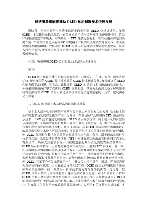
如图1所示,与OLED显示科学技术相比较,液晶显示科学技术最大区别为光源,液晶显示科学技术需背光源提供相应光源,但OLED显示科学技术则无需背光源提供相应光源。
白光,属于液晶显示科学技术背光源,光源经薄膜的晶体管(TFT)来对液晶层内液晶实际排列方式予以有效调节,确保光源能够实现不同程度遮蔽的效果及光亮度有效控制效果。
OLED显示科学技术,无需背光源提供相应光源,只借助TFT实现对于蓝、绿、红有机的半导体层相应电势实施调节操作,依据电势的大小情况对电子及空穴的迁移量实施有效控制,促使不同发光的激子产生,最终有颜色不同像素点形成。
uv打印技术说明

UV打印技术说明1. 简介UV打印技术是一种基于紫外线固化原理的先进打印技术。
它利用紫外线照射在特殊的油墨或涂料上,通过光化学反应使其迅速固化,从而实现高质量、高分辨率的图像打印。
UV打印技术在广告、装饰、印刷等领域具有广泛的应用。
2. 原理UV打印技术的核心原理是紫外线固化。
当紫外线照射到特定的油墨或涂料上时,其中的光敏物质会发生光化学反应,使油墨或涂料迅速固化。
这种固化过程是瞬间完成的,因此可以实现高速打印。
UV打印技术主要分为两个步骤:喷墨和固化。
首先,喷墨系统将油墨喷射到打印材料上,形成图像。
然后,紫外线灯照射在油墨上,使其迅速固化,形成耐磨、耐光的图像。
3. 优势UV打印技术相比传统的喷墨打印技术具有许多优势:3.1 高质量UV打印技术可以实现高分辨率的图像打印,能够呈现出细节丰富、色彩鲜艳的效果。
由于UV固化的特性,图像会立即固定在打印材料上,不会产生模糊或晕染的现象。
3.2 多材料适用UV打印技术可以适用于多种不同的材料,如纸张、塑料、金属、玻璃等。
无论是平面材料还是曲面材料,都可以通过UV打印技术实现高质量的图像打印。
3.3 耐久性由于UV固化的特性,打印出的图像具有较高的耐久性。
UV油墨或涂料固化后形成的图像不易磨损、褪色或受潮,能够长时间保持良好的质量。
3.4 环保UV打印技术使用的油墨或涂料中不含有挥发性有机物,不会产生有害气体释放。
同时,由于UV固化的特性,油墨或涂料不会渗透到打印材料中,减少了对环境的污染。
3.5 高效率UV打印技术具有快速固化的特性,可以实现高速打印。
与传统的喷墨打印技术相比,UV打印速度更快,生产效率更高。
4. 应用领域UV打印技术在许多领域具有广泛的应用:4.1 广告UV打印技术可以实现高质量的广告标识、海报、展板等的制作。
UV固化的特性使得打印出的图像具有良好的耐候性,能够长时间保持鲜艳的色彩。
4.2 装饰UV打印技术可以用于家居装饰、商业空间装饰等领域。
喷墨印刷技术的发展趋势

喷墨印刷技术的发展趋势喷墨印刷技术自20世纪70年代初问世以来,已经成为商业和家庭印刷的主流方式。
作为一种快速、灵活、成本低廉而且质量不错的印刷技术,喷墨印刷技术在最初的几十年里一直保持着稳健发展。
但是随着信息技术和数字化技术的飞速发展,喷墨印刷技术也迎来了全新的发展契机。
本文将对喷墨印刷技术的发展趋势进行分析和探讨。
一、高清晰度和高速度的结合高速喷墨印刷机器的诞生,使得高速印刷成为可能。
CEO of Mark Andy公司Kevin Wilken表示,“我们开始看到一些速度为100米/分钟或更快的喷墨印刷机器,这使得喷墨印刷成为一个快速且多样化的工艺。
”随着印刷机器的速度提高,打印头也需要变得更加灵活和精准。
喷墨印刷头现在变成了可以平移、旋转和调整出墨点大小、精度的运动系统。
不仅如此,更高的分辨率成为这个快速印刷新时代的要求。
Durst、EFI、Xerox等全球领先喷墨印刷供应商正在不断地对印刷头的分辨率和稳定性做出改进。
他们的研发目标是推出具有600dpi甚至更高分辨率的喷墨印刷机。
二、打印效果的多样性喷墨印刷只是一种单色打印技术的过去,现在它拥有着越来越多的色卡。
这些彩色喷墨印刷机可以让设计师用各种鲜艳,时尚而富有创意的颜色搭配创建出独具匠心的作品。
LED染料、单板式液晶(LCD)等新材料的应用,使得喷墨印刷效果更加丰富和细腻。
不仅如此,喷墨印刷现在已经可以实现物料规格从生活照片、家庭贴纸、旅游纪念品到宣传海报、产品标签等各种不同应用场景的应用需求。
为了满足客户的个性化需求,印刷公司可以利用喷墨印刷技术生产自定义的产品以满足客户的需求,从而提高准确度和效率。
三、近距离喷墨印刷近距离喷墨印刷是一种新的应用场景,这种技术利用喷墨头将墨水添加到物体的表面而不是传统的平面印刷。
这个技术可以在一些物资上添加图片,包括塑料、金属、陶瓷、木材等材质。
喷墨式打印机已经被用于定制骨骼,医疗设备、服装、汽车零部件等。
喷墨印刷oled原理-概述说明以及解释

喷墨印刷oled原理-概述说明以及解释1.引言1.1 概述概述部分的内容应该简要介绍喷墨印刷OLED 技术,并提出本文的目的和重要性。
喷墨印刷OLED 技术是一种新兴的显示技术,它结合了OLED(有机发光二极管)和喷墨印刷技术的优势。
OLED 技术具有自发光、视角宽、高对比度等优点,而喷墨印刷技术则具有低成本、高效率、可大面积制造等特点。
喷墨印刷OLED 可以通过喷墨技术将有机发光材料溶液精确地喷射到基板上,形成显示像素,从而实现高质量、高分辨率的显示效果。
本文旨在深入探讨喷墨印刷OLED 的原理和应用。
通过对OLED 技术和喷墨印刷技术进行综合分析,我们将介绍OLED 技术的基本原理以及喷墨印刷技术在OLED 制造中的应用,以期展示喷墨印刷OLED 技术的前景和潜力。
对于读者来说,理解喷墨印刷OLED 的原理和技术应用有着重要意义。
这一新兴技术有望在未来的显示器市场中取得突破,其低成本、高效率和高质量的优势将使其在平板电视、智能手机和可穿戴设备等领域广泛应用。
因此,了解喷墨印刷OLED 的工作原理和特点对于研究人员、工程师和消费者都具有重要的参考价值。
通过本文的研究,我们将为读者提供全面的了解喷墨印刷OLED 技术的基础知识,帮助读者准确评估该技术的前景和应用潜力。
最后,我们将总结OLED 原理的重要性,并对喷墨印刷OLED 技术的未来进行展望。
1.2 文章结构本文主要介绍喷墨印刷OLED的原理。
文章结构如下:第一部分为引言,包括概述、文章结构和目的。
在概述中,将简要介绍OLED的原理和应用;在文章结构中,说明本文将介绍OLED原理和喷墨印刷技术的基本原理及其在OLED制造中的应用;在目的中,阐明本文旨在总结OLED原理的重要性并展望喷墨印刷OLED的前景。
第二部分为正文,分为两个小节。
第一小节将深入介绍OLED原理。
首先,解释什么是OLED,包括其基本概念和原理。
然后,详细介绍喷墨印刷OLED的概念和应用,阐述其在显示技术领域的优势和发展前景。
浅谈数字印刷喷墨油墨及其技术

浅谈数字印刷喷墨油墨及其技术摘要:随着数字印刷市场的不断扩大,数字印刷中的油墨特性也越来越受到关注。
数字印刷中的油墨主要分为碳粉技术和喷墨技术两种,其中喷墨技术在市场上大幅面广告印刷业务中应用广泛。
本文将重点介绍数字喷墨油墨及其技术。
数字喷墨油墨是一种应用于喷墨印刷中的油墨,具有许多优点。
首先,数字喷墨油墨色彩鲜艳,可以在不同的介质上打印出高质量的图像。
其次,该油墨具有极快的干燥速度,可以在短时间内完成印刷任务。
此外,数字喷墨油墨还具有良好的光泽度和耐久性,可以保证印刷品长时间保持鲜艳。
关键词:数字印刷;喷墨油墨;技术1目前喷墨技术的类型1.1连续式喷墨印刷连续式喷墨印刷是一种常见的喷墨技术,但应用其进行印刷作业的企业却并不多。
该技术的优势在于喷射速度极高,并能保证准确到达指定位置。
然而,连续式喷墨的喷墨环节是连续的,其能耗过高且有效能耗利用率过低,同时喷墨墨水在运行过程中利用率也很低,这也是很多厂家放弃这项技术的主要原因。
连续式喷墨印刷技术通过不断喷射墨水来形成图像或文字。
由于其喷射速度极高,因此适用于需要大量印刷的场合,如海报、广告牌、标识等。
此外,连续式喷墨技术还可以应用于定制印刷,如个性化海报、标语等。
然而,连续式喷墨技术的优势也带来了一些局限性。
首先,由于其喷墨环节是连续的,因此能耗过高且有效能耗利用率过低。
这使得连续式喷墨技术在长时间印刷作业中容易产生能源浪费和环境污染。
其次,喷墨墨水在运行过程中利用率低,导致墨水浪费和成本增加。
这也是很多企业放弃这项技术的主要原因之一。
为了克服连续式喷墨印刷技术的局限性,一些企业采用了一些改进措施。
例如,优化墨水配方,减少喷墨墨水的浪费;提高喷头性能,减少喷头故障率;加强设备维护,提高设备寿命和稳定性。
这些措施可以有效提高连续式喷墨印刷技术的利用效率和经济效益。
1.2热发泡式喷墨印刷热发泡式喷墨技术的基本原理是通过加热墨水产生气泡并破裂来形成墨滴。
喷墨应用场景
喷墨应用场景
1. 打印和印刷:喷墨打印机和喷墨印刷机常用于家庭和办公环境,用于打印文档、照片和图像。
喷墨技术提供了高质量、高速度和低成本的打印解决方案。
2. 广告和标识制作:喷墨技术可用于制作广告牌、海报、标志和展览展示品。
喷墨打印机可以在各种材料上打印出高分辨率的图像和文本,适用于户外和室内广告应用。
3. 纺织品印刷:喷墨技术在纺织品印刷领域也有广泛应用,可以在织物上打印图案、图像和设计。
这种应用包括服装印刷、家用纺织品印刷和室内装饰材料的印刷。
4. 包装印刷:喷墨技术可用于印刷包装材料,如纸盒、纸箱和袋子。
它提供了灵活的设计和定制能力,适用于小批量和个性化的包装需求。
5. 建筑和室内设计:喷墨打印机可用于打印大型壁画、壁纸和装饰材料。
这种技术可以实现高精度的图像和颜色还原,为室内设计和建筑装饰提供了更多选择。
6. 工业制造:喷墨技术在工业制造中也有应用,例如在电子产品、汽车和航空航天领域中打印标签、标识和电路图。
7. 艺术和摄影:喷墨技术被艺术家和摄影师广泛用于打印艺术品和照片。
喷墨打印机能够还原细腻的色彩和细节,提供高质量的输出。
总之,喷墨技术的应用场景非常广泛,涵盖了打印、印刷、广告、纺织、包装、建筑等多个领域。
它的灵活性、高质量和低成本使其成为许多行业中受欢迎的技术选择。
《喷墨打印QLED器件制备工艺研究》范文

《喷墨打印QLED器件制备工艺研究》篇一一、引言近年来,QLED(量子点发光二极管)技术因其在显示领域的高效、高分辨率及长寿命等特点,得到了广泛关注。
其中,喷墨打印技术作为QLED器件制备的关键工艺之一,对于提高器件性能和降低成本具有重要意义。
本文将重点研究喷墨打印QLED 器件的制备工艺,以期为相关研究提供参考。
二、文献综述在QLED器件的制备过程中,喷墨打印技术因其高精度、高效率和低成本等优点,被广泛应用于量子点层的制备。
在国内外众多研究中,喷墨打印技术主要分为两种:热喷墨打印和压电喷墨打印。
热喷墨打印技术具有高分辨率和良好均匀性的特点,而压电喷墨打印技术则具有高稳定性和可调性强等优势。
在材料方面,量子点作为QLED器件的核心组成部分,其种类、尺寸和形状等对器件性能具有重要影响。
目前,CdSe、InP 等量子点因其良好的发光性能被广泛用于QLED器件的制备。
同时,对于QLED器件的其他组成部分,如空穴传输层、电子传输层等,也需要根据不同的应用场景进行选择和优化。
三、实验方法本研究采用压电喷墨打印技术制备QLED器件。
首先,将量子点溶液与有机材料进行混合,得到合适的浓度和黏度。
然后,将混合溶液装入喷墨打印机的喷头中,利用计算机控制系统进行图案的精准打印。
最后,通过热处理和封装等工艺完成QLED器件的制备。
四、实验结果与讨论1. 喷墨打印参数的优化通过对喷墨打印速度、喷射频率等参数的调整,实现了对量子点分布和膜层厚度的有效控制。
同时,优化了量子点溶液的浓度和黏度,使得打印得到的膜层更加均匀和致密。
2. 量子点层与其他层的关系在QLED器件中,量子点层与其他层(如空穴传输层、电子传输层等)之间的相互作用对器件性能具有重要影响。
通过调整各层之间的能级匹配和界面修饰等手段,提高了器件的发光效率和稳定性。
3. 性能测试与结果分析通过测试QLED器件的电流-电压特性、发光效率、色度等性能指标,发现采用喷墨打印技术制备的QLED器件具有高亮度和高效率的特点。
喷墨印刷应用状况及发展

喷墨印刷应用状况及发展喷墨印刷是一种通过喷墨喷头将油墨或染料喷射到印刷材料上的印刷方法。
相比传统的印刷技术,喷墨印刷具有以下优势:高效率、低成本、可变数据、高画质、便于个性化定制等。
因此,喷墨印刷被广泛应用于包装、标签、海报、商业印刷、工艺品等行业。
喷墨印刷的应用范围非常广泛。
在包装领域,喷墨印刷可以实现快速切换不同产品的包装信息,提高生产效率。
在标签印刷中,喷墨印刷可以实现定制化标签的生产,满足个性化需求。
在海报和商业印刷领域,喷墨印刷可以实现高品质的印刷效果,增加色彩的丰富度。
在工艺品印刷中,喷墨印刷可以实现对异形材料的印刷,使产品更具个性。
随着技术的不断进步,喷墨印刷正在迎来更广阔的发展前景。
首先,喷墨印刷技术的精度和速度都得到了大幅度的提升,可以满足更高要求的印刷品质和生产效率。
其次,喷墨印刷技术的适应性增强,可以在更多的材料上进行印刷,如塑料、金属、陶瓷等。
此外,喷墨印刷还可以与其他技术相结合,如激光雕刻、热转印等,进一步丰富印刷效果。
喷墨印刷在数字印刷领域发挥着重要的作用。
数字印刷是一种根据需求进行个性化定制的印刷方式,与传统印刷方式相比,数字印刷具有灵活性高、生产周期短等优势。
喷墨印刷作为数字印刷的一种重要形式,可以实现高精度、高速度的印刷效果,满足个性化印刷的需求。
随着个性化消费需求的不断增长,数字印刷市场有望进一步扩大,喷墨印刷也将迎来更广阔的发展机遇。
除了在常规印刷领域的应用,喷墨印刷还在其他领域展示出广阔的应用前景。
在纺织印刷领域,喷墨印刷可以实现对纺织品的图案、花纹等进行印刷,实现个性化的纺织品生产。
在家具、陶瓷等行业,喷墨印刷可以实现对产品表面的多彩印刷,提高产品的附加值。
在建筑装饰领域,喷墨印刷可以实现对墙面、地板、壁纸等的印刷,实现个性化装饰效果。
然而,喷墨印刷仍然存在一些挑战。
首先,喷墨印刷的成本相对较高,在某些应用场景可能难以与传统印刷方式竞争。
其次,喷墨印刷中的油墨和染料对环境可能造成一定的污染,需要进一步提高环保性能。
- 1、下载文档前请自行甄别文档内容的完整性,平台不提供额外的编辑、内容补充、找答案等附加服务。
- 2、"仅部分预览"的文档,不可在线预览部分如存在完整性等问题,可反馈申请退款(可完整预览的文档不适用该条件!)。
- 3、如文档侵犯您的权益,请联系客服反馈,我们会尽快为您处理(人工客服工作时间:9:00-18:30)。
國 立 交 通 大 學光電工程研究所碩 士 論 文噴墨列印技術於彩色濾光片製程之應用Ink-Jet Printing Technology inColor Filter Fabrication研究生: 施佑儒指導教授: 陳皇銘中 華 民 國 九 十 六 年 七 月Ink-Jet Printing Technology inColor Filter Fabrication研究生 : 施 佑 儒 Student: Shin You-Ru指導教授 : 陳 皇 銘 Advisor: Huang-Ming Philip Chen國 立 交 通 大 學光 電 工 程 研 究 所碩 士 論 文A ThesisSubmitted to Institute of Electrical-OpticalCollege of Electrical Engineering and Computer ScienceNational Chiao-Tung Universityin Partial Fulfillment of the Requirementsfor the Degree ofMasterinInstitute of Electrical-OpticalJuly 2007Hsinchu, Taiwan, Republic of China.中 華 民 國 九 十 六 年 七 月研究生: 施佑儒 指導教授: 陳皇銘 博士國立交通大學光電工程研究所摘要近年來,平面顯示器產業技術(LCD、OLED、PDP、FED等)已趨成熟,很多公司及研究單位紛紛投入下一世代顯示器的開發。
彩色濾光片是液晶顯示器的關鍵零組件,目前彩色濾光片以旋轉塗佈法製程為主流,但旋轉塗佈法在成本考量上十分浪費,且其製程步驟繁複、重複。
另外旋轉塗佈法對於下一世代的面板(超大型基板)製程較不適用。
利用噴墨列印技術,可以精確地列印出彩色濾光片所需的紅、綠、藍三原色畫素陣列,並且噴墨列印技術以最少材料、最環保製程製作顯示器的彩色濾光片。
但在利用此項技術上,為防止彩色顏料在噴印過程中,由於墨水高度可能要比黑色矩陣來的高出許多,而因此造成墨水溢流,並且互相混色的情形。
因此本論文根據墨水特性對於黑色矩陣基板做相應的處理,將墨滴在黑色矩陣的接觸角提高,使墨滴黑色矩陣牆上不濕潤,用以避免混色情形在噴墨列印過程中發生。
本論文共使用兩種方法用以使墨滴黑色矩陣牆上不濕潤上,作為參考,並討論其表面特性的改變以及其他效應的產生,進一步說明此二種方法在實際噴塗的應用性。
本論文並且使用顯示科技所財產下的噴墨列印系統,實際進行噴塗,完成紅、綠、藍三色的單色噴塗,並將三色整合噴塗於黑色矩陣基板上,完成擁有紅、綠、藍三原色畫素陣列。
Ink-Jet Printing Technology inColor Filter FabricationStudent: Shin You-Ru Advisor: Dr. Huang-Ming Philip ChenInstitute of Electrical-OpticNational Chiao Tung UniversityAbstractThe color filter (CF) has been one of the most important components for full-color active matrix LCD panel. An emerging process for manufacturing CF has been technically developed by an inkjet printing system. Inkjet printing process for color filter fabrication is key technology for next generation process.To prevent ink overflow from the black matrices (BM) bank, two effective surface treatments are introduced in this thesis. Because the color ink is jetting on glass substrates with black matrices (BM), the total jetting droplet’s volume will overflow from one bank to another if the volume is much larger than the bank. Increase contact angle of drops on BM to make color ink not wetting and to prevent ink overflow from the BM bank. The contact angle of drops on chemical treated and CFx plasma treated BM are increased.In this thesis, we also use the Litrex 70L ink-jet printing system to print red, green, and blue single color films. And we also combined the red, green, and blue color films to form a three-color films BM.誌謝隨著畢業季節的到來,回想兩年來的學習,要感謝非常多的人。
首先要感謝我的指導教授陳皇銘博士,在不管是學業和實驗上,不辭辛勞的給我鼓勵和指導,終有這篇論文的產生,使我受益良多。
另外我更要感謝鄭榮安博士對我的指導,能夠在我的實驗進行不順,而我茫然無知時,給我許多的意見與資源,並能在我毫不熟悉的領域上,給我幫忙和動力,使我從一個無知的小碩一,直至今日能有一些小成果。
另外我也要感謝學弟祥志,幫我分擔了許多實驗上許多瑣碎的事情,也一直陪著我做實驗、搞機台,並且也能在實驗上互相討論,完成此篇論文。
在此我還要感謝實驗室的各位,坤展、威慶、耿睿、俊民、耀慶、佳恬、鴻杰,一起同甘共苦,一起打拼課業,並且能在實驗上,一起討論,還有學長書豪、世民、宜揚陪著我努力、嘻笑,也非常謝謝各位學弟妹,文孚、彣綺、怡帆、謹瑋、蓮馨,幫大家一起做實驗,為這個實驗室貢獻,大家可以說是好夥伴,希望以後也還能常常聯絡。
另外也要感謝工程師林育欣的幫忙,沒有你我們大家也搞不定實驗機台,更要對這些日子來,帶給你的麻煩說聲抱歉。
總之要感謝的人太多太多了,在這裡佑儒對你們致上最高的感謝之意,謝謝。
Table of contentsChinese abstract (i)English abstract (ii)Acknowledgement (iii)Table of contents (iv)List of Figures (vi)List of Tables (ix)Chapter 1 Introduction1.1 Introduction of LCD structure (1)1.2 Color filter of LCD (2)1.3 Color filter conventional fabrication (3)1.4 Introduction of ink-jet printing (4)1.5 Advantage of IJP (7)1.6 IJP in color filter fabrication (7)Chapter 2 Surface treatment2.1 Surface treatment in IJP color filter application (9)2.2 Chemical surface treatment (10)2.3 Plasma surface treatment (11)Chapter 3 Experimentdesign (14)3.1 Experiment3.2 Ink characterizations of IJP (16)3.2.1 Ink property (16)3.2.2 Color film property (18)3.2.3 Color film reliability (19)3.3 BM glass treatment (21)3.3.1 BM glass chemical treatment (21)3.3.2 BM glass plasma treatment (21)3.3.3 Ink contact angle measurement (22)process (23)3.4 Printing3.4.1 Printing pattern design (23)3.4.2 Printing process & maintain (24)Chapter 4 Result & Discussion4.1 Contact angle of BM glass surface treatment (26)4.1.1 Contact angle of BM glass chemical surface treatment (27)4.1.2 Contact angle of BM glass CFx plasma surface treatment304.1.3 Discussion of surface energy344.2 Printed R G B single color film (35)4.2.1 Printed Red single color film (36)4.2.2 Printed Green single color film (38)4.2.3 Printed Blue single color film (40)4.3 Printed R G B color film (41)4.4 Summary (42)Chapter 5 Conclusions & Future Works5.1 Conclusions (44)Works (45)5.2 FutureReferences (46)List of FiguresFig.1.1. Basic structure and components of LCD display panel and its work function (2)Fig.1.2. Color filter structure of RGB color films and BM on the glass substrate (2)Fig.1.3. Color filter conventional fabrication (3)Fig.1.4. Ink-jet printing technology tree (5)Fig.1.5. Thermal bobble print head (6)Fig.1.6. Piezoelectric print head (Shear mode) (6)Fig.2.1. Monolayer chemical formed on the substrate (11)Fig.2.2. Principle of plasma generation using Ar as an example (12)Fig.2.3. Effect of plasma in the chamber (13)Fig.3.1. Litrex 70 ink-jet printer (14)Fig.3.2. Basic structure of ink jet printing system (15)Fig.3.3. The relationship of drop size and drop diameter for a spherical shape drop (16)Fig.3.4. (a) Shear for fluid by Newton (b) BROOKFIELD/U.S.A DV-III+ viscosity measurement instrument (17)Fig.3.5.(a) RGB Color film thickness and roughness (b) UV-visible spectrum of RGB color film (19)Fig.3.6. UV-visible spectrum of RGB color film and CIE1931 color coordinate of chemical resistance tests (20)Fig.3.7. Chemical treatment process (21)Fig.3.8. Plasma treatment process (22)Fig.3.9. Method of contact angle system measurement (a) wetting surface (b) not wetting surface (22)Fig.3.10. Design for one of the three primary color print pattern using Litrex inside program (23)Fig.3.11. Every subpixel are designed to print 7 drops (24)Fig.3.12. The mechanical langrage which is called swath and the printing recipe (24)Fig.3.13. Drops jetting out of the nozzle (a) earlier time of drops jetting out of the nozzle(b) later time of drops jetting out of the nozzle (25)Fig.4.1. Contact angle of water on blank BM (26)Fig.4.2. Contact angle of water on different treatment BM and glass (27)Fig.4.3. Contact angle of red ink drop on blank BM and glass (a) blank BM (b)blank glass (27)Fig.4.4. Contact angles of red ink drops on (a) chemical1 treated BM (b) chemical1 treated glass(c) chemical2 treated BM (d) chemical2 treated glass (28)Fig.4.5. Contact angle of green ink drop on blank BM and glass (a) blank BM (b)blank glass (28)Fig.4.6. Contact angles of green ink drops on (a) chemical1 treated BM (b) chemical1 treated glass(c) chemical2 treated BM (d) chemical2 treated glass (29)Fig.4.7. Contact angle of blue ink drop on blank BM and glass (a) blank BM(b)blank (29)Fig.4.8. Contact angles of blue ink drops on (a) chemical1 treated BM (b) chemical1 treated glass(c) chemical2 treated BM (d) chemical2 treated glass (30)Fig.4.9. Red ink drops on CFx plasma treatment (a) BM side (b) and glass side (31)Fig.4.10. Green ink drops on plasma treatment (a) BM side (b) and glass side (31)Fig.4.11. Blue ink drops on plasma treatment (a) BM side (b) and glass side. (32)Fig.4.12. Height of BM with the treatment time increasing for 0 to 50 seconds (33)Fig.4.13. Contact angles of red ink drops on different time plasma treatment BM (a1) 10s (b1) 20s (c1) 30s and glass (a2) 10s (b2) 20s (c2) 30s (34)Fig.4.14. Drops on chemical treated BM by dip coating (35)Fig.4.15. The printed red color film observed under POM (36)Fig.4.16. The profile of red color film and the thickness of color film are about 0.1 um measuring by α-step (36)Fig.4.17. UV-visible spectrum of single red color film for film thickness 0.1 um (37)Fig.4.18. Different printing times of color film thickness (a) film profile (b) OM picture (37)Fig.4.19. The printed green color film observed under POM (38)Fig.4.20. The profile of green color film and the thickness of color film are about 0.1 um measuring by α-step (39)Fig.4.21. UV-visible spectrum of single green color film for film thickness 0.1 um (39)Fig.4.22. The printed blue color film observed under POM (40)Fig.4.23. The profile of blue color film and the thickness of color film are about 0.2 um measuring by α-step (40)Fig.4.24. UV-visible spectrum of single blue color film for film thickness 0.2 um (41)Fig.4.25. RGB color filter observed under POM (41)Fig.4.26. The profile of RGB color films (42)List of TablesTable.1.1. Compare with ink-jet print and conventional color filter process (8)Table.3.1. Specification of print head (16)Table.3.2. Ink and color film properties (17)Table.4.1. Contact angle of color inks on BM and glass (32)Chapter 1Introduction1.1 Introduction of LCD structureFollowing with the multimedia age, the huge growth of liquid crystal display (LCD) has been exhibited by the vital requirement of market for the application of flat panel display in the field of portable, consumer, and information technology oriented commodities. Small applications include portable devices, such as mobile phones, digital cameras, handheld games, PDAs and GPS. For large applications, LCD technology aggressively fits into all branches, such as laptop screens, monitors, TV and high-definition TV (HDTV). As we know, LCD is combined with the three most important part of light source like CCFL, LED and gray scale control including LC, polarizer, TFT with driver IC and color filter to reach full color display.TFT is used for generating an electric field to control the liquid crystal orientation. The polarized light will have different retardations when passing through the different orientation liquid crystal layer. The gray scale is controlled by using two polarizers and different polarized light for LCD display as shown in Fig. 1.1. Color filter of red, green, and blue subpixel is used for full color LCD display.Fig. 1.1 Basic structure and components of LCD display panel and its work function1.2 Color filter of LCDThe color filter has been one of the most important devices for full-color active matrix LCD panel since it obviously defines the image quality of flat panel display in chromatic characteristics [4][7].Fig. 1.2 Color filter structure of RGB color films and BM on the glass substrateI t is formed by arranging coloring materials on each pixel to selectively transmit the three primary colors (red, green, and blue) of light as shown in Fig. 1.2 [27][28][29]. The dominant applications for color filters are colored display, image sensor of charge coupleddevice and line sensor of crystal shutter [3].1.3 Color filter conventional fabricationVarious color filter production processes have been developed to reduce the cost of the color filter. Two typical color filter production processes are as follows. The first conventional process is a dyeing process. A water-soluble polymer for dyeing is sensitized by adding a photosensitive material. Then, the sensitized polymer is patterned into a desired shape on a transparent substrate by photolithography, and the pattern is dyed in a dyeing bath to produce a colored pattern. This operation is repeated three times to produce a color filter. On the other hand, the second conventional process is a pigment dispersion process [7]. Currently this process is widely used for mass production. A photosensitive resin layer containing a dispersed pigment is formed on a substrate. The resin layer is patterned to obtain the pixel pattern by lithography. This operation is repeated three times to establish an RGB color filter as shown in Fig. 1.3. The above two processes require repeating the same operation three times for the formation of R, G and B pixels, thereby increasing the production cost. Moreover, the yield decreases with increasing number of steps.Fig.1.3 Color filter conventional fabrication1.4 Introduction of ink-jet printingThe earliest development of ink-jet printing was in 1878. After 1951, Siemens Company published a patent of turning ink into drops technology. Year 1964, the volume of drop and printing speed could be controlled by using a special machine; this is the basic mechanism of ink-jet printing. Until to 1967, Hertz Company developed the ink-jet printer of continuous type, it’s now the continuous ink-jet printing technology of industry manufacturing. Year 1972, Siemens Company published piezoelectric type of Drop-on-Demand ink-jet printing. Year 1979, Canon published thermal type of Drop-on-Demand ink-jet printing and made a name of Bubble Ink-jet Printing. Year 1984, HP also published thermal type of Drop-on-Demand ink-jet printing. Those are the history of ink-jet printing technology [9][10].Basically, there are two types of ink-jet printing. First one is continuous type, the others is Drop-on-Demand type. Continuous type is majored in industry manufacturing without high resolution. The advantages of continuous type including high printing speed, smooth of printed surface is not so important. But continuous type has the disadvantage of low resolution. Continuous type ink-jet printing is usually used for printing large playbill, large billboard… etc.Drop-on-Demand type is different from continuous type, the print speed is not so fast but Drop-on-Demand ink-jet printing has very high resolution, though the printed surface would be very flat.There are thermal、piezoelectric、electrostatic、acoustic, four kinds of Drop-on-Demand ink-jet printing type as shown in Fig 1.4. The first tow kinds is principally developed and used [11][12].Fig. 1.4 Ink-jet printing technology treeThermal ink-jet printing is researched and developed by Canon and HP. Piezoelectric ink-jet printing is researched and developed by Epson and Sharp. The thermal ink-jet printing system of HP is using thermal heater heating the ink as shown in Fig 1.5. The ink will be gasified momentarily after heated and become a bobble pushing liquid ink jetting out of the nozzle. The piezoelectric jetting system of HP is using piezoelectric device pushing liquid ink jetting out of the nozzle as shown in Fig 1.6(Shear mode). In the global ink-jet printing market share, HP is the highest about 50%, and Epson is highest in the Taiwan ink-jet printing market share, about 40%, HP is the second about 30%. Canon is not as high as we think in the global or Taiwan ink-jet printing market share though Canon isthe first one inventing bubble ink-jet printing [16][20].Fig. 1.5 Thermal bobble print headFig. 1.6 Piezoelectric print head (Shear mode)Contrast to thermal bobble type, piezoelectric type has the advantages of: will not heat the ink and not to cause damage to inkPiezoelectric has faster response time than thermal bobblePiezoelectricPiezoelectric is easier to control the volume of drops and to improve the resolutionand printing quality.1.5 Advantage of IJPThere are many advantages in ink-jet printing technology. The generally advantages are as follows:1.Additive process to accurately deposit materials in one step and maskless.2.Digital process with the capability to write data and continuously change theoutput.3.Properties of materials will not deteriorate in fabrication process.4.Non-contact method to deposit material.5.Efficiency application of expensive materials.rge area printing for next generation.On the other hand, using ink-jet printing technology would have the advantage of cost down, and suitable for next generation and organic device fabrication [24].1.6 IJP in color filter fabricationAt present, color filters are manufactured by the pigment dispersion method which includes three lithography processes for the red (R) green (G), and blue (B) color resists [1]. The color resist is spin coated onto a substrate, exposed to UV light, and then developed to prepare the colored pixels. The color resist includes curable resins and dispersed color pigments. It became reactive when irradiated by light, and was further cured by heating. The procedure of coating, light exposure, and development steps must be performed three times in order to obtain pixels of the three RGB colors. Therefore, the equipment cost is increased and the yield decreased due to the complexity of the processes. To solve these problems, the ink-jet printing systems and processes were developed for the manufacture of color filters [2][3].Compared with the conventional pigment dispersion method, the ink-jet method is asimplified process that is more environmentally friendly, and requires fewer raw materials.The RGB inks are ejected onto the micro color areas of the color filter, and are fixed by aUV curing reaction. The colored layers of R, G and B can be formed in a single step. This method reduces the process steps and the equipment investment cost. Moreover, the inkscan be deposited selectively on pixel areas without waste [5]. Additionally, productivity canbe improved and production costs can be reduced.Table. 1.1 shows the ink-jet print and conventional color filter process [9].(Generation 3.5 RGB process)Ink-jetPrinting SpincoatingEquipment Only one printing systemNo mask Three mask process equipment Mask (1500~2000 K NT/per)Process FewprocessstepPrinting ink in pixel using only onestep Many process step and complex Using three mask processMaterial >95%Almost no waste <10%About 90% material wasted in spin coating process70% material removed in mask processNext generation Suitable for large area and flexiblesubstrate in next generationCoating for large area substrateis hardTable. 1.1 Compare with ink-jet print and conventional color filter processChapter 2Surface Treatment2.1 Surface treatment in IJP color filter applicationAn emerging process for manufacturing color filter has been technically developed by an inkjet printing system. The piezoelectric printing head has been innovated as the emerging tool for fabricating large-sized color filter, organic thin-film transistor devices, flexible display, and organic light emitting diode in mass production. However, literature on the manufacturing of color filter by inkjet printing technique is very few [3]. From the economical viewpoints of competition in production, inkjet printing is a high efficiency technology for resist-saving and low-cost productivity in the processing of large size panels [5][6].Generally speaking, there is an issue for color filter printing process that color ink overflows when printing. To solve this problem, many methods of preventing ink overflowing are published and used for ink-jet printing color filter process. The common method is to use rib building on BM, but it needs mask process. Here, we use surface treatment as a method to block ink overflowing and the surface treatment uses only one step process.Different surface treatments of the substrate resulted in different performances of hydrophobic and hydrophilic effect [13]. Use chemical coating and plasma surface treating astwo kinds of surface treatment for hydrophobic treatment. Color ink would not be wetting on hydrophobic treatment thus the color ink would be blocked in subpixels without overflowing when printing [14][15].2.2 Chemical surface treatmentThe black matrices were coated with a monolayer and the surface became hydrophobic and the surface energy was changed due to the monolayer chemicals. The monolayer chemical contains the chemical compound of fluorine as shown. Chemical 1:R(X)SiOMe3Where R is alkyl containing fluoridesX is spacer with the alkyl groupFig. 2.1 shows the monolayer chemical formed on the substrate. The process includes coating chemical on substrate and baking. After monolayer chemical is formed, the surface of substrate will show a hydrophobic property because of the R alkyl containing fluorides. A simple process is provided to form a hydrophobic surface for preventing color ink overflowing.R(X)Si(OMe)3H 2OMeOHR(X)SiO(OH)3H O2Si O O HOH Si OH (X)R O (X)R Si (X)R OHOHOH OH OH Substrate H O2heatSi O O H OSi O (X)R O (X)R Si (X)R O OHSubstrateFig. 2.1 Monolayer chemical formed on the substrate2.3 Plasma surface treatmentPlasma treatment is a common surface treatment to form a hydrophobic or hydrophilic surface. Different plasma has different effect. Plasma is named by Irvin Langmuir in 1929; and plasma is partial ionized gases which can be define as a quasi-neutral ga s of charged &neutral particles characterized by a collective behavior. Fig. 2.2 shows the principle of plasma generation using Ar as an example.Fig. 2.2 Principle of plasma generation using Ar as an exampleThe Kinetic Energy is the energy for plasma generation as shown in 2.2.1.(Kinetic Energy) gained = F.d = q.ε.λ = q.(V/de).λ. (2.2.1)where λ:mean free path ; de:electrode distanceε:electric field ; V:electrode voltageDifferent plasma has different effect. CFx plasma is a common method for chemical stability, low surface energy, low refractive index, good electrical and thermal insulation applications. For the purpose to prevent color ink overflowing, here we use CFx plasma as a surface treatment to decrease surface energy and to increase contact angle.Fig. 2.3 shows the effect of plasma in the chamber. When we treat the BM substrate, other effect would influence the results. The etching effect of CFx plasma would be an issue when we using a CFx plasma surface treatment.Fig. 2.3 Effect of plasma in the chamberChapter 3Experiment3.1 Experiment designThe ink-jet printer Litrex 70 as shown in Fig. 9 is used for printing R,G,B color film.Fig. 3.1 Litrex 70 ink-jet printerThe system of inkjet printing equipment includes the glass substrate laying on the X-Y table, main system monitor for observation and measurement, drop-on-demand printing head,ink storage syringe, ink supply system, controller and printing head driver for ink injection, shown in Fig.3.2. The ink droplets are injected through the orifice of printing head and dropped in the substrate. The compatibility between color photoresists and printing head should be the main bottleneck issue due to di ff erent ingredients and properties of color ink and piezoelectric material of printing head [16][19].Fig. 3.2 Basic structure of ink jet printing systemThe ink-jet printing equipment is a Drop-On-Demand type printer. Print head is Spectrum piezoelectric head [17][18]. Distance between nozzle and nozzle is about 507 um and nozzle diameter is 38 um. Drops size are about 25 to 35 pl which depend on ink property and applied printing voltage. The specification of print head is shown in table 3.1. The relationship of drop size and drop diameter is shown in Fig. 3.3. Drop diameter of 25 to 35 pL droplet are about 58 to 66 um.24262830323436585960616263646566D r o pD i a m e t e r (u m )Drop Size (pL)Fig. 3.3 The relationship of drop size and drop diameter for a spherical shape dropTable. 3.1 Specification of print head Print Head typeSpectra SE-128Addressable Jets 128 Drop size (pL) 25-35 Fluid viscosity range (cP)8-20Nozzle diameter (um)383.2 Ink characterizations of IJPFor insuring the inks we used are in the specification of printing system and testing the color quality of color film, ink and color film properties are measured [28~32].3.2.1 Ink propertyTable 3.2 shows the viscosity and surface tension of ink. Viscosities of red, green, andblue inks are 11.07, 7.23, and 12.99 cp. Surface tensions are 28.2, 28.0, and 28.1. The optimal viscosity for SE-128 print head is within 8 to 20 cp that the color inks are usable.Table. 3.2 Ink and color film propertiesInk Viscosity(@ 25o C; Cp)Surface tension(@ 25o C ;mN/m)Film thickness(um)CIE1931x yRed 11.07 28.2 1.80 0.663 0.330Green 7.23 28.0 1.80 0.313 0.610Blue 12.99 28.1 2.00 0.130 0.126*Solid contain: 20 – 23 %The optimal viscosity for SE-128 print head is within 8-20 Cp.The viscosities are measured by BROOKFIELD/U.S.A DV-III+ viscosity measurement instrument. Basic theory of the viscosity measurement instrument are shownin Fig. 3.4(a) (b)Fig. 3.4 (a) shear for fluid by Newton (b) BROOKFIELD/U.S.A DV-III+ viscosity measurement instrumentBROOKFIELD/U.S.A DV-III+ viscosity measurement instrument uses spindle spinning in the measured material and measures the torque when spindle is spinning as shown in Fig. 3.4(b).Fig. 3.4(a) shows the shear for fluid proposed by Newton. Tow parallel fluid surfacesin different plane has the same area of A, and the distance between the two different parallel fluid surfaces is dx. The two different parallel fluid surfaces flow in the same direction with different flowing speed. We will have an equation of:F/A = ηdv/dxη is viscosity and dv/dx is shear rate which means the shear of fluid. The unit of shear rate is sec-1. F/A term which called shear stress means the shearing force of fluid in per unit area. The unit of shear stress is dyne/cm2. We will have an equation of:η = (F/A) / (dv/dx) = shear stress / shear rateThe unit of viscosity is cp or mPa․s.1 cp = 1 mPa․s3.2.2 Color film propertyColor films are formed by spin coating method. After color films are formed, they were soft baked by 90o C for 10 minutes, cured by UV light for 250 mj/cm2, and hard baked by 230o C for 40 minutes.Fig. 3.5(a) shows the color film thickness and roughness which is measured by AFM (Atomic Force Microscope). The thickness of red, green, and blue color films are 1.81, 1.80, and 2.00 um and the roughness are 9.628, 9.294, and 8.071 nm.Fig. 3.5(b) shows UV-visible spectrum of RGB color films of thickness shown in Fig.3.5(a). The CIE1931 color coordinate of RGB color films are x = 0.663, y = 0330, for red color film and x = 0313, y =0610, for green color film, and x = 0.130, y =0.126, for blue color film after turning UV-visible spectrum of RGB color film to CIE1931 color coordinate [25][26].(a)(b)Fig. 3.5 (a) RGB Color film thickness and roughness (b) UV-visible spectrum of RGB color film3.2.3 Color film reliabilityThe reliability of color film is used for insuring that chemical resistance of color film. Color filter is combined with other components to form a display. The reliability of color film relates to the quality of color filter.Chemical resistance tests are using different solvent for testing as shown in Fig. 3.6. Color films are dipped into chemicals for 24 hrs.Blue (2.00 um)40050060070020406080100T (%)Wavelength (nm)R e dG r e e nB l u eGreen (1.80 um)Red (1.81 um)Ra: 9.628 nmRa: 9.294 nmRa: 8.071 nm(a)(b)Fig. 3.6 UV-visible spectrum of RGB color film and CIE1931 color coordinate of chemical resistance tests1931 CIEx,y CoordinationsRedGreenBlueOriginal (0.580, 0.318)(0.352, 0.491)(0.161, 0.242) Methanol (0.580, 0.317)(0.351, 0.498)(0.167, 0.245) Ethanol (0.566, 0.316)(0.352, 0.470)(0.161, 0.239)1931 CIEx,y CoordinationsChemicals Red Green Blue NTSCOriginal (0.655, 0.330)(0.300, 0.621)(0.133, 0.101) 74 % IPA (0.659, 0.330)(0.303, 0.617)(0.134, 0.108) 73 % PGMEA(0.660, 0.329)(0.310, 0.611)(0.132, 0.104) 72 %r-butyrolatane (0.664, 0.329)(0.307, 0.613)(0.133, 0.113) 72 %T (%)Wavelength (nm)Blank Methanol EthanolRedGreenBlueT (%)Wavelength (nm)IPA PGMEAr-butyrolatane。