阿法拉伐无菌取样阀中文版
阿尔法拉瓦尔 SB 膜样品抽取阀门操作手册说明书
Alfa Laval SB Membrane Sampling Valve
ESE02963-EN6
Original manual
2022-10
Table of contents
The information herein is correct at the time of issue but may be subject to change without prior notice
Designation
SB Membrane Sample Valve
Type
is in conformity with the following directives with amendments: - The Supply of Machinery (Safety) Regulations 2008
The person authorised to compile the technical file is the signer of this document.
Global Product Quality Manager
Title
Kolding, Denmark
Place
2022–10–01
Date (YYYY-MM-DD)
Signature
5
2 Safety
Unsafe practices and other important information are emphasised in this manual. Warnings are emphasised by means of special symbols.
2.1. Important information ............................................................................. 6 2.2. Warning signs ..................................................................................... 6 2.3. Safety precautions ................................................................................ 7 3. Installation .................................................................................... 8 3.1. Unpacking/delivery ............................................................................... 8 3.2. General installation ................................................................................ 8 3.3. Valve assembly .................................................................................... 9 3.4. Recycling information ............................................................................. 11 4. Operation ..................................................................................... 12 4.1. Operation .......................................................................................... 12 4.2. Sterilisation with alcohol .......................................................................... 13 4.3. Sterilisation with steam ........................................................................... 14 4.4. Sampling ........................................................................................... 15 5. Maintenance .................................................................................. 17 5.1. General maintenance ............................................................................. 17 6. Technical Data ............................................................................... 21 6.1. Technical data ..................................................................................... 21 7. Parts List and Service Kits ................................................................... 22 7.1. Membrane Sampling Valve, manual ............................................................ 22 7.2. Membrane Sampling Valve, manual & micro port ............................................. 24 7.3. Membrane Sampling Valve, pneumatic ......................................................... 26
阿尔法拉維(Alfa Laval)水泥阀门(Valves)维护指南说明书
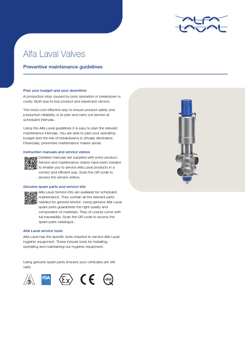
Detailed manuals are supplied with every product.Service and maintenance videos have been createdto enable you to service Alfa Laval products in acorrect and efficient way. Scan the QR code toaccess the service videos.Genuine spare parts and service kitsAlfa Laval Service Kits are available for scheduledmaintenance. They contain all the relevant partsneeded for general service. Using genuine Alfa Lavalspare parts guarantees the right quality andcomposition of materials. They of course come withfull traceability. Scan the QR code to access thespare parts catalogue.Alfa Laval service toolsAlfa Laval has the specific tools required to service Alfa Laval hygienic equipment. These include tools for installing, operating and maintaining our hygienic equipment.Using genuine spare parts ensures your certicates are still valid.Example of exploded view - Unique MixproofCut-away views ofthe plug and seatdesign in Uniquemixproof valves.Closed OpenCoverFlushing tubewith o-ringLip sealO-ringLowervalve plugSeal ringClamp ringValve bodyPTFE guide ringPTFEguide ringUppervalve plugUpper sealingelementLip seal O-ringClamp ringSpraynozzle(spiral clean)O-ringO-ringLockClampFlushing tubewith o-ringSpindle linerClampActuatorNozzleDrainLower sealingelementInspect the valves regularlyThe Alfa Laval valves are available in various con figurations to fit speci fic applications. To inspect the valves you need to know the type of valves and which seals are used. This information can be obtained online by using the serial number no which along with year of manufacturing is laser marked on to the actuator. Preventive maintenance aims to prevent failure of equipment by doing e.g. regular inspection of seals, lubrication and/or adjustments of surrounding equipment without prior knowledge of equipment failure. Based on experience and knowledge about the running conditions, it is also possible to replace wear parts before they fail. Keeping a record of the valve is a good way to build experience for inspection planning.This Preventive Maintenance Guideline is applicable to most types of valves. Below are show some examples:Mixproof valves Single seat valves Butter y valvesRegulating valves Ball valves SafetyvalvesSamplevalvesShuttervalvesDiaphragmvalves UniqueMixproofSMP-BCAsepticMixproofUniqueMixproofTank OutletUniqueSSVUnique SSVTank OutletLKAPAir-OperatedLKB LKBUltraPureLKB-FUniqueRV-STUniqueRV-PCPM-2SBV Sanitary Unique SamplingValveMH Shutter Unique DV-STUltraPureSafety ValveSuggested scheduled maintenance intervalsSeveral factors in fluence the maintenance cycle. The number of activations is important but even with few activations the rubber materials will harden over time and need replacement. The time depends on the product contents, concentration and type of CIP, SIP, differential pressure and processing temperatures. To ensure that your valves operate efficiently, it is essential to follow a simple preventive maintenance programme. Good maintenance requires careful attention at regular intervals. For lubrication please always refer to the manual for specific information on oil/grease types and required maintenance. Alfa Laval recommend:•Always carefully follow the instruction manual for the speci fic valve.•Lubricate relevant rubber parts with the lubricant supplied with the service kit before fitting.•Service kit for valves actuator parts: Replace after 5 years or depending on working conditions.•Service kit for valves product wetted parts: Replace every 12 months or depending on working conditions.•Service kit for Unique sampling valves: Replace after 500-1000 samples depending on working conditionsThe guidelines may not apply in all working conditions. Please contact Alfa Laval for information relating to specific applications.This document and its contents are subject to copyrights and other intellectual property rights owned by Alfa Laval AB (publ) or any of its affiliates (jointly “Alfa Laval”). No part of this document may be copied, re-produced or transmitted in any form or by any means, or for any purpose, without Alfa Laval’s prior express written permission. Information and services provided in this document are made as a benefit and service to the user, and no representations or warranties are made about the accuracy or suitability of this information and these services for any purpose. All rights are reserved.200008519-1-EN-GB© Alfa Laval How to contact Alfa LavalUp-to-date Alfa Laval contact details for all countries are always availableon our website at 。
阿尔法拉瓦尔Unique SSV ATEX标准单座阀门说明书
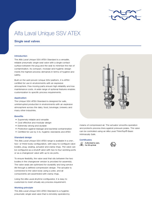
•Cost effective and modular design •Extremely strong and durable•Protection against leakage and bacterial contamination •Certified for use by 3-A, hygienic standards and ATEXStandard designThe Alfa Laval Unique SSV ATEX range is available in a one-,two- or three-body configuration, with easy-to-configure valve bodies, plug, sealing, actuator and clamp rings. The valve can be configured as a shutoff valve with two to four working ports or as a changeover valve with up to six ports.To ensure flexibility, the valve seat that sits between the two bodies in the changeover version is provided for assembly.The valve seals are optimized for durability and long service life through a defined compression design. The actuator is connected to the valve body using a yoke, and all components are assembled with clamp ing the Alfa Laval Anytime configurator, it is easy to customize to meet virtually any process requirement.Working principleThe Alfa Laval Unique SSV ATEX Standard is a hygienic pneumatic single seat valve that is remotely operated bymeans of compressed air. The actuator smooths operation and protects process lines against pressure peaks. The valve can be controlled using an Alfa Laval ThinkTop® Basic Intrinsically Safe.CertificatesTECHNICAL DATAAmbient temperature:10 °C to +40 °CMin. product pressure:Full vacuumAir pressure, actuator:500 to 700 kPa (5 to 7 bar)1 This equipment is outside the scope of the directive 2014/34/EU and must not carry a separate CE marking according to the directive as the equipment has no own ignition sourceValve Body Combinations2200-0179200300210220310320Actuator function•Pneumatic downward movement, spring return •Pneumatic upward movement, spring return•Pneumatic upward and downward movement A/A PHYSICAL DATAOther steel parts:1.4301 (304)External surface finish:Semi-bright (blasted)Internal surface finish:Bright (polished), Ra < 0.8 µm)Product wetted seals:EPDM Other seals:NBRActuator stem:PAGG PAGI/GT, MH, 14-250, CF40Spring:Coated steelOptions •Male parts or clamp liners in accordance with required standard •Control and Indication: ThinkTop Basic Intrinsically Safe•Product wetted seals in HNBR or FPM (Note! Temperature range 10 °C to +135 °C for ATEX Versions)•Plug seals in HNBR or FPM (Note! Temperature range 10 °C to +135 °C for ATEX Versions)•External surface finish brightNote! For further details, see instruction manual ESE00674.Other valves in the same basic designThe Unique SSV valve range includes several purpose built valves. Below are some of the valve models available,though please use the Alfa Laval Anytime configurator for full access to all models and options.•Reverse acting valve •Tank Outlet valve •Tangential valveSemi-Maintainable actuator comes with 5 year warranty.Dimensions (mm)Figure 1. Shut-off valveFigure 2. Change-over valve1313314363389422467315315365389427470A 2 1328334388414452497330335390414457500A 3 136023744364755215913672379440.6481534596A 4 137223914584975486183792396463503561623C 47.860.873.886.398.9123.652647692107126OD 25385163.576.1101.62941537085104ID 21.834.847.860.372.997.62638506681100t 1.6 1.6 1.6 1.6 1.62 1.5 1.5 1.5222E 5049.56181861195049.5627887120F 1152025253030152025253030F 212217222227271221722222727H8585ø115ø115ø155ø1558585ø115ø115ø155ø155H (high pressure)85ø115ø155ø155ø155ø15585ø115ø155ø155ø155ø155M (ISO clamp)212121212121------M (DIN clamp)------212121282828M (DIN male)------222223252530M (SMS male)202020242435------Weight (kg)Shut-off valve3.1 3.3 5.5 6.511.313.6 3.2 3.4 5.5 6.611.813.6Change-over valve3.94.27.18.514184.14.57.28.814.917.91 For exact A1 - A4 dimensions, please refer to information in Anytime configurator.2 Only available with replaceable elastomer plug seal.Note!Opening/closing time will be effected by the following:•The air supply (air pressure)•The length and dimensions of the air hoses•Number of valves connected to the same air hose•Use of single solenoid valve for serial connected air actuator functions •Product pressureAir Connections Compressed air:R 1/8" (BSP), internal thread.Size DN/OD 25-38 mm DN/OD 51-63.5 mm DN/OD 76.1-101.6 mm NO and NC 0.2 x air pressure [bar]0.5 x air pressure [bar] 1.3 x air pressure [bar]A/A0.5 x air pressure [bar]1.1 x air pressure [bar]2.7 x air pressure [bar]Pressure drop/capacity diagrams Change-over ValvesChange-over ValvesQ (m³/h)A = DN25/25 Kv 15B = DN40/38 Kv 34C = DN50/51 Kv 64D = DN65/63.5 Kv 128E = DN80/76.1 Kv 179F = DN100/101.6 Kv 227A B102030405060708090100110120Q (m³/h)A = DN25/25 Kv 11B = DN40/38 Kv 27C = DN50/51 Kv 51D = DN65/63.5 Kv 72E = DN80/76.1 Kv 106F = DN100/101.6 Kv 191P (kPa)Shut-off Valves00102030405060708090100110120Q (m³/h)A = DN25/25 Kv 14B = DN40/38 Kv 29C = DN50/51 Kv 56D = DN65/63.5 Kv 94E = DN80/76.1 Kv 166F = DN100/101.6 Kv 238AP (kPa)403020100102030405060708090100110120Q (m³/h)A = DN25/25 Kv 15B = DN40/38 Kv 40C = DN50/51 Kv 80D = DN65/63.5 Kv 131E = DN80/76.1 Kv 186F = DN100/101.6 Kv 257BP (kPa)100110Q (m³/h)A = DN25/25 Kv 12B = DN40/38 Kv 26C = DN50/51 Kv 50D = DN65/63.5 Kv 86E = DN80/76.1 Kv 128F = DN100/101.6 Kv 185P (kPa)Q (m³/h)A = DN25/25 Kv 15B = DN40/38 Kv 34C = DN50/51 Kv 70D = DN65/63.5 Kv 111E = DN80/76.1 Kv 177F = DN100/101.6 Kv 256ABNote!For the diagrams the following applies:Medium: Water (20°C)Measurement: In accordance with VDI2173Pressure drop can also be calculated in Anytime configuratorPressure drop can also be calculated with the following formula:Q = Kv x √ΔpWhereQ = Flow in m3/h.Kv = m3/h at a pressure drop of 1 bar (see table above).Δ p = Pressure drop in bar over the valve.How to calculate the pressure drop for an ISO 2.5" shut-off valve if the flow is 40 m3/h 2.5" shut-off valve, where Kv = 111 (See table above).Q = Kv x √Δp40 = 111 x √Δp0.13 bar(This is approx. the same pressure drop by reading the y-axis above) Pressure data for Unique Single Seat ATEX ValveFigure 3. 1Figure 4. 2Figure 5. 3Figure 6. 4Figure 7. 5Figure 8. 6Figure 4. 259.2 4.4 5.9 3.4 4.4 2.9 6NO10.07.69.6 5.67.2 4.8 710.010.010.07.810.0 6.7Figure 5. 3510.0 5.7 6.8 3.7 4.7 3.0 6NC10.09.810.0 6.17.7 5.0 710.010.010.08.510.0 6.9Figure 6. 4NC10.0 6.37.2 4.2 6.4 4.2Figure 7. 5510.010.010.010.010.09.4 6A/A10.010.010.010.010.010.0 710.010.010.010.010.010.0Figure 8. 6510.010.010.010.010.09.1 6A/A10.010.010.010.010.010.0 710.010.010.010.010.010.0Figure 9. 7Figure 10. 8Figure 11. 9Figure 12. 10Figure 10. 8510.07.810.0 6.17.1 4.7 6NO10.010.010.08.39.9 6.6 710.010.010.010.010.08.5Figure 11. 9510.010.0 6.8 6.67.5 4.9 6NC10.010.010.09.010.0 6.9 710.010.010.010.010.08.8Figure 12. 10NC10.09.710.0 6.89.1 6.1This document and its contents are subject to copyrights and other intellectual property rights owned by Alfa Laval Corporate AB. No part of this document may be copied, re-produced or transmitted in any form or by any means, or for any purpose, without Alfa Laval Corporate AB’s prior express written permission. Information and services provided in this document are made as a benefit and service to the user, and no representations or warranties are made about the accuracy or suitability of this information and these services for any purpose. All rights are reserved.200004003-2-EN-GB© Alfa Laval Corporate AB How to contact Alfa LavalUp-to-date Alfa Laval contact details for all countries are always availableon our website at 。
阿法拉伐换热器的操作手册中文版

序言
中文
PHE 的储存
如果未就其他任何事项达成一致,则阿法拉伐交付的 PHE 在到货时即可投入使用。但是,安装之前,请 将 PHE 保留在包装箱中。
如果要储存较长的时间 (一个月或以上),应采取一 定的防范措施,以避免对 PHE 造成不必要的损坏。
注意!
在合同规定的保修截止日期之前,阿法拉伐及其代表保 留在必要时对储存空间和 / 或设备进行检查的权利,但 需要提前 10 天发出检查通知。
安全注意事项
PHE 图纸
本手册中提到的 PHE 图纸是指交付板式换热器时包 括在内的图纸。
应按照本手册中的阿法拉伐指导说明使用和维护板式 换热器。 板式换热器的操作不当可能会导致严重的后 果以及人员伤害和 / 或财产损坏。阿法拉伐对因未遵 循本手册中的说明而导致的任何损失或伤害不负任何 责任。
应按照特定板式换热器的材料、介质类型、温度和压 力的规定配置使用板式换热器。
SL CS
LV
LT
ET
EL
BG
RO
ZS
XX
ZH
板式换热器
1644725-02 修订版 2009-11
SK HU EN
SL CS
LV
说明
主要组件
框架板
压紧板
说明
螺栓保护装置
支柱
中文
拧紧螺栓
接口孔 带双头螺栓接口
承载杆
防护罩
导杆
板片组
管道接口
螺栓保护装置 承载杆 框架板 导杆 管道接口
板片组
带双头螺栓接口的 接口孔 压紧板 防护罩 支柱 拧紧螺栓
操作 ...................................................................................................... 9
阿法拉伐中文说明书

阿法拉伐中文说明书1(共94页) -本页仅作为预览文档封面,使用时请删除本页-目录1安全说明…………………………………………………………..... 2卧螺离心机的操作原理……………………………………….....主电机………..…………………………………………….………………......后驱动系统……………..………………………………………………… ...变频后驱动(VFD)..…….……………………………………………… ..... 3操作和日常维护…………………………………………………在第一次开车前……………..………………………………………………噪声和振动…………...……...………………………………………….…开车和停车程序…………………..…………………………………………检查转鼓……..…………………………………………………………….开车前…………..………………………………………………………….检查要点………….……………….……………………………………..具有机械密封的离心机…………………..……………………………..启动离心机………………………………………..……………………….离心机停车……………………………………………..………………….监控操作……………………………………………………………………..过载………………………………………………………………………...过载的原因………………………………………………………………清理过载的转鼓…………………………………………………………振动………………………………………………………………………... ..振动开关(可选设备)…………………………………………………监测螺旋磨损……………………………………………………………...定期清洗过程………………………………………………………………..优化操作……………………………………………………………………..主电机………………………………………………………………………..变频驱(VFD)……………………………………………………………...调整转鼓速度传感器(图)………………………………………..润滑…………………………………………………………………………..主轴承……………………………...………………………………………螺旋轴承(图中的加油嘴3和4)………………………………...齿轮箱(图)………………………………………………………...维护表……………………………...…………………………………………润滑时间和维护方法……………………………………………………...表润滑表………………………………………………………….…表维护周期…………………………………………………………润滑剂型号………………………………………………………………...表润滑剂、润滑工具表……………………………………………4拆卸和组装………………………………………………………旋转组件……………………………………………………………………...拆卸转鼓(图和)…………………………………………….安装转鼓(图和)…………………………………………….拆卸大端轴颈(图)………………………………………………...安装大端轴颈(图)………………………………………………...拆卸小端轴颈(图)………………………………………………...安装小端轴颈(图)……………………………………………….拆卸齿轮箱(图和)………………………………………….安装齿轮箱(图和)…………………………………………装配新的排污口衬套…………………….………………………………主轴承…………….…………………………………………………………..拆卸大端主轴承(图)…………………………………….…………..组装大端主轴承(图)………………………………………………...拆卸小端主轴承(图)………………………………………………...安装小端主轴承(图)………………………………………………...螺旋轴承……………………………………………………….…….……….拆卸螺旋大端轴承(图)…………………………………….………..组装螺旋轴承大端轴承(图)………………………………………拆卸螺旋轴承小端轴承(图)……………………………………...安装螺旋轴承小端轴承(图)……………………………………...螺旋…………………………………………………………………………...从转鼓中拆卸螺旋(图)……………………………………………将螺旋装入转鼓(图)………………………………………………...主电机………………………………………………………………………..拆卸主电机(图)……………………………………………….…..组装主电机(图,和)………………………………….…..调紧V形皮带,皮带张力表………………………………………………变频后驱动装置(VFD)…………………….……………………………..拆卸变频驱动器(图)………….………………………………….组装变频驱动器(图)……………………………………………..5补充文档…………………………………………………………1安全说明请务必严格按照以下要求进行操作,否则会给您造成人员以及财产的损失。
阿尔法拉夫Unique DV-ST超纯洁膜片阀门说明说明书

regulationsStandard designThe Alfa Laval Unique DV-ST UltraPure diaphragm valve has a modular design that consists of a valve body, diaphragm, and either a handle for manual operation or an actuator for pneumatic operation. It can be designed to suit any application.The actuator is standard in Stainless steel execution and available in two versions. A HighPressure version (SS/HP) and a Slim (SS/SL) version for std. duties. Both versions are available in either Normally Closed (NC), Normally Open (NO) or an Air/Air (A/A) activated solution. Futhermore also ATEX compliant and autoclaveable.The DV-ST UltraPure diaphragm valve can be fitted with sensing and control units from an extensive range. Options include control units that suit AS-Interface, IO-Link and digital operating platforms.The diaphragms are available as soft elastomer (EPDM) as well as hard elastomers (PTFE/EPDM and TFM/EPDM).Alfa Laval DV-ST UltraPure valve bodies are available in cast, forged, and block options to suit the most demanding applications. A choice of surface finishes and connection types are also available. For critical applications with corrosive media, special alloys such as Hastelloy, duplex, and AL-6XN materials in block design are available upon request. Working principleThe Alfa Laval Unique DV-ST UltraPure Diaphragm Valve has two modes of operation: manual operation by means of a handle and pneumatic operation by means of a pneumatic actuator.For manual operation, a simple turn of the handle lifts the compressor upwards, moving the diaphragm away from the weir of the valve body thereby opening the valve. Turning the handle in the opposite direction pushes the compressor downwards onto the diaphragm, pressing the diaphragm against the weir of the valve body, thereby closing the valve. For pneumatic operation, the pneumatic actuator controls the axial movement of a piston, thereby opening or closing the valve depending on the actuator function.Valve Body DesignThe valve bodies are available in a wide variety of valve types and configuration options (dimension standards, connections, surface finish and material).•2-way body•T-body (Zero dead-leg design)•Tank outlet body•Tandem body / IAV solutions•Multi-port bodyConfigurator available.Figure 1. 2–way Figure 2. T-Block Figure 3. Multi-port Figure 4. Tandem Figure 5. Tank outlet-blockPHYSICAL DATAMaterialsT✓Tank outlet✓Tandem / IAV solutions✓✓✓Multi-port✓1 Other alloys on request.Delta ferrite< 5.0%< 0.5%< 0.5%Sulphur content0.005%-0.017%0.005-0.017%0.005-0.017%Internal surface finish Ra < 0.51 µmRa < 0.38 µm EP 1Ra < 0.51 µmRa < 0.38 µm EP 1Ra < 0.51 µmRa < 0.38 µm EP 1External surface finish Blasted Blasted Machined1 Electro Polished0.51µm = SF1, 0.38 µm = SF4Sensing and control units:A wide range of sensing and control units are available for actuators consisting of:•Controls unit•Indication units•ATEX units•Stroke limiters - Only for SS/SL Slim actuatorsUnique DV-ST SS/HP HighPressure version actuator DN8-15 (1/4"-1/2")Adapter for mounting of ThinkTop V50, ThinkTop Basic, ThinkTop D30 and IndiTop - see automation accessoriesUnique DV-ST SS/SL Slim version actuatorAll sizes require adaptor for mounting of Sensing & Control solutions - see automation accessoriesDocumentationAll UltraPure valves are delivered with our comprehensive Q-Doc documentation package, which includes:•3.1/ MTR traceability certificate corresponding to EN 10204•FDA - Declaration of conformity to FDA (CFR 21: 177.2600 or 177.1550)•USP - Certificate of conformity to USP Class VI (Chapter 88, biological reactivity test)•TSE/ADI - Declaration (Transmissible Spongiform Encephalopathy/Animal Derived Ingredients)•Cure date of diaphragms•Surface finish conformity declarationThe following documentation is available upon request:•Surface finish certificate (Ra test results)•ATEX certificateHandle and actuator:The diaphragm valves can be operated by a handle or pneumatic actuator. Alfa Laval offers 2 versions of manual handles and 2 versions of pneumatic actuator.Figure 6. Model SS/SL Figure 7. ModelSS/HP SizesDN 8 - 1001/4” - 4”Housing Stainless steelIntermediate part Stainless steelCompressor, stem Stainless steelFull Vacuum✓Leakage Detection✓Autoclavable 1✓Max. Air Temperature80°CMax. Air Pressure 27 barStroke limiter Yes NoOD Surface Polished Blasted Valve/Seat tightness ANSI Class VI ANSI Class VI ATEX✓II 2G Ex h IIB T4 Gb (-10°C ≤ tamb ≤ 80°C)II 3D Ex h IIIB T100°C Dc (-10°C ≤ tamb ≤ 80°C)Max working pressure Delta P 100% 3Delta P 0% 3 Sizes¼” – 1½”EPDM 10 bar Sizes¼” – 4"EPDM 10 barPTFE/EPDM 6 bar PTFE/EPDM 10 barTFM/EPDM 6 bar2”-4”EPDM 8 barPTFE/EPDM 5 bar1 121°C for max. 60 min2 Min. Air pressure see instruction manual3See figures below for Delta P 100% and Delta P 0%Figure 8. Delta P 100%Figure 9. Delta P 0%Figure 10. Model SS/SSFigure 11. Model C/SSSizeDN 8 - 1001/4” - 4”DN 8 - 1001/4” - 4”Handwheel Stainless steel PA 1BonnetStainless steel Stainless steel Spindle + compressor 1 Stainless steel Stainless steel Max. product pressure 10 bar 10 bar Overclosure protection ✓ ✓Optical positioner ✓✓Autoclavable ✓2 ✓2Leakage Detection ✓✓Valve/Seat tightness ANSI Class VIANSI Class VI ATEXII 2 G D 3 3 Stroke limiterOptionalOptionalNote! The stroke limiter manual handles, max opening per size as below:DN8/10 100%DN15 50%DN20 40%DN25 65%DN40 75%DN50 90%DN65 100%DN80 100%1 PA (polyamid)2 121°C for max. 60 min.3 This equipment is outside the scope of the directive 2014/34/EU and must not carry a separate CE marking according to the directive as the equipment has no own ignition sourceDiaphragmsThe diaphragms are available as soft elastomer (EPDM) as well as hard elastomers (PTFE/EPDM and TFM/EPDM).The hard elastomers are supported by a soft elastomer (EPDM). The 2-piece design allows the two elastomers to work independently of each other, thereby reducing tension caused by different thermal properties.Diaphragms are available with 3 different types of connections: thread, bayonet and button connection.•Threaded connections are used on soft elastomers ≥ DN 25 (1")•Bayonet connections are used on all hard elastomer ≥ DN 15 (1/2")•Button connections are used on all small sizes.Material selection:Each application has different working conditions and therefore different demands on the diaphragm. In order to select the most suitable diaphragm for your application, the following factors should be considered:•Working pressure•Application temperatures•Process fluids (product, cleaning liquid, sterilisation, passivation, etc.)Soft elastomer (EPDM) is suitable for most applications and for high working temperatures. Including continuous steam application.Hard elastomers offer the highest possible degree of chemical resistance. Our TFM (PFTE grade) elastomer is a more flexible material and has some of the features of soft elastomer including for example low creep.For further information, please see below or contact Alfa Laval for further guidance.Diaphragm properties:✓✓✓DN 8 - 100DN 8 - 20DN 25 - 100PTFE/EPDM -5°C 175°C 150°C 4✓✓✓DN 15 - 100 DN 15 - 100TFM/EPDM-5°C175°C150°C 4✓✓✓DN 8 - 100DN 8 - 10DN 15 - 1001 < DN25 thread optional2 TFM/EPDM point-fixed thread optional3 Continuous temperature4 40 min. steam sterilisationFDA - Declaration of conformity to FDA (CFR 21: 177.2600 or 177.1550)USP - Certificate of conformity to USP Class VI (chapter 88, biological reactivity test)TSE/ADI Declaration (Transmissible Spongiform Encephalopathy /Animal Derived Ingredients)Alfa Laval Cast valve bodies with Optimized Flow utilize smaller diaphragm and topwork vs. Valve pipe dimension. Topwork being either pneumatic or manual. This giving the benefit of having a slim and light weight valve.Correct spare parts are easy to identify via the diaphragm tab, stating the giving size of diaphragm and topwork to be used on the valve. See image belowMaterial codediaphragm materialCure datematerialDiaphragm materialMaterial codePressure drop/capacity tableKv value (Pipe standard ISO 1127 / DIN/A), Forged and BlockKv value (Pipe standard ASME BPE), Forged and BlockKV Value Cast bodies Optimized Flow (OP)KV Value (Pipe standard ASME BPE / ISO 2037 Cast OP)0.22.25.110.825.353.479.7128.6KV values are based on lab test.Drain angle x:Drain angles, forged and block valve bodies10⅜”33°25°35°28°15½”35°26°24°20°20¾”34°30°28°23°251”29°29°25°21°321¼”--18°26°40 1 ½”30°29°27°22°502”25°24°24°20°65 2 ½”23°23°20°16°803”26°27°23°22°1004”14°14°13°8°Drain angles, forged mini valve bodies10⅜”30°15½”26°Drain angles, Cast OP valve bodies203/4”20°14°251”22.7°22°4011/2”13.8°13°652"1/2”14.7°15°803”14.9°15°Dimensions (mm)2-way body:2-way bodies are the standard configuration for shut off and regulating functions.The 2-way bodies are available from forged or cast material.The cast bodies feature a unique Optimized Flow design (OP) providing optimization on diaphragm and topworks being applied on the valve.See futher in the DV-ST catalogue.10⅜”899.53 x 0.8912.70 x 1.0013.00 x 1.5017.20 x 1.6015½”8912.70 x 1.6515½”11012.70 x 1.6517.20 x 1.0019.00 x 1.5021.30 x 1.6020¾”11919.05 x 1.6521.30 x 1.0023.00 x 1.5026.90 x 1.60251”12925.40 x 1.6525.00 x 1.2029.00 x 1.5033.70 x 2.00321¼”129--35.00 x 1.50321¼”161---42.40 x 2.0040 1 ½”16138.10 x 1.6538.00 x 1.2041.00 x 1.5048.30 x 2.00502”19250.80 x 1.6551.00 x 1.2053.00 x 1.5060.30 x 2.0065 2 ½”21863.50 x 1.6563.50 x 1.6070.00 x 2.0076.10 x 2.00803”25676.20 x 1.6576.10 x 1.6085.00 x 2.0088.90 x 2.301004”218101.60 x 2.11101.60 x 2.00104.00 x 2.00114.30 x 2.301 Forged onlyBuild-in length of weld/clamp valve bodies: Weld ends L/2 + CL ends L/2 = total length of valve body.10⅜”8963.525.007.7534.0010.7034.0010.001 Forged only2 Standard build-in length acc. EN 558-1, Series 73 ASME BPE forged valves only, short version acc. to ASME BPE dimension table for hygienic clamp joint: Weir style diaphragm valve10⅜”10825.014.015½”1088925.009.4034.0015.2034.0016.0050.518.120¾”11810225.0015.7534.0019.3034.0020.0050.523.7251”12711450.5022.1050.5022.6050.5026.0050.529.73211/4”127 50.5032.00 3211/4”15964.038.4401½”15914050.5034.8050.5035.6050.5038.0064.044.3502”19115964.0047.5064.0048.6064.0050.0077.556.31652½”21619477.5060.2077.5060.3091.0066.0091.072.1803”25422291.0072.9091.0072.90106.0081.00106.084.31004"305-118.9297.38119.0097.60119.00100.00119.00109.71 Forged only2 Standard build-in length acc. EN 558-1, Series 73ASME BPE forged valves only, short version acc. to ASME BPE dimension table for hygienic clamp joint: Weir style diaphragm valveBuild-in length of weld/clamp valve bodies: Weld ends L/2 + CL ends L/2 = total length of valve body.Other sizes and connections available on request.T - body:T are constructed with weir as close as possible to the internal contour of the main tube thereby minimising potential dead leg.The T - bodies are available as machined from block. T valve can furthermore be made with steam or sample port solutions. See futher in the DV-ST catalogue.108ø9.53x0.89ø6.35x0.8935.648.3 3.257.082.4158ø12.7x1.65ø6.35x0.8937.049.7 4.681.0106.4208ø19.05x1.65ø6.35x0.8939.952.69.081.0106.4258ø25.4x1.65ø6.35x0.8943.255.912.381.0106.4408ø38.1x1.65ø6.35x0.8955.468.113.081.0106.4508ø50.8x1.65ø6.35x0.8957.770.419.481.0106.4658ø63.5x1.65ø6.35x0.8963.576.225.881.0106.4808ø76.2x1.65ø6.35x0.8970.288.932.181.0106.4 1010ø9.53x0.89ø9.53x0.8935.648.3 3.257.082.41510ø12.7x1.65ø9.53x0.8937.049.7 4.681.0106.4 2010ø19.05x1.65ø9.53x0.8939.952.69.081.0106.4 2510ø25.4x1.65ø9.53x0.8943.255.912.381.0106.4 4010ø38.1x1.65ø9.53x0.8955.468.113.081.0106.4 5010ø50.8x1.65ø9.53x0.8957.770.419.481.0106.4 6510ø63.5x1.65ø9.53x0.8969.576.225.881.0106.4 8010ø76.2x1.65ø9.53x0.8970.282.932.181.0106.4 1515ø12.7x1.65ø12.7x1.6557.770.4 3.695.0120.4 2015ø19.05x1.65ø12.7x1.6558.671.38.095.0120.4 2515ø25.4x1.65ø12.7x1.6562.074.711.395.0120.4 4015ø38.1x1.65ø12.7x1.6568.681.316.9595.0120.4 5015ø50.8x1.65ø12.7x1.6575.287.920.695.0120.4 6515ø63.5x1.65ø12.7x1.6581.894.524.7595.0120.4 8015ø76.2x1.65ø12.7x1.6588.3101.029.195.0120.4 2020ø19.05x1.65ø19.05x1.6564.977.6 1.0109.0134.4 2520ø25.4x1.65ø19.05x1.6568.481.1 6.3109.0134.4 4020ø38.1x1.65ø19.05x1.6575.187.813.0109.0134.4 5020ø50.8x1.65ø19.05x1.6581.794.417.6109.0134.4 6520ø63.5x1.65ø19.05x1.6588.2100.921.2109.0134.4 8020ø76.2x1.65ø19.05x1.6594.8107.524.9109.0134.4 2525ø25.4x1.65ø25.4x1.6572.985.6 4.3117.0142.4 4025ø38.1x1.65ø25.4x1.6579.692.312.4117.0142.4 5025ø50.8x1.65ø25.4x1.6585.398.018.1117.0142.4 6525ø63.5x1.65ø25.4x1.6591.9104.622.2117.0142.4 8025ø76.2x1.65ø25.4x1.6598.4111.125.9117.0142.4 4040ø38.1x1.65ø38.1x1.6588.9101.6 2.4143.0168.4 5040ø50.8x1.65ø38.1x1.6595.8108.511.3143.0168.4 6540ø63.5x1.65ø38.1x1.65102.4115.117.6143.0168.4 8040ø76.2x1.65ø38.1x1.65109.1121.822.6143.0168.4 5050ø50.8x1.65ø50.8x1.65111.5124.2 4.6170.0195.4 6550ø63.5x1.65ø50.8x1.65111.7124.412.8170.0195.4 8050ø76.2x1.65ø50.8x1.65118.4131.118.9170.0195.4 6565ø63.5x1.65ø63.5x1.65134.4147.112.7190.0215.4 8065ø76.2x1.65ø63.5x1.65134.5147.212.9190.0215.4 8080ø76.2x1.65ø76.2x1.65152.1164.89.9233.0258.4Note! Contact Alfa Laval for 4" T-block valves.T-block valves are available in all dimension standards (ASME, DIN, ISO2037, ISO1127) Hybrid solutions with mixed dimension standards (ASME, DIN, ISO2037, ISO1127) is furthermore possible, please contact Alfa Laval.Tank outlet body:Tank outlet bodies with minimised dead leg and complete drainability. The tank outlet valve bodies are available as machined from block. Tank outlet valves can furthermore be supplied with steam or sample port. See futher in the DV-ST catalogue.Dimension table for Tank outlet-block bodies - all standardsDN20 (3/4")100 5.4144°DN25 (1")120 5.4144°DN40 (1½")150 5.4144°DN50 (2")180 5.4144°DN65 (2½")200 5.4144°DN80 (3")250 5.4144°For OD dimensions see two-way valves.Note! Contact Alfa Laval for 4" T-block valves.Tandem body:Tandem solutions are available in a wide variety of angles and positions for sampling, steam, condensate drain or divert function. Tandem solutions can be made in a welded two valve construction or as an Integral Acess Valves block solution (IAV). See futher in the DV-ST catalogue.Tandem body configurationTo configure the tandem body the position and the angle of the two bodies are selected by combining one of the letters with one of the numbers in the following overview.A 132510-0094E F D B C A2.D2.E2B2.C2.F2C1.F1D1.E1Forged Tandem Valves configurations (sizes)DN15 (1/2") X X X X X X DN20 (3/4") X X X X X X DN25 (1") X X X X DN40 (1½") X X DN50 (2") DN65 (2½")DN80 (3")Note! For other size configurations please contact Alfa LavalMulti-port body:Multi-port bodies are a space and time saving alternative to valve clusters minimising dead volumes. Alfa Laval offers customised solutions for both simple and complex processes.For more details, please contact Alfa Laval.This document and its contents are subject to copyrights and other intellectual property rights owned by Alfa Laval AB (publ) or any of its affiliates (jointly “Alfa Laval”). No part of this document may be copied, re-produced or transmitted in any form or by any means, or for any purpose, without Alfa Laval’s prior express written permission. Information and services provided in this document are made as a benefit and service to the user, and no representations or warranties are made about the accuracy or suitability of this information and these services for any purpose. All rights are reserved.200003960-6-EN-GB© Alfa Laval How to contact Alfa LavalUp-to-date Alfa Laval contact details for all countries are always availableon our website at 。
阿尔法拉瓦尔Unique RV-P调节阀门说明说明书

actuator is fitted to the valve body by means of a clamp. The Kv value is flexible as lower element can be exchanged.Manual and aseptic versions are available. Upon request, the valve can also be supplied with a normally closed (NC)actuator.Working principleThe Alfa Laval Unique RV-P Regulating Valve is controlled from a remote location by means of compressed air. An actuator with an integrated IP converter IP convertertransforms the electrical signal to a pneumatic signal. This signal conversion is based on a highly accurate and reliable contactless AMR sensor, making it insensitive to vibrations and pressure shocks. The pneumatic signal is transmitted to the integrated positioner which operates by means of the force-balance principle, ensuring that the position of the actuator piston is directly proportional to the input signal.Signal range and zero point can be adjusted individually. The actuator can be used for split-range operation by using a different measuring spring.CertificatesTECHNICAL DATAMin. product pressure:Full vacuumTemperature range:-10 °C to 140 °C (EPDM)Flow range Kv (Δ P = 1bar):0.5 to 110 m3/hMax. pressure drop:500 kPa (5 bar)Max. pressure:600 kPa (6 bar)Working pressure:400 kPa (4 bar)Max. size of particles:0.01 mmMax. oil content:0.08 ppmDew point:10 °C below ambient temp. or lowerMax. water content:7.5 g/kgInput resistance:200 ΩInductivity/capacitance:NegligiblePHYSICAL DATAOther steel parts: 1.4301(304)Product wetted seals:EPDMExternal finish:Semi-bright (blasted)Internal finish:Bright (polished) RA<0.8 µmDiaphragms:NBR with reinforced fabric insertSprings:Stainless steel uncovered/spring steel epoxy resin coatedActuator stem:PolyamideScrews, nuts:Stainless steel, polyamideOther parts:Stainless steelValve body combinations64-542200300AccuracyDeviation:≤1.5%Hysteresis:≤0.5%Sensitivity:<0.1%Influence of air supply pressure:≤0.1% between 1.4 and 6 barAir consumption at steady state condition:With 0.6 bar signal pressure and supply pressures up to 6 bar ≤100 In/h Ambient temperature:-25 °C to +70 °CProtection class:IP 66Flow sizes/tube connections1.0 E1038403277-52 E1238403277-5 4 E1438403277-5 8 E2338403277-5 16 E2938403277-5 25 E3851503277-5 32 E48.551503277-5 40 E4263.5653277-5 64 L5163.5653277-5 75 L5176.1803277-5110 L72101.61003277-5Options•Male parts or clamp liners in accordance with required standard•Product wetted seals of HNBR or Fluorinated rubber (FPM)•Profibus communication•Aseptic configuration Max 8 barA- aseptic411426412446470488414427418454472490 E566367859696576470899898 G49.561818611911949.5627887120120 H168168168168168280168168168168168280 OD385163.576.1101.6101.641537085104104 ID34.847.860.372.997.697.638506681100100 t 1.6 1.6 1.6 1.622 1.5 1.52222M/ISO clamp212121212121------M/DIN clamp------212128282828 M/DIN male------222325253030 M/SMS male202024243535------Weight kg8.29.39.711.215.424.98.29.39.711.215.424.9Capacity diagram For Δ P= 100 kPa (1bar).Figure 1. StandardFigure 2. Aseptic*Recommended working areaNote! For the diagram the following applies:Medium: Water (20 °C).Measurement: In accordance with VDI 2173.Alfa Laval recommend max. flow velocity in tubing and valves to be 5 m/sec.Conversion Table 100 kPa = 1 bar = 14.5 PSI 10 mm = 0.39 inch 10 m 3/h = 44.03 US GPM Pressure drop calculationThe Kv designation is the flow rate in m 3/h at a pressure drop of 1 bar when the valve is fully open (water at 20°C or similar liquids). To select the Kv value it is necessary to calculate the Kv q value using the following formula:Where:Kv q = Kv value at specific flow and specific pressure drop Q = Flow rate (m 3/h)Δ P = Pressure drop over valve (bar)Electrical connectionElectrical connection - Analogue 4-20 mA Positioner 37252405-0035Cable gland Cover240500362405-0037Terminal screws4-20 mA control signalRoute the two-wire line to the screw terminals marked “11 and 12”, whereby the correct polarity has to be ensured 1.Open the cover of the positioner for electrical connection2.Fit the cable through the cable gland and connect the cable wires to the terminal screws. (+11 and -12)3.Tighten the cable gland and close the cover of the positioner Electrical connection - Profibus PA Positioner 3730-42405-0035Cable gland Cover2405-00382405-0039Terminal screwsBus control signalRoute the two-wire bus line to the screw terminals marked “IEC 1158-2”, whereby no polarity has to be observed 1.Open the cover of the positioner for electrical connection2.Fit the bus cable through the cable gland and connect the cable wires to the terminal screws. (IEC 1158-2)3.Tighten the cable gland and close the cover of the positionerBy searching on positioner type 3730-4 you can either retrieve the GSD files for PROFIBUS PA communication directly from the World Wide Web server of Samson or the PROFIBUS User OrganizationThis document and its contents are subject to copyrights and other intellectual property rights owned by Alfa Laval Corporate AB. No part of this document may be copied, re-produced or transmitted in any form or by any means, or for any purpose, without Alfa Laval Corporate AB’s prior express written permission. Information and services provided in this document are made as a benefit and service to the user, and no representations or warranties are made about the accuracy or suitability of this information and these services for any purpose. All rights are reserved.200003961-1-EN-GB© Alfa Laval Corporate AB How to contact Alfa LavalUp-to-date Alfa Laval contact details for all countries are always availableon our website at 。
阿尔法拉夫安全阀说明书

12 bar. The valve can be operated either pneumatically or manually. It is delivered with PED certificate and complies with PED 2014/68/EU and EN 4126-1, fluid group II (non-hazardous fluids). It is available for pressure regulation of both liquids and gases. Please note that manual pressure regulation of gases has a reduced pressure range.Working principleThe Alfa Laval Safety Valve prevents inadmissible overpressures of fluids in tanks, containers and plant sections. It is factory-configured with the specified set pressure that is greater than the operating pressure. If the operating pressure rises above the set pressure, the valve opens against the spring force to relieve pressure.The valve should be installed in a vertical position for optimal performance. If mounted in a horizontal position, the set pressure will be somewhat lower than specified due to the lack of weight from the piston. The highest effect is obtained using DN80 and DN100.TECHNICAL DATAMax. sterilisation temperature, dry steam:140 °C (Max 30 min)PHYSICAL DATAOther steel parts: 1.4301 (304)Seals:EPDMExternal finish:Ra 1.5-2.5 µm Internal finish:Ra 0.8 µmConnections:Inlet: Liner/nut DIN 11851Outlet: Male DIN 11851Option:Inductive sensor for feedback is available for standard and pneumatic lifting - see instruction manual for detail.Dimensions (mm)Figure 1. Standard DN25Figure 2. Standard DN40-DN100Figure 3. Standard DN25with inductive sensor for feedbackFigure 4. Standard DN40-DN100 with inductive sensor for feedbackDN403238Rd65x1/6Rd65x1/6688225566 9.1DN503850Rd78x1/6Rd78x1/6709330166 1.3DN655066Rd95x1/6Rd95x1/68510540266 15.0DN806681Rd110x1/4Rd110x1/4100115407.566 22.0DN10081100Rd130x1/4Rd130x1/41301304186628.2DN403238Rd65x1/6Rd65x1/66882255663389.1DN503850Rd78x1/6Rd78x1/6709330166384 1.3DN655066Rd95x1/6Rd95x1/6851054026648415.0DN806681Rd110x1/4Rd110x1/4100115407.56648922.0DN10081100Rd130x1/4Rd130x1/41301304186650128.2Figure 5. Manual lifting DN25Figure 6. Manual lifting DN40-DN100Figure 7. Pneumatic lifting DN25 with inductive sensor for feedbackFigure 8. Pneumatic lifting DN40-DN100 with inductive sensor for feedbackDN403238Rd65x1/6Rd65x1/66882255152-232 10.3DN503850Rd78x1/6Rd78x1/67093301154-234 15.5DN655066Rd95x1/6Rd95x1/685105402153-233 16.2DN806681Rd110x1/4Rd110x1/4100115407.5152.5-232.5 23.2DN10081100Rd130x1/4Rd130x1/4130130418152-23229.6DN403238Rd65x1/6Rd65x1/66882255663389.1DN503850Rd78x1/6Rd78x1/6709330166384 1.3DN655066Rd95x1/6Rd95x1/6851054026648415DN806681Rd110x1/4Rd110x1/4100115407.56648922DN10081100Rd130x1/4Rd130x1/41301304186650128.2Opening and closing characteristics for incompressible fluids (Liquid)Max. operating pressure (P over )0.90.80.20 (1 atm)Set pressure (P set )Closing pressure (P close )P (bar)Max. operating pressure (P over ):10 % of set pressure or 0.1 bar, whichever is the greater.Closing pressure (P close ):Maximum 20% or 0.6 bar below set pressure, whichever is the greater.(Example: Set pressure = 0.8 bar)Opening and closing characteristics for compressible fluids (Gas)Max. operating pressure (P over )0.90.80.50 (1 atm)Set pressure (P set )Closing pressure (P close )P (bar)Max. operating pressure (P over ):10 % of set pressure or 0.1 bar, whichever is the greater.Closing pressure (P close ):Maximum 15% or 0.3 bar below set pressure, whichever is the greater.(Example: Set pressure = 0.8 bar)Blow-off performance chart2001-0060051015202530354045Set pressure (bar)Pressure range [bar]A = 0.5 - 1.5B = 1.6 - 2.5C = 2.6 - 4.5D = 4.6 - 7.0E = 7.1 - 12.0123456789101112ABEDCFlow rate [m³/h]Figure 9. DN25 set pressure: 0.2 - 12.0 bar for liquids (water 20 °C)2001-00802505007501,0001,2501,5001,7502,000Flow rate [m³/h]Set pressure (bar)Pressure range [bar]A = 0.2 - 1.5B = 1.6 - 2.5C = 2.6 - 4.5D = 4.6 - 7E = 7.1 - 120123456789101112ACEBDFigure 10. DN 25 set pressure: 0.2 - 12 bar for gases (air 20 °C)Note!DN25 for gas application up to 1,5 bar fulfills the DIN4126-1 requirements. For higher pressures the valve is approved by TÜV .ABDC2001-0062Pressure range [bar]A = 0.2 - 1.0B = 1.1 - 3.0 C = 3.1 - 7.0D = 7.1 - 12.0510152025303540455055012345678910111260Set pressure (bar)Flow rate [m³/h]Figure 11. DN 40 set pressure: 0.2 - 12.0 bar for liquids (water 20 °C)025********,0001,2501,5001,7502,0002,2502,5002,7500123456789101112ABDC2001-0063Set pressure (bar)Pressure range [bar]A = 0.2 - 1.0B = 1.1 - 3.0C = 3.1 - 7.0D = 7.1 - 12.0Flow rate [m³/h]Figure 12. DN 40 set pressure: 0.2 - 12.0 bar for gases (air 20 °C)1234567891011120102030405060708090100110ABEDC2001-0064Set pressure (bar)Pressure range [bar]A = 0.3 - 0.9B = 1.0 - 1.7C = 1.8 - 2.9D = 3.0 - 6.0E = 6.1 - 12.0Flow rate [m³/h]Figure 13. DN 50 set pressure: 0.3 - 12.0 bar for liquids (water 20 °C)012345 6 78910111205001,0001,5002,0002,5003,0003,5004,0004,500A BEDC2001-0065Set pressure (bar)Pressure range [bar]A = 0.3 - 0.9B = 1.0 - 1.7C = 1.8 - 2.9D = 3.0 - 6.0E = 6.1 - 12.0Figure 14. DN50 set pressure: 0.3 - 12.0 bar for gases (air 20 °C)010********60708090100110120130140150160170180012345 6789A BDC2001-0066Set pressure (bar)Flow rate [m³/h]Pressure range [bar]A = 0.4 - 1.5B = 1.5 - 3.0C = 3.1 - 7.0D = 7.1 - 9.0Figure 15. DN65 set pressure: 0.4 - 9.0 bar for liquids (water 20 °C)5001,0001,5002,0002,5003,0003,5004,0004,5005,0005,5006,0006,5007,0007,500012345 6789ABDC2001-0067Set pressure (bar)Flow rate [m³/h]Pressure range [bar]A = 0.4 - 1.5B = 1.5 - 3.0C = 3.1 - 7.0D = 7.1 - 9.0Figure 16. DN65 set pressure: 0.4 - 9.0 bar for gases (air 20 °C)Pressure range [bar]A = 0.3 - 0.9B = 1.0 - 1.9C = 2.0 - 3.3D = 3.4 - 4.3E = 4.4 - 8.0020406080100120140160180200220240260280012345 6 787.56.55.54.53.52.51.50.5A B DC 2001-0068ESet pressure (bar)Figure 17. DN80 set pressure: 0.3 - 8.0 bar for liquids (water 20 °C)5001,0001,5002,0002,5003,0003,5004,0004,5005,0005,5006,0006,5007,0007,5008,0008,5009,000012345 6 787.56.55.54.53.52.51.50.5ABDC2001-0069ESet pressure (bar)Pressure range [bar]A = 0.3 - 0.9B = 1.0 - 1.9C = 2.0 - 3.3D = 3.4 - 4.3E = 4.4 - 8.0Flow rate [m³/h]Figure 18. DN80 set pressure: 0.3 - 8.0 bar for gases (air 20 °C)02040608010012014016018020022001232.51.50.5ABC2001-0070Set pressure (bar)Pressure range [bar]A = 0.3 - 1.1B = 1.2 - 1.8C = 1.9 - 3.2Flow rate [m³/h]Figure 19. DN100 set pressure: 0.3 - 3.2 bar for liquids (water 20 °C)5001,0001,5002,0002,5003,0003,5004,0004,5005,0005,5006,00001232.51.50.5ABC2001-0071Set pressure (bar)Pressure range [bar]A = 0.3 - 1.1B = 1.2 - 1.8C = 1.9 - 3.2Figure 20. DN100 set pressure: 0.3 - 3.2 bar for gases (air 20 °C)This document and its contents are subject to copyrights and other intellectual property rights owned by Alfa Laval Corporate AB. No part of this document may be copied, re-produced or transmitted in any form or by any means, or for any purpose, without Alfa Laval Corporate AB’s prior express written permission. Information and services provided in this document are made as a benefit and service to the user, and no representations or warranties are made about the accuracy or suitability of this information and these services for any purpose. All rights are reserved.200003950-2-EN-GB© Alfa Laval Corporate ABHow to contact Alfa LavalUp-to-date Alfa Laval contact details for all countries are always available on our website at 。
- 1、下载文档前请自行甄别文档内容的完整性,平台不提供额外的编辑、内容补充、找答案等附加服务。
- 2、"仅部分预览"的文档,不可在线预览部分如存在完整性等问题,可反馈申请退款(可完整预览的文档不适用该条件!)。
- 3、如文档侵犯您的权益,请联系客服反馈,我们会尽快为您处理(人工客服工作时间:9:00-18:30)。
及冰激凌等。
Keofitt无菌取样阀
W9型阀门可配备有微型接口,以便用户能够使用皮下注射用针
头进行取样操作。
接式连接端口,也有卡箍式连接端口或带螺纹式的端口。
阀体:
T型:适用于罐体连接(焊接式)。
P型:适用于管道连接(焊接式)。
C型:卡箍式。
S型:插口式(带螺纹)。
阀门头
H型:转动把手。
a.开启阀门,取样
K型:钥匙。
N型:气动式。
该款型阀门已经得到授权可以使用3A标记。
b.关闭阀门,灭菌消毒操作
图1工作原理
尺寸(mm)
阀门位置M4W9
A7090
B49
C58 D(罐体)2828
D(管道)25或2825或28
D(卡箍)2550
(1/2"卡箍)(1"卡箍) D(插口)M28x1.5M28x1.5
E4768
材料
阀体:.................不锈钢,1.4404(316L)
阀头:.................不锈钢,301,303,316L
薄膜:.................硅橡胶(标准型阀门用)
EPDM橡胶(带微型接口的阀
门用)
技术数据
压力
阀座上最大.............
工作压力(关闭阀门):........600kPa(6巴)
阀盖上最大.............
工作压力(开启阀门):........橡胶材料:1200kPa(12巴)
不锈钢材料:1500kPa(15
巴)
温度
最大灭菌消毒温度,干蒸汽(2-3巴):121-134℃。
蒸汽务必是干的,因为冷凝水会损坏薄膜。
我们向用户建议,每100次取样操
作或灭菌消毒操作之后,应该更换薄膜片,或者也可以根据工作条件或经验进行更换。
Valve粘度
M40-100cP
W90-1000
cP W150-50000cP
W250-250000cP 可选项
A.
阀头的钥匙链,型号K。
B.用于进行气动操作的阀门头,型号N(“A”尺寸要放大)。
C.阀头,型号H及K,带微型接口,用于W9型。
D.阀头,型号B(阻断型)不带弹簧,可在出现压力冲击(手柄为红
色)危险的情况下使用产品订购
用户在订购时,请说明以下事项:
-阀门规格,M4型或者是W9型。
-
阀体型号。
-阀头型号。
-附属元器件。
-其他可选项要求。
注意!
有关进一步详情,请参阅指导手册IM70783。
W6及W8型阀门,只有
在用户提出特殊要求时,才可供货。
图3规格
阀体:阀头:
图3.阀体和阀头(可互换)。
ESE00296ZH0801。