
外文翻译原文
Application of Pro/E Behavioral Modeling Technology in Optimization Design for Food Packaging MachinerySongbai Ma, Qiao Bai, and Chunsheng TaoMaterial and Mechanical Engineering School,Beijing Technology and Business University,100048 Beijing, Chinamasongbai@Abstract. Basing on the Pro/Engineer’s behavior modeling module, taking thecommon planar four-bar linkage mechanism as research object, then describedthe application of Pro/E behavioral modeling technology in the aspects ofbehavioral modeling, kinematics and dynamics analysis etc., Thus proves that themethod improves design qualities and efficiencies dramatically, also enriches thefood packaging machinery optimization design methods and provides acompletely new view for which.Keywords: Pro/Engineer behavior modeling technology, planar four-barlinkage, optimization design.Planar four-bar linkage mechanism is widely used in food packaging machinery field, such as sealing machine, packaging machine, and step transporting machine etc., which could easily accomplish given motion law or movement trajectory reconstruction, finish given motion or movement, accomplish some complex motion requirements. Nevertheless, to its design, generally, graphic method or analysis method were used in traditional design, with shortcomings of tedious design process, blindly cut and try method, long design period, poor reliability, all these lead extremely low design precision and efficiency, further can not satisfy the design requirements of modern machinery in high speed and high precision.Here adopts Pro/E behavioral modeling technology to solve and complete optimization design of one dual-purpose vacuum packaging machine and furthest implement the visualization of design process.1 Introduction of Pro/E Behavioral Modeling Technology Behavioral modeling module is one of extend function modules of Pro/Engineering software of PTC(the product development company), aims at helping engineers use this software to make intelligent design and find the optimal scheme. Meanwhile, as a parametric design analysis tool, under the premise of specific design intention and design constraint, can provide the optimal advice for designers after a series of test parameters iterative computation.416 S. Ma, Q. Bai, and C. Tao1.1 The Characteristics of Behavioral ModelingThree features that it has: intelligent model, goal-driven design and opening extensible environment. Intelligent model is able to obtain all engineering standard that relates to one production needs to be defined and designed, such knowledge as geometry dimension, specification, design intention etc.; Goal-driven design has the capability of automatic optimization to solve mutual contradicted goal problems in traditional design, also is capable of acquiring the optimal resolution scheme even under the limitations of multiple design parameters, constraints, design standard, and so on. Engineers can concentrate on designing products with more high performance and more multiple functions by its assistance. Behavioral modeling technology needs an opening extensible environment, which makes behavioral modeling bilateral communicates with external application software easily, meanwhile, ensuring automatically reflecting results from design model, thereby providing coherence for complete design , strengthening the flexibility of design.1.2 Analysis Design Procedures of Behavioral ModelingAs fig.1 ShowsFig. 1. The analysis design procedures of behavioral modeling(1) Features AnalysisFeatures analysis is one type of methods of datum features analysis, aims to analysis the flexible parameters or design optimization. Analysis the physic features of model, curve characteristics of model, curved surface characteristics of mode etc., all these are key step before implementing behavioral modeling.(2) Sensitivity AnalysisThere are two aims to execute sensitivity analysis: one is to determine which parameters are important from numerous design parameters, the other is to further determine the variation range of the related parameters applied to optimization design. Which outcome is a coordinate graph, the abscissa represents dimension variables, and ordinate represents the variation situation of model corresponding to dimension variables. This coordinate graph can be outputted as a format of Excel or chart. InApplication of Pro/E Behavioral Modeling Technology 417 addition, in order to dynamic display variation situation of model corresponding to thechanging process of dimension variables, also the whole process of sensitivity analysiscan be expressed with the animation, so as to let designer knows which dimensionsexits obvious relevance with design goal in a short time.(3) Feasibility/Optimization AnalysisOne shortcoming of sensitivity analysis is just able to change one size or parameter,also is not able to change the model automatically. So if there are more than oneparameter needs to be changed, usually have to by feasibility/optimization analysismethod. This method can make system calculate some special dimension values, and these values could make model satisfy some given constraints by designer, then findout the feasibly optimal resolution scheme from them. The difference betweenfeasibility and optimization is as flows: feasibility research actually is to analyses ifthere is possible for model to reach goal parameter value in given variables range; to themodel involves multiple variables, maybe there are many combinations of parametersreach the goal parameter, however, system would lock the target and end the calculation once software find one of those combinations, In other words, thetermination condition of feasibility analysis is to find a solution from a multiplesolutions equation; whereas optimization research is to find out an optimal solutionfrom all feasible solutions.(4) Multi-objective Design ResearchMulti-objective design research is special for (available on) the situation ofmulti-objective appearance caused by the contradiction between numerous designparameters and design constraints, which could find out multiple solutions schemes,therefore avoid to use the partial solutions obtained by feasibility/optimization method.2 Planar Four-Bar Linkage MechanismAll kinematics pairs of a planar four-bar linkage are revolute joint named hingedfour-bar linkage, as figure. 2 shows, which are the most basic type/fundamental form of planar four-bar linkage; others could be regarded as the evolutions from primarypattern. This machinery consists of four components: the component 1 is frame; thecomponent 2 and 4, compositing kinematics pair with frame, named frame connectingrod; and the frame connecting rod 2, compositing revolute joint with frame, is crank,and the frame connecting rod 4, compositing swing pair with frame, is rocker; andcomponent 1, which does not composite kinematics pair with frame, named linkage.The lengths of rods of crank and rocker mechanism satisfy the grakhov theorem, thatis there must be a shortest bar between the two components which composites therevolute joint, and the length sum of the shortest bar and the longest one is inevitablyless than or equal to the length sum added by other two components. In the diagram, angleαcalled pressure angle, and other angleγcalled transmission angle, Obviously, the angle ofγis more bigger, Ft, the effective component force of F, will be more greater too, meanwhile, more little power of Fn, the radial direction component force ofF, more beneficial to the transmission of mechanism. So if to measure the effect offorce transmission of mechanism is better or worse often by the value of γand itschanging situation. The value of γis variable during the mechanism motion process,418 S. Ma, Q. Bai, and C. Taotherefore, in order to ensure a good force transmission performance, when designing, usually determine minγ≥40°, In the case of high speed and power mechanism, minγ≥50°.Fig. 1. Diagram of Hinged Four Bar Linkage Mechanism3 A Design Example of Hinged Four-Bar LinkageA dual-purpose vacuum packaging machine serves for family and supermarket, its action after simplified is a hinged four-bar linkage, demanding the length of rocker is 100mm, swing angle is an accurate value, 40°; And transmission angle is not less than 40°, meanwhile, requiring the material used minimum in order to reach the demands of special work environment, all above is the optimal goal. On the basis of requirement to this crank and rocker mechanism and the given design parameters, setting frame 1 as a (corresponding length parameter is l4), crank 2 as b (corresponding length parameter is l1), linkage 3 as c (corresponding length parameter is l2), rocker 4 as d and here d equal to 100 millimeters.(1) Constraints of bar lengtha +b <c +d ;a + c < b + d;a + d < b + c (1)(2) constraints of transmission angle minγ≥40°cdb ad c2) (cos22211+−+=−γ(2)cdb ad c2) (cos 18022212+−+−°=−γ(3) Comparing 1γ with 2γthen obtain the minimum of transmission angle;Application of Pro/E Behavioral Modeling Technology 419(3) Swing angle θ According to the two extreme positions knowsad b c d a 2)(cos 22211+−+=−θ (4)ad b c d a 2)(cos 18022212+−+−°=−θ (5) So swing angle °=−=4021θθθ.For the reason of the material used minimum that is to require the length sum of bars being be solved is minimum, so the goal equation is length= min( a + b + c).The optimization design procedures of hinged four-bar linkage based on Pro/E behavioral modeling technology is as follows:Showing the characteristics being optimized with parameters, under the constraint from work environment, the length range of respective bar is: 90 mm ≤a ≤ 140mm ;20mm ≤b ≤ 60mm ;40 mm ≤c ≤ 100mm, here initial length of each individual bar is: a =120mm ;b =50mm ; c =80mm, In the environment of Pro/E part module establishing parametric model of hinged four bar linkage and completing the definition of its motion model, mainly includes material, link, driving etc. And the motion model as fig. 3 shows.Fig. 3. Motion model of hinged four bar linkageDefining the behavioral characteristics in Pro/E, converting the design variables of mathematical model into the characteristic parameters of part model, goal equation and constraint condition. As fig. 4 shows that they are respectively interface display: constraint condition of minimum transmission angle, constraint condition of swing angle, constraint condition of bar length when crank exists, and relation formula that goal equation has to meet.420 S. Ma, Q. Bai, and C. TaoFig. 4. Windows of defining Pro/E behavioral characteristicFig. 5. Window of defining optimization design parametersApplication of Pro/E Behavioral Modeling Technology 421 The correlation sensitivity research could be implemented after definition of optimum parameters, in this case could analyze the sensitivity of transmission angle and swing angle changing with the length of a bar, the analysis result reveals the influence by chart. The definition of optimum design is the last procedure, as fig. 5 shows, the matters including choosing goal equation, constraints, and design variables etc. then Pro/E will perform optimization calculation automatically, ultimately computer obtained the optimization solution is a=101.35;b=36.73;c=70.01.Under the above software environment of Pro/E Mechanism, comparing with the real value in the motion period of this crank and rocker linkage mechanism after implemented kinematics simulation analysis, test verification of transmission angle and swing angle, conclusions are as follows: under meeting the precondition of γmin≥40°and swing angle strictly equal to 40°, the method successes to minimize the value of goal equation (sum of three bars).4 ConclusionAs mentioned above, the hinged four-bar linkage are widely used in food packaging machinery field, whereas according to different occasions, there are different design requirements, The traditional design method includes graphing method, analytical method and experimental method etc., they are always unable to attend to everything at once, so it is difficult for them to satisfy completely the design requirement, especially to precision assurance. The application here of optimization design method of Pro/E behavioral modeling technology, essentially, computer is to set corresponding variables by the way of goal-driven design after parametric modeling, then which according to user-defined analyze characteristic of model to obtain the optimized value of the variable in a certain range, subsequently computer feedback this value to model for further updating, finally generate the optimal scheme satisfying the design requirement. The method is an optimal design method with characteristics of high speed, high precision and low error, inevitably will establish design basis for the improvement and development of food machine performance. Acknowledgement. This paper has sponsored by “The Research Initiation Funds Aiding Project for Young Faculty of Beijing Technology and Business University” (Project number: QNJJ2010-17).References1.Shen, Y.: Course of machinery principle. Tsinghua University Press, Beijing (2003)2.Sun, J., Liu, B.: Pro/Engineer Wildfire advanced application discussion in detail. ChinaWater Power Press, Beijing (2006)3.He, Q., Xu, Z.: Production Design and Mechanism Dynamics Analysis of Pro/EngineerWildfire. China Machine Press, Beijing (2004)4.Xu, G.: Pro/Engineer Wildfire Implementation and Application in Enterprises. ChinaMachine Press, Beijing (2004)5.Zhu, L., Li, B.: Motion Simulation and finite element analysis of Pro/Engineer Wildfire.Posts & Telecommunications Press, Beijing (2004)。
外文文献翻译译稿和原文
外文文献翻译译稿1卡尔曼滤波的一个典型实例是从一组有限的,包含噪声的,通过对物体位置的观察序列(可能有偏差)预测出物体的位置的坐标及速度。
在很多工程应用(如雷达、计算机视觉)中都可以找到它的身影。
同时,卡尔曼滤波也是控制理论以及控制系统工程中的一个重要课题。
例如,对于雷达来说,人们感兴趣的是其能够跟踪目标。
但目标的位置、速度、加速度的测量值往往在任何时候都有噪声。
卡尔曼滤波利用目标的动态信息,设法去掉噪声的影响,得到一个关于目标位置的好的估计。
这个估计可以是对当前目标位置的估计(滤波),也可以是对于将来位置的估计(预测),也可以是对过去位置的估计(插值或平滑)。
命名[编辑]这种滤波方法以它的发明者鲁道夫.E.卡尔曼(Rudolph E. Kalman)命名,但是根据文献可知实际上Peter Swerling在更早之前就提出了一种类似的算法。
斯坦利。
施密特(Stanley Schmidt)首次实现了卡尔曼滤波器。
卡尔曼在NASA埃姆斯研究中心访问时,发现他的方法对于解决阿波罗计划的轨道预测很有用,后来阿波罗飞船的导航电脑便使用了这种滤波器。
关于这种滤波器的论文由Swerling(1958)、Kalman (1960)与Kalman and Bucy(1961)发表。
目前,卡尔曼滤波已经有很多不同的实现。
卡尔曼最初提出的形式现在一般称为简单卡尔曼滤波器。
除此以外,还有施密特扩展滤波器、信息滤波器以及很多Bierman, Thornton开发的平方根滤波器的变种。
也许最常见的卡尔曼滤波器是锁相环,它在收音机、计算机和几乎任何视频或通讯设备中广泛存在。
以下的讨论需要线性代数以及概率论的一般知识。
卡尔曼滤波建立在线性代数和隐马尔可夫模型(hidden Markov model)上。
其基本动态系统可以用一个马尔可夫链表示,该马尔可夫链建立在一个被高斯噪声(即正态分布的噪声)干扰的线性算子上的。
系统的状态可以用一个元素为实数的向量表示。
毕业论文外文翻译(中英文)

译文交通拥堵和城市交通系统的可持续发展摘要:城市化和机动化的快速增长,通常有助于城市交通系统的发展,是经济性,环境性和社会可持续性的体现,但其结果是交通量无情增加,导致交通拥挤。
道路拥挤定价已经提出了很多次,作为一个经济措施缓解城市交通拥挤,但还没有见过在实践中广泛使用,因为道路收费的一些潜在的影响仍然不明。
本文首先回顾可持续运输系统的概念,它应该满足集体经济发展,环境保护和社会正义的目标.然后,根据可持续交通系统的特点,使拥挤收费能够促进经济增长,环境保护和社会正义。
研究结果表明,交通拥堵收费是一个切实有效的方式,可以促进城市交通系统的可持续发展。
一、介绍城市交通是一个在世界各地的大城市迫切关注的话题。
随着中国的城市化和机动化的快速发展,交通拥堵已成为一个越来越严重的问题,造成较大的时间延迟,增加能源消耗和空气污染,减少了道路网络的可靠性.在许多城市,交通挤塞情况被看作是经济发展的障碍.我们可以使用多种方法来解决交通挤塞,包括新的基础设施建设,改善基础设施的维护和操作,并利用现有的基础设施,通过需求管理策略,包括定价机制,更有效地减少运输密度.交通拥堵收费在很久以前就已提出,作为一种有效的措施,来缓解的交通挤塞情况。
交通拥堵收费的原则与目标是通过对选择在高峰拥挤时段的设施的使用实施附加收费,以纾缓拥堵情况.转移非高峰期一些出行路线,远离拥挤的设施或高占用车辆,或完全阻止一些出行,交通拥堵收费计划将在节省时间和降低经营成本的基础上,改善空气中的质量,减少能源消耗和改善过境生产力。
此计划在世界很多国家和地方都有成功的应用。
继在20世纪70年代初和80年代中期挪威与新加坡实行收费环,在2003年2月伦敦金融城推出了面积收费;直至现在,它都是已经开始实施拥挤收费的大都市圈中一个最知名的例子。
然而,交通拥堵收费由于理论和政治的原因未能在实践中广泛使用。
道路收费的一些潜在的影响尚不清楚,和城市发展的拥塞定价可持续性,需要进一步研究。
外文翻译及原文

Pyrolysis of oil sludge first by thermogravimetry/mass spectroscopy (TG/MS) and then in a horizontal quartz reactor with an electrical laboratory furnace under different pyrolysis conditions was carried out. The influence of heating rate from 5 to 20 °Camin-1, final pyrolysis temperature from 400 to 700 °C, various interval holding stage, and catalyst on the products were investigated in detail. The TG/MS results show that pyrolysis reaction of oil sludge starts at a low temperature of about 200 °C, and the maximum evolution rate is observed between the temperatures of 350-500 °C. A higher final pyrolysis temperature, an interval holding stage, and adding catalyst can promote the pyrolysis conversion (in terms of less solid residue production). In all parameters, an interval holding stage for 20 min near the peak temperature of 400 °C can enhance the yield of oil and improve its quality. Three additives used in this work as catalysts do not improve oil product quality markedly in spite of increasing pyrolysis conversion greatly.油泥的裂解首先通过热重/质谱分析(TG / MS),然后在水平石英反应器中具有不同热解条件下的电气实验室炉进行。
自动化专业-外文文献-英文文献-外文翻译-plc方面
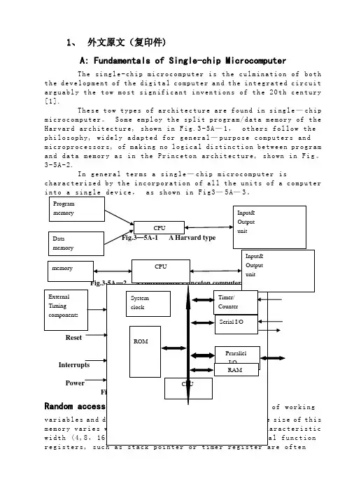
1、外文原文(复印件)A: Fundamentals of Single-chip MicrocomputerTh e si ng le-ch i p mi cr oc om pu ter is t he c ul mi nat i on o f bo th t h e d ev el op me nt o f th e d ig it al com p ut er an d t he int e gr at ed ci rc ui ta r gu ab ly th e t ow m os t s i gn if ic ant i nv en ti on s o f t h e 20t h c en tu ry[1].Th es e to w t ype s o f a rc hi te ct ur e a re fo un d i n s i ng le—ch ip m i cr oc om pu te r。
S o me em pl oy th e s p li t p ro gr am/d at a me mo ry of t he H a rv ar d ar ch it ect u re, sh ow n in Fi g.3-5A—1,ot he r s fo ll ow t hep h il os op hy, wi del y a da pt ed f or ge n er al—pu rp os e c o mp ut er s an dm i cr op ro ce ss or s, of ma ki ng no lo gi c al di st in ct io n be tw ee n p ro gr am a n d da ta m em or y a s i n th e Pr in cet o n ar ch it ec tu re,sh ow n in F ig。
3-5A-2.In g en er al te r ms a s in gl e—ch i p mi cr oc om pu ter isc h ar ac te ri zed b y the i nc or po ra tio n of al l t he uni t s o f a co mp ut er i n to a s in gl e de v i ce,as s ho wn i n F ig3—5A—3。
翻译原文

编号:毕业设计(论文)外文翻译(原文)学院:计算机科学与工程学院专业:计算机科学与技术专业学生姓名:覃龙学号:0700720222指导教师单位:计算机科学与工程学院姓名:黄廷磊职称:教授2011年5月30 日Block RAM SummaryThe block RAM in Virtex-5 FPGAs stores up to 36K bits of data and can be configured aseither two independent 18 Kb RAMs, or one 36 Kb RAM. Each 36 Kb block RAM can beconfigured as a 64K x 1 (when cascaded with an adjacent 36 Kb block RAM), 32K x 1,16K x 2, 8K x 4, 4K x 9, 2K x 18, or 1K x 36 memory. Each 18 Kb block RAM can beconfigured as a 16K x 1, 8K x2 , 4K x 4, 2K x 9, or 1K x 18 memory.Similar to the Virtex-4 FPGA block RAMs, Write and Read are synchronous operations; thetwo ports are symmetrical and totally independent, sharing only the stored data. Each portcan beconfigured in one of the available widths, independent of the other port. Inaddition, the read port width can be different from the write port width for eac h port. Thememory content can be initialized or cleared by the configuration bitstream. During awrite operation the memory can be set to have the data output either remain unchanged,reflect the new data being written or the previous data now being overwritten.Virtex-5 FPGA block RAM enhancements include:I ncreased memory storage capability per block. Each block RAM can store up to 36Kbits of data.S upport of two independent 18K blocks, or a single 36K block RAM.E ach 36K block RAM can be set to simple dual-port mode, doubling data width of theblock RAM to 72 bits. The 18K block RAM can also be set to simple dual-port mode,doubling data width to 36 bits.Simple dual-port mode is defined as having one readonlyport and one write-only port with independent clocks.T wo adjacent block RAMs can be combined to one deeper 64K x 1 memory withoutany external logic.O ne 64-bit Error Correction Coding block is provided per 36 Kb block RAM or 36 KbFIFO. Separate encode/decode functionality is available.S ynchronous Set/Reset of the outputs to an initial value is available for both the latchand register modes of the block RAM output.A n attribute to configure the block RAM as a synchronous FIFO to eliminate flaglatency uncertainty.T he Virtex-5 FIFO does not have FULL flag assertion latency.Virtex-5 FPGA block RAM features:18, 36, or 72-bit wide ports can have an individual write enable per byte. This featureis popular for interfacing to an on-chip microprocessor.E ach block RAM contains optional address sequencing and control circuitry to operate as a built-in multirate FIFO memory. In Virtex-5 architecture, the block RAM can be configured as an18Kb or 36Kb FIFO.A ll inputs are registered with the port clock and have a setup-to-clock timing specification.A ll outputs have a read function or a read-during-write function, depending on the state of the write enable (WE) pin. The outputs are available after the clock-to-out timing interval. The read-during-write outputs have one of three operating modes:WRITE_FIRST, READ_FIRST, and NO_CHANGE.A write o peration requires one clock edge.A read operation requires one clock edge.A ll output ports are latched. The state of the output port does not change until the port executes another read or write operation. The default block RAM output is latch mode.T he output data path has an optional internal pipeline register. Using the regist ermode is strongly recommended. This allows a higher clock rate, however, it adds a clock cycle latency of one. Virtex-5 FPGA block RAM usage rules:T he Synchronous Set/R eset (SSR) port cannot be used when the ECC decoder is enabled (EN_ECC_READ = TRUE).T he setup time of the block RAM address and write enable pins must not be violated. Violating the address setup time (even if write enable is Low) will corrupt the datacontents of the block RAM.T he block RAM register mode SSR requires REGCE = 1 to reset the output DO register value. The block RAM array data output latch does not get reset in this mode. The block RAM latch mode SSR requires the block RAM enable, EN = 1, to reset the output DO latch value.A lthough RAMB18SDP (x36 18k block RAM) and RAMB36SDP (x72 36k block RAM)are simple dual-port primitives, the true dual-port primitives (RAMB18 and RAMB36) can be used with one read-only port and one write-only port. For example: a RAMB18s READ_WIDTH_A = 18, WRITE_WIDTH_B = 9, with WEA = 0 and WEB = 1 is effectively a simple dual-port block RAM with a smaller port width having been derived from the true dual-port primitive. Similarly, a ROM function can be built out of either the true dual-port (RAMB18 or RAMB36) or the simple dual-portblock RAM primitives (RAMB18SDP or RAMB36SDP).D ifferent read and write port width choices are available when using specific block RAM primitives. The parity bits are only available for the x9, x18, and x36 port widths. The parity bits should not be used when the read width is x1, x2, or x4. If the read width is x1, x2 or x4, the effective write width is x1, x2, x4, x8, x16, or x32. Similarly, when a write width is x1, x2, or x4, the actual available read width is x1, x2, x4, x8, x16, or x32 even though the primitive attribute isset to 1, 2, 4, 9, 18, or 36respectively. Table 4-1 shows some possible scenarios.Table 4-1: Parity Use SceneriesNotes:1. Do not use parity bits DIP/DOP when one port widths is less than nine and another port width is nineBlock RAM IntroductionIn addition to distributed RAM memory and high-speed SelectIO™ memory interfaces, Virtex-5devices feature a large number of 36 Kb block RAMs. Each 36 Kb block RAM contains two independently controlled 18 Kb RAMs. Block RAMs are placed in columns, and the total number of block RAM memory depends on the size of the Virtex-5 device. The 36 Kb blocks are cascadable to enable a deeper and wider memory implementation, with a minimal timing penalty. Embedded dual- or single-port RAM modules, ROM modules, synchronous FIFOs, and data width converters are easily implemented using the Xilinx CORE Generator™ block memory modules. Multirate FIFOs can be generated using the CORE Generator FIFO Generator module. The synchronous or asynchronous (multirate) FIFO implementation does not require additional CLB resources for the FIFO control logicsince it uses dedicated hardware resources.Synchronous Dual-Port and Single-Port RAMsData FlowThe true dual-port 36 Kb block RAM dual-port memories consist of a 36 Kb storage area and two completely independent access ports, A and B. Similarly, each 18 Kb b lock RAM dual-port memory consists of an 18 Kb storage area and two completely independent access ports, A and B. The structure is fully symmetrical, and both ports are interchangeable. Figure 4-1 illustrates the true dual-port data flow. Table 4-2 lists the port names and descriptions. Data can be written to either or both ports and can be read from either or both ports. Each write operation is synchronous, each port has its own address, data in, data out, clock, clock enable, and write enable. The read and write operations are synchronousand require a clock edge. There is no dedicated monitor to arbitrate the effect of identical addresses onboth ports. It is up to the user to time the two clocks appropriately. Conflicting simultaneous writes to the same location never cause any physical damage but can result in data uncertainty.Read OperationIn latch mode, the read operation uses one clock edge. The read address is registered on the read port, and the stored data is loaded into the output latches after the RAM access time. When using the outputregister, the read operation will take one extra latency cycle.Write OperationA write operation is a single clock-edge operation. The write address is registered on the write port, andthe data input is stored in memory.Write ModesThree settings of the write mode determines the behavior of the data available on the output latches after a write clock edge: W RITE_FIRST, REA D_FIRST, and NO_CHANGE. Write mode selection is set by configuration. The Write mode attribute can be individually selected for each port. The default mode is WRITE_FIRST. W RITE_FIRST outputs thenewly written data onto the output bus. REA D_FIRST outputs the previously stored data while new data is being written. NO_CHANGE maintains the output previously generated by a read operation. For the simple dual port block RAM, the Write mode is always READ_FIRST in ECC configuration,and therefore no collision can occur when used in synchronous mode.WRITE_FIRST or Transparent Mode (Default)In WRITE_FIRST mode, the input data is simultaneously written into memory an d stored in the data output (transparent write), as shown in Figure 4-2. These waveforms correspond to latch modewhetREAD_FIRST or Read-Before-Write ModeIn REA D_FIRST mode, data previously stored at the write address appears on the output latches, while the input data is being stored in memory (read before write). The waveforms in Figure 4-3 correspond to latch mode when the optional output pipeline register is not usdedNO_CHANGE ModeIn NO_CHANGE mode, the output latches remain unchanged during a write operation. As shown in Figure 4-4, data output remains the last read data and is unaffected by a write operation on the same port. These waveforms correspond to latch mode when the optional output pipeline register is not used.Conflict AvoidanceVirtex-5 FPGA block RAM memory is a true dual-port RAM where both ports can access any memory location at any time. When accessing the same memory location from both ports, the user must, however, observe certain restrictions. There are two fundamentally different situations: The two ports either have a common clock (synchronous clocking), or the clock frequency and phase is different for the two ports (asynchronous clocking).Asynchronous ClockingAsynchronous clocking is the more general case, where the active edges of both clocks do not occur simultaneously:T here are no timing constraints when both ports perform a read operation.W hen one port performs a write operation, the other port must not read- or writeaccess the same memory location. The simulation model will produce an error if this condition is violated. If this restriction is ignored, a read or write operation willproduce unpredictable results. There is, however, no risk of physical damage to the device. If a read and write operation is performed, then the write will store valid data at the write location. Synchronous ClockingSynchronous clocking is the special case, where the active edges of both port clocks occur simultaneously:T here are no timing constraints when both ports perform a read operation.W hen one port performs a write operation, the other port must not write into the same location, unless both ports write identical data.W hen one port performs a write operation, the write operation succeeds; the other port can reliably read data from the same location if the write port is in READ_FIRST mode. DATA_OUT on bothports will then reflect the previously stored data. If the write port is in either WRITE_FIRST or inNO_CHA NGE mode, then the DATAOUT on the read port would become invalid (unreliable). Themode setting of the read-port does not affect this operation.Additional Block RAM Features in Virtex-5 Devices Optional Output RegistersThe optional output registers improve design performance by eliminating routing delay to the CLB flip-flops for pipelined operation. An independent clock and clock enable input is provided for these output registers. As a result the output data registers hold the value independent of the input register operation. Figure 4-5 shows the optional output register.Independent Read and Write Port Width SelectionEach block RAM port has control over data width and address depth (aspect ratio). The true dual-portblock RAM in Virtex-5 FPGAs extends this flexibility to Read and Write where each individual portcan be configured with different data bit widths. For example, port A can have a 36-bit Read width anda 9-bit Write width, and port B can have a 18-bit Read width and a 36-bit Write width. See “BlockRAM Attributes,” page 126. If the Read port width differs from the Write port width, and is configuredin WRITE_FIRST mode, then DO shows valid new data for all the enabled write bytes. The DO portoutputs the original data stored in memory for all not enabled bytes. Independent Read and Write portwidth selection increases the efficiency of implementing a content addressable memory (CAM) inblock RAM. Th is option is available for all Virtex-5 FPGA true dual-port RAM port sizes and modes. Simple Dual-Port Block RAMEach 18 Kb block and 36 Kb block can also be configured in a simple dual-port RAM mode. In this mode, the block RAM port width doubles to 36 bits for the 18 Kb block RAM and 72 bits for the 36 Kb block RAM. In simple dual-port mode, independent Read and Write operations can occur simultaneously, where port A is designated as the Read port and port B as the Write port. When the Read and Write port access the same data location at the same time, it is treated as a collision, similar to the port collision in true dual-port mode. Readback through the configuration port is not supported in simple dual-port block RAM mode. Figure 4-6 shows the simple dual-port data flowCascadable Block RAMIn the Virtex-5 block RAM architecture, two 32K x 1 RAMs can be combined to form one 64K x 1 RAM without using local interconnect or additional CLB logic resources. Any two adjacent block RAMs can be cascaded to generate a 64K x 1 block RAM. Increasing the depth of the block RAM by cascading two block RAMs is available only in the 64K x 1 mode. Further information on cascadable block RAM is described in the “Additional RAMB18 and RAMB36 Primitive Design Considerations” section. For other wider and/or deeper sizes, consult the Creating Larger RAM Structures section. Figure 4-7 shows the block RAM with the appropriate ports connected in the Cascadable mode.Byte-wide Write EnableThe byte-wide write enable feature of the block RAM gives the capability to write eight bit (one byte) portions of incoming data. There are four independent byte-wide write enable inputs to the RAMB36 true dual-port RAM. There are eight independent byte-wide write enable inputs to block RAM in simple dual-port mode (RAMB36SDP). Table 4-4 summarizes the byte-wide write enables for the 36K and 18K block RAM. Each byte-wide write enable is associated with one byte of input data and one parity bit. A ll byte-wide write enable inputs must be driven in all data width configurations. This feature is useful when using block RAM to interface with a microprocessor. Byte-wide write enable is not available in the multirate FIFO or ECC mode. Byte-wide write enable is further described in the “Additional RAMB18 and RAMB36 Primitive Design Considerations” section.Figure 4-8 shows the byte-wide write-enable timing diagram for the RAMB36.When the RAMB36 is configured for a 36-bit or 18-bit wide data path, any port can restrict writing to specified byte locations within the data word. If configured in READ_FIRST mode, the DO bus shows the previous content of the whole addressed word. In WRITE_FIRST mode, DO shows a combination of the newly written enabled byte(s), and the initial memory contents of the unwritten bytes.Block RAM Error Correction CodeBoth block RAM and FIFO implementations of the 36 Kb block RAM support a 64-bit Error Correction Code (ECC) implementation. The code is used to detect single and double-bit errors inblock RAM data read out. Single-bit errors are then corrected in the output data.Block RAM Library PrimitivesThe Virtex-5 FPGA block RAM library primitives, RAMB18 and RAMB36, are the basic building blocks for all block RAM configurations. Other block RAM primitives and macros are based on these primitives. Some block RAM attributes can only be configured usingone of these primitives (e.g., pipeline register, cascade, etc.). See the “Block RAM Attributes” section. The input and output data buses are represented by two buses for 9-bit width (8 + 1), 18-bit width (16 + 2), and 36-bit width (32 + 4) configurations. The ninth bit associated with each byte can store parity/error correction bits or serve as additional data bits. No specific function is performed on the ninth bit. The separate bus for parity bits facilitates some designs. However, other designs safely use a 9-bit, 18-bit, or 36-bit bus by merging the regular data bus with the parity bus. Read/write and storage operations are identical for all bits, including the parity bits.Block RAM Port SignalsEach block RAM port operates independently of the other while accessing the same set of 36K-bit memory cells.Clock - CLK[A|B]Each port is fully synchronous with independent clock pins. All port input pins have setup time referenced to the port CLK pin. The output data bus has a clock-to-out time referenced to the CLK pin. Clock polarity is configurable (rising edge by default).Enable - EN[A|B]The enable pin affects the read, write, and set/reset functionality of the port. Ports with an inactive enable pin keep the output pins in the previous state and do not write data to the memory cells. Enable polarity is configurable (active High by default).Byte-wide Write Enable - WE[A|B]To write the content of the data input bus into the addressed memory location, both EN and WE must be active within a set-up time before the active clock edge. The output latches are loaded or not loaded according to the write configuration (W RITE_FIRST, READ_FIRST, NO_CHA NGE). When inactive, a read operation occurs, and the contents of the memory cells referenced by the address bus appear on the data-out bus, regardless of the write mode attribute. Write enable polarity is not configurable (active High).Register Enable - REGCE[A|B]The register enable pin (REGCE) controls the optional output register. When the RAM is in register mode, REGCE = 1 registers the output into a register at a clock edge. The polarity of REGCE is not configurable (active High).Set/Reset - SSR[A|B]In latch mode, the SSR pin forces the data output latches, to contain the value SRVA L. See“Block RAM Attributes,” pag e 126. When the optional output registers are enabled, the data output registers can also be forced by the SSR pin to contain the value SRVA L. SSR does not affect the latched value. The data output latches or output registers are synchronously asserted to 0 or 1, including the parity bit. Each port has an independent SRVA L[A|B] attribute of 36 bits. This operation does not affect RAM memory cells and does not disturb write operations on the other port. Similar to the read and write operation, the set/reset function is active only when the enable pin of the port is active. Set/reset polarity is configurable (active High by default).Address Bus - ADDR[A|B]<13:#><14:#><15:#>The address bus selects the memory cells for read or write. The data bit width of the port determinesthe required address bus width for a single RAMB18 or RAMB36, as shown in Table 4-6 and Table 4-7.For cascadable block RAM using the RAMB36, the data width is one bit, and the address bus is 16 bits <15:0>. The address bit 15 is only used in cascadable block RAM. For noncascading block RAM, connect High. Data and address pin mapping is further described in the “Additional RAMB18 and RAMB36 Prim itive Design Considerations”section.Data-In Buses - DI[A|B]<#:0> & DIP[A|B]<#:0>Data-in buses provide the new data value to be written into RAM. The regular data-in bus (DI), plus the parity data-in bus (DIP) when available, have a total width equal to the port width. For example the 36-bit port data width is represented by DI<31:0> and DIP<3:0>, as shown in Table 4-6 and Table 4-7. Data-Out Buses - DO[A|B]<#:0> and DOP[A|B]<#:0>Data-out buses reflect the contents of memory cells referenced by the address bus at the last active clock edge during a read operation. During a write operation (WRITE_FIRST or READ_FIRST configuration), the data-out buses reflect either the data being written or the stored value before write. During a write operation in NO_CHANGE mode, data-out buses are not changed. The regular data-out bus (DO) plus the parity data-out bus (DOP) (when available) have a total width equal to the port width, as shown in Table 4-6 and Table 4-7.Cascade In - CASCADEINLAT[A|B] and CASCADEINREG[A|B]The CASCA DEIN pins are used to connect two block RAMs to form the 64K x 1 mode (Figure 4-10.) This pin is used when the block RAM is the UPPER block RAM, and is connected to the CASCADEOUT pins of the LOW ER block RAM of the same port. When cascade mode is not used, this pin does not need to be connected. Refer to the “Cascadable Block RAM” for further information.CascadeOut - CASCADEOUTLAT[A|B] and CASCADEOUTREG[A|B]The CASCA DEOUT pins are used to connect two block RAMs to form the 64K x 1 mode. This pin is used when the block RAM is the LOW ER block RAM, and is connected to the CASCADEIN pins of the UPPER block RAM of the same port. When cascade mode is not used, this pin does not need to be connected. Refer to the “Cascadable Block RAM” for further information.Inverting Control PinsFor each port, the six control pins (CLK, EN, and SSR) each have an individual inversion option. EN and SSR control signals can be configured as active High or Low, and the clock can be active on a rising or falling edge (active High on rising edge by default), without requiring other logic resources. GSRThe global set/reset (GSR) signal of a Virtex-5 device is an asynchronous global signal that is active at the end of device configuration. The GSR can also restore the initial Virtex-5 device state at any time. The GSR signal initializes the output latches to the INIT (simple dual port), or to the INIT_A and INIT_B value (true dual port.) See “Block RAM Attributes.” A GSR signal has no impact on internal memory contents. Because it is a global signal, the GSR has no input pin at the functional level (block RAM primitive).Unused InputsUnused data and/or address inputs should be connected HighBlock RAM Address MappingEach port accesses the same set of 18,432 or 36,864 memory cells using an addressing scheme dependent on whether it is a RAMB18 or RAMB36. The physical RAM locations addressed for a particular width are determined using the following formula (of interest only when the two ports use different aspect ratios):END = ((A DDR + 1) Width) -1START = A DDR WidthTable 4-8 shows low-order address mapping for each port width.Block RAM AttributesAll attribute code examples are discussed in the “Block RAM Initialization in VHDL or Verilog Code” section. Further information on using these attributes is available in the“Additional RAMB18 and RAMB36 Primitive Design Considerations” section.Content Initialization - INIT_xxINIT_xx attributes define the initial memory contents. By default, block RAM memory is initialized with all zeros during the device configuration sequence. The 64 initialization attributes from INIT_00 through INIT_3F for the RAMB18, and the 128 initialization attributes from INIT_00 through INIT_7F for the RAMB36 represent the regular memory contents. Each INIT_xx is a 64-digit hex-encoded bit vector. The memory contents can be partially initialized and are automatically completed with zeros. The following formula is used for determining the bit positions for each INIT_xx attribute. Given yy = conversion hex-encoded to decimal (xx), INIT_xx corresponds to the memorycells as follows:f rom [(yy + 1) 256] – 1t o (yy) 256For example, for the attribute INIT_1F, the conversion is as follows:y y = conversion hex-encoded to decimal (xx) “1F” = 31f rom [(31+1) 256] – 1 = 8191t o 31 256 = 7936More examples are given in Table 4-9.Content Initialization - INITP_xxINITP_xx attributes define the initial contents of the memory cells corresponding to DIP/DOP buses (parity bits). By default these memory cells are also initialized to all zeros. The initialization attributes represent the memory contents of the parity bits. The eight initialization attributes are INITP_00 through INITP_07 for the RAMB18. The 16 initialization attributes are INITP_00 through INITP_0F for the RAMB36. Each INITP_xx is a 64-digit hex-encoded bit vector with a regular INIT_xx attribute behavior. The same formula can be used to calculate the bit positions initialized by a particular INITP_xx attribute.Output Latches Initialization - INIT (INIT_A or INIT_B)The INIT (single-port) or INIT_A and INIT_B (dual-port) attributes define the output latches or output register values after configuration. The width of the INIT (INIT_A andINIT_B) attribute is the port width, as shown in Table 4-10. These attributes are hexencoded bit vectors, and the default value is 0. In cascade mode, both the upper and lower block RAM should be initialized to the same value. Output Latches/Registers Synchronous Set/Reset (SRVAL_[A|B])The SRVA L (single-port) or SRVA L_A and SRVA L_B (dual-port) attributes define output latch values when the SSR input is asserted. The width of the SRVA L (SRVA L_A and SRVA L_B) attribute is the port width, as shown in Table 4-10. These attributes are hexencoded bit vectors and the default value is 0. This attribute sets the value of the output register when the optional output register attribute is set. When the register is not used, the latch gets set to the SRVA L instead. In the 36-bit mode, SRVA L[35:32] corresponds toDP[3:0].Output Latches/Registers Synchronous Set/Reset (SRVAL_[A|B])The SRVA L (single-port) or SRVA L_A and SRVA L_B (dual-port) attributes define output latch values when the SSR input is asserted. The width of the SRVA L (SRVA L_A and SRVA L_B) attribute is the port width, as shown in Table 4-10. These attributes are hexencoded bit vectors and the default value is 0. This attribute sets the value of the output register when the optional output register attribute is set. When the register is not used, the latch gets set to the SRVA L instead. In the 36-bit mode, SRVA L[35:32] corresponds toDP[3:0].Optional Output Register On/Off Switch - DO[A|B]_REGThis attribute sets the number of pipeline register at A/B output of the block RAM. The valid values are 0 (default) or 1.Extended Mode Address Determinant - RAM_EXTENSION_[A|B]This attribute determines whether the block RAM of interest has its A/B port as UPPER/LOW ER address when using the cascade mode. Refer to the “Cascadable Block RAM”section. When the block RAM is not used in cascade mode, the default value isNONE.Read Width - READ_WIDTH_[A|B]This attribute determines the A/B read port width of the block RAM. The valid values are:0 (default), 1, 2, 4, 9, 18, and 36.Write Width - WRITE_WIDTH_[A|B]This attribute determines the A/B write port width of the block RAM. The valid values are:0 (default), 1, 2, 4, 9, 18, and 36.Write Mode - WRITE_MODE_[A|B]This attribute determines the write mode of the A/B input ports. The possible values are WRITE_FIRST (default), READ_FIRST, and NO_CHANGE. Additional information on the write modes is in the “Write Modes” sectionBlock RAM Location ConstraintsBlock RAM instances can have LOC properties attached to them to constrain placement. Block RAM placement locations differ from the convention used for naming CLB locations, allowing LOC properties to transfer easily from array to array. The LOC properties use the following form:。
外文翻译英语原文编号01
Vol.25 No.2 PANG Chaoming et al: Methods of Modifying the Brittle (156)DOI 10.1007/s11595-010-1156-yMethods of Modifying the Brittle Behavior ofCementitious CompositesPANG Chaoming1, SUN Wei1, LEUNG Christopher KY2(1.College of Materials Science and Engineering, Southeast University, Jiangsu Key laboratory of Construction Materials, Nanjing 211189,China;2. Department of Civil and Environmental Engineering, Hong Kong University of Science and Technology, Hong Kong, China SAR)Abstract: We put forward effective methods of increasing the tensile strain of cementitiouscomposites with 2% PVA fiber and high fly ash content. The test results show that curing condition hasa significantly effect on the tensile performance. It is approved that the specimens incorporated ap-propriate volume fraction rubber powder and lightweight aggregate greatly increase the tensile strain ofcomposites at medium-term age, but indefinitely at long-term age. To a certain extent, EVA can limitedlyenhance the tensile performance of comentitious composites owing to the formation of polymer membraneand the hindered hydration of cement.Key word: high-ductility cementitious composites (HDCC); tensile properties; high content offly ash; rubber powder; light aggregate; ethylene vinyl alcohol latex powder1 IntroductionCementitious composites are widely used as the majority of structural materials. However, cementitious composites are limited to some special projects due to the inherently brittle behavior. Most efforts have been made to modify the brittle behavior of cementitious composites all along. As a result, the fiber reinforced cementitious composites (FRCC) occurred. In comparison to plain concrete, FRC usually deteriorates the tensile or bending properties by the formation of several cracks and a main crack. In the past two decades, Li, Leung and Wu etc[1-3] investigated the bridging stress of fiber and proposed the theory for high-ductility cementitious composites (here-after abbreviated as HDCCs) or pseudo ductility cemen-titious composites or pseudo strain hardening cementi-tious composites, based on the two nondimensionalized parameters energy absorption rate and normalized flaw size. It has been demonstrated that the ductility behaviors of brittle materials can be achieved by multiple cracks in steady state along the length of the specimen and behave pseudo strain hardening (abbr. PSH). Hereafter, the theories for PSH in the cementitious composites were gradually developed by Li and his co-workers, and the particular theory for “composite design”, based on the micro mechanics parameter, by emphasizing the proper integrant materials and interface was proposed[4,5]. The cementitious composite with high tensile strain capacity of 3%-6%, whose strain capacity is far outperforming conventional cementitious composites, was achieved[6].Recently increasing researchers are interesting to the new type of fiber reinforced cementitious composite. However, it is not easy to achieve PSH in discontinuous random fiber reinforced. Strain due to a little deviation of raw materials occur even if the well-known same mixture proportion of ECC is used due to a little deviation of raw materials. Meanwhile, the design method of existing theory depend on known experimental micro mechanics parameters, such as the fracture toughness, fiber content, fiber strength, fiber distribution, the bridging stress and interface properties between fiber matrix, etc. Moreover, it is very difficult to achieve the accurate fiber distribu-tion and bridging stress due to the randomization and inhomogeneity of the distribution of fiber in composites. But the micromechanical parameters and the ductile be-havior is strongly affected by the bridging stress governed by fiber debonding, fiber bending, fiber rupture, matrix spalling and their coupling[2].The focus in the current study is to discover the ef-ficacious methods to increase the tensile strain of HDCC. It is well know that curing conditions have a significantly©Wuhan University of Technology and Springer-Verlag Berlin Heidelberg 2010 (Received: Jan. 6, 2009; Accepted: Oct. 16, 2009)PANG Chaoming(庞超明): Ph D candidate; E-mail: pangchao@seu. edu. cnJournal of Wuhan University of Technology-Mater. Sci. Ed. Feb.2010157conditions were used for comparison, considering that the structures in practice project are often exposed to different environment and different curing condition are usually applied according to the lab environment in the different researches. For the brittle cementitious com-posites, the matrix cracking strength, which is determined by the matrix toughness and the largest crack or flaw in the stress section of specimen provided that the matrix cracking is controlled by fracture process, does not de-crease unlimitedly but reaches a lower bound at steady state cracking stress with the growing flaw size [7]. Moreover, the discontinuous pre-existing flaw or mi-cro-voids may relax the crack-tip stress triaxiality, dif-fuse the intensity of crack-tip stress singularity and consume more energy. To ensure the formation of multiple cracks, it is desirable to introduce a rtificial flaws in the matrix to reduce its crack tip toughness and increase the crack size due to energy absorption of flaw [8]. Therefore, different materials, such as rubber powder and fine lightweight aggregate, were added to the composites to increase the strain capacity.2 ExperimentalSpecial green island brand P·II 52.5 cement was used. The range of particle size of fly ash is mainly 2-10 μm, and the active index of compressive strength at 7 days, 28 days and 90 days are the 86%, 84% and 96% respectively followed by ASTM C311-04. Polyvinyl alcohol fiber (abbr. PVAF) produced by Japan Kuraray Limited Corporation was used, and its density, length, diameter were 1.3 g/cm 3, 12 mm, 38 μm respectively,also its elastic modulus and rate of elongation is 33 GPaand 6.5% respectively.The particle size of silica fume, silica filler and silica sand used is 1-20 μm, 1-15 μm and 50-200 μm respec-tively. ADVA105 superplastics admixture (abbr. Sp) was %produced by Grace Co.LTD and its solid content is 23. SP4000 (abbr. SP4), which is ethylene vinyl alcohol (abbr. EVA) latex powder and is produced by Japan Kuraray Trading Co.LTD, was used in this study. The particle size of lightweight aggregate (abbr. LA) is between 1 mm and 3 mm, whose specific density is 1 500 kg/m 3, and the loose volume weight is about 780 kg/m 3. Rubber pow-der with the particle size of 0.4 mm was also used.The specimen was demoulded 24 hours after casting, where the temperature and relative humidity was about 20±2 ℃ and (60±5)% respectively, then cured in water at curing room , where the temperature is 27 ℃ (ac-cording to the BS standard). The nominal sizes used for tensile performance and compressive performance are about 350×50×15 mm and 40×40×40 mm respec-tively. The dimensions of the specimen were accurately measured by vernier caliper and all the specimens were polished to smooth surface before testing to obtain ac-curate experimental results, and at least three specimens were tested at each age.The tensile performance was tested under the dis-placement control in the MTS810-25 kN materials test-ing system with the displacement rate of 0.15 mm/min. Linear variable displacement transducer was used to measure the displacement at the gage length of 150 mm for the more accuracy purpose. The first crack strain εfc , the peak strain εp and the maximum strain εm repre-sent to the strain corresponding to the first crack stress σTc when the first crack occurred, peak stress σTp when the stress reaches the peak, and the strain when the stress descends up to 90% σTp , respectively.3 Results3.1 Effect of curing conditions on me-chanical properties of HDCCAccording to previous work, two mix proportions shown in Table 1 were used, i e , SP4 and W1 with high volume fraction fly ash and low ratio of water to binder (cement and fly ash). Table 1 Mix proportion in mass of HDCC No. cement FA SP4 sand water Sp PVAF SP4 1 3.9 0.1 1.0 1.1 0.022 0.090 W1 1 4.0 0 1.0 1.0 0.023 0.096For the purpose of comparing the effect of different curing condition on the tensile performance, four types of curing conditions were applied in mixture SP4 as fol-lowing: full dry curing in room temperature condition after demoulded, which corresponds to symbol D in the denominated title in Table 2, dry curing in room tem-perature condition after 3-day curing in water corre-sponding to symbol W3D, dry curing in room tempera-ture condition after 7-day water curing corresponding to symbol W7D, and 28-day water curing corresponding to symbol W. The only two types of curing conditions wereused in mixture W1: dry curing in room temperature condition after 7 days water curing and full water curing. Table 2 list the test results of the tensile strength and strain and compressive strength on different curing con-ditions at the age of 7-day and 28-day.Vol.25 No.2 PANG Chaoming et al : Methods of Modifying the Brittle …1583.2 Effect of rubber powder on mechanic-al properties of HDCCThe specimen without rubber powder is regarded as control specimen, and two mixtures of HDCCs with the rubber powder were prepared. SR7 and SR11 represent for HDCC of the volume fraction of 7% and 11%, re-spectively. For estimating the long-term performance, the accelerated curing method was conducted, that is, after cured in water for 7 days, at least three specimens were put to the heat curing room for 72 hours, where the temperature and relative humidity are 80 ℃%and 95respectively, the mechanical performance was measured after being cooled down in the room temperature condi-tion. The mix proportion used and test results are sum-marized in Table 3, Table 4 respectively. Heat curing corresponds to symbol HC. Fig.1 shows the tensile stress versus strain curves of SR7 and SR11 at 28 days.3.3 Effect of lightweight aggregate onmechanical properties of HDCC For the purpose of researching the effect of light-weight aggregate on the tensile strain of HDCC with highflyash content, the volume fraction of 3.5% was incor-porated into the mixture, and the mix proportion was listed in Table 5. The specimen FA3 and FA3LA corre-spond to control specimen and specimen with lightweight aggregate, respectively.The test results are shown in Table 6. The condition of heat curing is the same as mentioned above. Fig.2(a) and Fig.2(b) showed the typical stress vs strain curve of FA3 and FA3LA3.5 at different age: 7 days, 28 days and heat curing 3 days.Table 2 Test results of HDCC on different curing conditionsSP4D SP4W3D SP4W7D SP4W W1 7-day 28-day 7-day 28-day 28-day 90-day 7-day 28-day W7 W28 W7DσTfc /MPa 2.68 2.36 2.91 2.54 3.26 3.28 2.70 3.36 2.76 3.65 3.62 εfc /% 0.080 0.069 0.075 0.096 0.080 0.089 0.119 0.060 0.088 0.047 0.128 σTp /MPa 3.30 3.39 3.76 3.14 4.07 3.62 3.17 4.02 3.27 3.81 4.69εp /% 1.53 3.95 2.69 2.56 2.82 2.58 2.78 0.77 1.050.35 2.94 εm /% 1.69 4.28 2.80 2.79 3.54 2.66 2.97 1.81 1.360.54 3.39 σcom /MPa 22.8 27.2 — — — — 23.4 36.0 35.8 58.9 — Table 3 Mix proportion in mass of HDCC with different volume fraction of rubber powder No. Cement FA Filler Sand Rubber Water Sp PVAFControl 1 1.50 0.25 1.00 0 0.63 0.015 0.057 SR7 1 1.50 0.25 0.65 0.163 0.58 0.020 0.055 SR11 1 1.50 0.25 0.40 0.263 0.58 0.020 0.055 Table 4 Test results of HDCCs with different volume fraction of rubber powderControl SR7 SR117-day 28-day 90-day 7-day 28-day HC 7-day 28-day HCσTfc /MPa 3.58 4.61 3.81 2.31 2.60 3.63 2.19 2.31 3.28 εfc /% 0.050 0.042 0.027 0.036 0.022 0.039 0.034 0.051 0.041 σTp/MPa 4.30 5.05 4.53 2.49 3.00 3.81 2.72 3.18 3.57 εp /% 1.33 0.84 0.29 0.31 0.58 0.16 1.04 2.15 0.20 εm/% 1.59 0.98 0.39 0.54 1.07 0.71 1.40 2.49 0.34 σcom /MPa 49.6 66.2 — 29.7 35.7 40.5 24.8 31.4 37.0 Table 5 Mix proportion in mass No. Cement FA LA Sand Water Sp PVAF FA3 1 3 — 1 1 0.025 0.056 FA3LA 1 3 0.16 1 1 0.028 0.056 Table 6 Test results of HDCCs with or without lightweightaggregate FA3 FA3LA 7 d 28 d 90 d HC 7 d 28 d 90 d HCσTfc /MPa 1.42 2.68 3.60 4.38 2.86 3.15 3.25 6.42εfc /% 0.015 0.044 0.031 0.022 0.025 0.045 0.040 0.037 σTp /MPa 2.91 3.46 4.86 4.86 2.86 3.91 3.92 6.49εp /% 0.04 0.58 0.29 0.08 0.03 1.96 0.23 0.04 εm /% 1.16 0.96 0.66 0.31 1.40 2.07 0.54 0.38 σcom/MPa 21.5 44.7 69.5— 19.0 44.2 74.8 —Journal of Wuhan University of Technology-Mater. Sci. Ed. Feb.20101593.4 Effect of EVA powder on mechanicalproperties of HDCCA series of HDCCs specimens with or without EVA powder were also prepared, cured and tested at prescribed age followed by the test procedure. The condition of heat curing is also the same as mentioned above. The mix proportion used is listed in Table 7, and test results of tensile properties are presented in Table 8 and Fig.2(c) respectively. S is the control specimen, and SS4 is representative for HDCC with EVA powder.4 Discussion It can be concluded that the curing conditions have a great effect on the tensile properties from Table 1 and Table 2. The tensile properties exhibit a great difference at 28 days due to different curing condition for mixture SP4 and mixture W1. The HDCC cured in water per-forms better than that in room temperature condition atthe early age, however, as the age increases, the tensileperformance of HDCCs cured in room temperature condition shows an increasing tendency while that curedin the water decreases. The tensile strain of specimensthat of W3D is similar to that of W7D at 28 days, whichtest results also show the ultimate tensile strength has not direct relationship with the tensile strain, and high tensile strain do not mean low tensile strength, and vice versa . That can be explained as follows: curing condi-tion plays a significant influence on microstructure and macroscopical performance of cementitious composites. For fiber reinforced cementitious composites, there exists a distinctive layer of interface zone about 30-50 μm away from the fiber surface [9]. Also the interface will strongly influence the toughness of the compositesand frictional bond [10]. Generally the interface zone is considerable weaker than the matrix due to the large calcium hydroxide crystals and higher porosity for the FRCCs with steel fiber or polypropylene fiber [9], but thePVA fiber is a special organic fiber to the cementitiouscomposites. The majority of fibers used to the cementi-tious composites, such as steel fiber, polypropylenefiber,etc , will not react with the hydration products of cement, but the investigations by Akers show that [11], the PVA fiber performs surprisingly high chemical bonding between the PVA fiber and cement hydrationproducts due to the strong hydrophilic characteristic or hydrogen intermolecular bond induced by the hydroxyl groups, and as the age increase, while there are no evi-dent change in fiber properties, the bonding strengthbetween fiber and cement-based matrix will increase due to an increase in interface bond with age. The re-searches by Kanda T etc also shows that the apparent chemical bonding between PVA fiber and cement ma-,trix independent of the water-to cement ratio of matrix, is relatively stable and up to 30-40 MPa, but the value of friction bond, affected by water to cement ratio, is be-tween 2.2 MPa to 4.4 MPa when the water to cementvaries from 0.62 to 0.27[12]. Through the investigation by Li and his co-workers [3], only the FRCC with the appropriate fracture toughness of matrix and frictional Table 7 Mix proportion with or without EVA in mass No. Cement FA SF SP4 Sand Water Sp PVAF S 1 3.85 0.1 — 1 1.21 0.033 0.096 SS4 1 3.60 0.1 0.1 1 1.21 0.032 0.096 Table 8 Test results of HDCCs with or without EVAS SS47 d 28 d HC 7 d 28 d HCσTfc /MPa 1.15 3.32 4.37 1.86 3.14 3.89 εfc/% 0.021 0.067 0.029 0.057 0.086 0.049 σTp /MPa 1.94 3.43 4.90 2.03 3.42 4.75 εp /% 0.20 1.18 0.33 0.49 1.24 0.60εm /% 0.54 1.63 0.40 1.55 1.73 0.74 σcom /MPa 13.0 33.5 — 13.0 35.4 — (a) FA3 (b) FA3LA (c) S and SS4Fig.2 Stresses vs. Strain curves of FA3, FA3LA, S and SS4 at different ageVol.25 No.2 PANG Chaoming et al: Methods of Modifying the Brittle (160)and high strain capacity of FRCC can dominantly be achieved by using PVA fiber, and the interfacial fric-tional stress for FRCC with PSH behavior show the relative definite requirement and shall preferably be between 0.8 to 2.0 MPa[13], and the value can be achieved by applying oil agent[14]. In the present study, the PVA fiber, which had been coated with the oiling agent by Japan Kuraray Co. LTD, was employed. Ow-ing to low water to binder ratio and high content of fly ash (W/B=0.20, FA/C=4.0), and the specimens were kept only for 0-7 days in water and then longer than 20 days cured in room temperature condition, where there is no enough water for cement hydration, therefore they exhibit relative lower hydration degree and larger shrinkage than those cured in the water in all time. The lower hydration degree and larger shrinkage result in relatively lower frictional bond and weaker interface between PVA fiber and matrix[15]. Therefore, the former forms relatively looser structure and satisfies the re-quirement of low interfacial frictional stress, therefore performs better in strain hardening. Also the failure pat-tern of fiber rupture can be observed in testing process of the latter.In general, the definite range of interfacial fric-tional stress for achieving PSH behavior of FRCC, lower ratio of cement to binder, high fly ash content and PVA fiber properties contribute to the effect of curing condition on the tensile behavior.It can be deduced from Table 4, Table 6, Fig.1 and Fig.2 that the tensile strength of HDCC with rubber powder or light aggregate keep on growing, while the tensile strain also increases as the age increases from 7 days to 28 days, then decreased as the age continually grows up to 90 days or when heat curing was applied. That is because the fiber/matrix bond strength should saturate in a duration of less than 14-28 days, and ma-ture much earlier than matrix properties in cementi-tious[16]. But the high content of fly ash will considera-bly lower the chemical bond and delay the mature due to diluting the metal cation concentration on the fiber surface at early age and as a result the strain increases from 7 days to 28 days[17]. But the friction strength and the facture toughness of matrix continue to develop as age increase to 28 days as the second hydration of fly ash continually develop due to activity effect of fly ash under high temperature or at long age. When the imbal-ance of develop rate occurs, the strain decreases with the continual increasing age.From Table 4 and Table 6, not all the specimens show better tensile performance than the control specimen, only the tensile strain of the specimens with 11% volume fraction rubber powder or 3.5% light-weight aggregate increase comparing to the control specimen at 28 days. The specimens FA3 and FA3LA rapidly reach ultimate strength then crack, and only few cracks develop due to the high fracture toughness of matrix and the low friction between matrix and PVA fiber at 7 days, but the specimen can still maintain the considerable strain after cracking owing to fiber gradu-ally being pulled out. And the SR7 also shows the similar tendency at 28 days. It is possible that the frac-ture toughness of matrix develops faster than the chemical bond and the frictional bond due to the low ratio of water to binder and high content fly ash. However, the specimen with the 11% volume fraction rubber pow-der reaches 2.15% in comparison with only 0.84% for the corresponding control specimen and the ultimate strain of with or without lightweight aggregate varies from 1.96% to 0.58%. The similar test results, i e, pre-existing flaw or micro-voids can modify the brittle behavior of HDCC, were observed in the reference[8] as the pre-existing flaw can relax the crack-tip triaxiality, diffuse the intensity of crack-tip stress and consume more energy, and the lager flaw will not influence the cracking strength but reached a lower bound at a steady state of cracking stress.Table 8 and Fig.2 present that the EVA latex powder show a little positive effect on the tensile strain at different age. It is possible that the EVA as a polymer can form a layer polymer membrane, which hinders the hydration of cementitious materials, but the membrane only influences a little hydration process owing to the lower content, about 1% volume fraction, in compos-ites.In summary, the appropriate fracture toughness of matrix and frictional bond between fiber and matrix is necessary conditions to achieve the PSH behavior or high strain capability. The curing condition emphasize particularly on the influence of friction bond, but the incorporation of rubber powder and lightweight lay particular stress on the fracture toughness of matrix. However the incorporation of rubber powder and lightweight aggregate lower the fracture toughness of matrix and facilitate the crack of matrix, which will possibly lower the effect of curing condition on the tensile properties.Journal of Wuhan University of Technology-Mater. Sci. Ed. Feb.2010 1615 ConclusionsSome methods to modifying the brittle behavior of HDCC with high content fly ash are proposed. It is undoubted that curing condition will strongly influence the microstructure of cementitious composites. The test results show that curing condition has a significant ef-fect on the tensile strain of HDCC with high content fly ash, and dry curing condition will show the clear trend to increase the tensile strain of HDCC with high content fly ash. Not all the specimens but the specimens with appropriate volume fracture rubber powder and light-weight aggregate greatly enhance the tensile strain of HDCC at medium-term age, but indefinitely at long-term age impossibly because disconnected pre-existing flaw or micro-voids may relax the crack-tip, diffuse the intensity of crack-tip stress and significantly consume energy. To a certain extent, EVA can enhance the tensile performance of HDCC owing to the hindered hydration of cement based materials as a result of the formation of polymer membrane. But it is possible that the incorporation of rubber powder and lightweight will lower the effect of curing condition on the tensile per-formance.It also experimentally demonstrates that some specimens rapidly reach ultimate strength and crack, but some specimen can still maintain the considerable strain after cracking owing to fiber gradually being pulled out. The tensile stress keeps increasing, but the tensile strain firstly increases then decreases as the age continually grows because of the imbalance of develop rate between bond strength and matrix properties. References[1]LI V C and LEUNG C K Y. Steady-state and MultipleCracking of Short Random Fiber Composites[J]. Journal ofEngineering Mechanics, 1992, 118(11): 2 246-2 264[2]LEUNG C K Y and LI V C. Effect of Fiber Inclination onCrack Bridging Stress in Fiber Reinforced Brittle MatrixComposites[J]. Journal of Mechanical Physics, 1992, 40(6):1 333-1 362[3]LI V C and WU H C. Conditions for PseudoStrain-Hardening in Fiber Reinforced Brittle MatrixComposites[J]. Applied Mechanics Revolution, 1992, 45(8):390-398[4]LI V C, MISHRA D K and WU H C. Matrix Design forPseudo-Strain-Hardening Fiber Reinforced CementitiousComposites[J]. Materials and Structures, 1995, 28: 586-595 [5]KANDA T, LI V C and Member of ASCE. New Micro-mechanics Design Theory for Pseudostrain Hardness Ce-mentitious Composite[J]. Journal of Engineering Me-chanics, 1999, 125(4): 373-381[6]LI V C, WANG S and WU C. Tensile Strain- HardeningBehavior or Polyvinyl Alcohol Engineered CementitiousComposite (PVA-ECC)[J]. ACI Materials Journal, 2001,98(6): 483-492[7]MAESHALL D B, COX B N and EVANS A G. The Mechan-ics of Matrix Cracking in Brittle Matrix Fiber Composites[J].ACTA Metallurgical, 1985, 33(11): 2 013-2 021[8]WANG S and LI V C. Tailoring of Pre-Existing Flaw inECC Matrix for Saturated Strain Hardening[C]. Proceed-ings of the Fifth International Conference on FractureMechanics of Concrete and Concrete Structures. Colorado:Ia-FraMCos, 2004: 1 005-1 012[9]Li V C, WU H C, and CHAN Y W. Interfacial PropertyTailoring for Pseudo Strain-Hardening Cementitious Composites[C]. Advanced Technology on Design and Fabrication of Composite Materials and Structures. Neth-erlands: Kluwer Acad. Publ., 1995: 261-268[10]SUN W, MANDEL J A and SAID Samir. Studies of theProperties of the Fiber-Matrix Interface in Steel Fiber Re-inforced Mortar[J]. ACI Materials Journal, 1987, 84(12):101-109[11]AKERS S A S. Long Term Durability of PVA ReinforcingFibers in a Cement Matrix[J]. The International Journal ofCement Composite and Lightweight Concrete, 1989, 11:79-91[12]KANDA T and LI V C. Interface Property and ApparentStrength of High-Strength Hydrophilic Fiber in CementMatrix[J]. Journal of Materials in Civil Engineering, 1998,10(1): 5-13[13]LI V C and WANG S. Process for Increasing the Ductilityof High Performance Fiber-Reinforced Brittle Matrix Composites and Composites Produced Thereby[P]. US Patent 7169224. 2007-01-30[14]REDON C. Measuring and Modifying Interface Propertiesof PVA Fibers in ECC Matrix[J]. ASCE J. Materials inCivil Engineering, 2001, 13(6): 399-406[15]CHEN H SUN W and PIET S. Interfacial Transition ZoneBetween Aggregate and Paste in Cementitious Composites(II): Mechanism of Formation and Degradation of Interfa-cial Transition Zone Microstructure and Its Influence Factors[J].Journal of the Cement Ceramic Society, 2004, 32(1): 70-80 [16]CHAN Y W and LI V C. Age Effect on the Characteristicsof Fibre/Cement Interfacial Properties[J]. Journal of Ma-terials Science, 1997, 32: 5 287-5 292[17]WANG S and LI V C. Engineered Cementitious Compos-ites with High-Volume Fly Ash[J]. ACI Materials Journal,2007, 104(3): 233-241。
毕业论文外文翻译范例
外文原文(一)Savigny and his Anglo-American Disciple s*M. H. HoeflichFriedrich Carl von Savigny, nobleman, law reformer, champion of the revived German professoriate, and founder of the Historical School of jurisprudence, not only helped to revolutionize the study of law and legal institutions in Germany and in other civil law countries, but also exercised a profound influence on many of the most creative jurists and legal scholars in England and the United States. Nevertheless, tracing the influence of an individual is always a difficult task. It is especially difficult as regards Savigny and the approach to law and legal sources propounded by the Historical School. This difficulty arises, in part, because Savigny was not alone in adopting this approach. Hugo, for instance, espoused quite similar ideas in Germany; George Long echoed many of these concepts in England during the 1850s, and, of course, Sir Henry Sumner Maine also espoused many of these same concepts central to historical jurisprudence in England in the 1860s and 1870s. Thus, when one looks at the doctrinal writings of British and American jurists and legal scholars in the period before 1875, it is often impossible to say with any certainty that a particular idea which sounds very much the sort of thing that might, indeed, have been derived from Savigny's works, was, in fact, so derived. It is possible, nevertheless, to trace much of the influence of Savigny and his legal writings in the United States and in Great Britain during this period with some certainty because so great was his fame and so great was the respect accorded to his published work that explicit references to him and to his work abound in the doctrinal writing of this period, as well as in actual law cases in the courts. Thus, Max Gutzwiller, in his classic study Der einfluss Savignys auf die Entwicklung des International privatrechts, was able to show how Savigny's ideas on conflict of laws influenced such English and American scholars as Story, Phillimore, Burge, and Dicey. Similarly, Andreas Schwarz, in his "Einflusse Deutscher Zivilistik im Auslande," briefly sketched Savigny's influence upon John Austin, Frederick Pollock, and James Bryce. In this article I wish to examine Savigny's influence over a broader spectrum and to draw a picture of his general fame and reputation both in Britain and in the United States as the leading Romanist, legal historian, and German legal academic of his day. The picture of this Anglo-American respect accorded to Savigny and the historical school of jurisprudence which emerges from these sources is fascinating. It sheds light not only upon Savigny’s trans-channel, trans-Atlantic fame, but also upon the extraordinarily*M.H.Hoeflich, Savigny and his Anglo-American Disciples, American Journal of Comparative Law, vol.37, No.1, 1989.cosmopolitan outlook of many of the leading American and English jurists of the time. Of course, when one sets out to trace the influence of a particular individual and his work, it is necessary to demonstrate, if possible, precisely how knowledge of the man and his work was transmitted. In the case of Savigny and his work on Roman law and ideas of historical jurisprudence, there were three principal modes of transmission. First, there was the direct influence he exercised through his contacts with American lawyers and scholars. Second, there was the influence he exercised through his books. Third, there was the influence he exerted indirectly through intermediate scholars and their works. Let us examine each mode separately.I.INFLUENCE OF THE TRANSLATED WORKSWhile American and British interest in German legal scholarship was high in the antebellum period, the number of American and English jurists who could read German fluently was relatively low. Even those who borrowed from the Germans, for instance, Joseph Story, most often had to depend upon translations. It is thus quite important that Savigny’s works were amongst the most frequently translated into English, both in the United States and in Great Britain. His most influential early work, the Vom Beruf unserer Zeitfur Rechtsgeschichte und Gestzgebung, was translated into English by Abraham Hayward and published in London in 1831. Two years earlier the first volume of his History of Roman Law in the Middle Ages was translated by Cathcart and published in Edinburgh. In 1830, as well, a French translation was published at Paris. Sir Erskine Perry's translation of Savigny's Treatise on Possession was published in London in 1848. This was followed by Archibald Brown's epitome of the treatise on possession in 1872 and Rattigan's translation of the second volume of the System as Jural Relations or the Law of Persons in 1884. Guthrie published a translation of the seventh volume of the System as Private International Law at Edinburgh in 1869. Indeed, two English translations were even published in the far flung corners of the British Raj. A translation of the first volume of the System was published by William Holloway at Madras in 1867 and the volume on possession was translated by Kelleher and published at Calcutta in 1888. Thus, the determined English-speaking scholar had ample access to Savigny's works throughout the nineteenth century.Equally important for the dissemination of Savigny's ideas were those books and articles published in English that explained and analyzed his works. A number of these must have played an important role in this process. One of the earliest of these is John Reddie's Historical Notices of the Roman law and of the Progress of its Study in Germany, published at Edinburgh in 1826. Reddie was a noted Scots jurist and held the Gottingen J.U.D. The book, significantly, is dedicated to Gustav Hugo. It is of that genre known as an external history of Roman law-not so much a history of substantive Roman legal doctrine but rather a historyof Roman legal institutions and of the study of Roman law from antiquity through the nineteenth century. It is very much a polemic for the study of Roman law and for the Historical School. It imparts to the reader the excitement of Savigny and his followers about the study of law historically and it is clear that no reader of the work could possibly be left unmoved. It is, in short, the first work of public relations in English on behalf of Savigny and his ideas.Having mentioned Reddie's promotion of Savigny and the Historical School, it is important to understand the level of excitement with which things Roman and especially Roman law were greeted during this period. Many of the finest American jurists were attracted-to use Peter Stein's term-to Roman and Civil law, but attracted in a way that, at times, seems to have been more enthusiastic than intellectual. Similarly, Roman and Civil law excited much interest in Great Britain, as illustrated by the distinctly Roman influence to be found in the work of John Austin. The attraction of Roman and Civil law can be illustrated and best understood, perhaps, in the context of the publicity and excitement in the English-speaking world surrounding the discovery of the only complete manuscript of the classical Roman jurist Gaius' Institutes in Italy in 1816 by the ancient historian and German consul at Rome, B.G. Niebuhr. Niebuhr, the greatest ancient historian of his time, turned to Savigny for help with the Gaius manuscript (indeed, it was Savigny who recognized the manuscript for what it was) and, almost immediately, the books and journals-not just law journals by any means-were filled with accounts of the discovery, its importance to legal historical studies, and, of course, what it said. For instance, the second volume of the American Jurist contains a long article on the civil law by the scholarly Boston lawyer and classicist, John Pickering. The first quarter of the article is a gushing account of the discovery and first publication of the Gaius manuscript and a paean to Niebuhr and Savigny for their role in this. Similarly, in an article published in the London Law Magazine in 1829 on the civil law, the author contemptuously refers to a certain professor who continued to tell his students that the text of Gaius' Institutes was lost for all time. What could better show his ignorance of all things legal and literary than to be unaware of Niebuhr's great discovery?Another example of this reaction to the discovery of the Gaius palimpsest is to be found in David Irving's Introduction to the Study of the Civil Law. This volume is also more a history of Roman legal scholarship and sources than a study of substantive Roman law. Its pages are filled with references to Savigny's Geschichte and its approach clearly reflects the influence of the Historical School. Indeed, Irving speaks of Savigny's work as "one of the most remarkable productions of the age." He must have been truly impressed with German scholarship and must also have been able to convince the Faculty of Advocates, forwhom he was librarian, of the worth of German scholarship, for in 1820 the Faculty sent him to Gottingen so that he might study their law libraries. Irving devotes several pages of his elementary textbook on Roman law to the praise of the "remarkable" discovery of the Gaius palimpsest. He traces the discovery of the text by Niebuhr and Savigny in language that would have befitted an adventure tale. He elaborates on the various labors required to produce a new edition of the text and was particularly impressed by the use of a then new chemical process to make the under text of the palimpsest visible. He speaks of the reception of the new text as being greeted with "ardor and exultation" strong words for those who spend their lives amidst the "musty tomes" of the Roman law.This excitement over the Verona Gaius is really rather strange. Much of the substance of the Gaius text was already known to legal historians and civil lawyers from its incorporation into Justinian's Institutes and so, from a substantive legal perspective, the find was not crucial. The Gaius did provide new information on Roman procedural rules and it did also provide additional information for those scholars attempting to reconstruct pre-Justinianic Roman law. Nevertheless, these contributions alone seem hardly able to justify the excitement the discovery caused. Instead, I think that the Verona Gaius discovery simply hit a chord in the literary and legal community much the same as did the discovery of the Rosetta Stone or of Schliemann’s Troy. Here was a monument of a great civilization brought newly to light and able to be read for the first time in millenia. And just as the Rosetta Stone helped to establish the modern discipline of Egyptology and Schliemann's discoveries assured the development of classical archaeology as a modern academic discipline, the discovery of the Verona Gaius added to the attraction Roman law held for scholars and for lawyers, even amongst those who were not Romanists by profession. Ancillary to this, the discovery and publication of the Gaius manuscript also added to the fame of the two principals involved in the discovery, Niebuhr and Savigny. What this meant in the English-speaking world is that even those who could not or did not wish to read Savigny's technical works knew of him as one of the discoverers of the Gaius text. This fame itself may well have helped in spreading Savigny's legal and philosophical ideas, for, I would suggest, the Gaius "connection" may well have disposed people to read other of Savigny's writings, unconnected to the Gaius, because they were already familiar with his name.Another example of an English-speaking promoter of Savigny is Luther Stearns Cushing, a noted Boston lawyer who lectured on Roman law at the Harvard Law School in 1848-49 and again in 1851- 1852.Cushing published his lectures at Boston in 1854 under the title An Introduction to the Study of Roman Law. He devoted a full chapter to a description of the historical school and to the controversy betweenSavigny and Thibaut over codification. While Cushing attempted to portray fairly the arguments of both sides, he left no doubt as to his preference for Savigny's approach:The labors of the historical school have established an entirely new and distinct era in the study of the Roman jurisprudence; and though these writers cannot be said to have thrown their predecessors into the shade, it seems to be generally admitted, that almost every branch of the Roman law has received some important modification at their hands, and that a knowledge of their writings, to some extent, at least, is essentially necessary to its acquisition.译文(一)萨维尼和他的英美信徒们*M·H·豪弗里奇弗雷德里奇·卡尔·冯·萨维尼出身贵族,是一位出色的法律改革家,也是一位倡导重建德国教授协会的拥护者,还是历史法学派的创建人之一。
毕业论文文献外文翻译----危机管理:预防,诊断和干预文献翻译-中英文文献对照翻译
第1页 共19页中文3572字毕业论文(设计)外文翻译标题:危机管理-预防,诊断和干预一、外文原文标题:标题:Crisis management: prevention, diagnosis and Crisis management: prevention, diagnosis andintervention 原文:原文:The Thepremise of this paper is that crises can be managed much more effectively if the company prepares for them. Therefore, the paper shall review some recent crises, theway they were dealt with, and what can be learned from them. Later, we shall deal with the anatomy of a crisis by looking at some symptoms, and lastly discuss the stages of a crisis andrecommend methods for prevention and intervention. Crisis acknowledgmentAlthough many business leaders will acknowledge thatcrises are a given for virtually every business firm, many of these firms do not take productive steps to address crisis situations. As one survey of Chief Executive officers of Fortune 500 companies discovered, 85 percent said that a crisisin business is inevitable, but only 50 percent of these had taken any productive action in preparing a crisis plan(Augustine, 1995). Companies generally go to great lengths to plan their financial growth and success. But when it comes to crisis management, they often fail to think and prepare for those eventualities that may lead to a company’s total failure.Safety violations, plants in need of repairs, union contracts, management succession, and choosing a brand name, etc. can become crises for which many companies fail to be prepared untilit is too late.The tendency, in general, is to look at the company as a perpetual entity that requires plans for growth. Ignoring the probabilities of disaster is not going to eliminate or delay their occurrences. Strategic planning without inclusion ofcrisis management is like sustaining life without guaranteeinglife. One reason so many companies fail to take steps to proactively plan for crisis events, is that they fail to acknowledge the possibility of a disaster occurring. Like an ostrich with its head in the sand, they simply choose to ignorethe situation, with the hope that by not talking about it, it will not come to pass. Hal Walker, a management consultant, points out “that decisions will be more rational and better received, and the crisis will be of shorter duration, forcompanies who prepare a proactive crisis plan” (Maynard, 1993) .It is said that “there are two kinds of crises: those that thatyou manage, and those that manage you” (Augustine, 1995). Proactive planning helps managers to control and resolve a crisis. Ignoring the possibility of a crisis, on the other hand,could lead to the crisis taking a life of its own. In 1979, theThree-Mile Island nuclear power plant experienced a crisis whenwarning signals indicated nuclear reactors were at risk of a meltdown. The system was equipped with a hundred or more different alarms and they all went off. But for those who shouldhave taken the necessary steps to resolve the situation, therewere no planned instructions as to what should be done first. Hence, the crisis was not acknowledged in the beginning and itbecame a chronic event.In June 1997, Nike faced a crisis for which they had no existi existing frame of reference. A new design on the company’s ng frame of reference. A new design on the company’s Summer Hoop line of basketball shoes - with the word air writtenin flaming letters - had sparked a protest by Muslims, who complained the logo resembled the Arabic word for Allah, or God.The council of American-Islamic Relations threatened aa globalNike boycott. Nike apologized, recalled 38,000 pairs of shoes,and discontinued the line (Brindley, 1997). To create the brand,Nike had spent a considerable amount of time and money, but hadnever put together a general framework or policy to deal with such controversies. To their dismay, and financial loss, Nike officials had no choice but to react to the crisis. This incident has definitely signaled to the company that spending a little more time would have prevented the crisis. Nonetheless,it has taught the company a lesson in strategic crisis management planning.In a business organization, symptoms or signals can alert the strategic planners or executives of an eminent crisis. Slipping market share, losing strategic synergy anddiminishing productivity per man hour, as well as trends, issues and developments in the socio-economic, political and competitive environments, can signal crises, the effects of which can be very detrimental. After all, business failures and bankruptcies are not intended. They do not usually happen overnight. They occur more because of the lack of attention to symptoms than any other factor.Stages of a crisisMost crises do not occur suddenly. The signals can usuallybe picked up and the symptoms checked as they emerge. A company determined to address these issues realizes that the real challenge is not just to recognize crises, but to recognize themin a timely fashion (Darling et al., 1996). A crisis can consistof four different and distinct stages (Fink, 1986). The phasesare: prodromal crisis stage, acute crisis stage, chronic crisisstage and crisis resolution stage.Modern organizations are often called “organic” due tothe fact that they are not immune from the elements of their surrounding environments. Very much like a living organism, organizations can be affected by environmental factors both positively and negatively. But today’s successfulorganizations are characterized by the ability to adapt by recognizing important environmental factors, analyzing them, evaluating the impacts and reacting to them. The art of strategic planning (as it relates to crisis management)involves all of the above activities. The right strategy, in general, provides for preventive measures, and treatment or resolution efforts both proactively and reactively. It wouldbe quite appropriate to examine the first three stages of acrisis before taking up the treatment, resolution or intervention stage.Prodromal crisis stageIn the field of medicine, a prodrome is a symptom of the onset of a disease. It gives a warning signal. In business organizations, the warning lights are always blinking. No matter how successful the organization, a number of issues andtrends may concern the business if proper and timely attentionis paid to them. For example, in 1995, Baring Bank, a UK financial institution which had been in existence since 1763,ample opportunitysuddenly and unexpectedly failed. There wasfor the bank to catch the signals that something bad was on thehorizon, but the company’s efforts to detect that were thwarted by an internal structure that allowed a single employee both to conduct and to oversee his own investment trades, and the breakdown of management oversight and internalcontrol systems (Mitroff et al., 1996). Likewise, looking in retrospect, McDonald’s fast food chain was given the prodromalsymptoms before the elderly lady sued them for the spilling ofa very hot cup of coffee on her lap - an event that resulted in a substantial financial loss and tarnished image of thecompany. Numerous consumers had complained about thetemperature of the coffee. The warning light was on, but the company did not pay attention. It would have been much simplerto pick up the signal, or to check the symptom, than facing the consequences.In another case, Jack in the Box, a fast food chain, had several customers suffer intestinal distress after eating at their restaurants. The prodromal symptom was there, but the company took evasive action. Their initial approach was to lookaround for someone to blame. The lack of attention, the evasiveness and the carelessness angered all the constituent groups, including their customers. The unfortunate deaths thatptoms,occurred as a result of the company’s ignoring thesymand the financial losses that followed, caused the company to realize that it would have been easier to manage the crisis directly in the prodromal stage rather than trying to shift theblame.Acute crisis stageA prodromal stage may be oblique and hard to detect. The examples given above, are obvious prodromal, but no action wasWebster’s New Collegiate Dictionary, an acute stage occursacutewhen a symptom “demands urgent attention.” Whether the acutesymptom emerges suddenly or is a transformation of a prodromalstage, an immediate action is required. Diverting funds and other resources to this emerging situation may cause disequilibrium and disturbance in the whole system. It is onlythose organizations that have already prepared a framework forthese crises that can sustain their normal operations. For example, the US public roads and bridges have for a long time reflected a prodromal stage of crisis awareness by showing cracks and occasionally a collapse. It is perhaps in light of the obsessive decision to balance the Federal budget that reacting to the problem has been delayed and ignored. This situation has entered an acute stage and at the time of this writing, it was reported that a bridge in Maryland had just collapsed.The reason why prodromes are so important to catch is thatit is much easier to manage a crisis in this stage. In the caseof most crises, it is much easier and more reliable to take careof the problem before it becomes acute, before it erupts and causes possible complications (Darling et al., 1996). In andamage. However, the losses are incurred. Intel, the largest producer of computer chips in the USA, had to pay an expensiveprice for initially refusing to recall computer chips that proved unreliable o n on certain calculations. The f irmfirm attempted to play the issue down and later learned its lesson. At an acutestage, when accusations were made that the Pentium Chips were not as fast as they claimed, Intel quickly admitted the problem,apologized for it, and set about fixing it (Mitroff et al., 1996). Chronic crisis stageDuring this stage, the symptoms are quite evident and always present. I t isIt is a period of “make or break.” Being the third stage, chronic problems may prompt the company’s management to once and for all do something about the situation. It may be the beginning of recovery for some firms, and a deathknell for others. For example, the Chrysler Corporation was only marginallysuccessful throughout the 1970s. It was not, however, until the company was nearly bankrupt that amanagement shake-out occurred. The drawback at the chronic stage is that, like in a human patient, the company may get used to “quick fixes” and “band “band--aid”approaches. After all, the ailment, the problem and the crisis have become an integral partoverwhelmed by prodromal and acute problems that no time or attention is paid to the chronic problems, or the managers perceive the situation to be tolerable, thus putting the crisison a back burner.Crisis resolutionCrises could be detected at various stages of their development. Since the existing symptoms may be related todifferent problems or crises, there is a great possibility thatthey may be misinterpreted. Therefore, the people in charge maybelieve they have resolved the problem. However, in practicethe symptom is often neglected. In such situations, the symptomwill offer another chance for resolution when it becomes acute,thereby demanding urgent care. Studies indicate that today anincreasing number of companies are issue-oriented and searchfor symptoms. Nevertheless, the lack of experience in resolvinga situation and/or inappropriate handling of a crisis can leadto a chronic stage. Of course, there is this last opportunityto resolve the crisis at the chronic stage. No attempt to resolve the crisis, or improper resolution, can lead to grim consequences that will ultimately plague the organization or even destroy it.It must be noted that an unsolved crisis may not destroy the company. But, its weakening effects can ripple through the organization and create a host of other complications.Preventive effortsThe heart of the resolution of a crisis is in the preventiveefforts the company has initiated. This step, similar to a humanbody, is actually the least expensive, but quite often the mostoverlooked. Preventive measures deal with sensing potential problems (Gonzales-Herrero and Pratt, 1995). Major internalfunctions of a company such as finance, production, procurement, operations, marketing and human resources are sensitive to thesocio-economic, political-legal, competitive, technological, demographic, global and ethical factors of the external environment. What is imminently more sensible and much more manageable, is to identify the processes necessary forassessing and dealing with future crises as they arise (Jacksonand Schantz, 1993). At the core of this process are appropriate information systems, planning procedures, anddecision-making techniques. A soundly-based information system will scan the environment, gather appropriate data, interpret this data into opportunities and challenges, and provide a concretefoundation for strategies that could function as much to avoid crises as to intervene and resolve them.Preventive efforts, as stated before, require preparations before any crisis symptoms set in. Generally strategic forecasting, contingency planning, issues analysis, and scenario analysis help to provide a framework that could be used in avoiding and encountering crises.出处:出处:Toby TobyJ. Kash and John R. Darling . Crisis management: prevention, diagnosis 179-186二、翻译文章标题:危机管理:预防,诊断和干预译文:本文的前提是,如果该公司做好准备得话,危机可以更有效地进行管理。
5、外文文献翻译(附原文)产业集群,区域品牌,Industrial cluster ,Regional brand
外文文献翻译(附原文)外文译文一:产业集群的竞争优势——以中国大连软件工业园为例Weilin Zhao,Chihiro Watanabe,Charla-Griffy-Brown[J]. Marketing Science,2009(2):123-125.摘要:本文本着为促进工业的发展的初衷探讨了中国软件公园的竞争优势。
产业集群深植于当地的制度系统,因此拥有特殊的竞争优势。
根据波特的“钻石”模型、SWOT模型的测试结果对中国大连软件园的案例进行了定性的分析。
产业集群是包括一系列在指定地理上集聚的公司,它扎根于当地政府、行业和学术的当地制度系统,以此获得大量的资源,从而获得产业经济发展的竞争优势。
为了成功驾驭中国经济范式从批量生产到开发新产品的转换,持续加强产业集群的竞争优势,促进工业和区域的经济发展是非常有必要的。
关键词:竞争优势;产业集群;当地制度系统;大连软件工业园;中国;科技园区;创新;区域发展产业集群产业集群是波特[1]也推而广之的一个经济发展的前沿概念。
作为一个在全球经济战略公认的专家,他指出了产业集群在促进区域经济发展中的作用。
他写道:集群的概念,“或出现在特定的地理位置与产业相关联的公司、供应商和机构,已成为了公司和政府思考和评估当地竞争优势和制定公共决策的一种新的要素。
但是,他至今也没有对产业集群做出准确的定义。
最近根据德瑞克、泰克拉[2]和李维[3]检查的关于产业集群和识别为“地理浓度的行业优势的文献取得了进展”。
“地理集中”定义了产业集群的一个关键而鲜明的基本性质。
产业由地区上特定的众多公司集聚而成,他们通常有共同市场、,有着共同的供应商,交易对象,教育机构和其它像知识及信息一样无形的东西,同样地,他们也面临相似的机会和威胁。
在全球产业集群有许多种发展模式。
比如美国加州的硅谷和马萨诸塞州的128鲁特都是知名的产业集群。
前者以微电子、生物技术、和风险资本市场而闻名,而后者则是以软件、计算机和通讯硬件享誉天下[4]。
外文翻译原文.
e c o l o g i c a l e n g i n e e r i n g 28(2006124–130a v a i l ab l e a t w w w.sc i e n c ed i re c t.c omj o u r n a l h o m e p a g e :w w w.e l s e v i e r.c o m /l o c a t e /e c o l e n gPlant-biofilm oxidation ditch for in situ treatm ent of polluted watersQi-Tang Wu a ,∗,Ting Gao a ,Shucai Zeng a ,Hong Chua ba College of Natural Resources and Environment,South China Agricultural University,Guangzhou 510642,ChinabDepartment of Civil and Structural Engineering,Hong Kong Polytechnic University,Hung Hom,Kowloon,Hong Kong SAR,Chinaa r t i c l ei n f o Article history:Received 17December 2005Received in revised form 16May 2006Accepted 18May 2006Keywords:Plant-biofilm oxidation ditch (PBFODIn situWastewater treatmenta b s t r a c tEutrophication of surface water bodies is a problem of increasing environmental and ecolog-ical concern worldwide and is particularly serious in China.In the present study,oxidation ditches were connected to a lake receiving municipal sewage sludges.T wo 24m 2(width 2m,length 12mparallel plastic oxidation ditches material were installed on a lake near the inlet of the municipal sewage.Zizania caduciflora and Canna generalis were grown in the ditches with plastic floating supporters for the removal of N and P from the sewage.The experiment was conducted firstly with municipal sewage in autumn–winter seasons for about 150daysunder the following conditions:2m 3/h influent flow,0.75kW jet-flow aerator(air/water of 5,18h HRT (hydrological retention timeand a return ratio of 10.Then it was run with the polluted lake water in summer–autumn for about 160days with an aerator of 1.25kW and an influent of 6m 3/h (air/water 3.3,HRT 6h.The performance was quite stable during the experimental period for the municipal sewage treatment.The average removal rates of COD (chemical oxygen demand,SS (suspended solids,TP (total phosphorus,NH 4+-N and inorganic-N were 70.6,75.8,72.6,52.1and50.3%,respectively.For the polluted lake water treatment,the average concentrations of COD,NH 4+-N and TP were 42.7,13.1and 1.09mg/L,respectively,in the influent and were 25.1,6.4and 0.38mg/L,respectively,in the effluent.The capacity of the plants to remove N and P by direct uptake was limited,but the indi-rect mechanisms also occurred.The proposed process,transforming the natural lake into a wastewater treatment plant,could evidently reduce the costs of the sewage collection,the land space requirement and the construction compared with conventional sewage treat-ment plants,and is especially suited to conditions in south China and south-east Asia.©2006Elsevier B.V .All rights reserved.1.IntroductionMany water bodies are subject to eutrophication due to eco-nomic constraints in reducing point sources of nutrients and/or to a high proportion of diffuse sources,and the prob-lem is particularly common in China because the proportion of treated municipal sewage is still low due to the relatively high capital investmentrequired.Accordingly,43.5%of 130investi-gated major lakes in China were found to be highly eutrophied∗Corresponding author .Tel.:+862085280296;fax:+862085288326.E-mail address:qitangwu@ (Q.-T.Wu.and 45%were of intermediate status (Li et al.,2000.These pol-luted lakes were mainly located in economically developed regions and especially around cities where large amounts of municipal sewage are discharged without appropriate treat-ment.Increasingly,natural or constructed wetlands,including buffer zones(Correll,2005,are being used for removal of pol-lutants from wastewater or for treatment of stormwater runoff from agricultural land and other non-point sources (Mitsch ete c o l o g i c a l e n g i n e e r i n g28(2006124–130125Table1–COD and BOD5of the study lake sampled at three points for5days inMay2003COD(mg/LBOD5(mg/LBOD5/COD13May89.5135.700.4083.3334.500.4189.5136.600.4114May55.5624.800.4589.5135.200.3949.3820.900.4227May105.1141.300.3981.0832.300.40111.1141.000.3728May60.0026.830.4563.3327.700.4463.3327.000.4329May90.0035.700.4093.3337.000.40117.9949.400.42al.,2000;Coveney et al.,2002;Belmont et al.,2004.However, this method requires a large land area in addition to the lake in question.For in situ treatment of hypereutrophic water bodies where the transparency of the water does not allow regrowth of submerged macrophytes,phosphorus precipitation in eutrophic lakes by iron application(Deppe and Benndorf, 2002or by additions of lime(Walpersdorf et al.,2004has been reported.Aeration of river water has been employed to remediate polluted rivers since the1970s(Wang et al.,1999. Increasing oxygen transfer inflow by stones placed in rivers was studied by Cokgor and Kucukali(2004.Growingfloating aquatic macrophytes(Sooknah and Wilkie,2004or terrestrial green plants usingfloating supports(Li and Wu,1997,physical ecological engineering(PEEN(Pu et al.,1998,and biotic addi-tives have also been applied(Chen,2003.However,these sim-ple designs do not constitute a real water treatment system and the efficiencies of these treatments are unsatisfactory.Activated sludge systems have been proved efficient treat-ing municipal sewage since the1960s(Ray,1995.However, this type of system has not been used for in situ remediation of polluted lakes or rivers.In the present study,the oxidation ditch technique was adopted on a lake receiving municipal sewage sludge.Floating green plants and the biofilms com-prisingfloating materials and plant roots were also added to enhance N and P removal.A pilot scale experiment was set up to test the feasibility and performance of the plant-enhanced oxidation ditch for in situ treatment ofboth the municipal sewage and the polluted lake water.2.Experimental2.1.Site descriptionThe study lake was situated at South China Agricultural Uni-versity,Guangzhou,China.The area of the lake was about 10000m2and the depth0.5–3m.This lake received the munic-ipal sewage from the residential area around the university.Fig.1–Surface arrangement of the plant-biofilm oxidation ditch and the waterflows.(1Wall of nylon tissue;(2nets of5mm;(3nets of0.25mm;(4oxidation ditch;(5jet-flow aerator;(6water pump;(7floating green plants;(8sewage entry.2.2.Establishment of the plant-biofilm oxidationditchesT wo24m2(width2m,length12mparallel oxidation ditches made of plastic materials were installed along the lake bank near the sewage inlet.The inner ditch was made of cement and the outer ditch was isolated with nylon tissues andfix-ing PVC(polyvinyl chloridetubes.Fig.1showsthe surface arrangement and the waterflow path.The coarse suspended solids in the influent werefiltered by two pl astic nets,one with a pore size of5mm and the other with a pore size of0.25mm,whereas the suspended solids in the effluent werefiltered by a plastic net with a pore size of 0.25mm.Zizania caduciflora and Canna generalis were grown in the ditch with theplast icfloating supporters which held the plants in position.Thefloating supporters were made of closed126e c o l o g i c a l e n g i n e e r i n g28(2006124–130PVC tubes and nylon nets and each was3.6m2.Zizania caduci-flora was grown on twofloating supporters an d Canna gener-alis on another two supporters.The plants were planted in four columns andfive lines.The twofloating supporters with Canna generalis were near the influent and the two with Zizania caduciflora were near the effluent.The entire disposal system is shown in Photo1.2.3.Conduct of the experimentsAn experiment was conductedfirstly on municipal sewage in autumn–winter seasons of2003–2004for about150days. The aeration of the oxidation ditch was achieved using a jet-flow aerator of0.75kW(Aqua Co.,Italy;air generation10m3/h, water jet rate22–28m3/h.The water sampling started on18 September2003and endedon12February2004.The influent was2m3/h created by a water pump of0.37kW.With the jet-flow aerator of0.75kW the theoretical air/water ratio was5, HRT was18h and the return ratio was10–13.The system was then run with the polluted lake water in summer and autumn2004for about160days with an aerator of1.25kW and with an influent of6m3/h(air/water3.3,HRT 6h.The influent was not created by water pump but by the driving fo rce of the jet-flow aerator.The water sampling for the second run started on15May2004and endedon15October 2004.2.4.Sampling and analysisThe influent and effluent were sampled every3–5days at 08:00–09:00a.m.andat17:00–18:00p.m.,each with three sam-pling re plicates for thefirst run.For the second run,the influ-ent and effluent were sampled1day a week.The water sam-pler took0–30cm surface water.The samples were analyzed for COD Cr,BOD5,SS,TP,NO3−-N,NH4+-N and pH according to standard methods(APHA,1995.The plant s were transplanted ontofloating supporters two weeks before water sampling and thefirst harvest was carried out60days later and at the termination of thefirst run for the municipal sewage.The plant biomass and N and P con-tents were measured according to the methods proposed by the Soil and Agro-Chemical Analysis Committee of China(Lu, 2000.The total uptakes of N and P were calculated and com-pared with the total removal of these elements calculated by the cumulative removal each day following measurement of a water sample.Total N removal=(average N in influent−average N in effluent×48×D iwhere48was the treated water volume per day in m3/day;D i was the number of days following the water sampling and before the next sampling.3.Results and discussionTable2shows the removal of COD Cr and SS by plant-biofilm oxidation ditch for the treatment of the municipal sewage in autumn–winter seasons of2003–2004.The removal of COD Cr varied from60to79%with an average of70%for the influent COD Cr ranging from100to200mg/L,a nd resulted in effluent COD Cr valuesfrom30to55mg/L(Table2,Fig.2.The average removal percentage was about75%for SS and variedfrom68to82%(Table2.The effluent SS was about 30mg/L which is the effluent limit value of the second grade for the sewage treatment plants in China(GB18918,2002 (Fig.3,for the influents varying from60to240mg/L.The average NH4+-N removal from influent was52%,which was lower in winter than in autumn(Table3.This may be due to lower bacterial activity in winter,but theinfluent NH4+-NTable2–Removal of COD and SS by the plant-biofilm oxidation ditch for the in situ treatment of municipal sewage each month in autumn–winter seasons of2003–2004Period Sampled days Water temperature(◦CInfluent(mg/LEffluent(mg/LRemoval(%COD Cr18–30September528.0118.54(3.01a34.34(7.8367.74 3–28October826.1123.91(4.0333.51(4.2672.661–7November326.0153.94(2.7337.60(3.8175.4918–28November423.1170.22(4.2835.45(5.3778.711–15December419.3180.36(8.2039.24(7.0677.6511–31January314.5128.46(3.6652.04(5.2359.504–12February216.8178.35(4.1662.86(5.8362.47Average150.54(4.3042.15(5.6370.60SS18–30September528.0160.4041.6074.18 3–28October826.1144.3826.2581.171–7November326.0116.0033.3370.7918–28November423.1111.7521.5080.981–15December419.390.5028.5068.4211–31January314.5104.0017.3382.384–12February216.8120.5033.0072.57Average121.0828.7975.78e c o l o g i c a l e n g i n e e r i n g28(2006124–130127Fig.2–COD in the influent and effluent of the plant-biofilm oxidation ditch for the in situ treatment of municipal sewage in autumn–winter seasons of2003–2004.was also higher in winter(Fig.4probably because of lower water consumption in the cold season.The total inorganic-N removal was similar to that for NH4+-N(Table3.NO3−-N concentrations were rather similar in the influent and the effluent.The total P removal varied from63to78%and was higher and more regular than N removal(Table3.The P concentra-tion in treated effluent was about1mg/L(Fig.5and conformed to the Chinese municipal sewage treatment standard which is set to3mg/L for second grade regions and1.5forfirst grade regions(GB18918,2002.Fig.6shows typical changes in the water quality param-eters for the sampling points from inlet to outlet.Thisindi-Fig.3–Suspended solids concentration in the influent and effluent of the p lant-biofilm oxidation ditch for the in situ treatment of municipal sewage in autumn–winter seasons of2003–2004.cates that COD and SS decreased gradually,but NH4+-N and TP dropped substantially following the mixing with the return water by the aerator and then decreased slowly,while NO3−-N and pH of the water remained virtually unchanged.The water DO increased dramatically following the aeration,decreased slowly thereafter and remained rather high even in the efflu-ent(about5.5mg/L.For the second run treating the polluted lake water on-site,the average influent COD Cr was42.7mg/L and the effluent 25.1mg/L for about160days during summer–autumn seasons (Fig.7.The removal of NH4+-N was about50%from about13.1 to6.4mg/L.Total-P in the effluents was rather stable,bei ngTable3–The removal of N and P by the plant-biofilm oxidation ditch for the in situ treatment of municipal sewage for each month in autumn–winter seasons of2003–2004Period Sampled days Water temperature(◦CInfluent(mg/LEffluent(mg/LRemoval(%NH4+-N18–30September528.020.60(0.30a7.16(0.2264.72 3–28October826.126.55(0.2310.15(0.2061.671–7November326.030.00(0.4113.67(0.2254.5118–28November423.135.15(0.7915.95(0.2653.991–15December419.335.89(0.3515.93(0.2755.1511–31January314.530.57(0.6918.59(0.2236.634–12February216.835.23(0.0521.61(0.0637.72Average30.57(0.4014.72(0.2152.06NH4+-N+NO3−-N18–30September528.023.06(0.159.24(0.1159.94 3–28October826.128.31(0.1212.01(0.1457.571–7November326.031.42(0.2114.58(0.1153.5918–28November423.136.32(0.4016.81(0.1353.721–15December419.337.41(0.1917.54(0.1453.1111–31January314.531.96(0.3720.07(0.1337.204–12February216.837.11(0.0323.35(0.0337.08Average32.23(0.2116.23(0.1150.32TP18–30September528.0 3.56(0.070.81(0.0475.56 3–28October826.1 4.01(0.140.87(0.0478.241–7November326.0 4.37(0.13 1.20(0.0472.5618–28November423.1 4.89(0.16 1.13(0.0776.661–15December319.5 4.86(0.80 1.38(0.2371.07 11–31January314.5 3.75(0.45 1.35(0.0363.32 4–12February216.8 4.75(0.10 1.51(0.0566.20 Average 4.31(0.16 1.16(0.0471.89128e c o l o g i c a l e n g i n e e r i n g 28(2006 124–130Fig.4–NH 4+-N concentration in the influent and effluent of the plant-biofilm oxidation ditch for the in situ treatment of municipal sewage in autumn–winter seasons of2003–2004.Fig.5–Total-P concentration in the influent and effluent of the plant-biofilm oxidation ditch for the in situ treatment of municipal sewage in autumn–winter seasons of2003–2004.Fig.6–T ypical changes in the pollutants in theplant-biofilm oxidation ditch during the in situ treatment ofFig.7–The influent and effluent concentrations of COD (up,NH 4+-N (medianand total-P (bottomin theplant-biofilm oxidation ditch treating polluted lake water.about 0.38mg/L from an average of 1.09mg/L in the influents.The removal of COD Cr ,NH 4+-N and Total-P was then quite sat-isfactory both for the municipal sewage and the polluted lake water.The removal of N and P was somewhat higher than con-ventional oxidation ditches,perhaps due to the existence of the plant-biofilm in the studiedsystem.However,the direct uptake rates of N and P by green plants were almost negligi-ble compared to the total removal of these elements by the whole system (Table4.However,the plants may have cre-ated localized anaerobic conditions by their root exudates and dead biomass and enhance the denitrification of N by micro-organisms as occurs in constructed wetlands (Hone,2000.Besides the green plants,the proposed system also con-tains biofilm coated to the plastic materials.The high velocity of return-fluent was different to the conventional oxidation ditch.Kugaprasatham et al.(1982showed that the increase of the fluent velocity could increase the density of the biofilm if the nutrient conditions were suitable for bacteria growth.Simultaneous nitrification/denitrification (SND(Van Mun ch etal.,1996may also occur in the system.Concerning the P removal of the system,biological phos-phate removal processes may occur but were not significant because there was no sludge removal and very little sludge precipitation after the run for treatment of municipal sewage.This may partly due to the existence of some ferric chains which were added to precipitate and fix the nylon tissue to the lake bottom,with formation of precipitates of ferric phos-e c o l o g i c a l e n g i n e e r i n g 2 8 ( 2 0 0 6 124–130 129 Table 4 – Proportions of N and P uptake by plants and total removal in the plant-biofilm oxidation ditch treating municipal sewage Date Days ZCa Harvested fresh biomass (g CG ZC 5 September–4 November 5 November–6 January Total or average a Plant uptake (g N CG 5.30 13.03 System removal (kg N CG P Percent of plant uptake N (% P (% P ZC 0.88 0.24 2.79 60 63 123 2200 625 9725 2750 4150 4.85 1.20 24.38 0.72 0.95 37.63 65.45 103.1 7.13 12.78 19.91 0.03 0.02 0.02 0.02 0.01 0.01 ZC: Zizania caduciflo ra; CG: Canna generalis. tained for at least 1 year. The actual mechanisms still remain to be identified. The oxidation ditch has been used for many years worldwide as an economical and efficient wastewater treatment technology that can remove COD, nitrogen and a fraction of the phosphorusefficiently. Anaerobic tanks (Liu et al., 2002 and phased isolation ditch systems with intra-channel clarifier (Hong et al., 2003 were added to the system to increase the TP removal efficiency. The proposed process takes an artificial process in combination with natural purification, transforming the natural lake into the wastewater treatment plant, and could evidently reduce the costs of sewage collection, the landspace requirement and the construction costs compared with the conventional sewage treatment plants. This process could be especially suitable to subtropical regions and to many water bodies in south China and southeast Asia where sewage treatment facilities are not well established. China. The authors are grateful to Dr. P. Christie, Department of Agricultural and Environmental Science, Queen’s University Belfast, UK, and Dr. Y. Ouyang, Department of Water Resources, St. Johns River Water Management District, Palatka, FL, USA, for their valuable suggestions and language corrections. references 4. Conclusions The present study adapted the oxidation ditch on the lake surface for in situ treatment of municipal sewage or polluted lake water in combination with plant biofilms for performing N and P removal, and running experiments at pilot scale for about 1.5 years resulted in the following observations: (1 The system was quite satisfactory and stable for treatment of municipal sewage and polluted lake water in removing COD, NH4 + -N and P. (2 The direct uptake of N and P by plants was negligible in comparison with the totalremoval by the system, but indirect mechanisms via plant root exudates and biofilms merit further studies. (3 The proposed process could dramatically reduce the costs of sewage collection, the land-space requirement and the construction costs compared with conventional sewage treatment plants; might be suitable for treatment of both municipal sewage and polluted lake water; and could lead to the promotion of wastewater treatment in many developing countries. Acknowledgements This study was funded by Department of Science and Technology of Guangdong Province (Grant no. 2004B33301007, American Public Health Association (APHA, 1995. Standards Methods for the Examination of Water and Wastewater, 19th ed. American Public Health Association, Washington, DC. Belmont, M.A., Cantellano, E., Thompson, S., Williamson, M.,S’anchez, A., Metcalfe, C.D., 2004. Treatment of domestic wastewater in a pilot-scale natural treatment system in central Mexico. Ecol. Eng. 23, 299–311. Chen, Y.C., 2003. Bioremediation Engineering of Polluted Environment. Chemical Industry Press, Beijing, p. 304 (in Chinese. Cokgor, S., Kucukali, S., 2004. Oxygen transfer in flow around and over stones placed in a laboratory flume. Ecol. Eng. 23, 205–219. Correll, D.L., 2005. Principles of planning and establishment of buffer zones. Ecol. Eng. 24, 433–439. Coveney, M.F., Stites, D.L., Lowe, E.F., Battoe, L.E., Conrow, R., 2002. Nutrient removal from eutrophic lake water by wetland filtration. Ecol. Eng. 19, 141–159. Deppe, T., Benndorf, J., 2002. Phosphorus reduction in a shallow hypereutrophic reservoir by in-lake dosage of ferrous iron. Water Res. 36, 4525–4534. Hone, A.J., 2000. Phytoremediation by constructed wetlands. In: Terry, N., Banuelos, G. (Eds., Phytoremediation of Contaminated Soil and Water. Lewis Publishers, pp. 13–40. Hong, K.H., Chang, D., Hur, J.M., Han, S.B., 2003. Novel phased isolation ditch system for enhanced nutrient removal and its optimal operating strategy. J. Environ. Sci. Health Part A 38, 2179–2189. Kugaprasatham, S., Nagaoka, H., Ohgaki, S., 1982. Effect of turbulence on nitrifying biofilms at non-limiting substrate conditions. Water Res. 26, 1629–1638. Li, F.X., Xin, Y., Chen, W., 2000. Assessment of eutrophication level of lakes. Chongqing Environ. Sci. 22, 10–11 (in Chinese. Li, F.B., Wu, Q.T., 1997.Domestic wastewater treatment with means of soilless cultivated plants. Chin. J. Appl. Ecol. 8, 88–92 (in Chinese. Liu, J.X., Wang, B.Z., van Groenestijn, J.W., Doddema, H.J., 2002. Addition of anaerobic tanks to an oxidation ditch system to enhance removal of phosphorus from wastewater. J. Environ. Sci. 14, 245–249.130 e c o l o g i c a l e n g i n e e r i n g 2 8 ( 2 0 0 6 124–130 Lu, R.K., 2000. Soil and Agricultural Chemistry Analysis. China Agriculture Press, Beijing (in Chinese. Mitsch, W.J., Horne, A.J., Nairn, R.W., 2000. Nitrogen and phosphorus retention in wetlands—ecological approaches to solving excess nutrient problems. Ecol. Eng. 14, 1–7. Pu, P., Hu, W., Yan, J., Wang, G., Hu, C., 1998. A physico-ecological engineering experiment for water treatment in a hypertrophic lake in China. Ecol. Eng. 10, 179–190. Ray, B.T., 1995. Environmental Engineering. PWS Publishing Company, New York, pp. 299–341. Sooknah, R.D., Wilkie, A.C., 2004. Nutrient removal by floating aquatic macrophytes cultured in anaerobically digested flushed dairy manure wastewater. Ecol. Eng. 22, 27–42. Van Munch, E.P., Land, P., Keller, J., 1996. Simultaneous nitrification and denitrification in bench-scale sequencing batch reactors. Water Sci. Technol. 20,277–284. Wang, C.X., Lin, H., Shi, K.H., 1999. Restoration of polluted river by pure oxygen aeration. Shanghai Environ. Sci. 18, 411–413 (in Chinese. Walpersdorf, E., Neumann, T., Stuben, D., 2004. Efficiency of natural calcite precipitation compared to lake marl application used for water quality improvement in an eutrophic lake. Appl. Geochem. 19, 1687–1698.。