GPS1200操作流程手册
GPS操作规程

GPS操作规程一、引言GPS(全球定位系统)是一种通过卫星信号来确定地理位置的技术。
本操作规程旨在指导用户正确操作GPS设备,确保其正常运行和有效使用。
二、设备准备1. 确保GPS设备已充电并处于正常工作状态。
2. 检查设备是否具有足够的存储空间以记录和保存数据。
3. 确保设备的天线没有被遮挡,以保证接收到卫星信号。
三、基本操作步骤1. 打开GPS设备的电源并等待设备启动。
2. 在设备菜单中选择“定位”或者类似选项,以开始接收卫星信号。
3. 设备将显示当前位置的经度和纬度信息,确保该信息准确。
4. 如果需要记录当前位置,请在设备菜单中选择“记录”或者类似选项。
设备将开始记录位置数据。
5. 如果需要导航到特定目的地,请在设备菜单中选择“导航”或者类似选项。
输入目的地的坐标或者地址,并按照设备的指示进行导航。
6. 在导航过程中,设备将提供转向指示、距离信息等导航辅助功能。
四、数据处理与分析1. 将GPS设备连接到计算机,并将记录的位置数据导入计算机中。
2. 使用专业的GPS数据处理软件,如ArcGIS、Google Earth等,打开导入的数据文件。
3. 分析数据并生成相应的地图、轨迹、路径等可视化结果。
4. 根据需要,进行数据统计、分析和报告撰写。
五、安全注意事项1. 在操作GPS设备时,应注意周围环境,避免发生意外事故。
2. 遵守当地法律法规,不要在禁止使用GPS设备的区域使用。
3. 注意设备的防护和防水措施,避免设备受损或者损失。
4. 定期备份和存储重要的GPS数据,以防止数据丢失或者损坏。
六、故障排除1. 如果GPS设备无法正常启动,请检查电池是否充电,电源是否连接正常。
2. 如果设备无法接收卫星信号,请确保设备的天线没有被遮挡,或者挪移到开阔的地方重新尝试。
3. 如果设备浮现其他故障,请参考设备说明书或者联系售后服务。
七、总结本操作规程详细介绍了GPS设备的操作流程,包括设备准备、基本操作步骤、数据处理与分析、安全注意事项以及故障排除。
GPS1200用户手册

用户手册中文 1.0版绪论产品标识在你的仪器的型号牌上标有仪器的型号和系列号,将其填写在用户手册中。
在您需要与代理商或徕卡授权的服务部门联系时,需要提交这些信息。
仪器型号: 系列号: 软件版本:绪言GPS1200 Ⅱ目录本手册中目录GPS1200 Ⅳ1 如何使用本手册路径显示屏 页面字段和选项手册适用范围实例 可用文档 如何使用手册 GPS1200 1-2文件格式如何使用手册GPS1200 1-42 系统说明本章中2.1 系统组件接收机:计算所有可见卫星的距离。
主要组件RX1200:用键盘或触摸笔点击屏幕进行操作。
天线:接收来自NA VSTAR的卫星信号。
Leica Geo Office:办公软件,包含支持GPS1200作业的一系列程序。
Leica GPS Spider:GPS1200参考站操作软件。
接收机系统说明GPS1200 2-2接收机天线Leica Geo Office Leica Geo Office(缩写LGO)是一个办公软件。
用途●数据后处理●创建和编辑编码表●编辑坐标●创建和编辑格式文件Leica GPS Spider系统说明GPS1200 2-42.2 装箱清单a)电台天线双臂连接器b)改针c)备用电池d)触摸笔e)电台天线f)GX1200、RX1210和连接设备(如电台)g)GPS天线h)电缆系统说明GPS1200 2-6箱体上部a) 伸缩杆基部b) RX1210对中杆固定器及把手 c) 备用电池d) 15cm 设备天线连接臂 e) 伸缩杆f) GX1200对中杆固定器 g) 机座h) GPS 天线支架 i) GPS 天线量高器2.3 接收机组件接收机组件a)b)c)d)e)f)g)h)i)j)系统说明GPS1200 2-8利用GeoC ++开发环境可开发定制本地应用程序。
关于GeoC ++开发环境的信息可从徕卡办公室获取。
应用程序定制 语言的数量: 在接收机上可同时存储三种语言―英语和其他两种。
GPS操作规程

GPS操作规程一、引言GPS(全球定位系统)是一种基于卫星定位的导航系统,它能够提供全球范围内的精确定位和导航服务。
为了确保GPS设备的正常运行和有效使用,制定本操作规程,以规范GPS设备的操作流程和注意事项。
二、适合范围本操作规程适合于所有使用GPS设备的人员。
三、操作流程1. 打开GPS设备a. 按下电源按钮,等待设备开机。
b. 在开机后的界面中选择语言和单位设置。
c. 确认设备已成功开启。
2. 定位卫星a. 在开启GPS设备后,等待设备搜索卫星信号。
b. 在设备屏幕上观察卫星信号强度指示器。
c. 寻觅开阔的天空,避免高楼大厦等遮挡物影响信号接收。
d. 等待设备成功定位到足够的卫星数量。
3. 设置导航目的地a. 进入设备的导航菜单。
b. 选择目的地输入方式:地址、坐标或者兴趣点。
c. 根据需要输入目的地的相关信息。
d. 确认输入的目的地信息准确无误。
4. 开始导航a. 在设备导航菜单中选择开始导航。
b. 设备将计算最佳路线并开始导航。
c. 遵循设备的语音导航指示和屏幕上的地图指示行驶。
5. 导航过程中的注意事项a. 保持注意力集中在道路上,遵守交通规则。
b. 如遇道路封闭、交通事故等情况,根据实际情况调整行驶路线。
c. 避免过于依赖GPS导航,时刻保持对周围环境的观察。
6. 导航结束a. 到达目的地后,设备会发出提示音并显示到达目的地。
b. 停车后,关闭导航功能或者关闭整个GPS设备。
四、常见问题解答1. 为什么GPS设备无法定位到卫星?可能是由于以下原因导致:a. 设备在室内或者高楼大厦等遮挡物密集的地方使用。
b. 设备电池电量不足。
c. 设备故障或者损坏。
2. 如何避免GPS导航错误?a. 在输入目的地前,子细核对地址或者坐标信息。
b. 在导航过程中,时刻保持对周围环境的观察,避免盲目尾随导航指示。
3. 如何更新GPS设备地图?a. 连接设备到电脑上,使用官方提供的地图更新软件进行更新。
Leica GPS1200 Rover 说明书

Using the Leica RoverA guide to locatingAnd capturing locations Using the Leica GPS1200 RoverCleveland UtilitiesLast Updated:Nov23, 2004Table of ContentsTitle Page MicrostationtoField.............................................................................14 FieldtoMicrostation.............................................................................56 Creating and Transferring Codes.............................................79 Locating Points using Coordinates.. (10)! REMEMBER: SHIFT CONEC and SHIFT DISCO !iMicrostation– to– FieldTo take data points from Microstation to the field, using the Leica GPS1200 Rover1. Begin by making a file of the points to be located. The file must be saved in .DXFformat. When creating your file, only points or poles that will be located shouldbe on the drawing. All planametrics, conductor lines, orthophotos, GIS faces, etc.should be deleted. In order to save an existing file as a .dxf file go to Fileà Save As…, then select Autocad DXF files (.dxf) from the drop down at the bottom left.2. Once the .DXF file is created, open Leica Geo Office Combined.3. Create a new project for this specific job.4. Once inside the project, click on the Tools bar at the bottomleft of the screen.5. Click the Design to Field Icon at the bottom of the list.16. Next, either open an existing job or create a new one. Select Points, Lines, &Areas Importer as the importer type. Remember the location where you save your file.7. Now from the Design to Field main menu click Manage, then move the DXFImporter 1.0.0.11 to the used list and click OK.8. Next, click Import to select the data that you wish to import. The DXF ImportWizard opens. This is where you will select the .DXF file that you created.Follow the steps to read the .DXF file for points.9. Then, from the Design to Field main menu. Click Pack & Go!, when finished thisprovides you with the data in onboard format.Click Close to exit the Design to Field menu.10.Next, click the Import raw data icon at the top of the Tools bar on the left. Whenthis window opens, change the Files of type to Database Points (DBX, GeoDB).Then, find the file that you just created and click Import.11.The points should now be visible in your project. Close the project and click theTools bar on the left. Next, select the Data Exchange Manager icon in the list on the left. See the picture below.12.Click the + next to Objects to expand it. Then, click the + next to Projects. Next,rightclick on the project you just created and select Copy.213.Now rightclick on CFCard (System1200) and select Paste. The job should nowbe on the Compact Flash card. Place the card into the backpack unit. Turn the unit On and verify that the Job is on the card. Do this by selecting Management (iconnumber 3) àJobs (option 1 in the list). Your file should be in the list.Using the Rover with office created points1. Once you arrive in the general vicinity of the points that you will be locating,assemble the GPS unit. Connect the Rover to the Satellite receiver pole and to the backpack unit. Turn the power on.2. When the Rover is turned on, it will automatically begin in the Main Menu. Enterthe Survey program by pressing 1 or Enter. Then press F1 to select CONT at thebottom left of the screen. Next, watch the REG light on the modem, when it turns green press SHIFT then F3 for CONEC. The unit will beep and display “Port 1:Connection Established” when it connects. After connecting, press ESC then F6to exit Survey mode. Then press ESC one more time to take you to the mainmenu.3. From inside the main menu, select Programs (icon number 2), then selectStakeout (Number 3 in the list). Select the job you just created as the Stakeout Job and the Job.34. Press F2 to select CONF to configure the Stakeout settings. This is where you willset what you are oriented to.There are several options under Orientate,To North, To Sun, To Last Point, To Known Point, To Line, and To Arrow. If just locating one point, or if you are not familiar with the Navigation system, To North is the best mode. If you use To Last Point, To Known Point, or To Line, you will have to specify which object you are orienting to under it. Press F1 for CONT when you are finished to go back to the main menu. Select the Job and Press F1 forCONT.5. You are now in Stakeout mode. You can select the point you want to find bypressing left or right in the list or by going to the map tab and clicking the point, then returning to the Stake tab.6. Allow the unit to connect to several satellites and to begin receiving data. Youwill know when data is being received by the crosshairs in the upper lefthand corner. When the circle around the cross hairs is gone, you are in survey mode and will receive the most accurate reading.7. Once the circle around the crosshairs disappears, you may begin to locate yourpoints. Walk until the FORWBACK and LEFTRGHT directions are very near zero. You will know that you are close because the unit will begin to beep once you are within 1 foot of the point.8. Move the pole to the location that causes the distances to read 0.0 or as close asyou feel is accurate (usually within 0.3). The point at which the pole touches the ground will be the located point.9. When you finish locating your points press SHIFT then F3 to select DISCO. Thenturn off the unit by pressing the USER and PROG buttons at the same time.*Note: If the pole is not near vertical the located point will be directly below the receiver head.4Field– to–MicrostationTo collect data points in the field1. With the GPS Rover fully assembled, extend the legs of the pole unit fully andpress the PROG/On button to turn on the Rover. The Rover will begin in the Main Menu. Press 1 or Enter to enter Survey mode. Press F1 for CONT. Next, watchthe Reg light on the modem, when the light turns green press SHIFT then F3 toselect CONEC.The unit will beep and display “Port 1: Connection Established”when it is connected. Once connected, press ESC then F6 to exit Survey mode.Then press ESC one more time to return to the main menu.2. From the Main Menu, create a new data file that will be used for the point(s) to belocated by selecting Manage, option3 in the list. Next, press 1 or Enter to selectJobs, then NEW from the bottom toolbar. Enter a name and description for yourjob. Go to the Codelist tab to select the codelist you wish to use. Then go to theCoord System tab to select the coordinate system. The coordinate system thatshould be used is Tennessee NAD83. Confirm that the information is correct then press F1 to select STORE from the bottom toolbar. You should now be in the Job Management menu. Press F1 to select CONT and return you to the main menu.3. From the Main Menu, press 1 or Enter to enter Survey mode. Select the job youjust created then press F1 for CONT.You can go over to the Code tab to selectthe code for the item you will be shooting. You will have to enter a point ID at the top of the screen. It will keep a running count as you shoot your points, so if youenter 0 it will start at 0 and number the points as you go. This is the best methodor you can enter individual point ID’s.4. By now the Rover should have had enough time to begin receiving data. You willknow the Rover is receiving data by the crosshairs located in the upper lefthand corner of the screen. When the circle around the crosshairs is gone, you are insurvey mode and will receive the most accurate reading.5. Once the Rover is receiving data, you are ready to collect points. Travel to thepoint to be located, enter any additional information, and check to see that youhave a good signal by looking at the L1 and L2 fields at the top of the screen. You will receive the best signal when you are on the south side of the point you aregoing to collect. After you have the best signal press F1 to select OCCUPY from the bottom toolbar. This is in the lower lefthand corner.6. After pressing OCCUPY the unit should beep once letting you know that it savedthe point. It is then ready to shoot the next point. If a message saying that youhave exceeded the recommended CQ pops up and asks you if you want to save it anyway press YES.57. When you are finished collecting press SHIFT then F3 to select DISCO. The unitshould beep and display a message saying that the connection was ended. Next,press ESC then F6 for YES. Then, press ESC one more time to go to the MainMenu. You can now turn off the unit by pressing the USER and the PROGbuttons at the same time.Converting data collected in the field into a Microstation file1. After all points have been collected, remove the Compact Flash card from thebackpack unit and place into the Compact Flash reader on your PC.2. Startup your PC and open Leica Geo Office Combined.3. With Geo Office open, start a new project or open an existing one.4. With the project open, Click ImportàRaw Data. Select the file that contains thepoints collected.5. Verify in the window that the points appear in the proper location. ClickToolsàCompute Geoid Separations. You are now ready to export your file toMicrostation.6. Click ExportàGIS/CAD data.Select the location for the file to be saved to.7. With the file created, open it in Geographics. Make sure the file is not in metersby clicking SettingsàDesign FileàWorking Units. If it is in meters set theMaster Units to feet and the Sub Units to Inches the press OK.6Creating and Transferring CodesHow to create a new codelist using Leica Geo Office Combined1. Open Leica Geo Office Combined and create a new project or open anexisting one. From the Management bar on the left, Select Codelists.2. Right click in the white area on the left and select New Codelist. Name yourcodelist then select a location for it to be saved to. Be sure “Instrument Class:”is set to SYSTEM 1200.3. Select the codelist you created by doubleclicking on its name in the list on theleft. Now you may add a new Code Group by right clicking in the white areaon the right and selecting New Code Group. Name your Code Group andpress OK.4. Select the Code Group you just created by doubleclicking on its name in thelist on the left. Now you are ready to add codes. Right click the white area onthe right and select New Code. Name your code, give a brief description, andselect the type and type properties. Press OK when you are finished.75. Select the Code you just created by doubleclicking on its name in the list onthe left. Now you can add attributes to the code. Right click in the white areaon the right and select New Attribute. Give the attribute a name, select theattribute type, select the Value Type, and select the Value Region. If the Value Region is set to Choice List, you will have to add the items you want in thelist by clicking the Insert Item icon on the right. Press OK when you arefinished.6. Repeat steps 4 and 5to add additional codes or attributes.Transferring codelists from Leica Geo Office Combined to the Leica GPS1200 Unit1. Insert the Compact Flash card into the Compact Flash Card Reader on yourPC. Be sure Leica Geo Office is open.2. Click on the Tools bar on the left and select Data Exchange Manager. Clickthe + next to Objects in order to expand it. Next, click the + next to Codeliststo expand it.3. Once you have found your codelist rightclick on its name and select Copy.Then rightclick on CFCard (System1200) and select Paste. Your Codelistshould now be on the Compact Flash Card.4. Remove the card from the PC and place it in the slot in the backpack unit.5. Turn the unit on by pressing the PROG/On button. The unit will start in theMain Menu.86. From the Main Menu, press 6 or select Tools and press Enter. This takes youto the Tools Menu. Select Transfer Objects (option 2 in the list) and press Enter. This takes you to the Transfer Objects Menu.7. From the Transfer Objects Menu, select Codelists (option 2 in the list) andpress Enter. Be sure that From is set to CF Card and To is set to System Ram.Next, select the codelist you created and press F1 for CONT.The unit will return to the Main Menu and display Transfer Successfully Completed at the bottom of the screen.9Locating Points using CoordinatesTo locate points by entering their coordinates1. With the GPS Rover fully assembled, extend the legs of the pole unit fully andpress the PROG/On button to turn on the Rover. The Rover will begin in theMain Menu. Press 1 or Enter to enter Survey mode. Press F1 for CONT. Next,watch the Reg light on the modem, when the light turns green press SHIFTthen F3 to select CONEC. The unit will beep and display “Port 1: ConnectionEstablished” when it is connected. Once connected, press ESC then F6 to exitSurvey mode. Then press ESC one more time to return to the main menu.2. You will need to create a new job to hold the points you will create. From themain menu, press 3 or select Management. Next, select Jobs (option 1 in thelist). Then, press F2 to select NEW. Enter a name for your job, then go to theCodelist tab. Select the codelist you wish to use in your file. Next, go to theCoord System tab. Select Tennessee NAD 83 coordinate system. When youare finished press F1 to select STORE and return you to the Jobs menu. PressF1 to select CONT and return you to the main menu.3. From the main menu, press 2 or select the Programs icon. Then, selectStakeout (option 3 in the list). Select the job you just created for the StakeoutJob and the Job. Press F1 to continue.4. Now you will create your points. Doubletap or press Enter on the black barjust below the Stake tab. This takes you to the Data menu. Press F2 to selectNEW. Enter a point ID and then the coordinates for the code. You can go overto the Code tab and select a code for the point but it is not necessary. Whenyou are finished press F1 to select STORE.5. You are now back to the Data menu and the point you just created is in thelist. If you want to add another point just follow the steps above to do so.When you are finished, press F1 to select CONT and to return to the Stakeoutmenu.6. In the Stakeout menu, notice the black bar is gone and the point you created islisted. If you entered more than one point you can press the left or right buttonon the points to select a different one. Otherwise the point you created will belisted in the field and you will be locating that point. When you are finishedlocating your points press SHIFT then F3 to select DISCO. Then press ESCand F6 to exit Stakeout mode. Next, press ESC to exit to the Programs menuand ESC one more time to exit to the Main Menu. You can now turn the unitoff by pressing the USER and PROG buttons at the same time.10。
徕卡GPS1200简易操作手册

顶端一节铝制天线杆,带 5/8 英寸螺杆 GHT39 控制器托架 微型背包,用于安置 GPS 接收机 PDL 无线电调制解调器,0W(450-470) CON002 转接头 C01546 全能鞭状天线,5 分贝增益 带 5/8 英寸螺丝的伸缩杆 A00911 鞭状天线联结器
GPS1200 用户简易参考手册
GPS1200 用户简易参考手册
-7-
3. 菜单树 注意:1200 系统为专业测量人员而设计,整个系统操作灵活。对 于同一个操作界面有多种的进入方法。
主菜单
1.测量
2.程序----
1 道路管理 2 确定坐标系统 3 COGO 4 参考线 5 放样 6 测量 7 唤醒
3.管理---4.转换----
1 工作 2 数据 3 编码 4 坐标系统 5 配置集 6 天线
GPS1200 用户简易参考手册
-6-
CF 卡和内置内存
图标
描述
CF 卡插入,可以取出
CF 卡插入,不能取出
内置内存被激活
没有图标
想用 CF 卡,但没有插入
电量 图标
描述 一块电池在 A 盒中 一块电池在 B 盒中 两块电池放在电池盒中,现在用 A 电池 使用外接电源
上挡键 图标
描述 不用上挡键 用上挡键
733270
GEB221 锂电池,4Ah
733271
GKL221 充电器
733323
GDI221 充电座
731439 733256 733258 733267 667308 667216
充电器电缆 MCF32 CF 卡,32M CF 卡适配器 GPS1200 仪器箱 GDF112 基座 GRT146 支架
1 应用程序 2 系统语言 3 仪器固化软件
GPS操作规程

GPS操作规程一、引言GPS(全球定位系统)是一种基于卫星定位的导航系统,广泛应用于航空、航海、汽车导航等领域。
为了确保GPS设备的正常使用和操作,制定本操作规程,以指导用户正确操作GPS设备。
二、设备准备1. 确保GPS设备处于正常工作状态,电量充足。
2. 根据需要选择合适的GPS天线,并正确连接至设备。
3. 检查GPS设备的固件版本,确保已安装最新的软件更新。
三、开机与初始化1. 将GPS设备放置在开阔地区,确保设备能够接收到卫星信号。
2. 按下电源按钮,等待设备启动。
3. 在设备菜单中选择“初始化”选项,以获取卫星信号并确定当前位置。
四、基本操作1. 导航模式:选择导航模式以获取目的地的导航指引。
输入目的地地址或者坐标,设备将计算最佳路线并提供导航指示。
2. 地图浏览:通过地图浏览模式,可以查看当前位置、周边地图和地理特征。
可以缩放地图、切换地图视图等。
3. 路径记录:在需要记录路径的情况下,选择路径记录功能。
设备将记录行进轨迹,并提供相关统计信息。
4. 坐标标记:通过坐标标记功能,可以标记感兴趣的地点或者位置。
标记的坐标可以用于导航或者导出。
五、导航安全1. 在驾驶过程中,不要长期盯着GPS屏幕,以免分散注意力,应时刻保持注意力集中在道路上。
2. 遵守交通规则,遵循GPS设备提供的导航指引,但不要盲目依赖。
在特殊情况下,应根据实际道路情况进行判断。
3. 在导航过程中,及时注意设备的语音提示,以免错过导航指示。
4. 在使用GPS设备进行户外活动时,应注意天气状况、地形地貌等因素,确保安全。
六、设备维护1. 定期清洁GPS设备的屏幕和外壳,使用柔软的布擦拭,不要使用化学溶剂。
2. 避免将GPS设备长期暴露在高温或者低温环境中,以免影响设备性能。
3. 定期检查设备电池电量,确保充足。
长期不使用时,应将电池取出。
4. 如遇设备故障或者异常,应及时联系售后服务部门进行维修。
七、免责声明1. GPS操作规程仅供参考,用户在使用GPS设备时应自行承担风险。
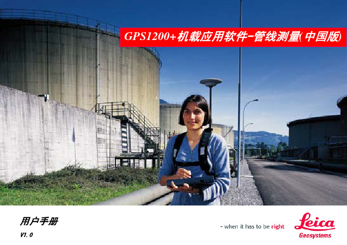
GPS1200+机载应用软件-管线测量(中国版) 说明书v1.0

用户手册 V1.0GPS1200+机载应用软件-管线测量(中国版)软件标识感谢您购买和使用GPS1200+机载管线测量应用软件。
使用中如有什么问题或修改意见,请与我们联系,我们将竭诚为您服务。
关于使用本软件的权利与义务,请参照《徕卡软件许可协议》。
软件标识在软件CD标签上,标有该软件的注册号和版本号。
请在下面填写上版本号与注册号,以便你在需要的时候,与徕卡测量系统(上海)有限公司或授权的代理商联系。
注册号:软件版本:1. 概述 (1)1.1软件的主要功能与特点 (1)1.1.1主要功能 (1)1.1.2主要特点 (1)1.2适用仪器 (1)1.3一般约定 (1)2. 软件运行操作 (3)2.1启动 (3)2.2总体结构图 (5)3. 配置模块 (6)3.1启动 (6)3.2配置/ 概要 (6)4. 特征点采集 (7)4.1启动 (7)4.2特征点采集 (7)4.3定义偏置点 (8)4.4隐藏点测量 (9)4.4.1隐藏点测量 (9)4.4.3选择方位点 (10)4.4.4斜距 (11)5. 常用计算 (12)5.1 启动 (12)5.2 常用计算 (12)5.3 管线点保存 (13)6. 数据输出 (15)6.1 启动 (15)6.2 数据输出 (15)6.3 数据格式 (15)7. 程序信息提示 (18)目录本软件按照国内管线用户的操作习惯进行开发,可通过GPS对已有管线和未还土地下管线的特征点进行快速测量或者通过已知点间接计算得到特征点坐标,以及存储管线的相关信息,并可输出测量成果。
1.1软件的主要功能与特点本软件的设计、开发依据相关的中华人民共和国国家测量规范、城市地下管线探测技术规程标准。
1.1.1主要功能①、特征点采集。
地下管线特征点的测量及存储,包括偏置点和隐藏点的计算存储。
②、常用计算。
根据已有点位和必要的观测数据利用一定的数学方法计算目标点的坐标并进行存储。
③、数据输出。
测量成果数据的输出。
GPS1200+管线测量V1.0

2
3
管线测量开始
▪ 作业:选择或新建作业;
▪ 坐标系:选择或新建一个地方
坐标系,用户也可选择通过定义 坐标系程序建立的地方坐标系;
▪ 配置集:选择或新建配置集;
▪ 天线:选择或新建天线类型;
继续
4
配置
配置/概要
在开始界面按F2配置键进入,用于选择需要显示的管线类别, 为使界面简洁,未选择的则不在测量界面显示。
▪按键操作:
返回
计算
F1返回:返回到管线测量程序菜单;
F3计算:计算目标点位并进入管线点保存对话框。
10
点位保存
启动:在特征点采集的偏置点、隐藏点测量界面按F1计算键; 或在常用计算界面按F3计算键都进入该点位保存界面。
▪按键操作: ▪F1保存:保存当前计算点位,返回 到进入该对话框之前的界面; ▪F2附属:将管线点切换为附属设施 ,显示为管线; ▪F2管线:将附属设施切换为管线点 ,显示为附属;
形时参考; ▪ 6、利用仪器的DXF输出功能可根据管线信息自动连线; ▪ 7、软件操作简单,界面友好。
16
软件的不足与注意事项
▪ 1、软件不支持对线上点进行编辑和调整顺序,因此测量过程中须 沿着线路方向进行,才能保证线的长度等信息的计算正确;
▪ 2、软件仅支持一个点只属于一条线的情况,若要测两条线交点, 请按两个点来处理;
▪ 3、若在数据管理中对已测的线进行了编辑修改,由于程序中先前 保存的数据库未修改,那么文本输出的成果与DXF的输出可能不一 致;
▪ 4、数据输出是需要一定的时间的,点越多那么时间越多,因此建 议每个作业中不要超过1000个点;
▪ 5、程序中的隐藏点测量功能与仪器自带的隐藏点测量有所不同, 不支持从Disto获取测量数据,需手工输入;
- 1、下载文档前请自行甄别文档内容的完整性,平台不提供额外的编辑、内容补充、找答案等附加服务。
- 2、"仅部分预览"的文档,不可在线预览部分如存在完整性等问题,可反馈申请退款(可完整预览的文档不适用该条件!)。
- 3、如文档侵犯您的权益,请联系客服反馈,我们会尽快为您处理(人工客服工作时间:9:00-18:30)。
在中国地区“时区”均为+8:00。按F1继续,到右上图,“仪器识别号”为仪器SN号码的后四位,自动识别,不用输入。
按F1继续,
如上,静态配置集建立完成。按F1继续回到主菜单。
第二步,新建一个作业文件。
在主菜单界面选“管理”
选“作业”进入左下图
在左上图按F2新建,如右上图,输入作业名称,描述、创建者、编码表、坐标系、平均设置均可不选,“设备”必须选CF卡,不能选内存。
然后按F1,继续到下图
按照上面图示,回车,按照我们的工作习惯选择单位设置(可以按F6换页来选择单位,角度,时间,格式等项设置),设置好以后,按F1,继续到左下图
光标在“实时模式”处回车,选择:无。
按F1,继续,到左下图
在“天线”处回车如右上图,选择“AX1202三脚架”,按F1继续回到左上图所示,“缺省高度”不输,“垂直偏置”是默认值,“量测类型”为垂直,如左上图所示。
如左上图,按F6——换页到右上图,在电台选项页选择“PacificCrestPDL”电台,
按F1继续,到左下图
如左上图按F1继续,到右上图,在“通道”处修改电台通道,每一个通道对应一个频率,可直接输入通道号值,如1,按回车键确认即可。注意,如果参考站通道选1,流动站电台通道必须也选为1,
按F1继续,设置天线,同静态一样,如下图
一步不需要知道投影方法,只需要知道一到多个点的已知平面坐标(平面坐标既可以是地方坐标也可以是北京54坐标或者西安1980坐标)和WGS84坐标即可。
绿灯
接收机有内存
绿灯闪烁
内存还剩下25%的空间
红灯
内存不足
电源灯
不亮
电源灯关闭
绿灯
电源灯打开
绿灯闪烁
电量低
二、静态测量的仪器操作(按照操作流程编制操作顺序)
1,建立一个静态配置集
2,新建一个作业
3,进入测量菜单,进行静态测量
第一步,静态配置集设置
在主菜单上选择第3个图标“管理”
选择第5项“配置集”,按F1键,到左下图
没有图标
想用CF卡,但没有插入
电量
图标
描述
一块电池在A盒中
一块电池在B盒中
两块电池放在电池盒中,现在用A电池
使用外接电源
上挡键(字母大小写切换)
图标
描述
不用上挡键
用上挡键
仪器上的三个显示灯
如果灯
是
那么
跟踪灯
不亮
没有跟踪到卫星
绿灯
接收到足够卫星
绿灯闪烁
跟踪到第一颗卫星,但是坐标没有算出来
内存灯
不亮
接收机没有内存
当要停止工作时,只需按一下F1键——停止即可回到主菜单。
四、流动站仪器操作
1,建立配置集
2,新建作业
3,测量放样
第一步,首先设置流动站的配置集。前面步骤同上,一直到
“实时模式”选择“流动站”,“实时数据”要和参考站选为一样的类型,“参考站传感器”和“参考站天线”选项如上图,按F5——设备,到左下图
左上图,按F6到右上图,按上图所示选择,按F1继续,到左下图
然后按F1继续,到左下图
如左上图,我们可以按F3来设置显示模板内容,如右上图,此项设置的功能就是让用户可以按照自己的需求来定义测量时屏幕上所显示的内容,可以设置16行。“位置和屏幕更新”可以设置屏幕上的数据刷新率。设置好以后如左上图界面。
按F1继续,到
如上图,在测量时可以使用编码设置,一般我们较少使用此设置,尤其在静态测量时完全没有必要,我们可以把“快速编码”设为——关,“主题编码”选择——不使用编码表即可。然后按F1继续,到
五,建立坐标系统
因为GPS接收机测量的坐标为WGS84坐标,而我们需要的坐标为地方平面坐标,所以必须建立一个转换关系,即建立一个坐标系,把GPS坐标转换成我们需要的坐标。
在LEICA-GPS1230接收机里面建立坐标系有三种方法,一步法,两步法,经典三维法。一般地,在不太大的区域工作(小于200平方公里)我们可以选用一步法,在大区域工作可以选用两步法和经典三维法。
在左上图中输入点号,量测的仪器高,按F1——观测,则在3D CQ会显示数值。观测时间到后,如右图,按F1——停止,再按F1保存,这个点的数据采集完成。退回到主菜单,关机,搬迁仪器到下一点,如上继续进行测量。
三、参考站仪器操作
1,建立参考站配置集
2,新建作业
3,连接仪器,设置仪器为参考站
第一步,设置参考站的配置集。
“通道”要和参考站仪器选为一样。按F1继续,到上右图
“流动站天线”按右上图所示选择,其他不变,F1继续,以后的设置同前面所讲静态设置一样。
配置集建完后返回主菜单。
第二步,新建作业,同上
第三步,在主菜单进入测量界面
如左上图,选择建立的作业,选择建好的流动站的配置集,按F1继续,到右上图,
注意右上图黄圈处的箭头应该向右下方有规律的一闪一闪,表明电台信号连通了,上图红圈处应为十字丝,才表明仪器初始化完成,得到固定解。只有固定解才满足一定的测量要求。
NO
NO
动态
NO
NO
NO
YES
动态
NO
YES
NO
YES
动态
NO
YES
通过时间
YES
动态
NO
YES
通过距离和高程
YES
快速编码
图标
描述
快速编码激活,用一个数字位来编码
关闭用一个数字位来做的快速编码。
线/面
图标
描述
在打开的工作中的线和面
CF卡和内置内存
图标
描述
CF卡插入,可以取出
CF卡插入,不能取出
内置内存被激活
按F6进入关机设置,如左下图,“恢复”选项里面两项设置均可。这项功能主要是设置仪器意外掉电后重新加电后仪器的动作。“仅仅突然丢失”掉电恢复之后接收机自动开机。“一直”掉电恢复之后接收机自动开机并回到掉电前的操作屏幕。
按F1继续,到右上图,其中“跟踪模式”一般选“最大精度”,这样仪器会自动剔除一些较差的卫星信号,只有在很恶劣的环境下(如遮挡很严重时)选择“最大跟踪”,此时仪器会把能跟踪到的卫星信号全部接收,包括较差的卫星信号,这样在测量时会带来一些较大的残差,影响测量精度,甚至在RTK测量时不能计算出固定解。“截止角”即卫星高度角限值。设为10度则卫星高度角在10度以下的卫星信号被拒绝,不接收。
按F1保存,到下图
光标在要选用的作业处,按F1继续,这个作业被选用,以后要输入数据才能进入到这个作业里面。回到主菜单。
第三步,在主菜单点击“测量“到
在左上图“作业”处选择已经建立好的作业名称,按F6到右上图选择坐标系为WGS1984,按F1继续,到下图
在“配置集”处选择已建的静态的配置集名称,在“天线”处选择如上图,按F1继续,到左下图
按F1继续,到右上图,此项设置一般选为“否”,在某些国家,必须为地震测量准备一些信息。这些信息作为地震记录输出,与每个实时测量点一起存储地震记录。地震记录存在点的注释4。对一些有特殊需求的用户才有用。
按F1继续,到
如左上图,此项设置主要是来设置快捷键所对应的功能,在测量时可按快捷键打开一些需要的功能窗口,而不需退出测量界面。“热键”可设置F7——F12键,“SHIFT热键”可设置SHIFT键和F7——F10组合键功能,“USER键菜单”可设置USER键菜单里面的功能选项。具体设置如左上图,光标于F7位置回车,如右上图,显示的是所有可选的功能,在其中任选一个作为F7的功能,选好后继续。其他的键功能设置方法一样。也可以不设置,仪器本身带有的缺省设置可以满足基本的需求。
如果右上图所示的十字丝中间有小圆圈,说明解为浮动解,精度约为分米级。
输入点号,按F1——观测,如下图,
在3D CQ处显示精度,一般地,固定解的精度应该在厘米级或者毫米级,看“RTK定位”后面的数值表示测量了几个历元。只要是固定解,测量几秒即可。
按F1停止,再按F1保存,此点测量完成,移动仪器到下一点重复测量。
按F2键“新建”,到右上图,输入配置集名称,这样相当于建立了一个配置集文件,以后只要做静态测量就可以调用这个配置集了,“描述”,“创建者”都可以不用输。然后按F1——保存,到左下图
在“向导模式”回车可以看到有两种选项,选择“查看所有内容”,则所有的设置内容全部可以涉及到,按F1,继续到右上图,选择系统语言为中文“CHINESE”,
按照上图更改,“记录原始数据”——仅静态
“记录速率”即数据采样间隔,就是多长时间记录一个原始数据历元,改为10秒或按照用户自己测量需要来进行调整。要注意的是,在同时使用几台仪器进行静态测量时,每台仪器的记录速率值必须设置成一样。
按F1继续,到
点位观测设置里面内容使用缺省设置即可。这项设置实际上主要适用于有计划的进行一些测量,比如长期参考站测量等。
用户简易操作手册
一、RX1200界面简介
1.RX1200布局
2.状态栏
二、静态的仪器操作(仪器操作----静态)
三、参考站仪器操作(仪器操作----RTK参考站)
四、流动站仪器操作(仪器操作----RTK流动站)
五、建立和确定当地(用户)坐标系统
六、实时放样
一、RX1200简介
1.RX1200布局
2. 状态栏
在主菜单上选择第3个图标“管理”,选择第5项“配置集”,然后按F2——新建,输入名字。按F1——存储,前面几个步骤与静态配置集一样,直到
在“实时模式”处回车选择——参考站,到下面窗口
在“实时数据”处选择电台数据传输类型,即数据格式,可选格式LEICA专用格式,CMR,CMR+格式,和RTCM格式,选什么样的格式都行,要注意的是,参考站选了什么格式的数据,流动站必须与之相同。“端口”可任选其一,然后按F5——设备,到左下图
